
RANSPORTATION FUNCTIONAL DESIGN TUDY … planning/da-131103-TFDS.pdf · 4.8 Public Transit...
30
T T R R A A N N S S P P O O R R T T A A T T I I O O N N F F U U N N C C T T I I O O N N A A L L D D E E S S I I G G N N S S T T U U D D Y Y S S H H I I E E L L D D B B A A Y Y D D E E V V E E L L O O P P M M E E N N T T S S I I N N C C . . T T O O W W N N O O F F O O A A K K V V I I L L L L E E Prepared For: Shieldbay Developments Inc. c/o Matson, McConnell Ltd. 2430A Bloor Street West Toronto, Ontario M6S 1P9 Prepared By: URS Canada Inc. 4 th Floor, 30 Leek Crescent Richmond Hill, Ontario L4B 4N4 November 2013 33017369.T0300
-
Upload
nguyenhanh -
Category
Documents
-
view
219 -
download
0
Transcript of RANSPORTATION FUNCTIONAL DESIGN TUDY … planning/da-131103-TFDS.pdf · 4.8 Public Transit...
TTRRAANNSSPPOORRTTAATTIIOONN FFUUNNCCTTIIOONNAALL DDEESSIIGGNN SSTTUUDDYY SSHHIIEELLDDBBAAYY DDEEVVEELLOOPPMMEENNTTSS IINNCC..
TTOOWWNN OOFF OOAAKKVVIILLLLEE
Prepared For:
Shieldbay Developments Inc. c/o Matson, McConnell Ltd.
2430A Bloor Street West Toronto, Ontario
M6S 1P9
Prepared By:
URS Canada Inc. 4th Floor, 30 Leek Crescent
Richmond Hill, Ontario L4B 4N4
November 2013 33017369.T0300

URS Canada Inc. 4th Floor, 30 Leek Crescent Richmond Hill, ON Canada L4B 4N4 Tel: 905.882.4401 Fax: 905.882.4399 www.urs.ca
November 29, 2013 Our Ref.: 33017369.T0300 Shieldbay Developments Inc. c/o Matson McConnell Ltd. 2430A Bloor Street West Toronto, Ontario M6S 1P9 Attention: Mr. Chris Matson Dear Mr. Matson: Re: Transportation Functional Design Study – Draft Plan of Subdivision
Shieldbay Developments Inc. Northeast Quadrant of Dundas Street and Postridge Drive, Town of Oakville
URS Canada Inc. is pleased to submit our report for the above noted Transportation Functional Design Study (TFDS) in support of Draft Plan of Subdivision approval. This report documents the design requirements for the internal road network and transportation elements for the proposed Shieldbay development situated on the parcel of land on the northeast quadrant of the Dundas Street and Postridge Drive intersection in the Town of Oakville. It is noted that this is a scoped TFDS reflecting the early planning stages of the development of the draft plan. Further, this document is being prepared in advance of draft plan approval and in advance of detailed engineering design. Should you have any questions regarding the study, please feel free to contact either of the undersigned at 905-882-4401. Yours very truly, URS CANADA INC.
Kevin Phillips, P. Eng., AVS Head, Municipal Transportation
Tia Nguyen, P.Eng. Transportation Engineer

TTRRAANNSSPPOORRTTAATTIIOONN FFUUNNCCTTIIOONNAALL DDEESSIIGGNN SSTTUUDDYY SSHHIIEELLDDBBAAYY DDEEVVEELLOOPPMMEENNTTSS
TTOOWWNN OOFF OOAAKKVVIILLLLEE
Prepared For:
Shieldbay Developments Inc. c/o Matson, McConnell Ltd.
2430A Bloor Street West Toronto, Ontario
M6S 1P9
Prepared By:
URS Canada Inc. 4th Floor, 30 Leek Crescent
Richmond Hill, Ontario L4B 4N4
November 2013 33017369.T0300

TTRRAANNSSPPOORRTTAATTIIOONN FFUUNNCCTTIIOONNAALL DDEESSIIGGNN SSTTUUDDYY SSHHIIEELLDDBBAAYY DDEEVVEELLOOPPMMEENNTTSS IINNCC..
TTOOWWNN OOFF OOAAKKVVIILLLLEE
Ref #: 33017369.T0300 November 2013
i
TABLE OF CONTENTS 1.0 Introduction ....................................................................................................................................... 3
1.1 Study Background ............................................................................................................................. 3
1.2 Study Need .................................................................................................................................... 5
1.3 Study Purpose ............................................................................................................................... 6
2.0 Development Plan ............................................................................................................................. 7
2.1 Location and Study Area ............................................................................................................... 7
2.2 Study Approach ............................................................................................................................ 7
2.3 Development Context ................................................................................................................... 7
3.0 Road Network .................................................................................................................................... 8
3.1 Road Network Configuration ........................................................................................................ 8
3.2 Road Classification ..................................................................................................................... 10
3.3 Signalized Traffic Control .......................................................................................................... 11
3.4 Stop Control ................................................................................................................................ 12
3.5 Exclusive Turn Lanes .................................................................................................................. 12
4.0 Design Elements .............................................................................................................................. 14
4.1 Curb Radii ................................................................................................................................... 14
4.2 Sight Daylight Triangles ............................................................................................................. 14
4.3 Intersection Spacing .................................................................................................................... 14
4.4 Intersection Design Considerations ............................................................................................ 15
4.5 Horizontal Curves ....................................................................................................................... 15
4.6 Street Elbows .............................................................................................................................. 17
4.7 Sight Distances ............................................................................................................................ 17
4.8 Public Transit Facilities .............................................................................................................. 18
4.9 Pedestrian Facilities .................................................................................................................... 21
4.10 Bikeway Facilities ....................................................................................................................... 23
4.11 On-Street Parking ........................................................................................................................ 25
4.12 Traffic Calming ........................................................................................................................... 27
4.13 Transportation Functional Plan (Pavement Marking and Traffic Signage) ................................ 27
TTRRAANNSSPPOORRTTAATTIIOONN FFUUNNCCTTIIOONNAALL DDEESSIIGGNN SSTTUUDDYY SSHHIIEELLDDBBAAYY DDEEVVEELLOOPPMMEENNTTSS IINNCC..
TTOOWWNN OOFF OOAAKKVVIILLLLEE
Ref #: 33017369.T0300 November 2013
ii
LIST OF TABLES Table 2-1: Shieldbay Development Site Statistics ........................................................................................ 7
Table 3-1: Roadway Classification and Characteristics .............................................................................. 11
Table 4-1: Curb Radii Requirements .......................................................................................................... 14
Table 4-2: Sight and Daylighting Guidelines ............................................................................................. 14
Table 4-3: Design Criteria .......................................................................................................................... 16
Table 4-4: Turning Sight Distance Review ................................................................................................. 18
LIST OF FIGURES Figure 1-1: Development Concept Plan and Site Location ........................................................................... 3
Figure 1-2: Development Draft Plan of Subdivision .................................................................................... 4
Figure 3-1: Transportation Plan for the North Oakville East Community .................................................... 9
Figure 4-1: Transit Stop Locations ............................................................................................................. 20
Figure 4-2: Draft North Oakville East Trails Plan ...................................................................................... 21
Figure 4-3: Pedestrian Sidewalk Network .................................................................................................. 22
Figure 4-4: Conceptual North Oakville East Trails and Bicycle Network ................................................. 24
Figure 4-5: Permitted On-Street Parking Plan ............................................................................................ 26

TTRRAANNSSPPOORRTTAATTIIOONN FFUUNNCCTTIIOONNAALL DDEESSIIGGNN SSTTUUDDYY SSHHIIEELLDDBBAAYY DDEEVVEELLOOPPMMEENNTTSS IINNCC..
TTOOWWNN OOFF OOAAKKVVIILLLLEE
Ref #: 33017369.T0300 November 2013
3
11..00 IINNTTRROODDUUCCTTIIOONN 1.1 Study Background The proposed Shieldbay development is located in the Town of Oakville. The proposed development is one of the blocks to be developed in the surrounding area (within the North Oakville East Secondary Plan area of the Town of Oakville) bounded by Highway 407 to the north, Dundas Street to the south, Sixteen Mile Creek to the west and Ninth Line to the east. The ultimate North Oakville community is targeted to have a future population of 55,000 and employment of 35,000. The proposed Shieldbay development is located on the northeast quadrant of Dundas Street East and Postridge Drive. The lands are proposed primarily for residential uses with a mix of urban core and institutional land uses. The locations of these lands are illustrated in Figure 1-1. Shieldbay is proposing to develop a total of 520 low and medium density residential dwelling units on the subject lands (343 single family homes, 84 semi-detached homes, and 93 townhomes). Lands at the southern limits are designated part of the Dundas Street Urban Core Area for mixed uses (potential for a mix of residential and commercial uses, and/or office uses) with a total area of 2.343 ha. Also, there is a significant amount of lands located within the Town’s Natural Heritage System (NHS) at the north limits. A school is proposed with a total area of 1.854 ha. to accommodate future residents. The Draft Plan of Subdivision is illustrated in Figure 1-2.
Figure 1-1: Development Concept Plan and Site Location

TTRRAANNSSPPOORRTTAATTIIOONN FFUUNNCCTTIIOONNAALL DDEESSIIGGNN SSTTUUDDYY SSHHIIEELLDDBBAAYY DDEEVVEELLOOPPMMEENNTTSS IINNCC..
TTOOWWNN OOFF OOAAKKVVIILLLLEE
Ref #: 33017369.T0300 November 2013
4
Figure 1-2: Development Draft Plan of Subdivision1
Note: Not to scale
1 Source: Matson, McConnell Ltd., September 18, 201

TTRRAANNSSPPOORRTTAATTIIOONN FFUUNNCCTTIIOONNAALL DDEESSIIGGNN SSTTUUDDYY SSHHIIEELLDDBBAAYY DDEEVVEELLOOPPMMEENNTT
TTOOWWNN OOFF OOAAKKVVIILLLLEE
Ref #: 33017369.T0300 November 2013
5
1.2 Study Need The Shieldbay development lands are being developed for a mix of residential, urban core, and institutional uses. A Transportation Functional Design Study report (TFDS) has been prepared in support of the Shieldbay development application. The Town of Oakville’s North Oakville -Terms of Reference for Transportation Impact Studies and Transportation Functional Design Studies have been reviewed. URS has referenced the Terms of Reference to ensure satisfaction of the stipulated TFDS submission requirements. Many of the elements of the TFDS are documented in the Transportation Impact Study (TIS) report, prepared for Shieldbay Development Inc. by URS dated October 2013. It is a stand-alone report entitled Transportation Impact Study, Shieldbay Development Inc. Since the TIS report did not address the internal detailed requirements of a TFDS, this study has been prepared by URS to document the internal plan and design requirements on a local scale. The following reports were the background materials reviewed during the preparation of this study:
• Transportation Impact Study for Shieldbay Developments Inc., Town of Oakville, prepared by URS Canada Inc., October 2013;
• Transit Facilities Plan for Shieldbay Developments Inc., Town of Oakville, prepared by URS Canada Inc., October 2013;
• North Oakville – Terms of Reference for Transportation Impact Studies and Transportation Functional Design Studies, Town of Oakville, August 2009;
• North Oakville Secondary Plan – Transit Plan, Town of Oakville, August 2009; • Oakville North Park Traffic Impact Analysis, Town of Oakville, February 2009; • North Oakville East Secondary Plan (Official Plan Amendment), Town of Oakville, February
2008; • North Oakville East Urban Design and Open Space Guidelines, Town of Oakville, April 2008
(Draft); • North Oakville East Trails Plan, Town of Oakville, May 20, 2008; • Oakville Transportation Master Plan, Town of Oakville, March 30, 2007; • Region of Halton Roads Capital Projects Plan [2013 – 2031], Regional Municipality of Halton,
December 2012; • Dundas Street (Regional Road 5) Bus Rapid Transit (BRT) Corridor Studies (from Brant Street
(Regional Road 18) to Trafalgar Road (Regional Road 3)); • Trafalgar Road (Regional Road 3) Bus Rapid Transit (BRT) Corridor Studies (from Cornwall
Road to 407 ETR); • Geometric Design Standards for Ontario Highways, Ministry of Transportation of Ontario; • Geometric Design Guide for Canadian Roads, Transportation Association of Canada (TAC),
1999; • Canadian Transit Handbook, Second Edition, Canadian Urban Transit Association, 1985;
TTRRAANNSSPPOORRTTAATTIIOONN FFUUNNCCTTIIOONNAALL DDEESSIIGGNN SSTTUUDDYY SSHHIIEELLDDBBAAYY DDEEVVEELLOOPPMMEENNTT
TTOOWWNN OOFF OOAAKKVVIILLLLEE
Ref #: 33017369.T0300 November 2013
6
• Ontario Traffic Manual, Book 5, Regulatory Signs, Ministry of Transportation of Ontario, March 2000; and
• Ontario Traffic Manual, Book 12, Traffic Signals, Ministry of Transportation of Ontario, November 2007.
The plan and design of the Draft Plan of Subdivision is generally consistent with the principles and recommendations within the Transportation Impact Study for Shieldbay Developments Inc. report. Any refinements are noted in this study.
1.3 Study Purpose URS Canada Inc. was retained by Sheildbay Developments Inc. to provide transportation planning and traffic engineering services with respect to the preparation of the Transportation Functional Design Study for the proposed Shieldbay development. It is noted that the TFDS has been prepared in support of a Draft Plan of Subdivision approval. The purpose of the study was to determine:
• The effect that the development will have on both the North Oakville transportation system and site traffic;
• The appropriate improvements to accommodate the development; and
• Road functions, geometrics and design for all modes of travel. A Transportation Functional Design Study report has been prepared to document the study methodology, findings, and recommendations associated with the Shieldbay development. It is noted that this TFDS reflecting the early planning stages of the development of the draft plan. Further, no engineering plans have been provided at this time as this document is being prepared in advance of draft plan approval.

TTRRAANNSSPPOORRTTAATTIIOONN FFUUNNCCTTIIOONNAALL DDEESSIIGGNN SSTTUUDDYY SSHHIIEELLDDBBAAYY DDEEVVEELLOOPPMMEENNTT
TTOOWWNN OOFF OOAAKKVVIILLLLEE
Ref #: 33017369.T0300 November 2013
7
22..00 DDEEVVEELLOOPPMMEENNTT PPLLAANN
2.1 Location and Study Area The proposed development is one of the blocks to be developed in the surrounding area (named the North Oakville East Secondary Plan by the Town of Oakville) bounded by Highway 407 to the north, Dundas Street to the south, Sixteen Mile Creek to the west and Ninth Line to the east. The ultimate North Oakville community is targeted to have a future population of 55,000 and employment of 35,000. The Town’s planning approach in North Oakville is to develop a Transit-First community, the planning related attributes within the North Oakville lands that promote non-auto travel include consolidated mixed-use development in compact urban form, transit supportive land use densities, a pedestrian/cyclist friendly grid base street system, as well as effective parking management strategies within the community. The subject lands are located within the Town of Oakville and are generally bounded by Natural Heritage System lands to the north, Dundas Street to the south, Eighth Line to the east, and Postridge Drive to the west.
2.2 Study Approach
A 2018 horizon period was selected to assess future traffic conditions and transportation needs associated with the proposed development since it corresponds to the horizon year employed in the Transportation Impact Study for Shieldbay Developments Inc., Town of Oakville prepared by URS. In addition, proposed developments on adjacent lands and other future traffic changes are also accounted for in this assessment. The traffic data for the subject lands is generally based on the Transportation Impact Study for Shieldbay Developments Inc. The basis for this study were the Terms of Reference for Transportation Impact Studies and Transportation Functional Design Studies, prepared by staff at the Town of Oakville, as well as consultation with Town staff.
2.3 Development Context Shieldbay development is proposing to develop a total of 520 low and medium density residential dwelling units on the subject lands (343 single family homes, 84 semi-detached homes, and 93 townhomes). Lands at the southern limits are designated part of the Dundas Street Urban Core Area for mixed uses (potential for a mix of residential and commercial uses, and/or office uses) with a total area of 2.343 ha. Also, there is a significant amount of lands located within the Town’s Natural Heritage System (NHS) at the northern limits. A school is proposed with a total area of 1.854 ha. to accommodate future residents. Table 2-1 summarizes the Shieldbay development site statistics.
Table 2-1: Shieldbay Development Site Statistics
Land Use Units / GFA
Residential
343 84 93
520
Detached Semi Detached Townhouse Total
Urban Core 2.434 182
Ha. Units
Institutional 1.854 Ha.
TTRRAANNSSPPOORRTTAATTIIOONN FFUUNNCCTTIIOONNAALL DDEESSIIGGNN SSTTUUDDYY SSHHIIEELLDDBBAAYY DDEEVVEELLOOPPMMEENNTT
TTOOWWNN OOFF OOAAKKVVIILLLLEE
Ref #: 33017369.T0300 November 2013
8
33..00 RROOAADD NNEETTWWOORRKK
3.1 Road Network Configuration
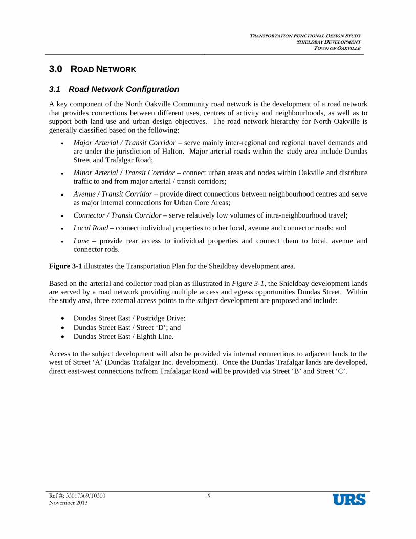
A key component of the North Oakville Community road network is the development of a road network that provides connections between different uses, centres of activity and neighbourhoods, as well as to support both land use and urban design objectives. The road network hierarchy for North Oakville is generally classified based on the following:
• Major Arterial / Transit Corridor – serve mainly inter-regional and regional travel demands and are under the jurisdiction of Halton. Major arterial roads within the study area include Dundas Street and Trafalgar Road;
• Minor Arterial / Transit Corridor – connect urban areas and nodes within Oakville and distribute traffic to and from major arterial / transit corridors;
• Avenue / Transit Corridor – provide direct connections between neighbourhood centres and serve as major internal connections for Urban Core Areas;
• Connector / Transit Corridor – serve relatively low volumes of intra-neighbourhood travel;
• Local Road – connect individual properties to other local, avenue and connector roads; and
• Lane – provide rear access to individual properties and connect them to local, avenue and connector rods.
Figure 3-1 illustrates the Transportation Plan for the Sheildbay development area. Based on the arterial and collector road plan as illustrated in Figure 3-1, the Shieldbay development lands are served by a road network providing multiple access and egress opportunities Dundas Street. Within the study area, three external access points to the subject development are proposed and include:
• Dundas Street East / Postridge Drive; • Dundas Street East / Street ‘D’; and • Dundas Street East / Eighth Line.
Access to the subject development will also be provided via internal connections to adjacent lands to the west of Street ‘A’ (Dundas Trafalgar Inc. development). Once the Dundas Trafalgar lands are developed, direct east-west connections to/from Trafalagar Road will be provided via Street ‘B’ and Street ‘C’.

TTRRAANNSSPPOORRTTAATTIIOONN FFUUNNCCTTIIOONNAALL DDEESSIIGGNN SSTTUUDDYY SSHHIIEELLDDBBAAYY DDEEVVEELLOOPPMMEENNTT
TTOOWWNN OOFF OOAAKKVVIILLLLEE
Ref #: 33015991.T0100 November 2013
9
Figure 3-1: Transportation Plan for the North Oakville East Community

TTRRAANNSSPPOORRTTAATTIIOONN FFUUNNCCTTIIOONNAALL DDEESSIIGGNN SSTTUUDDYY SSHHIIEELLDDBBAAYY DDEEVVEELLOOPPMMEENNTTSS IINNCC..
TTOOWWNN OOFF OOAAKKVVIILLLLEE
Ref #: 33017369.T0300 November 2013
10
3.2 Road Classification Table 3-1 summarizes the proposed classification for the internal roads of the Shieldbay development plan. The following characteristics are noted for each road:
• Classifications; • Street name; • Right-of-way width; • Pavement widths, including number of lanes and proposed lane widths; • Boulevard width; • Parking provisions; and • Sidewalk provisions.
The overall classification for each road was based on a review of each corridor’s service function (i.e. mobility and/or access), traffic volumes, flow characteristics (i.e. interrupted or uninterrupted), anticipated speeds, vehicle types, road and entrance connectivity, transit servicing, cyclists and pedestrian facilities, and parking provisions. Typical design elements in the road network for the Shieldbay development plan are based on the Town’s design guidelines for the North Oakville community, which are outlined as follows:
• Speed limits: Avenue and connector roads are generally to be posted at 50 km/h. Local roads are to be posted at 40 km/h;
• Lane widths: Lane widths at 4.00 metres for avenue roads, 3.50-3.75 metres for connector roads, and 3.00-3.25 metres for local roads;
• On-street parking: Parking will be permitted according to road classification as summarized in Table 3-1. Additional information regarding on-street parking is outlined in Section 4.11 - On-street Parking;
• Mid-block Right-of-way: The road rights-of-way within the study area range from 17.0 metres for a local road to 22.0 metres for an avenue road. The right-of-way of the laneways are 7.5 metres; and
• Sidewalks: All streets are to include a 1.5-metre wide sidewalk along both sides of the road, except for laneways, as summarized in Table 3-1.

TTRRAANNSSPPOORRTTAATTIIOONN FFUUNNCCTTIIOONNAALL DDEESSIIGGNN SSTTUUDDYY SSHHIIEELLDDBBAAYY DDEEVVEELLOOPPMMEENNTTSS IINNCC..
TTOOWWNN OOFF OOAAKKVVIILLLLEE
Ref #: 33017369.T0300 November 2013
11
Table 3-1: Roadway Classification and Characteristics
Road Classification Road(s)
Mid-block
Right-of-Way
(metres)
Pavement Width
(metres)
Lanes and Widths (metres)
Boulevard (metres)
On-Street
Parking Sidewalks
Avenue/ Transit Corridor
- Street ‘A’
24.0 m
12.5 m
2 Lane @ 4.00 m 2 Parking Lane @ 2.25 m
2 @ 5.75 m Both Side
1.50 m sidewalk on both
sides Avenue/ Transit Corridor
- Street ‘B’ 22.0 m 12.5 m
2 Lane @ 4.00 m 2 Parking Lane @ 2.25 m
2 @ 4.75 m Both Side
1.50 m sidewalk on both
sides Connector/ Transit Corridor
-Street ‘C’ 19.0 m 9.5 m 1 Lane @ 3.75 m 1 Lane @ 3.50 m 1 Parking Lane @ 2.25 m
2 @ 4.75 m One Side 1.50 m sidewalk on both
sides Local Street - Street ‘D’
- Street ‘E’ - Street ‘F’ - Street ‘G’ - Street ‘H’ - Street ‘I’ - Street ‘J’ - Street ‘K’ - Street ‘L’ - Street ‘M’ - Street ‘O’
17.0 m
8.5 m 1 Lane @ 3.25 m 1 Lane @ 3.00 m 1 Parking Lane @ 2.25 m
2 @ 4.25 m One Side 1.50 m sidewalk on both
sides
Laneway - Lane ‘P’ 7.5 m 4.6 m 2 @ 1.45 m N/A N/A 3.3 Signalized Traffic Control
The requirements for the installation of signalized traffic control at the key study area intersections are based on the signal warrant methodology outlined by the Ontario Ministry of Transportation in the Ontario Traffic Manual – Book 12, Traffic Signals and supplementary policy.
Based on the 2018 horizon year future total traffic volumes and the MTO methodology, signalized controls or underground provisions (such as handwells and ducting) are not warranted at any internal locations within the Shieldbay development. There are existing traffic signal controls along external locations at Dundas Street / Street ‘A’ and Dundas Street / Street C’ intersection within the study area. Further, signalized traffic controls are not warranted at the proposed Dundas Street / Street ‘D’ intersection. It is noted the infrastructure improvements along Dundas Street being undertaken by the Region of Halton will provide for a centre median island at Street ‘D’, as such eastbound and westbound traffic will be restricted to right-in and right-out movements, therefore precluding the need for traffic signal controls.
TTRRAANNSSPPOORRTTAATTIIOONN FFUUNNCCTTIIOONNAALL DDEESSIIGGNN SSTTUUDDYY SSHHIIEELLDDBBAAYY DDEEVVEELLOOPPMMEENNTTSS IINNCC..
TTOOWWNN OOFF OOAAKKVVIILLLLEE
Ref #: 33017369.T0300 November 2013
12
3.4 Stop Control
At local road “T” intersections, the bisecting road should be stop controlled. At four-legged intersections, stop signs are usually required on the approach for the road of lower classification or with lower traffic volumes. In a case where two intersecting roads are of the same classification with similar traffic demands, stop signs are usually installed on the east-west road.
The need for all-way stop-control was determined based on the criteria in the Ontario Traffic Manual – Book 5, Regulatory Signs. Two conditions must be met for the all-way stop warrant on minor roads to be satisfied, namely, that the total vehicle volume on all intersection approaches must exceed 350 for the highest hour recorded and that the volume split does not exceed 75/25 for three-way control or 65/35 for four-way control.
Based on a review of the future total traffic volumes, all-way stop control is not warranted at any of the internal intersections within the Shieldbay development.
3.5 Exclusive Turn Lanes The Transportation Impact Study for Shieldbay Development documents locations within the North Oakville Community development lands where external turn lanes are recommended.
The need for exclusive left and right turn lanes at the intersections within the Shieldbay development was reviewed. Exclusive turn lanes have been identified for the Shieldbay development at the following locations:
• Dundas Street / Postridge Drive – Street ‘A’ o There is an existing lane designated for eastbound left turn movements; however it is
currently hatched out and restricted from usage. The existing laning provides for a 90 metre parallel and 75 metre taper sections. Under future conditions, the exclusive left turn lane will be available to accommodate site traffic; and
o Provide an auxiliary southbound left turn lane and shared southbound through/right turn lane.
• Dundas Street / Street ‘D’ o Southbound movement will be restricted to right turn movements only.
The need for exclusive left turn lanes at internal intersections were investigated based on the requirements laid out in the MTO publication entitled Geometric Design Standards for Ontario Highways (GDSOH). Based on a review of the internal traffic volumes, exclusive turn lanes are not required at internal intersections within the Shieldbay development. Intersection laning requirements for the Shieldbay development are illustrated in Figure 3-2. The future lane configurations along Dundas Street and Trafalgar Road are based on the preliminary design concept of the current Trafalgar Road and Dundas Street Corridor Studies, as well as the Traffic Impact Analysis (TIA) Report for Oakville North Park (dated February 2009).

TTRRAANNSSPPOORRTTAATTIIOONN FFUUNNCCTTIIOONNAALL DDEESSIIGGNN SSTTUUDDYY SSHHIIEELLDDBBAAYY DDEEVVEELLOOPPMMEENNTTSS IINNCC..
TTOOWWNN OOFF OOAAKKVVIILLLLEE
Ref #: 33017369.T0300 November 2013
13
Figure 3-2: Transportation Plan for the Shieldbay Development
1 13 37 25 97
Proposed Shieldbay DevelopmentNortheast of Dundas Street / Trafalgar Road Intersection, Town of Oakville, Ontario
LEGEND2018 Future Lane Configuration Proposed Stop S Existing Laning Proposed Laning
Traffic Signal Existing Road Network Proposed Road Network
Date: Subject LandsT:\Projects\1-33017369-Shieldbay Oakville (MM)\07-Analysis and Volumes\01-TDM\[TMD_Shieldbay.xlsm]V_ft18
23-Oct-13 Column 33Not To Scale
Postridge Drive
Street 'D'
Trafalgar Road Eighth Line
Street 'A' Street 'C'
Dundas Street

TTRRAANNSSPPOORRTTAATTIIOONN FFUUNNCCTTIIOONNAALL DDEESSIIGGNN SSTTUUDDYY SSHHIIEELLDDBBAAYY DDEEVVEELLOOPPMMEENNTTSS IINNCC..
TTOOWWNN OOFF OOAAKKVVIILLLLEE
Ref: 33017369.T0300 November 2013
14
44..00 DDEESSIIGGNN EELLEEMMEENNTTSS Engineering designs have not been developed at this time; however, the following sections provide design guidance and commentary for design.
4.1 Curb Radii The treatments for curb radii to be employed for all intersections are generally based on the TAC guidelines and are summarized in Table 4-1.
Table 4-1: Curb Radii Requirements
Intersection Type Curb Radius (m) Laneways - Residential 3.5 m radius
Local Roads - Residential 7.5 m radius Connectors or Avenues 10.5 m radius
Minor / Major Arterial Roads 15.0 m radius
Curbs at intersections within the Shieldbay development should meet the above requirements for radii. These standards should be employed to facilitate vehicle turning maneuvers, in addition to enhancing pedestrian safety via minimized pedestrian crossing distances and also reduced vehicle speeds undertaking right turns at intersections.
4.2 Sight Daylight Triangles
The treatment standards for intersection sight daylighting triangles are identified in the Town’s Terms of Reference for Transportation Impact Studies and Transportation Functional Design Studies and summarized in Table 4-2.
Table 4-2: Sight and Daylighting Guidelines
The designs of the sight daylighting triangles at all the intersections within the Shieldbay development meet the above noted requirements.
4.3 Intersection Spacing
Town of Oakville’s intersection spacing requirements are based on TAC and Ontario Traffic Manual (OTM) guidelines which are as follows:
• Local Roadways: Minimum adjacent four-leg intersection spacing is 60 metres (between centrelines);
• Connector and Avenue Roadways: Minimum intersection spacing is 60 metres;
Road Type Local Roads Connectors / Avenues
Minor Arterial Roads
Major Arterial Roads
Local Roads 3.5 m x 3.5 m 3.5 m x 3.5 m 7.5 m x 7.5 m 15 m x 15 m Connectors / Avenues - 7.5 m x 7.5 m 10.5 m x 10.5 m 15 m x 15 m
Minor Arterial Roads - - 15 m x 15 m 15 m x 15 m
Major Arterial Roads - - - 15 m x 15 m

TTRRAANNSSPPOORRTTAATTIIOONN FFUUNNCCTTIIOONNAALL DDEESSIIGGNN SSTTUUDDYY SSHHIIEELLDDBBAAYY DDEEVVEELLOOPPMMEENNTTSS IINNCC..
TTOOWWNN OOFF OOAAKKVVIILLLLEE
Ref: 33017369.T0300 November 2013
15
• Minor Arterial: Minimum spacing between signalized intersections is 200 metres;
• Major Arterial: Minimum spacing between signalized intersections is 400 metres; and
• Adjacent All-Way Stop Condition: Minimum intersection spacing is 250 metres.
External Intersection Spacing:
Based on the above noted criteria, intersection spacing for all the external intersections within the study area meet the requirements for the intersection spacing along Dundas Street between Trafalgar Road and Eighth Line.
Internal Intersection Spacing:
Based on the above noted criteria, it was noted that the intersection spacing for all the internal intersections within the study area meet the requirements for the intersection spacing.
4.4 Intersection Design Considerations
The following are additional internal intersection design criteria based on the updated Geometric Design Guide for Canadian Roads, prepared by TAC in 1999:
• Intersection angle of at least 70 degrees to no more than 110 degrees, although 80 degrees to 100 degrees is preferable. In many cases for green-field development, it is often desirable for major intersections to intersect at no greater than ±3 degrees from 90 degrees; and
• Opposite intersections, approaches are to be aligned on a mutual tangent line. Minor street approaches should be tangential for a distance of 60 metres from a Regional road.
In addition to the above noted criteria, it is recommended that the intersections with Regional roads (i.e. Dundas Street) intersect at no greater than ±3 degrees from 90 degrees. The internal intersection alignments for roads within the Shieldbay development are based on the aforementioned criteria, except for the following intersections:
• Dundas Street / Street ‘D’- has an intersection angle of 97 degree. Although the intersection is skewed at an angle of approximately 7 degrees, the opposite intersection approaches are aligned on a mutual tangent line and the skew is within the minimum design practice of 70 – 110 degrees. Street ‘D’ is expected to have low operating speeds and low traffic volumes. In addition, southbound traffic is to be under stop-controlled at Dundas Street and restricted to only southbound right turns. As such, the intersection skew condition is deemed to be acceptable;
4.5 Horizontal Curves
Geometric design of roads is to be based on the TAC’s Urban Supplement to the Geometric Design Guide for Canadian Roads and Geometric Design Guide for Canadian Roads. Additionally, the Ministry of Transportation of Ontario’s Geometric Design Standards for Ontario Highways are also referenced for defining horizontal alignment and vertical profile.
Table 4-3 summarizes the appropriate design parameters for the internal roads.

TTRRAANNSSPPOORRTTAATTIIOONN FFUUNNCCTTIIOONNAALL DDEESSIIGGNN SSTTUUDDYY SSHHIIEELLDDBBAAYY DDEEVVEELLOOPPMMEENNTTSS IINNCC..
TTOOWWNN OOFF OOAAKKVVIILLLLEE
Ref: 33017369.T0300 November 2013
16
Table 4-3: Design Criteria
PARAMETER ROAD CLASSIFICATION
Local Street Connector /Transit Corridor
Avenue / Transit Corridor
Design Speed 40 km/h 60 km/h 60 km/h Posted Speed (recommended) 40 km/h 50 km/h 50 km/h Minimum Pavement Width
(face to face of curbs) 8.5 m 9.5 m 12.5 m
Minimum Centreline Curve Radius* 84 m 189 m 189 m Note: It was assumed that there is no super-elevation and the coefficient of side fiction force (f) is 0.15.
Horizontal curves for the Shieldbay development are based on the above criteria, however, there are some exceptions, and these include:
• Street ‘D’: Comprises a 50-metre radius curve over a length of approximately 40 metres in the vicinity of Lot 202 south of Street ‘C’, which is less than the requirement for a local street. Street ‘D’ is to be posted at 40 km/h and stop controlled at the approaches to Street ‘C’, as such, vehicular operating speeds are generally not anticipated to be excessive. Further, given the short span of the curved road section, visibility would not be impeded. Thus, this radius is deemed to be acceptable. Parking is to be prohibited on the inside of the curve;
• Street ‘L’: Comprises a 50 metre radius curve over a length of approximately 40 metres in the vicinity of Lot 233 south of Street ‘C’, which is less than the requirement for a local street. Street ‘L’ is to be posted at 40 km/h and stop controlled at the approaches to Street ‘C’, as such, vehicular operating speeds are generally not anticipated to be excessive. Further, given the short span of the curved road section under stop control at the northern and southern limits, visibility would not be impeded. Thus, this radius is deemed to be acceptable. Parking is to be prohibited on the inside of the curve;
• Street ‘K’: Comprises a 15 metre radius curve over a length of approximately 15 metres in the vicinity of Lot 254 south of Street ‘C’, which is less than the requirement for a local street. Street ‘K’ is to be posted at 40 km/h and stop controlled at the approaches to Street ‘C’, as such, vehicular operating speeds are generally not anticipated to be excessive. Further, given the short span of the curved road section under stop control at the northern and southern limits, visibility would not be impeded. Thus, this radius is deemed to be acceptable. Parking is to be prohibited on the inside of the curve;
• Street ‘M’ (east): Comprises a 50 metre radius curve over a length of approximately 60 metres in the vicinity of Lot 2 north of Street ‘C’, which is less than the requirement for a local street. Street ‘M’ is to be posted at 40 km/h and stop controlled at the approaches to Street ‘C’, as such, vehicular operating speeds are generally not anticipated to be excessive. Further, given the short span of the curved road section, visibility would not be impeded. Thus, this radius is deemed to be acceptable. Parking is to be prohibited on the inside of the curve;
• Street ‘N’: Comprises a 50 metre radius curve over a length of approximately 60 metres in the vicinity of Lot 47 north of Street ‘C’, which is less than the requirement for a local street. Street ‘N’ is to be posted at 40 km/h and stop controlled at the approaches to Street ‘C’, as such, vehicular operating speeds are generally not anticipated to be excessive. Further, given the short span of the curved road section, visibility would not be impeded. Thus, this radius is deemed to be acceptable. Parking is to be prohibited on the inside of the curve;
• Street ‘M’ (west): Comprises a 30-metre radius curve over a length of approximately 40 metres in the vicinity of Lot 105 north of Street ‘C’, which is less than the requirement for a local street.

TTRRAANNSSPPOORRTTAATTIIOONN FFUUNNCCTTIIOONNAALL DDEESSIIGGNN SSTTUUDDYY SSHHIIEELLDDBBAAYY DDEEVVEELLOOPPMMEENNTTSS IINNCC..
TTOOWWNN OOFF OOAAKKVVIILLLLEE
Ref: 33017369.T0300 November 2013
17
Street ‘M’ is to be posted at 40 km/h and stop controlled at the approaches to Street ‘C’, as such, vehicular operating speeds are generally not anticipated to be excessive. Further, given the short span of the curved road section, visibility would not be impeded. Thus, this radius is deemed to be acceptable. Parking is to be prohibited on the inside of the curve;
• Street ‘O’: Comprises a 17-metre radius curve over a length of approximately 15 metres in the vicinity of Lot 89 south of Street ‘M’, which is less than the requirement for a local street. Street ‘O’ is to be posted at 40 km/h and stop controlled at the approaches to Street ‘C’, as such, vehicular operating speeds are generally not anticipated to be excessive. Further, given the short span of the curved road section, visibility would not be impeded. Thus, this radius is deemed to be acceptable. Parking is to be prohibited on the inside of the curve;
4.6 Street Elbows
Street elbows are often constructed on local roads with a general right-angle curvature of about 80 to 100 degrees. At the following locations, the pavement width of the road is often “bulbed” through the curve to facilitate large vehicle turning, to provide wider residential unit frontage (where applicable), and to improve residential unit entrance locations.
There are several angular deflection identified within the Shieldbay development. Locations are listed as follows:
• Street ‘M’ of Lot “24”;
• Street ‘M’ of Lot “92”;
However, in lieu of creating wider streets by incorporating street elbows, on-street parking should be prohibited at these locations to enhance visibility and mobility for large vehicles through the length of the curves, as discussed in Section 4.11 – On-street Parking.
4.7 Sight Distances
The geometric elements (daylighting, curb radii, horizontal/vertical alignments, etc.) within the Shieldbay lands will be designed according to the Town of Oakville’s geometric standards. A sightline review was conducted for notable locations within the Shieldbay development which include the Street ‘C’ / Street ‘D’ - Street ‘N’ intersection (the concerns are related to the available sightlines for the turning vehicles on the minor approach to Street ‘C’ given the potential locations of some of the sideyard fences). Table 4-4 summarizes the available sight distances versus the design standards based on the TAC guidelines:

TTRRAANNSSPPOORRTTAATTIIOONN FFUUNNCCTTIIOONNAALL DDEESSIIGGNN SSTTUUDDYY SSHHIIEELLDDBBAAYY DDEEVVEELLOOPPMMEENNTTSS IINNCC..
TTOOWWNN OOFF OOAAKKVVIILLLLEE
Ref: 33017369.T0300 November 2013
18
Table 4-4: Turning Sight Distance Review Available Sight
Distance Design Standards
(Based on TAC – Design Speed)
Street ‘C’ and Street ‘N’ (North) Intersection
Right Turning Sight Distance From Street ‘N’ (Looking East) >160m
160 m (SD = 60 km/h) 120 m (SD = 50 km/h) 90 m (SD = 40 km/h)
Left Turning Sight Distance From Street ‘N’ (Looking West) ~95m
160 m (SD = 60 km/h) 120 m (SD = 50 km/h) 90 m (SD = 40 km/h)
Street ‘C’ and Street ‘D’ (South) Intersection
Right Turning Sight Distance From Street ‘D’ (Looking West) ~75m
160 m (SD = 60 km/h) 120 m (SD = 50 km/h) 90 m (SD = 40 km/h)
Left Turning Sight Distance From Street ‘D’ (Looking East) >160m
160 m (SD = 60 km/h) 120 m (SD = 50 km/h) 90 m (SD = 40 km/h)
For the Street ‘C’ and Street ‘N’ intersection, the available sight distance looking east exceeds the requirement for a design speed of 60 km/h. However, the available sight distance looking west is less than the required 120 m for a design speed of 60 km/h (but greater than a 40 km/h design speed) due the horizontal curve. For the Street ‘C’ and Street ‘D’ intersection, the available sight distance looking west is less than the requirement for a design speed of 60 km/h due to the horizontal curve. However, the available sight distance looking east exceeds the requirement for a design speed of 60 km/h. Given that there is a school located immediately to the west of Street ‘C’ / Street ‘N’ – Street ‘D’ intersection; it is recommended that the posted speed within the vicinity of the school site should be reduced from posted speed of 50 km/h to 40 km/h. Further, an on-street parking lane is proposed on Street ‘C’; as such, on-street parking is to be prohibited within the vicinity of the horizontal curve. This would provide for enhanced visibility through the horizontal curve between Street ‘O’ and Street ‘N’ – Street ‘D’.
4.8 Public Transit Facilities According to the Town of Oakville’s Transit Plan (August 2009) and the North Oakville Secondary Plan Transit Plan Developer’s Toolkit, local transit routes provide coverage such that most residences, and all schools, neighbourhood centres and public facilities are within a walking distance of no more than 400 metres of a bus stop. Bus stops should be placed at most intersections along the routes, passenger generators, and transfer points. Bus stop spacing should be approximately 250-300 metres (not less than 200 metres). It is also noted that transit stop spacing along transit routes is typically 250 metres.
The transit routing is complimented with a comprehensive network of sidewalks and bicycle connections throughout the community to facilitate walking and cycling to transit stops. This includes sidewalks on both sides of all streets and multi-use path or trail connections to link the adjacent sidewalks. Based on the Draft North Oakville East Trails Plan, the conceptual bicycle network within the study area (as illustrated in Figure 4-1) includes:
• Trafalgar Road – It is a designated Regional Bicycle Facility;

TTRRAANNSSPPOORRTTAATTIIOONN FFUUNNCCTTIIOONNAALL DDEESSIIGGNN SSTTUUDDYY SSHHIIEELLDDBBAAYY DDEEVVEELLOOPPMMEENNTTSS IINNCC..
TTOOWWNN OOFF OOAAKKVVIILLLLEE
Ref: 33017369.T0300 November 2013
19
• Dundas Street – It is a designated Regional Bicycle Facility;
• The east/west and north/south Major Trail (off road) within the Natural Heritage Area;
• Street ‘B’ – It is a designated Signed Bike Route (on-road) between Postridge Drive and Eighth Line; and
• Street ‘C’ – It is a designated Signed Bike Route (on-road) between Postridge Drive and Eighth Line;
Based on the criteria as stated in the Town of Oakville’s Transit Plan (August 2009) and the North Oakville Secondary Plan Transit Plan Developer’s Toolkit, as well as a review of the Draft Plan of Subdivisions, transit stops are strategically proposed within the study area. The following is a summary of the proposed transit stop locations within the Shieldbay development:
• Stop A - Will be a sheltered ‘Info’ stop, with a bench, shelter, lighting, power pedestal and wheelchair landing pad;
• Stop B - Will be an ‘Info’ stop with a bench, lighting, power pedestal and wheelchair landing pad;
• Stop C - Will be a ‘Comfort’ stop with a bench and wheelchair landing pad; and
• Stop D - Will be a ‘Basic’ stop implemented at the maximum spacing of 250 metres along a transit route.
Figure 4-1 illustrates the proposed transit stop locations and types within the Shieldaby development. It should be noted that these are preliminary locations for consideration, the stop locations and types should be reviewed when the ultimate transit routing plan is available given that some of the stops may not be required due to the potential for consolidated stops.

TTRRAANNSSPPOORRTTAATTIIOONN FFUUNNCCTTIIOONNAALL DDEESSIIGGNN SSTTUUDDYY SSHHIIEELLDDBBAAYY DDEEVVEELLOOPPMMEENNTTSS IINNCC..
TTOOWWNN OOFF OOAAKKVVIILLLLEE
Ref: 33017369.T0300 November 2013
20
Figure 4-1: Transit Stop Locations

TTRRAANNSSPPOORRTTAATTIIOONN FFUUNNCCTTIIOONNAALL DDEESSIIGGNN SSTTUUDDYY SSHHIIEELLDDBBAAYY DDEEVVEELLOOPPMMEENNTTSS IINNCC..
TTOOWWNN OOFF OOAAKKVVIILLLLEE
Ref: 33017369.T0300 November 2013
21
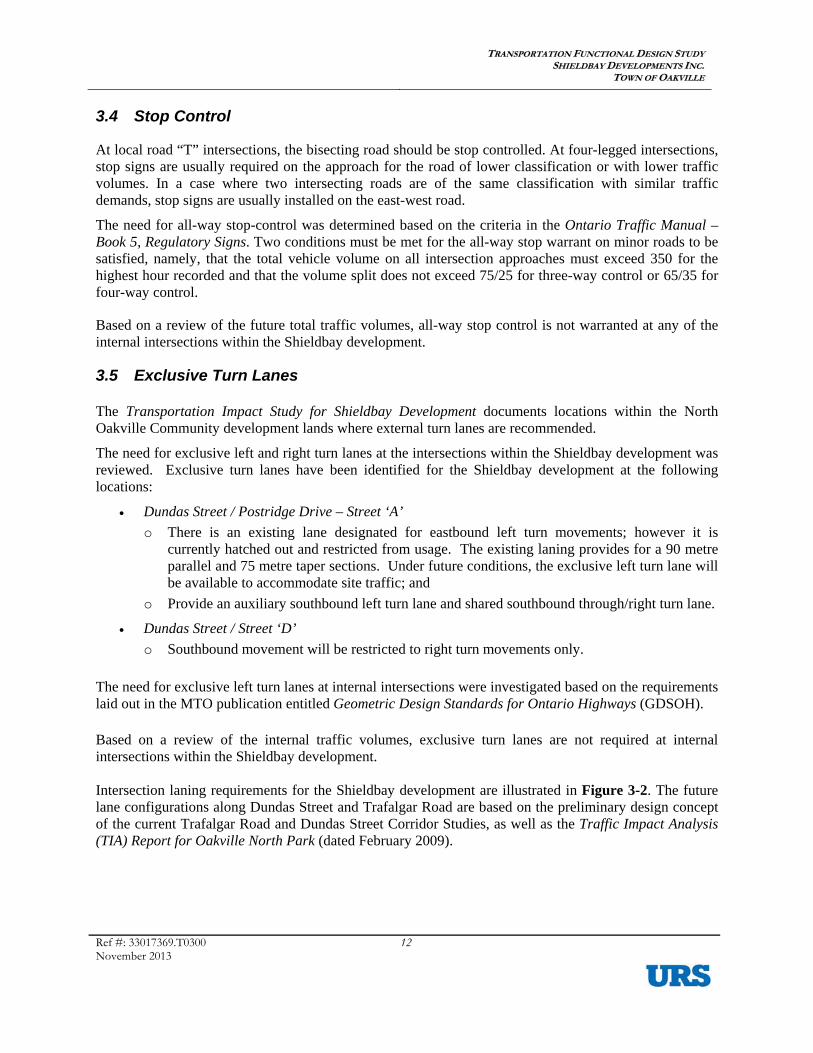
4.9 Pedestrian Facilities A comprehensive network of sidewalks and sidewalk connections is proposed to provide for convenient movement throughout the North Oakville Secondary Plan area. Sidewalk connections should also be incorporated to link sidewalks to paths and other walkways at notable sites, open space areas, as well as the Town’s Natural Heritage System.
The community is configured to provide pedestrian access to pedestrian and transit routes. It is desirable to provide pedestrian connections or openings to transit routes along arterial roads every 250 metres. Based on the Draft North Oakville East Trails Plan (dated October, 2012) a trail network was proposed within the North Oakville lands. The trail network will centre on the main Natural Heritage System corridor, and comprises of north-south/east-west Major Trails. Figure 4-2 below illustrates the North Oakville Trails and Cycling Network.
Within the Shieldbay Development lands, a functional pedestrian sidewalk network will be provided to complement the North Oakville East Trails, and enhance pedestrian connectively and safety. Pedestrian sidewalks are generally proposed within the study area based on the following principles:
• Pedestrian sidewalks will be provided on both sides along Avenue/Transit Corridor and Connector/Transit Corridor roads;
• Pedestrian sidewalks will be provided on both sides along local residential roads;
• Pedestrian sidewalk will be provided adjacent to laneway lots; and
• Connections between the pedestrian sidewalk network and the Town’s trail system will be provided with reasonable spacing.
Figure 4-3 illustrates the proposed pedestrian sidewalk network within the study area.
Figure 4-2: Draft North Oakville East Trails Plan2
2 Source: North Oakville Trails Plan East & West Study Areas, Town of Oakville, October 2012, assessed September 15, 2013.
Site Location
TTRRAANNSSPPOORRTTAATTIIOONN FFUUNNCCTTIIOONNAALL DDEESSIIGGNN SSTTUUDDYY SSHHIIEELLDDBBAAYY DDEEVVEELLOOPPMMEENNTTSS IINNCC..
TTOOWWNN OOFF OOAAKKVVIILLLLEE
Ref: 33017369.T0300 November 2013
22
Figure 4-3: Pedestrian Sidewalk Network
TTRRAANNSSPPOORRTTAATTIIOONN FFUUNNCCTTIIOONNAALL DDEESSIIGGNN SSTTUUDDYY SSHHIIEELLDDBBAAYY DDEEVVEELLOOPPMMEENNTTSS IINNCC..
TTOOWWNN OOFF OOAAKKVVIILLLLEE
Ref: 33017369.T0300 November 2013
23
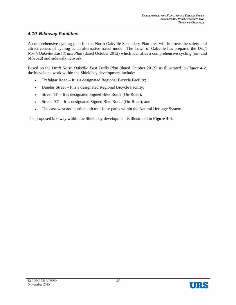
4.10 Bikeway Facilities A comprehensive cycling plan for the North Oakville Secondary Plan area will improve the safety and attractiveness of cycling as an alternative travel mode. The Town of Oakville has prepared the Draft North Oakville East Trails Plan (dated October 2012) which identifies a comprehensive cycling (on- and off-road) and sidewalk network. Based on the Draft North Oakville East Trails Plan (dated October 2012), as illustrated in Figure 4-2, the bicycle network within the Shieldbay development include:
• Trafalgar Road – It is a designated Regional Bicycle Facility;
• Dundas Street – It is a designated Regional Bicycle Facility;
• Street ‘B’ – It is designated Signed Bike Route (On-Road);
• Street ‘C’ – It is designated Signed Bike Route (On-Road); and
• The east-west and north-south multi-use paths within the Natural Heritage System. The proposed bikeway within the Shieldbay development is illustrated in Figure 4-4.

TTRRAANNSSPPOORRTTAATTIIOONN FFUUNNCCTTIIOONNAALL DDEESSIIGGNN SSTTUUDDYY SSHHIIEELLDDBBAAYY DDEEVVEELLOOPPMMEENNTTSS IINNCC..
TTOOWWNN OOFF OOAAKKVVIILLLLEE
Ref: 33017369.T0300 November 2013
24
Figure 4-4: Conceptual North Oakville East Trails and Bicycle Network

TTRRAANNSSPPOORRTTAATTIIOONN FFUUNNCCTTIIOONNAALL DDEESSIIGGNN SSTTUUDDYY SSHHIIEELLDDBBAAYY DDEEVVEELLOOPPMMEENNTTSS IINNCC..
TTOOWWNN OOFF OOAAKKVVIILLLLEE
Ref: 33017369.T0300 November 2013
25
4.11 On-Street Parking As noted in Section 3.2 – Road Classification and outlined in Table 3-3 – Roadway Classification and Characteristics, parking will generally be permitted on at least one side of all roads within the community except for laneways. The permitted on-street parking locations along the streets within the community have been identified to provide for optimum pedestrian and vehicular movement efficiency and safety. In general, the following placement guidelines were considered for identifying the appropriate side of the street for permitted on-street parking:
• Adjacent to schools, parks, open spaces, and significant pedestrian traffic generators to minimize pedestrian street crossing movements;
• Adjacent to medium/high residential, commercial, institutional or mixed-use developments to minimize pedestrian street crossing movements;
• Adjacent to the side of road with sidewalk to minimize pedestrian street crossing;
• Opposite side of the road from fire hydrants to minimize obstructed emergency accessibility;
• Outside of horizontal curves to maintain sightline visibility;
• Along the side of the road with the minimum number of intersecting roads and entrances; and
• Along the north and/or east side of the road to maximize snow melt from increased solar exposure.
The parking plan for the Shieldbay development conforms to the general provisions regarding on-street parking and is illustrated in Figure 4-5. Parking should be prohibited at locations where street elbow turns are present to provide improved visibility and mobility for large vehicles thought the length of the curves. The provision of on-street parking can function as an effective traffic calming measure by promoting reduced vehicle speeds as well as a buffer between pedestrians and vehicular traffic.

TTRRAANNSSPPOORRTTAATTIIOONN FFUUNNCCTTIIOONNAALL DDEESSIIGGNN SSTTUUDDYY SSHHIIEELLDDBBAAYY DDEEVVEELLOOPPMMEENNTTSS IINNCC..
TTOOWWNN OOFF OOAAKKVVIILLLLEE
Ref: 33017369.T0300 November 2013
26
Figure 4-5: Permitted On-Street Parking Plan

TTRRAANNSSPPOORRTTAATTIIOONN FFUUNNCCTTIIOONNAALL DDEESSIIGGNN SSTTUUDDYY SSHHIIEELLDDBBAAYY DDEEVVEELLOOPPMMEENNTTSS IINNCC..
TTOOWWNN OOFF OOAAKKVVIILLLLEE
Ref: 33017369.T0300 November 2013
27
4.12 Traffic Calming The roadways in the North Oakville community are designed with numerous traffic calming features to promote reduced vehicular speeds, discourage through traffic, minimize conflicts between road users, promote pedestrianization, and improve neighbourhood environment. The traffic calming plan for the community includes the following measures:
• Local street fabric as a basic grid pattern with basic connectivity but without extended continuous and uninterrupted local streets;
• Traffic control devices such as signals and stop signs. It is recognized that traffic signals and stop signs are not to be installed as traffic calming measures, as unwarranted traffic controls (from a volume or delay perspective) can actually increase vehicle speeds and create additional safety issues. They are only to be installed if the appropriate criteria are satisfied. In these cases, desirable traffic calming benefits (such as reduced speeds) can be achieved;
• Reduced pavement widths;
• Reduced building setbacks;
• On-street parking accommodations; and
• Sidewalk facilities on both sides of the road and space for either shared or dedicated on-street cycling.
Traffic calming identified for the Shieldbay development is in accordance to the practices recommended within Town of Oakville’s Traffic Calming Guidelines for New Developments document.
4.13 Transportation Functional Plan (Pavement Marking and Traffic Signage) The transportation functional plan for the Shieldbay development will be prepared during the engineering design stages of the development and shall be in accordance with the Town of Oakville’s guidelines. The transportation functional plan will include proposed pavement markings, locations for stop controls, as well as other key regulatory signs.