Random Sampling with Iterative Recovery for Millimeter ...
5
1 Random Sampling with Iterative Recovery for Millimeter-Wave Imaging Systems Hojatollah Zamani, Mohammad Fakharzadeh, Senior Member, IEEE, Arash Amini, Senior Member, IEEE, and Farokh Marvasti, Senior Member, IEEE Abstract—In this paper, an imaging methodology for mono- static millimeter-wave systems is introduced. When the measured object hologram is piece-wise smooth with sharp boundaries, both low-pass and high-pass components are present in a transform domain. Nevertheless, the edges are sparse in transform domain with respect to the image dimensions. It is shown that the down- sampling of the hologram with an appropriate rate determined by the sparsity level, includes the adequate information of all components for image reconstruction. Using random samples, an algorithm is proposed to recover all the sparse components, iteratively. Simulation results illustrate that a high-resolution recovery can be achieved. For instance, by using 20% of the randomly selected hologram samples, an image recovery with a PSNR of 20 dB is achieved and the object scan time is significantly reduced. The proposed methodology is applied to a practical imaging system operating at 30 GHz, where the results illustrate a successful reconstruction of the images. Index Terms—Iterative recovery, millimeter wave imaging, mono-static, random sampling. I. I NTRODUCTION Millimeter-wave imaging systems are widely used for differ- ent applications, such as concealed weapon detection (CWD), radar imaging for flaw detection, assisting driving or flying in foul weather, and non-destructive tests [1], [2]. Millimeter- waves naturally pass through the regular thin dielectric mate- rial, such as cloth, wood, and plastic. Thus, they are best suited for detection of denser materials such as metals, which reflect the wave. Interestingly, the image resolution of ∼ 1 - 10 mm, which is necessary for the detection of such objects is achieved in this band. The millimeter-wave imaging systems are cat- egorized into multi-static and mono-static classes. A multi- static system consists of multiple transmitters and receivers in different locations, where the transmitter antennas are turned on sequentially, while the receiving antennas measure the incoming wave simultaneously. In a mono-static system, a transmitter antenna and a receiver antenna are placed at the same location. One of the most conventional imaging methods in mono-static systems is the based on uniform scanning the object area by a transceiver pair in half-wavelength steps to avoid aliasing [3]. Depending on the object size, different number of hologram samples are required in a uniform scan. For instance, for a full human body scan (∼ 2 m), about 400 samples are required at 30 GHz (λ ∼ 1 cm). However, most of the images are sparse in a transform domain. Therefore, the number of samples required for a high-quality image reconstruction can be substantially lower than that of the uniform sampling. Authors are with the EE Department, Sharif University of Technology, Tehran, Iran.(Emails: [email protected], {fakharzadeh, aamini, marvasti}@sharif.edu) There are different strategies to reduce the number of samples. For instance, a nonuniform structure of linear arrays is designed in [4] to minimize the redundancy of linear arrays. A sparse sampling technique is introduced in [5], where two column arrays, one for TX and one for RX, are used with electronically switching antenna elements. In [6], the data redundancy in a multi-static imaging systems is studied. It is shown that the undesired distortion in reconstructed images can be compensated by applying the modified SAR back- projection algorithm. An array design called 1.5-D sparse is introduced in [7], where the elements positions are determined by applying a row-wise orthogonality constraint to gain from the diversity of information. Sparsity is a fundamental property in the reconstruction of images. For sparse images, the number of required samples to reconstruct the image can reach values far below the Nyquist rate. Theoretically, the number of required samples for the perfect reconstruction is twice the sparsity number (the number of non-zero coefficients in the sparse domain) and not twice the length of an interval that contains all non-zero coefficients [8]. There are two main categories of sparse images [9]. In the first category, the images are sparse in spatial domain such as synthetic aperture radar (SAR) imaging, whereas in the second category, the images are sparse in a transform domain (e.g., CWD hologram imaging). In the second category, a transform domain such as Discrete Fourier Transform (DFT) or Discrete Cosine Transform (DCT), is required for image reconstruction. To reconstruct these sparse images from the hologram samples, various algorithms based on compressive sensing are used, such as the total variation (TV) minimization technique [10]. Moreover, the dictionary-learning-based methods are used to adaptively estimate a sparsity domain and reconstruct the image [11]. Another class of recovery methods consists of iterative methods, which repeatedly apply a simple recovery procedure. These methods are designed such that the signal of interest becomes the fixed-point of a transformation, and then, by repeatedly applying this transformation, an approximation of the fixed-point signal is improved. Hence, if the initial point is properly selected, the output gradually converges to the opti- mum solution. One of the advantages of the iterative methods is that even when the sampling scheme is not invertible, it still converges to a fair approximation of the desired outcome, while most interpolation-based methods diverge in such cases [12]. Iterative method with side information of spectral support is investigated in [13]. An iterative method with adaptive thresholding (IMAT) is introduced in [8], to reconstruct the sparse signals with sub-Nyquist rate. The IMAT algorithm is shown to work with both structured and random samples.
Transcript of Random Sampling with Iterative Recovery for Millimeter ...

1
Random Sampling with Iterative Recovery forMillimeter-Wave Imaging Systems
Hojatollah Zamani, Mohammad Fakharzadeh, Senior Member, IEEE, Arash Amini, Senior Member, IEEE, andFarokh Marvasti, Senior Member, IEEE
Abstract—In this paper, an imaging methodology for mono-static millimeter-wave systems is introduced. When the measuredobject hologram is piece-wise smooth with sharp boundaries, bothlow-pass and high-pass components are present in a transformdomain. Nevertheless, the edges are sparse in transform domainwith respect to the image dimensions. It is shown that the down-sampling of the hologram with an appropriate rate determinedby the sparsity level, includes the adequate information of allcomponents for image reconstruction. Using random samples,an algorithm is proposed to recover all the sparse components,iteratively. Simulation results illustrate that a high-resolutionrecovery can be achieved. For instance, by using 20% of therandomly selected hologram samples, an image recovery with aPSNR of 20 dB is achieved and the object scan time is significantlyreduced. The proposed methodology is applied to a practicalimaging system operating at 30 GHz, where the results illustratea successful reconstruction of the images.
Index Terms—Iterative recovery, millimeter wave imaging,mono-static, random sampling.
I. INTRODUCTION
Millimeter-wave imaging systems are widely used for differ-ent applications, such as concealed weapon detection (CWD),radar imaging for flaw detection, assisting driving or flyingin foul weather, and non-destructive tests [1], [2]. Millimeter-waves naturally pass through the regular thin dielectric mate-rial, such as cloth, wood, and plastic. Thus, they are best suitedfor detection of denser materials such as metals, which reflectthe wave. Interestingly, the image resolution of ∼ 1−10 mm,which is necessary for the detection of such objects is achievedin this band. The millimeter-wave imaging systems are cat-egorized into multi-static and mono-static classes. A multi-static system consists of multiple transmitters and receivers indifferent locations, where the transmitter antennas are turnedon sequentially, while the receiving antennas measure theincoming wave simultaneously. In a mono-static system, atransmitter antenna and a receiver antenna are placed at thesame location. One of the most conventional imaging methodsin mono-static systems is the based on uniform scanning theobject area by a transceiver pair in half-wavelength steps toavoid aliasing [3]. Depending on the object size, differentnumber of hologram samples are required in a uniform scan.For instance, for a full human body scan (∼ 2 m), about 400samples are required at 30 GHz (λ ∼ 1 cm). However, mostof the images are sparse in a transform domain. Therefore,the number of samples required for a high-quality imagereconstruction can be substantially lower than that of theuniform sampling.
Authors are with the EE Department, Sharif University of Technology,Tehran, Iran.(Emails: [email protected], {fakharzadeh, aamini,marvasti}@sharif.edu)
There are different strategies to reduce the number ofsamples. For instance, a nonuniform structure of linear arraysis designed in [4] to minimize the redundancy of linear arrays.A sparse sampling technique is introduced in [5], where twocolumn arrays, one for TX and one for RX, are used withelectronically switching antenna elements. In [6], the dataredundancy in a multi-static imaging systems is studied. It isshown that the undesired distortion in reconstructed imagescan be compensated by applying the modified SAR back-projection algorithm. An array design called 1.5-D sparse isintroduced in [7], where the elements positions are determinedby applying a row-wise orthogonality constraint to gain fromthe diversity of information.
Sparsity is a fundamental property in the reconstruction ofimages. For sparse images, the number of required samples toreconstruct the image can reach values far below the Nyquistrate. Theoretically, the number of required samples for theperfect reconstruction is twice the sparsity number (the numberof non-zero coefficients in the sparse domain) and not twicethe length of an interval that contains all non-zero coefficients[8]. There are two main categories of sparse images [9]. In thefirst category, the images are sparse in spatial domain such assynthetic aperture radar (SAR) imaging, whereas in the secondcategory, the images are sparse in a transform domain (e.g.,CWD hologram imaging). In the second category, a transformdomain such as Discrete Fourier Transform (DFT) or DiscreteCosine Transform (DCT), is required for image reconstruction.To reconstruct these sparse images from the hologram samples,various algorithms based on compressive sensing are used,such as the total variation (TV) minimization technique [10].Moreover, the dictionary-learning-based methods are used toadaptively estimate a sparsity domain and reconstruct theimage [11].
Another class of recovery methods consists of iterativemethods, which repeatedly apply a simple recovery procedure.These methods are designed such that the signal of interestbecomes the fixed-point of a transformation, and then, byrepeatedly applying this transformation, an approximation ofthe fixed-point signal is improved. Hence, if the initial point isproperly selected, the output gradually converges to the opti-mum solution. One of the advantages of the iterative methodsis that even when the sampling scheme is not invertible, itstill converges to a fair approximation of the desired outcome,while most interpolation-based methods diverge in such cases[12]. Iterative method with side information of spectral supportis investigated in [13]. An iterative method with adaptivethresholding (IMAT) is introduced in [8], to reconstruct thesparse signals with sub-Nyquist rate. The IMAT algorithm isshown to work with both structured and random samples.

2
��
��
�
�
��
Transceiver
�
Fig. 1. Configuration of the mono-static imaging system.
In this paper, an imaging methodology based on randomsampling and iterative hologram recovery for millimeter waveimaging systems is introduced. In this method, a randomsubset of the discretized points are selected. Therefore, theimaging process is very fast. Next, a tailored iterative al-gorithm is proposed to estimate the missing samples beforerecovering the image. Unlike [12], the proposed iterativemethod needs to solve a non-linear inverse problem.
This paper is organized as follows. In Section II the systemmodel of a mono-static imaging device is presented. Then, thesparse imaging approach and the iterative recovery strategy arepresented in Section III. The simulation and measured resultsand discussions are provided in Section IV. Finally, the paperis concluded in Section V.
II. SYSTEM MODEL
The mono-static imaging system is modeled as shown inFig. 1, where the transceiver antenna elements measure thereflected signal from the object over a 2-D plane parallel tothe object plane. Assume that the transceiver is located at(x′, 0, z′) in x′-z′ plane, while the point (x, y0, z) in the objectplane (x-z) is being scanned. If the reflected wave from f(x, z)travels in a linear, isotropic, homogeneous, and non-dispersivemedium, then, all components of the electric and magneticfields are fully described by a single scalar wave equation [14].The scattered field at the transceiver is a linear combination ofthe reflected waves from all the object points as stated in [15].In practice, the scanner produces a finite number of samples.Hence, a discrete model for the imaging problem is required.The planes of the transceiver and the object are discretizedinto finite points. Let us consider the matrices S and F as thediscretized planes of transceiver with M ×N points, and theobject plane with P ×Q points, respectively. Then, s
S[m,n] =
P∑p=1
Q∑q=1
F[p, q]e−j2kr[m,n,p,q], (1)
where r[m,n, p, q] =√
(m− p)2 + y20 + (n− q)2 is theEuclidean distance between the transceiver position [m,n] andthe object point [p, q]. Moreover, k is the wavenumber. Toestimate the hologram of the object, different approaches arepresented in the literature such as [15], [9]. One commonmethod is to use the generalized focusing technique (GSAFT)[15], which reconstructs the hologram as follows
f(x, z) = F−1{F{s(x, z)} e−jkyy0}, (2)
where ky =√4k2 − kx − kz . The operators F{·} and
F−1{·} represent the 2-D Fourier transform and its 2-D
inverse, respectively. In this approach, the final estimatedimage is the absolute value of the inverse Fourier transformof phase shifted measurements in Fourier domain.
III. PROPOSED IMAGING METHOD
A. Recovery problem
In the conventional imaging approach, the transceiver scansthe whole object uniformly with the Nyquist rate equal toλ/2 to avoid aliasing, where λ is the carrier wavelength.This approach is not time-efficient, since a large amount ofsamples is generated. On the other hand, usually the imagesare sparse in a transform domain, such as Fourier or Waveletdomains. Hence, the minimum number of the samples requiredto recover the sparse components is far less than the numberof samples obtained from the uniform sampling. In addition, itis shown that the random sampling preserves the informationof all components in the sparse domain. In this work, theFourier domain is considered as the sparse domain and randomsampling scheme by a known rate related to the number ofsparse coefficients is used. The detail of the proposed imagingmethod is depicted in Fig. 2, where a random binary mask(0/1) with the size of the discretized transceiver plane is usedto reduce the processing samples. The transceiver follows themask pattern and scans any point where its correspondingvalue is equal to 1. After scanning the object, a matrix ofthe measured hologram data is formed with missing pointsin matrix (Ss). The hologram data in this matrix belongto the spatial domain. To recover the missing samples ofthe hologram, the proposed algorithm is applied. Finally, therecovered hologram is processed using the GSAFT method toestimate the final image. In fact, a sparse matrix of data inFourier domain is formed such that its projected samples inspatial domain are equal to the measured random samples.Mathematically, the following optimization problem is formed
minS′‖F{S′}‖0 subject to PM (S′) = PM (S) (3)
where ‖ · ‖0 is the `0-norm, which is equal to the numberof non-zero coefficients. PM (·) is an operator with maskM (i.e. PM (S) = M � S, where � is the Hadamardproduct). Although (3) gives the desired solution, this is anon-deterministic polynomial time problem, which is compu-tationally intensive. Hence, based on the theory of compressedsensing, the `0-norm is replaced by a sub-optimal convexrelaxation approach, so the problem can be solved using `1-norm minimization [16], or
minS′‖F{S′}‖1 subject to PM (S′) = PM (S) (4)
The Basis Pursuit (BP) [17] and LASSO [18] algorithms aretwo common methods for solving problems similar to (4). Inthis paper, instead, an iterative algorithm is proposed, whichis described in details in the following section.
B. Proposed Algorithm
To recover the hologram from its samples, an iterativemethod is employed, where its goal is to construct the in-version of the distortion operator by its samples [12]. The

3
IMAT
Mask Imaging Hologram Samples Hologram Rec. Est. Image
��
��
�
�
��
Transceiver
�ProposedAlgorithm
Mask Imaging Samples Holog. Rec. Recovery
Ss S
Fig. 2. Proposed imaging method. The green circles in Mask corresponds to the sampling points.
µD{·}
µy
xk−
xk+1
Fig. 3. The block diagram of the iterative method at (k + 1)th iteration.
iterative recovery methods are tied to the fixed point theoryin mathematics. The block diagram of the iterative recoverymethod is presented in Fig. 3. As it is shown, the processof signal recovery, x, from its measured samples, y, withdistortion operator D{·} at iteration (k + 1) is described by
xk+1 = xk + µ(y −D{xk}
)y = D{x}+ n
x0 = 0
where µ is the relaxation parameter and n is the noise vector.Similar to the sparse recovery algorithms, the proposed
approach is based on recovering the hologram iteratively.At each iteration, first the image is transformed into theFourier domain (the sparsity domain). Next, the thresholdingoperator is applied to enforce the sparsity constraint, andthen, the inverse Fourier transform is used to return to thepixel domain. Finally, the pixel values are replaced with theoriginal values wherever available (the projection step). Hence,the operator D{·} in the proposed algorithm consists of thethresholding step in the sparsity domain and replacing themeasured samples in the pixel domain. By iteratively enforcingthe sparsity constraint in the Fourier domain and the consis-tency constraint in the pixel domain, the missing samples aregradually recovered. In other words, after the iterative methodconverges, the recovered image satisfies both constraints. Thus,if the number of samples is sufficient to uniquely represent theimage, the recovered image shall coincide with the originalone. In other cases, the recovered image represents a sparseapproximation of the original image. The block diagram ofthe proposed method is presented in Fig. 4. The thresholdingoperator T on matrix X with entries xij and threshold valueτ is defined as
xij = 0 if |xij | < τ, xij = xij otherwise. (5)
Remark 1. To select the sparse components gradually, asuitable technique is to decrease the threshold level τ as theiteration number increases. Hence, an exponential thresholdlevel is used
τk = βe−αk, (6)
Input (Ss)
Output (S)
F T
F−1
P
Fig. 4. The block diagram of the proposed algorithm. The operators F , T ,F−1, and P stand for the Fourier transform, the thresholding operator, theinverse Fourier transform and the projection operator, respectively.
TABLE ITHE RECONSTRUCTION PSNR IN DB AND THE SSIM METRIC FOR FIG. 5
Rate 5% (left col.) 20% (middle col.) 80% (right col.)Metric PSNR SSIM PSNR SSIM PSNR SSIM
GSAFT 12.12 0.0321 15.84 0.0730 21.28 0.1840DMAS 12.64 0.0629 14.97 0.2799 19.28 0.8920
Proposed 16.01 0.0425 21.99 0.3295 23.62 0.8101
where β = ‖F{X0}‖∞, and α ∈ (0, 1). Parameter β is setto the largest coefficient to assure that there is at least onecoefficient to be picked up in the first iteration.
The projection operator, which maps the measured samplesto their locations is
PM{Ss,Z} = Ss + (1−M)�Z, (7)
The projection PM{Ss,Z} returns a matrix, whose entriesare selected from Z (the IFFT of (5)) if the correspondingentries in M are zero, otherwise they are selected from Ss.The algorithm terminates when the relative variation of thereconstructed images between the two consecutive iterationsis smaller than ε. The parameter ε is determined empirically.
IV. SIMULATION AND EXPERIMENTAL RESULT
In this section, the proposed method is examined andcompared with the conventional methods such as GSAFT [15],FFT-SAR [19], and delay multiply and sum (DMAS) [20].The mono-static imaging system operates at 30 GHz, so theminimum sampling space is λ/2 = 0.5 cm. The distancebetween the transceiver and object planes is equal to 100 cm.Also, both planes are discretized to 100 × 100 grid points.The threshold decay factor is set to α = 0.1. To have a faircomparison, the structural similarity index measure (SSIM)
4
(a) (b)
(c1) (c2) (c3)
(d1) (d2) (d3)
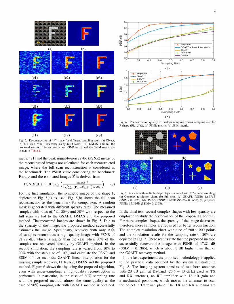
(e1) (e2) (e3)Fig. 5. Reconstruction of “F” shape for different sampling rates. (a) Object,(b) full scan result. Recovery using (c) GSAFT, (d) DMAS, and (e) theproposed method. The reconstruction PSNR in dB and the SSIM metric areshown in Table I.
metric [21] and the peak signal-to-noise ratio (PSNR) metric ofthe reconstructed images are calculated for each reconstructedimage, where the full scan reconstruction is considered asthe benchmark. The PSNR value considering the benchmarkFM×N and the estimated images F is derived from
PSNR(dB) = 10 log10
(max(F)2(√∑
i,j(Fi,j−Fi,j)2)/(MN)
). (8)
For the first simulation, the synthetic image of the shape F,depicted in Fig. 5(a), is used. Fig. 5(b) shows the full scanreconstruction as the benchmark for comparison. A randommask is generated with different sparsity rates. The measuredsamples with rates of 5%, 20%, and 80% with respect to thefull scan are fed to the GSAFT, DMAS and the proposedmethod. The recovered images are shown in Fig. 5. Due tothe sparsity of the image, the proposed method successfullyestimates the image. Specifically, recovery with only 20%of samples reconstructs a high quality image with PSNR of21.99 dB, which is higher than the case when 80% of thesamples are recovered directly by GSAFT method. In thesecond simulation, the sampling rate is varied from 10% to90% with the step size of 10%, and calculate the PSNR andSSIM of five methods: GSAFT, linear interpolation for themissing sample recovery, FFT-SAR, DMAS and the proposedmethod. Figure 6 shows that by using the proposed algorithm,even with under-sampling, a high-quality reconstruction isperformed. In particular, in the case of 30% sampling ratewith the proposed method, almost the same quality as thecase of 90% sampling rate with GSAFT method is obtained.
0.1 0.2 0.3 0.4 0.5 0.6 0.7 0.8 0.9
Sampling Rate
12
14
16
18
20
22
24
PS
NR
(dB
)
Proposed
GSAFT + linear Interpolation
GSAFT
FFT-SAR
DMAS
(a)
0.1 0.2 0.3 0.4 0.5 0.6 0.7 0.8 0.9
Sampling Rate
0
0.2
0.4
0.6
0.8
1
SS
IM
Proposed
DMAS
GSAFT
FFT-SAR
(b)Fig. 6. Reconstruction quality of random sampling versus sampling rate forF shape (Fig. 5(a)), (a) PSNR metric, (b) SSIM metric.
(a) (b)
(c) (d) (e)Fig. 7. A scene with multiple shape objects scanned with 20% undersampling.(a) Complex resolution chart, (b) full scan, (c) GSAFT, PSNR: 12.57dB(SSIM= 0.0325), (d) DMAS, PSNR: 9.52dB (SSIM= 0.0567), (e) proposedPSNR: 17.31dB (SSIM= 0.1365).
In the third test, several complex shapes with low sparsity areemployed to study the performance of the proposed algorithm.For more complex shapes, the sparsity of the image decreases,therefore, more samples are required for better reconstruction.The complex resolution chart with size of 200 × 200 pointsand the simulation results for the sampling rate of 20% aredepicted in Fig. 7. These results state that the proposed methodsuccessfully recovers the image with PSNR of 17.31 dB(SSIM = 0.1365), which is about 5 dB higher than that ofthe GSAFT recovery method.
In the last experiment, the proposed methodology is appliedto the practical data obtained by the system illustrated inFig. 8. The imaging system consists of two horn antennaswith 20 dB gain at Ka-band (26.5 − 40 GHz) used as TXand RX antennas, an RF amplifier with 18 dB gain anda mechanical positioner, which moves the antennas to scanthe object in Cartesian plane. The TX and RX antennas are

5
Fig. 8. Practical setup for imaging at 30 GHz. The shape is parallel to thetransceiver plane.
(a) (b)
(c) (d) (e)Fig. 9. Measurement results. (a) Original object, (b) full scan, (c) GSAFTwith 40% sampling rate, PSNR: 14.25 dB (SSIM= 0.2424), (d) DMAS with40% sampling rate, PSNR: 13.67dB (SSIM= 0.2596), (e) proposed methodwith 40% sampling rate, PSNR: 25.02dB (SSIM = 0.6583).
connected to HP8722ES network analyzer, which transmitsand receives millimeter-wave signals. The whole system isplaced inside an anechoic chamber, where undesired reflectorsare absorbed. The distance between the transceiver and objectplanes is 30 cm. The horn antennas follow the binary mask ofsize 55 × 55 for imaging. The scanning time at each sensornode (essentially each pixel) takes 0.1 ms. The measuredreceived signal is saved in the computer and then the proposedalgorithm is applied. The sampling rate of 40% is used in thisexperiment, where a metal cross object is used. The resultsare depicted in Fig. 9. The proposed method successfullyreconstructs the image from a subset of samples with a PSNRof 25.02 dB.
The execution time of the proposed algorithm on imagessize of 100×100 is measured as 35.1 ms on average over 1000independent runs with varying sampling rates. For a typicalcase, consider a 30% undersampling rate which translates intodropping 3000 pixels. This saves us 300 ms of scanning time,while our method adds 35.1 ms to the overall computationtime. The algorithm was implemented in MATLAB 2019b ona workstation with Intel(R) Core(TM) i7-4930K CPU @3.40GHz(12 CPUs) and 16 GB RAM. On this workstation forthe sampling rate of 20% the execution time of reconstructionprocess for GSAFT, proposed approach, and DMAS are 3.12sec, 3.39 sec and 97.70 sec, respectively.
V. CONCLUSION
In this paper, an imaging methodology for the mono-staticmillimeter wave systems was introduced, based on random
sampling with the specific rates related to the sparsity of thehologram in a transform domain. To achieve a high resolutionrecovery, an iterative algorithm is proposed to recover themissing samples of the hologram. Simulation results on thesynthetic shapes as well as the experimental data proved thesuccessful performance of the proposed imaging and recoverymethods. For example, it was shown that by using only 20% ofthe regular samples, the imaging process is performed faster.Furthermore, the achieved PSNR in the reconstruction is over20 dB, which is higher than the case where 80% of samplesare processed with the direct GSAFT method.
REFERENCES
[1] S. S. Ahmed et al., “A Novel Fully Electronic Active Real-Time ImagerBased on a Planar Multistatic Sparse Array,” IEEE Trans. Microw.Theory Tech., vol. 59, no. 12, pp. 3567–3576, 2011.
[2] T. S. Rappaport et al., “Wireless communications and applications above100 ghz: Opportunities and challenges for 6g and beyond,” IEEE Access,vol. 7, pp. 78 729–78 757, 2019.
[3] M. C. Kemp, “Millimetre wave and terahertz technology for detectionof concealed threats - a review,” in 2007 Joint 32nd InternationalConference on Infrared and Millimeter Waves and the 15th InternationalConference on Terahertz Electronics, 2007, pp. 647–648.
[4] H. Van Trees, Detection, Estimation, and Modulation Theory, OptimumArray Processing. Wiley, 2002.
[5] T. E. H. David M. Sheen, “Reconstruction techniques for sparse multi-static linear array microwave imaging,” Proc.SPIE, vol. 9078, 2014.
[6] M. Kazemi et al., “Spectral redundancy compensation in multi-staticmillimeter-wave imaging,” IEEE Trans. on Circuits and Systems II:Express Briefs, vol. 65, no. 5, pp. 687–691, May 2018.
[7] H. Zamani and M. Fakharzadeh, “1.5-d sparse array for millimeter-waveimaging based on compressive sensing techniques,” IEEE Trans. onAntennas and Propagation, vol. 66, no. 4, pp. 2008–2015, April 2018.
[8] F. Marvasti and et al., “A unified approach to sparse signal processing,”EURASIP Journal on Advances in Signal Processing, vol. 2012, no. 1,p. 44, Feb 2012.
[9] Q. Cheng, A. Alomainy, and Y. Hao, “Compressive millimeter-wavephased array imaging,” IEEE Access, vol. 4, pp. 9580–9588, 2016.
[10] Y. Wang, J. Yang, W. Yin, and Y. Zhang, “A new alternating minimiza-tion algorithm for total variation image reconstruction,” SIAM Journalon Imaging Sciences, vol. 1, no. 3, pp. 248–272, 2008.
[11] C. Jiang, Q. Zhang, R. Fan, and Z. Hu, “Super-resolution ct imagereconstruction based on dictionary learning and sparse representation,”Scientific reports, vol. 8, no. 1, p. 8799, 2018.
[12] A. Amini and F. Marvasti, “Convergence analysis of an iterative methodfor the reconstruction of multi-band signals from their uniform andperiodic nonuniform samples,” Sampling Theory in Signal and ImageProcessing (STSIP), vol. 7, no. 2, pp. 109–112, 2008.
[13] F. Marvasti, “Spectral analysis of random sampling and error freerecovery by an iterative method,” Transactions of IECE of Japan. SectionE, vol. 69, no. 2, pp. 79–82, 1986.
[14] J. W. Goodman, Introduction to fourier optics. McGraw-Hill, 1996.[15] D. M. Sheen, D. L. McMakin, and T. E. Hall, “Three-dimensional
millimeter-wave imaging for concealed weapon detection,” IEEE Trans.Microw. Theory Tech., vol. 49, no. 9, pp. 1581–1592, 2001.
[16] E. J. Candes, J. K. Romberg, and T. Tao, “Stable signal recovery fromincomplete and inaccurate measurements,” Communications on pure andapplied mathematics, vol. 59, no. 8, pp. 1207–1223, 2006.
[17] S. S. Chen, D. L. Donoho, and M. A. Saunders, “Atomic decompositionby basis pursuit,” SIAM review, vol. 43, no. 1, pp. 129–159, 2001.
[18] R. Tibshirani, “Regression shrinkage and selection via the lasso,” Jour-nal of the Royal Statistical Society: Series B (Methodological), vol. 58,no. 1, pp. 267–288, 1996.
[19] M. Soumekh, “A system model and inversion for synthetic aperture radarimaging,” IEEE Trans. on Image Proc, vol. 1, no. 1, pp. 64–76, Jan 1992.
[20] H. Been Lim, N. Thi Tuyet Nhung, E. Li, and N. Duc Thang, “Confocalmicrowave imaging for breast cancer detection: Delay-multiply-and-sum image reconstruction algorithm,” IEEE Transactions on BiomedicalEngineering, vol. 55, no. 6, pp. 1697–1704, June 2008.
[21] Zhou Wang et al., “Image quality assessment: from error visibility tostructural similarity,” IEEE Trans. on Image Processing, vol. 13, no. 4,pp. 600–612, April 2004.