RAND - apps.dtic.mil · performance considerations, although it may be necessary to refan for...
95
RAND Next-Generation Attack Fighter Design Tradeoffs and Notional System Concepts Daniel P. Raymer 50. <* uric QUALITY INSPECTED S Project AIR FORCE 19 4 6-1996 DISTRIBUTION STATEMENT A Approved for public release; Distribution Unlimited
Transcript of RAND - apps.dtic.mil · performance considerations, although it may be necessary to refan for...
RAND
Next-Generation Attack Fighter Design Tradeoffs and Notional System Concepts
Daniel P. Raymer
50. <* uric QUALITY INSPECTED S
Project AIR FORCE 19 4 6-1996
DISTRIBUTION STATEMENT A
Approved for public release; Distribution Unlimited

THIS DOCUMENT IS BEST
QUALITY AVAILABLE. THE
COPY FURNISHED TO DTIC
CONTAINED A SIGNIFICANT
NUMBER OF PAGES WHICH DO
NOT REPRODUCE LEGIBLY.

The research reported here was sponsored by the United States Air Force under Contract F49642-96-C-0001. Further information may be obtained from the Strategic Planning Division, Directorate of Plans, Hq USAF.
Library of Congress Cataloging in Publication Data
Raymer, Daniel P. Next generation attack fighter: design tradeoffs and notional
system concepts / Daniel P. Raymer. p. cm.
"Project AIR FORCE." "Prepared for the United States Air Force." "MR-595-AF." Includes bibliographical references. ISBN 0-8330-2406-X (alk. paper) 1. Attack planes-United States-Design and construction.
2. Fighter planes-United States-Design and construction. 3. Attack planes-Specifications-United States. 4. Fighter planes-Specifications-United States. 5. Short take-off and landing aircraft-Design and construction. I. RAND Corporation. II. Project AIR FORCE (U.S.) III. United States. Air Force. IV. Title. TL685.3.R38 1996 358.4'383'0973—dc20 96-23122
CIP
© Copyright 1996 RAND
All rights reserved. No part of this book may be reproduced in any form by any electronic or mechanical means (including photocopying, recording, or information storage and retrieval) without permission in writing from RAND.
RAND is a nonprofit institution that helps improve public policy through research and analysis. RAND's publications do not necessarily reflect the opinions or policies of its research sponsors.
Published 1996 by RAND 1700 Main Street, P.O. Box 2138, Santa Monica, CA 90407-2138
RAND URL: http://www.rand.org/ To order RAND documents or to obtain additional information, contact Distribution Services: Telephone: (310) 451-7002; Fax: (310) 451-6915; Internet: [email protected]

RAND
Next-Generation Attack Fighter Design Tradeoffs and Notional System Concepts
Daniel P. Raymer
Prepared for the United States Air Force
50 *
Project AIR FORCE 19 4 6-1996
Approved for public release; distribution unlimited
Preface
This report discusses results of research conducted by RAND on the definition of technical "design-to" requirements for a next-generation attack fighter (NGAF). The research focused on the range and performance needs of an NGAF and the tradeoffs involved with satisfying tri-service needs. The report offers analytical evaluations of many key issues involving a new attack fighter.
This research was sponsored by the Combat Forces Requirements Division, Office of the Deputy Chief of Staff for Plans and Operations (AF/XO), Headquarters, United States Air Force. It was performed as part of the Future Aircraft Technologies Project within the Force Modernization and Employment Program of Project AIR FORCE. It should be of interest to the fighter development community and to the Joint Attack Strike Technology (JAST) program office personnel. This research is closely related to JAST and has been reviewed by JAST personnel, but it is neither directly associated with nor sponsored by the JAST Program Office.
Concept design and trade studies described herein were done largely between June 1994 and February 1995. Preliminary and final results were widely briefed to government and industry personnel between October 1994 and May 1995. This report documents those results.
Project AIR FORCE, a division of RAND, is the Air Force federaUy funded research and development center (FFRDC) for studies and analyses. It provides the Air Force with independent analyses of policy alternatives affecting the development, employment, combat readiness, and support of current and future aerospace forces. Research is being performed in three programs: Strategy and Doctrine; Force Modernization and Employment; and Resource Management and System Acquisition.
In 1996, Project AIR FORCE is celebrating 50 years of service to the United States Air Force. Project AIR FORCE began in March 1946 as Project RAND at Douglas Aircraft Company, under contract to the Army Air Forces. Two years later, the project became the foundation of a new, private nonprofit institution to improve public policy through research and analysis for the public welfare and security of the United States—what is known today as RAND.

Contents
Preface iii
Figures vii
Tables ix
Summary xi
Acknowledgments xv
Glossary xvii
1. INTRODUCTION 1 Study Objectives 2 Reliability of Results 2
2. APPROACH 3
3. BASEPOINT CONCEPT DESIGN AND ANALYSIS 5 Initial Requirements 5 Basepoint Concept Description 6 Basepoint Concept Analysis Summary 8 Basepoint Mission Sizing 10 Range Analysis with Overload Internal Fuel 13 Basepoint Performance Analysis 14
4. RANGE/PAYLOAD/DESIGN TRADE STUDIES 16 Basepoint Range Trades 16 Basepoint Payload Trades 18 Design Trades 21 Technology Trades 22 Engine Trades 24 Design Trades Summary 26
5. JOINTSERVICE OPTIONS STUDY 28 Overview 28 Two-Way Modularity Study 30 Two-Way Study Analysis Assumptions 32 Two-Way Study Results 34 "Soft-Cat" and "Ski-Jump" Carrier Operation 37 Three-Way Modularity Study 39
6. CONCLUSIONS 42
Appendix A. Basepoint Design Concept 49 B. Sizing, Range, and Payload Trades 61 C. Basepoint Performance Analysis 72 D. Joint Service Options Weight Results 77
References 83

Figures
2.1. Research Methodology 3 3.1. RAND NGAF Notional Basepoint Design Concept 7 3.2. NGAF Notional Design Concept 8 3.3. Lift-to-Drag Ratios 10 3.4. RAND NGAF Sizing Mission 12 4.1. Effect of Range: Design Takeoff Gross Weight 17 4.2. Effect of Range: With "Internal-External" Fuel 17 4.3. Basepoint Weapons Bay: JDAM, MK-83, and TMD 19 4.4. Trade Study: Internal 2,000 lb JDAM 19 4.5. Tailless Trade Study 23 4.6. Lift-to-Drag Ratios with Laminar Flow Technology 25 4.7. Parametric Design Optimization 25 5.1. Joint-Service Design Study Methodology 30 5.2. Weights Results Summary (Unsized) 34 5.3. Range Results Summary 36 5.4. "Soft-Cat" Launch Approach 37 5.5. "Three-Way" Modularity Study 40
A.l. RAND NGAF Notional Baseline Design Concept 50 A.2. Parasitic Drag 56 A.3. Drag-Due-to-Lift Factor 57 A.4. Drag Polars 57 A.5. Lift-to-Drag Ratios 58 A.6. Maximum Lift 58 B.l. Sizing Sensitivity: Parasitic Drag 64 B.2. Sizing Sensitivity: Drag Due to Lift 65 B.3. Sizing Sensitivity: Specific Fuel Consumption 65 B.4. Sizing Sensitivity: Dead Weight (e.g., change in We) 66 B.5. Sizing Sensitivity: Payload Weight 66 B.6. Effect of Limit Load Factor on Empty Weight 67 B.7. Sizing Sensitivity: Limit Load Factor 67 B.8. FourMK-82s 69 B.9. External Carriage of Six 1,000 lb JDAMs 69
B.10. External Carriage of Four 2,000 lb JDAMs 70 B.ll. SixMK-82s 70 B.12. FourTMDs 71 B.13. Weapons Carriage Capabilities 71 C.l. Flight Envelope 73 C.2. Cruise Performance (Range Optimization) 73 C.3. Rate of Climb . 74 C.4. Rate of Climb at Overload Takeoff Weight 74 C.5. Instantaneous Turn Rate 75 C.6. Sustained Turn Rate 75 C.7. Sustained Turn Rate: Navy Ground Rules 76

Tables
3.1. Initial Design Goals 6 3.2. Basepoint Weights Results 11 3.3. Weight Savings Through Use of Composite Materials 12 3.4. Performance Results 15 4.1. Payload Trade Studies 22 5.1. CTOL/Carrier/STOVL Factors and Assumptions 32 5.2. STOVL Design Assumptions 33 5.3. Mission Results—Fixed Takeoff Gross Weight 35 5.4. Resizing Results—550 nmi Mission Radius 36 5.5. Mission Results with Overload Fuel 36 5.6. "Three-Way" Modularity Factors and Assumptions 40 5.7. "Three-Way" Modularity Results 41 6.1. Analysis Summary: Mission Radius (nmi) and Percentage
Reduction vs. Service-Optimization Design 43 6.2. Analysis Summary: Mission Radius (nmi) and Percentage
Reduction vs. Service-Optimized Design 43 6.3. Recommended Minimum Design Requirements 46
A.l. Inlet Recovery 59 A.2. Basepoint Weights Analysis Assumptions 59 A.3. Basepoint Weights Results 60 B.l. Baseline Sizing Results 61 D.I. CV-CTOL Group Weight Statement 78 D.2. Air Force CV-CTOL Derivative Group Weight Statements 79 D.3. STOVL Group Weight Statement 80 D.4. Air Force STOVL-Derivative Group Weight Statement 81

Summary
Current Air Force, Navy, and Marine Corps fighter/attack aviation aircraft are 1970s-vintage designs that will reach the end of their service lives in the early part of the next century. Although the Air Force is developing the highly advanced F-22, it cannot be used to replace all current assets, especially F-16s, simply because of cost. A "low-end" complementary design is required, much as the F-16 was the "low" of a "high-low mix" with F-15s. The Navy and Marine Corps have no all-new fighter/attack design in development. The F-18 E/F will have improved characteristics compared to earlier versions, but it does not fully use newer technologies and specifically it will not have the desired and attainable levels of stealth and range-payload performance, nor will it offer next- generation short takeoff, vertical landing (STOVL) capability for the Marine Corps.
This report presents the results of research into the tradeoffs in requirements specification for a next-generation attack fighter, answering in depth such critical questions as
• Is STOVL a viable approach for tri-service capability?
• What is the effect of providing space for a second seat?
• How much range must we give up to carry two more stores?
This research was conducted by developing and analyzing a representative notional design concept for a next-generation attack fighter (NGAF), then conducting numerous trade studies of range, performance, payload, and technologies. This was followed by study of alternative approaches to attaining tri-service capability.
This study concludes that a single-seat, single-engine fighter that uses a near- term engine and the currently available advanced technologies could provide a substantial advantage in range, payload, and signature over current aircraft. With careful requirements specification and design, it appears quite feasible to meet the fundamental needs of the Air Force, Navy, and Marine Corps with a highly common production line.
Judging by the results of this study, it appears that the key desires of all three services can best be met with a highly common "two-way" modularity approach

using STOVL for both the Marine Corps and Navy. By providing a "soft-cat" capability to use a slight assist from the catapult, or by using a ski-jump takeoff, the Navy could operate at the increased takeoff weights needed for maximum range and payload. The Air Force derivative could then be a highly common production line variation with the STOVL lift equipment removed, some changes to mission avionics, and virtually everything else the same. Also, the space left empty when a lift engine or fan is removed could be used for a second seat for training aircraft, with no change to primary structure.
Although a more aggressive "three-way" modularity approach with a different production for each service, with differing wings, fuselage structure, and other
components, would probably offer a bit more range, such an approach does not seem to be mandatory for a successful tri-service aircraft, and, because it reduces commonality, it introduces additional costs and risks in the development, production, and support of such an aircraft.
A refanned engine does not seem to be required for range, payload, or performance considerations, although it may be necessary to refan for infrared (IR) signature reasons. Also, the better fuel economics of a refanned engine may, in the long run, pay for the development costs.
A trade study on size of the internal air-to-ground weapons (1,000 or 2,000 pound joint direct attack munitions (JDAMs) shows a sufficient weight/range effect that the smaller weapons would be preferred. However, many in the Naval community feel that the 2,000 pound weapons are mandatory. Lethality effectiveness studies beyond the scope of this report will be required to settle this issue, but data in this report can be used to assess the weight—and from that, the cost—of the alternatives.
In addition to the internal bay capability for two 1,000 pound (or one 2,000 pound) weapons, internal bays for two AIM-120-class air-to-air weapons and external hardpoints for four 2,000 pound or six 1,000 pound weapons should and could be provided.
This study strongly supports a design approach using "internal-external" fuel, in which extra fuel volume is designed into the aircraft but not "counted" in baseline calculations for midmission maneuverability and maximum load factor structural allowances. This is analogous to the traditional practice of designing a fighter for a moderate-range mission with full maneuver requirements, then adding external fuel for long range and accepting that the aircraft will not have full maneuvering capabilities for these long-range missions. To take advantage of this capability in a new aircraft development, requirements must be fully and properly defined for both "design weight" and "maximum overload" weight missions.

Traditional allowances for even further unspecified growth must be curtailed in the definition of requirements for the baseline aircraft, or the weight will grow to an unacceptable amount.
The study of potential emerging technologies indicates that both tailless and laminar-flow control seem to offer real benefits for such an advanced fighter. As both these technologies are immature, they should not be considered for inclusion in a baseline design at this time, but they should be studied and a decision to include them should be deferred. With suitable funding and demonstration, both technologies could probably be ready for use in the 2000- 2005 timeframe.
To summarize, this study indicates that a single-seat, single-engine fighter using a powerplant typical of a near-term derivative engine, and using aircraft technologies only slightly advanced over current levels, could provide a substantial advantage in range, payload, and signature over current strike aircraft, and that the best approach for attainment of tri-service capabilities at a minimum risk is through the use of STOVL for both the Navy and the Marine Corps.

Acknowledgments
Numerous individuals from many organizations reviewed and contributed valuable expertise to the notional design analysis as described in this report. Particular thanks go to F. O'Brimski, L. Trobaugh, and D. Cates of the Naval Air Systems Command; W. O'Connor of the Air Force Wright Aeronautical Laboratory; J. Eney of the Naval Air Warfare Center (Warminster); Colonel G. Goodwin and Lieutenant Colonel K. Konwin of the Joint Advanced Strike Technology Program Office; W. D. O'Neil and M. M. McCrea of the Center for Naval Analyses; and D. Sondee and W. Boudreaux of Pratt and Whitney Aircraft Engines. I would also like to thank L. Jamison, W. Stanley, G. Smith, D. Stevens, K. Saunders, D. Smallwood, N. Crawford, E. Kamiya, and J. Gibson of RAND for their valuable contributions to this study.

Glossary
APU
ATF
BCA/BCM
BVR
CV
CTOL
HMMH
IR
JAST
JDAM
Lift Plus Lift-Cruise (L + L/C)
NAVAIR
NGAF
rani
NATF
Remote Fan
STOL
STOVL
TMD
T/W
Auxiliary Power Unit
Advanced Tactical Fighter program (now F-22)
Best-cruise-altitudes/best-cruise-Machs
Beyond Visual Range
As defined for this document, refers to aircraft carrier suitability for an airplane
Conventional takeoff and landing
High-medium-medium-high mission profile, in which the aircraft cruises out and back at a high altitude but descends to a medium altitude (~ 15,000 feet) while in enemy airspace
Infrared
Joint Attack Strike Technology
Joint Direct Attack Munition
A concept for jet-powered vertical flight using a main engine both for forward (cruise) flight and for vertical thrust, using 90 degree vectoring nozzles, with an additional "lift" engine up front for balance and extra vertical thrust
Naval Air Systems Command
Next-generation attack fighter
Nautical miles
Naval version of ATF
A concept for jet-powered vertical flight similar to Lift Plus Lift-Cruise, but with the front lift engine replaced by a remotely powered fan, which uses power taken from the main engine. Power can be transmitted either via a shaft or a diversion and ducting of engine gases.
Short takeoff and landing
Short takeoff, vertical landing
Tactical Munitions Dispenser
Thrust-to-weight ratio, i.e., total aircraft thrust divided by aircraft weight. This especially affects takeoff, climb, and maneuvering performance.

XV111
USMC
USN
VTOL
Wo, We, Wf
W/S
U.S. Marine Corps
U.S. Navy
Vertical takeoff and landing
Aircraft design takeoff, empty, and fuel weights
"Wing loading" (aircraft weight divided by wing area). A large W/S number is a small wing, which has less weight and drag and so provides more range, but also has poorer takeoff, climb, maneuvering, and landing performance.

1. Introduction
RAND began a study of the needs and options for a next-generation attack fighter (NGAF) in the summer of 1993, building on several years of prior fighter study, with the overall objective of assisting the Air Force in the areas of program definition, affordability, and technical requirements specification. A major part of this effort has been an operations analysis study of requirements including tradeoffs of survivability for differing levels of stealth and standoff, range needs based on evaluation of several scenarios, and studies of air-to-air combat to determine sensitivities to differing levels of aircraft and missile performance. Another major task of the study examined the expected inventory needs and the national funding availability for new aircraft procurement.
This portion of the study addresses the connection between operational desires, feasible aircraft capabilities, and available technologies. This was accomplished through notional system concept studies that permitted evaluation of the realism of proposed operational capabilities and produced detailed tradeoffs among specific performance characteristics such as range, payload, and maneuverability.
A subject of particular attention was the effect of alternative schemes for attainment of multiservice needs in a single design, including use of short takeoff, vertical landing (STOVL) or traditional catapult/arresting gear for aircraft carrier (CV) operation. Another important issue is whether an existing engine will suffice or whether a major modification such as refanning is required, and what design specifications would lead to the added expense of such engine modifications.
This report summarizes the notional system concept studies and presents the results of the operational capabilities and technology utilization trade studies. Numerous tradeoff graphs are provided with sufficient technical detail to permit them to be used, via cross-plot, to provide an initial estimate of the effect of further tradeoffs. Recommendations as to design mission, payload, performance requirements, tri-service approach, and modularity are discussed. Study objectives are summarized next.

Study Objectives
• Determine whether expected/desired capabilities of an NGAF are consistent with the use of available technologies and a near-term derivative engine in a roughly 25,000 pound empty weight fighter aircraft, and define a reasonable set of design-to requirements for such an aircraft.
• Identify the best approach for attainment of tri-service capability, specifically in the level of commonality/modularity, and the takeoff/landing modes for
the different services' aircraft.
• Prepare requirement and technology tradeoff and sensitivity charts to
facilitate further studies of the design effect and realism of variations in design requirements.
Reliability of Results
This study was done using standard industry-type aircraft design and analysis methods suitable to the "conceptual" or early study phase of the aircraft development process. These methods have evolved over many years and are considered to be relatively reliable and robust for obtaining useful results within the context of conceptual trade studies. They depend heavily on the actual configuration design layout used for the study, which in this case is a new, notional design developed at RAND. Although not identical to any contractor configuration, it is representative of them, and the analysis results track well with the contractor results.
In the advanced design community, such early conceptual studies using these or similar methods are quite common. It is generally accepted that the absolute magnitudes of these results (the aircraft will weigh exactly...) are likely to be off by perhaps 10 percent or so. Much of the "error" is due to factors that have not yet been uncovered and are in fact uncovered by such studies. Also, the methods themselves, especially the statistical weights estimates, are "first-order" methods and must be based on very incomplete information this early in a design study. For example, we must estimate the weight of the actuators, but do not, as yet, have any estimates for the loads on the actuators.
However, it is generally felt that the trends of such studies are fairly reliable. Of great use to those attempting to define the design-to requirements for a new aircraft, these trends include the weight effect of changing payload, increasing range, or adding more avionics, the effect on range and performance of refarming the engine, and the effect of the provisions for carrier-based and STOVL operation. Such trend analysis is a key objective and result of this study, and a number of trendline tradeoff graphs are provided in the report.

2. Approach
This research effort was conducted in the manner historically used by government agencies such as NAVAIR and ASC/XR in evaluating the tradeoffs among the proposed design performance requirements during the early stages of projects such as the F-14, F-15, and F-22. In such projects, the government agency develops its own notional aircraft design and uses it to perform trade studies. It is generally felt that contractor designs should not be used for such initial trade studies because of the unknown assumptions, differing approaches, and perhaps unconscious biases built into the contractors' preferred designs. A purely theoretical analysis based on historical data and analytical adjustments is not considered reliable because of the many "real-world" effects, especially for a design that, due to stealth and STOVL, is likely to be quite dissimilar to existing aircraft.
A notional aircraft design was therefore developed to meet an initially assumed set of operational capabilities and design requirements, and standard analysis of the design's aerodynamics, weight, propulsion, sizing, and performance was conducted. After substantial review, the resulting data were used to perform numerous trade studies and modularity options studies. This approach is shown in Figure 2.1.
Requirements & Study Objectives
i Define Basepoint System Concept
2£ Analyze Basepoint System Concept
Study Modularity Options
Prepare System Trade-Off Studies
Figure 2.1—Research Methodology

The basepoint design concept, described below and detailed in the appendixes, is a land-based, CTOL (conventional takeoff and landing) concept, and does not include the penalties associated with carrier operation or STOVL. However, the design configuration arrangement and features were selected to readily permit redesign to both carrier-based and STOVL designs from this basepoint, as described below. The basepoint analysis, though, did not include any carrier- specific or STOVL-specific penalties. These were added for the modularity options studies, described later in this report.
Note that any analysis of a new aircraft design depends heavily on the assumptions employed. It is often difficult to compare and contrast contractor predictions because assumptions may be different or not readily available. Furthermore, the different contractor approaches to the conceptual design process may preclude side-by-side comparisons of results.
In the design studies presented herein, all assumptions are traceable and readily apparent, permitting others to readily correlate these results with their own and even to modify them to facilitate such comparisons. Key assumptions used for analysis as well as the entire aircraft data set used for sizing, range, and performance are provided in the appendixes.
Design and analysis work was done using the RDS-Professional computer program for aircraft design, analysis, and optimization. This PC-based commercial product is used at a number of companies including NAVADR, DASA, SAAB, de Havilland, Scaled Composites, and Dynamic Engineering Inc., and is described in detail in Raymer (1992a). RDS-Professional uses classical analysis techniques, as described in Raymer (1989,1992b) and Hoak et al. (n.d.), and has shown good correlation with actual data. RDS-Professional results from this study have proven to track well with contractor JAST data, given the differences in design layout.

3. Basepoint Concept Design and Analysis
Initial Requirements
To begin any aircraft concept development, initial "design-to" performance and range requirements are needed. These are used to calculate the aircraft takeoff, empty, and fuel weights. These preliminary weight estimates are needed to begin design layout and are used for initial selection of wing area, tail areas, and engine.
Although specific details of the design requirements for a next-generation, multiservice attack fighter were not defined in the 1993 time frame when this research began, a general consensus has been emerging for a number of years. Any new fighter/attack aircraft will probably replace F-16s for the Air Force as the low-cost component of a "high-low" mix and will have to provide relatively long-range strike from the carriers for the Navy. Requirements can therefore be notionally postulated as "F-16-like," but with F-22-like stealth characteristics and additional range. For naval needs, the new aircraft must also be "F-18-like" and "A-6-like," in terms of carrier suitability and, it is hoped, range payload. If Marine aviation desires are to be met with this aircraft, some form of STOVL will be needed as well.
For the RAND research effort to begin, specific numerical design goals had to be postulated, with the objective not necessarily of guessing the exact characteristics that will ultimately be required but of selecting values in the "center" of the likely design space so that parametric excursions would reasonably encompass the feasible combinations of requirements. With this in mind, initial design-to goals were selected by examination of prior research, study of existing aircraft, review of analytical results, and discussions with the military community. These initial design-to goals are listed in Table 3.1.
From these initial design goals, a parametric sizing exercise determined approximate aircraft size, fuel required, wing area, and other design parameters. These were used to define the notional design concept described in the next section.

Table 3.1
Initial Design Goals
550 nmi HMMHa design mission (Air Force basepoint, nominal engine)
700+ nmi radius at maximum takeoff weight
Internal carriage of two 1,000 lb JDAM, 2 AIM-120C guns
7.33 g load factor at design midmission weight
20 deg/sec turn rate at 350 kt, 15,000 ft Max speed mach 1.6 in 30 sec and 20,000 ft 4,000 ft takeoff and landing Single seat (basepoint) Low-observable design aHigh-medium-medium-high.
Basepoint Concept Description
A basepoint notional design concept was prepared using RDS-Professional,
based on the initial design goals described in Table 3.1. This basepoint design is
a land-based, conventional takeoff and landing (CTOL) concept, and does not
include the penalties associated with carrier operation or STOVL. Hence, it could
be viewed as the aircraft the Air Force might develop were it to proceed without
joint service objectives. Since a major goal of this research was to assess
attainment of tri-service capabilities, the basepoint design configuration
arrangement and features were selected to readily permit development of both
carrier-based and STOVL design variants. Specific features include the high
wing arrangement, excellent outside visibility, twin nosewheels, trailing-link
main landing gear, vertically removed engine, vertically loaded weapons bays,
inlets mounted well above the ground, and good location for a wing fold.
This design is fully described, along with complete analysis, in Appendix A to
this report. A summary description is provided below.
Since the objective of this research was to provide a "reality check" and to assess
the tradeoffs in varying levels of requirements, a conservative design philosophy
was used. This design, as described below, is deliberately intended to represent
early 21st century fighter low-risk state-of-the-art design practice. No innovative,
unproven technologies nor design approaches were employed in the basepoint
design because they could drive the research results in unpredictable directions,
perhaps falsely implying that the innovative technology or design approach is
required to achieve a good design.

It is not the intent of this analysis to put forth a specific or suggested design for an actual aircraft development. Rather, the notional design presented here
should be seen as a research tool, developed to assist the services in their
interactions with contractors as they perform the actual concept design studies.
The RAND NGAF notional basepoint design as shown in Figures 3.1 and 3.2 is
based on a V-tail plus blended delta-wing design arrangement. This design
approach provides increased wing depth for structural members, fuel volume,
payload, and subsystems and also provides a reduced wing weight. The V-tail
reduces tail weight and wetted area and offers natural stealth from the sides, by
angling radar returns away from threat aircraft. Wing strakes are provided to develop vortical flow, which can augment tail control, much like the forebody
chines on the F-23. Also, the pitch-vectoring 2-D nozzle, based on nozzle
technology used on the F-22, will augment control at high angles of attack. The fuselage is conventional in arrangement, with sloped sides for signature control.
A bifurcated inlet duct (not shown) delivers air to the single engine and provides line-of-sight blockage.
This CTOL concept as drawn has a gross takeoff weight of 41,245 pounds, an
empty weight of 25,506 pounds, a fuel weight of 11,766 pounds, a wing loading
of 70 pounds per square foot, and a thrust-to-weight ratio of 0.78. Length is 56 feet, and span is 40 feet. The aircraft has an unrefueled 550 nmi radius (994 nmi
with overload internal fuel) over a high-medium-high mission carrying two 1,000
pound JDAMs and two AIM -120s. Unrefueled ferry range with overload internal fuel is over 2300 nmi.
T/W = 0.78 W/S = 70 psf Wf/W- 0.3
Length =56 ft Span = 40 ft
1 Notional Derivative Engine - 35000 lb Thrust
Figure 3.1—RAND NGAF Notional Basepoint Design Concept

Figure 3.2—NGAF Notional Design Concept
Four internal weapons bays are provided. Two are sized to hold 1,000 pound bombs (one each), specifically the 1,000 pound JDAM, and are 137 inches long, 26 inches high, and 26 inches wide. In addition, two small bays each carry one AIM-120 missile. A 20 mm gun, mounted in the wing strake area as on the F-16, is assumed for the basepoint design, along with 500 rounds of ammunition.
A single afterburning turbofan engine is used. Engine data and dimensional information were obtained from Pratt and Whitney Aircraft, representing a 1990s-technology large-core fighter engine comparable in size and cycle to the engines used in today's advanced fighters. Some modest preplanned product improvement (compared to today's advanced engines) was assumed to incorporate emerging technologies, but no major modification such as refanning was assumed for the basepoint. Engine data for this and a refanned derivative engine were calculated for this project using the well-known Pratt parametric
cycle deck.
Airframe structure is of relatively conventional modern design, with advanced aluminum fuselage substructure and selective use of composite skins. Wings and tails are of all-composite construction. Appropriate use of radar-absorbing materials and other stealth technologies is assumed and included in weights
calculations.
Basepoint Concept Analysis Summary
This notional NGAF design was subjected to analysis of its aerodynamics, weights, propulsion installation, sizing, and performance, based on classical methods as detailed in Raymer (1989). These methods, calibrated by analysis of

F-16, F-18, T-38, and other designs, are not as sophisticated as the detailed contractor methods, but they produce reliable values for trade study purposes. Results are tabulated in Appendix A, and are available in ASCII format.
The analysis assumptions used in a design study, especially those used by different services, can drive the results to the extent that comparisons may become meaningless if some normalization of assumptions is not employed. Of
special interest are the historical differences between the assumptions typically used by the Air Force and somewhat more conservative assumptions used by the Navy, especially in the area of jet engine fuel consumption. These typically result in roughly a 5 percent gain in calculated sized takeoff weight or up to a 10 percent reduction in nominally available range for a Navy aircraft. Of course, once the aircraft are developed and in service, these analytical distinctions are irrelevant. However, they make it difficult to properly compare the services' alternatives. For comparison's sake in this study, both services' assumptions are employed and presented. Analysis assumptions are discussed in detail in Appendix A.
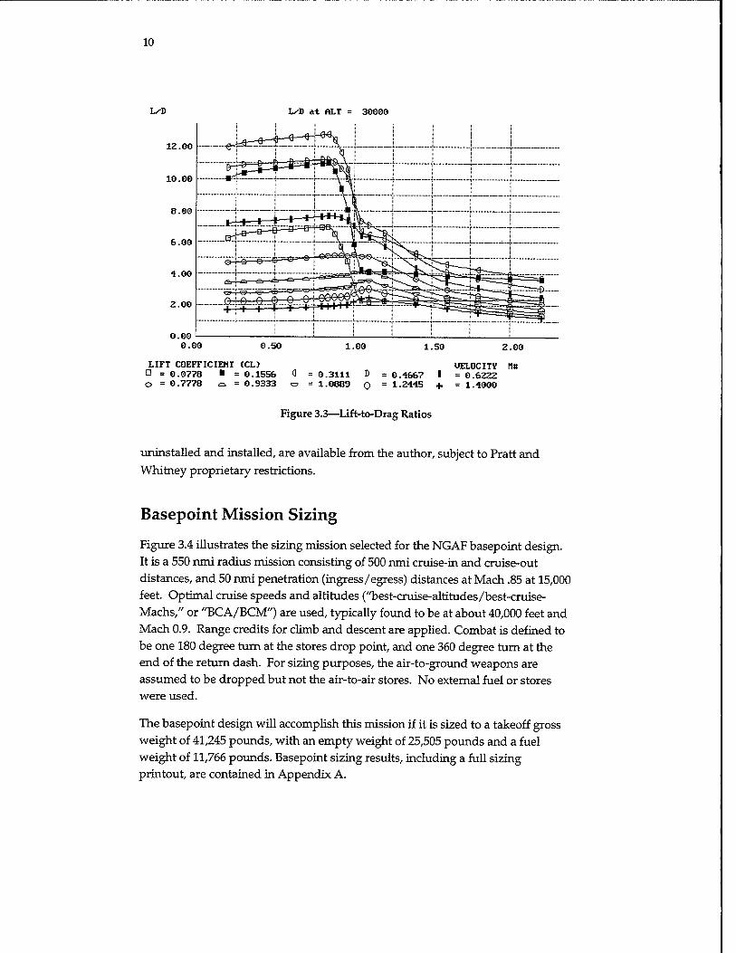
Aerodynamics estimates were made based on classical methods using the RDS- Professional computer program. Methods, assumptions, and results are detailed in Appendix A, and are summarized in Figure 3.3 as lift-to-drag ratio at various speeds and altitudes. Cruise lift-to-drag ratio is about 11 to 12, depending on speed, weight, and altitude. These results track well with advanced fighter results obtained by contractor and government organizations.
Weights were estimated statistically using equations developed by Vought Aircraft (Raymer, 1989), with adjustments for composite material usage based on recent experience and future projections. Key weight assumptions for the basepoint analysis are provided in Appendix A, which were extensively reviewed with staff at Naval Air Systems Command, Air Force Wright Aeronautical Labs, and the Naval Air Warfare Center. Weight results for the basepoint design are given in Table 3.2 and correlate well with contractor and government laboratories' estimates for similar designs.
Table 3.3 shows the weight savings obtained in this analysis from the use of composites. This shows what the weights would have been had traditional metal structure been used, compared to the component weights used for the basepoint design, which assumed substantial usage of advanced composite structure especially in the wing and tail skins.
A single 1990s-technology, large-core fighter engine was used for the study. Data were provided by Pratt and Whitney Aircraft from their parametric cycle deck. Classical installation analysis was performed. Engine data, both
10
LxD
12.00
10.00
8.00
6.00
4.00
2.00
0.00 0.00
L/D at ALT 30000
0.50 1.00 1.50 2.00
LIFT COEFFICIENT (CD Ö = 0.0778 ■ = 0.1556 0 = 0.3111 D O = 0.7778 ö = 0.9333 c = 1.0889 Q
UELOCITV H« = 0.4667 I = 0.6222 = 1.2445 + = 1.4000
Figure 3.3—Lift-to-Drag Ratios
uninstalled and installed, are available from the author, subject to Pratt and Whitney proprietary restrictions.
Basepoint Mission Sizing
Figure 3.4 illustrates the sizing mission selected for the NGAF basepoint design. It is a 550 nmi radius mission consisting of 500 nmi cruise-in and cruise-out distances, and 50 nmi penetration (ingress/egress) distances at Mach .85 at 15,000 feet. Optimal cruise speeds and altitudes ("best-cruise-altitudes/best-cruise- Machs," or "BCA/BCM") are used, typically found to be at about 40,000 feet and Mach 0.9. Range credits for climb and descent are applied. Combat is defined to be one 180 degree turn at the stores drop point, and one 360 degree turn at the end of the return dash. For sizing purposes, the air-to-ground weapons are assumed to be dropped but not the air-to-air stores. No external fuel or stores were used.
The basepoint design will accomplish this mission if it is sized to a takeoff gross weight of 41,245 pounds, with an empty weight of 25,505 pounds and a fuel weight of 11,766 pounds. Basepoint sizing results, including a full sizing printout, are contained in Appendix A.

11
Table 3.2
Basepoint Weights Results (Weights in Pounds)
Fighter/Attack Group Weight Statement: File NGAF2.DWT
Structures Group 11267.0 Wing 4088.5 Horizontal tail 0.0 Vertical tail 789.4 Fuselage 4748.8 Main landing gear 775.1 Nose landing gear 318.1 Engine mounts 62.3 Firewall 113.0 Engine section 48.9 Air induction 322.9
Propulsion Group 6393.8 Engine(s) 4930.0 Tailpipe 0.0 Engine cooling 273.0 Oil cooling 37.8 Engine controls 21.2 Starter 72.9 Fuel system 1058.9
Equipment Group 4924.7 Flight controls 1020.8 Instruments 128.8 Hydraulics 171.7 Electrical 706.5 Avionics 1945.4 Furnishings 391.7 Air conditioning 536.0 Handling gear 23.8 Miscellaneous empty weight 2920.0 Total weight empty 25505.5
Useful Load Group 15739.5 Crew 220.0 Fuel 11765.5 Oil 50.0 Cargo 2860.0 Passengers 0.0 Miscellaneous useful load 844.0
Design gross weight 41245.0
A number of commonly performed sizing sensitivity trade studies are provided in Appendix B to illustrate the sensitivity of this basepoint design to parametric changes in key sizing input parameters.1 These include variations in parasitic
1 "Sizing" refers to the calculation of the aircraft takeoff gross weight and fuel weight to perform some given mission. The physical size of the aircraft, including its length, wing area, structure, landing gear, and almost everything else, is considered a variable. One can think of an aircraft design that is drawn on a sheet of rubber drafting paper, allowing the design to be stretched to any size

12
Table 3.3
Weight Savings Through Use of Composite Materials
Traditional Metal
9.1% of weight structure 4.2% of weight empty
Basepoint Composites
Structures Group 12394.7 11267.0 Wing 4810.0 4088.5 Vertical tail 928.7 789.4 Fuselage 4998.7 4748.8 Main landing gear 775.1 775.1 Nose landing gear 318.1 318.1 Engine mounts 62.3 62.3 Firewall 113.0 113.0 Engine section 48.9 48.9 Air induction 339.9 322.9
Total Savings 1127.7 pounds
500 nm BCA/BCM
MIDMISSION: DROP A-G STORES
ONE 180 deg TURN
500 nm BCA/BCM
i 50 nm 50 nm M.85 at 15,000 ft
(530 KTS)
TAKEOFF: 4.6 min
20 MIN LOITER
LANDING
FULL INTERNAL STORES -2-JDAM (1000-POUND) -2-AIM-120
-M-61 GUN+500 mds
NO EXTERNAL FUEL OR STORES
Figure 3.4—RAND NGAF Sizing Mission
required. The process begins at the "as-drawn" takeoff gross weight, determined from initial estimations before the aircraft is drawn. At this as-drawn weight, the weights of all aircraft components, such as wing, fuselage, and landing gear, are calculated. After taking into account the weight of payload, crew, avionics, and other items, this leaves a certain amount of the as-drawn takeoff gross weight left over for fuel. Using engine characteristics and aerodynamic data, the aircraft's range over the selected sizing mission can be calculated. If the aircraft is unable to make the full desired range, it is then "sized upwards," or physically stretched to a larger size and a greater weight including a larger wing, tails, fuselage, landing gear, etc. At the larger size, the component weights are recalculated taking into account the higher loads, then the available fuel is recomputed and the mission performance is recalculated. This process iterates until it converges at an aircraft size, or takeoff gross weight, at which the available fuel allows the aircraft to perform the design mission. The expression "resized" refers to repeating this process of scaling a "rubber" aircraft upwards in size until it meets the mission, taking into account any changes such as a different payload, an alternative engine, or a new technology.

13
drag, drag due to lift, specific fuel consumption, dead weight (i.e., change in
unsized empty weight), payload weight, and limit load factor. These charts can be used for rapid estimation of the effect of various changes in design
requirements and assumptions.
Range Analysis with Overload Internal Fuel
In performing sizing and range analysis, fuel ground rules require that the
aircraft structure and performance calculations be done at the combat fuel
weight, which typically includes 50 to 60 percent of total internal fuel. Sizing
primary structure to this requirement, even including the use of advanced
composites, makes it very difficult to attain a fighter fuel fraction much over 25-
30 percent, which limits the available range.
To avoid an excessively large aircraft, it is usual for sizing purposes to define a
"design mission" that has less than the desired maximum range. The aircraft is
"sized" to attain this design range without use of external fuel (and typically
carrying a nominal combat payload rather than the maximum possible payload).
In other words, a calculation is made of the design takeoff gross weight, fuel
weight, and empty weight required to attain this design mission range. When
the aircraft is at the location of combat during the design mission, the aircraft's
weight must be such that the required maneuvering performance and structural
load factor are attained.
In service, though, aircraft are often flown at an overload weight through the use
of external fuel tanks. These can increase fuel up to perhaps a 40 percent fuel
fraction, with very little increase in empty weight. Takeoff weight is allowed to
increase substantially beyond the "design takeoff gross weight" to a "maximum
takeoff weight." Pylon attachment structure, landing gear, brakes, and other
affected components are deliberately overdesigned with this in mind.
When at the combat point (usually midmission for design purposes) starting
from such an overloaded takeoff weight, the aircraft is heavier than when it is at
the same combat point for the design mission, and so has reduced performance
and load factor allowance. This is standard practice for current fighters and
provides an affordable compromise between maneuvering performance and
maximum operating range.
When designing a stealth aircraft, one cannot rely on external fuel for long-range
missions. However, if one attempts to attain the desired maximum range by
increasing the internal fuel, traditional design practice and specifications say one
must design for maneuvering performance and allowable load factor at 50 or 60

14
percent of all internal fuel, including that extra fuel. This adds structural weight and increases the required wing area (and possibly thrust). As a result, the entire aircraft sizes up substantially in weight and cost.
As an alternative, one can provide additional internal fuel volume in the design concept but specify that the weight of such additional fuel will not be included in calculating design mission maneuvering performance and allowable load factors. For shorter-range missions during which high maneuvering is expected, the aircraft would take off without all tanks fully filled.
Note that stealth-designed aircraft typically have fuselage shaping and wing geometries that tend to provide extra fuel volume more readily than a traditional design. This shaping is a part of the "stealth penalty" that must be paid, but it permits internal overload fuel more readily than would be possible for, say, an
F-16-like design.
Provision for this additional "internal-external fuel" volume is analogous to the traditional use of external tanks. To determine the benefit of such an approach, a trade study was conducted by adding an assumed 1,000 gallons (6800 pounds) of additional fuel volume, without resizing the wing or increasing structural weight as would be required to meet maneuvering requirements with this extra fuel weight included. Instead, a nominal increment of 200 pounds was added to aircraft empty weight to allow for sealing, fuel lines, pumps, and additional fuel controls. Fuel fraction increased to about 40 percent of takeoff weight from the 30 percent of the basepoint, and aircraft takeoff gross weight increased to 48,119 pounds from the basepoint value of 41,245 pounds. Calculation of mission range indicated an increased mission radius from 550 nmi to 994 nmi. However, at this weight the structural load factor would reduce from 7.33 to about 6.5, and maneuvering performance would be reduced.
By way of comparison, a weight calculation showed that if the aircraft structure were to be resized to maintain the 7.33 load factor at a design takeoff gross weight of 48,119 pounds, the empty weight would have to increase to 28,260 pounds instead of the 25,706 pounds of this approach. This would eliminate half of the additional fuel weight we had sought.
Basepoint Performance Analysis
Performance analysis of the basepoint NGAF notional design concept was done using RDS-Professional, which uses standard classical aircraft analysis equations as detailed in Raymer (1989). Analyses were run at two midmission weights, one for the design mission and one for the overload mission using "internal-external"

15
fuel as described above. Midmission weight was defined as 50 percent of takeoff
fuel weight, air-to-air stores retained, and air-to-ground stores dropped.
Table 3.4 lists the design performance goal values and the calculated
performance for the basepoint design, calculated at mid-mission weights for both
the design mission and overload mission.
Figures in Appendix C detail the calculated aircraft performance including flight
envelope, cruise performance (range optimization), rate of climb, and turn
capabilities. Note that according to these results, there is adequate thrust from
the nonrefanned engine, and performance should not be considered to drive any
need for extensive upgrades to an existing advanced fighter engine.
Table 3.4
Performance Results
Design Goal Design Weight Overload Weight Design mission radius 550 nmi 550 nmi — Max radius 700+ nmi — 994 nmi Sustained turn at Mach 9 and 3.5 g 3.6 g 3.3 g at 30,000 ft
Instantaneous turn at 350 kt 20 deg/sec 22 deg/sec — and at 15,000 ft
Maximum speeds at 30,000 ft Mach 1.6 Mach 1.8 Mach 1.8 Accelerate 30 sec from Mach 27.5 sec 33.4 sec —
.8 to Mach 1.2 at 20,000 ft Takeoff 4,000 ft 2,114 ft 2,571 ft Landing 4,000 ft 3,994 ft 3,994 ft

16
4. Range/Payload/Design Trade Studies
Numerous trade studies were performed on this basepoint NGAF design concept, based on the analysis described above. These included range trades, payload trades, mission trades, technology trades, design trades, and others. Along with the sizing sensitivity curves provided in Appendix B, the charts and tables presented below can be used to quickly approximate additional trade studies not provided. Note that these were done on the basepoint design, which is land-based CTOL only. Effects of carrier and STOVL operations are discussed
in Section 5.
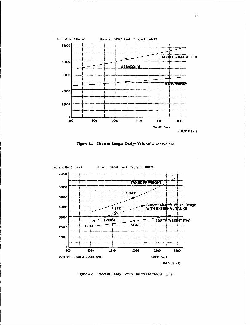
Basepoint Range Trades
The effect of design range requirement is shown in Figures 4.1 and 4.2. Figure 4.1 is based on use of design takeoff gross weight, and Figure 4.2 assumes use of additional "internal-external" fuel volume as described above. The upper lines of the graphs represent sized takeoff gross weight, and the lower lines depict resized empty weight. Ranges are given as total range, i.e., twice the mission
radius.
For comparison purposes, several current aircraft (with external tanks) are indicated on Figure 4.2 showing their empty weight and range, and a generic trend line for current aircraft with external fuel tanks is also shown. The reduced empty weight of the NGAF for a given range compared to current fighters is largely a reflection of the weight savings of modern structural and propulsion technologies, and the improved aerodynamic design and reduced drag from internal carriage of the overload fuel on the NGAF.
Two other range studies considered changes in the mission. A supersonic dash study replaced the subsonic penetration at 15,000 feet, Mach .85, with the same 50 nmi distance but at Mach 1.4 at 30,000 feet. Results are quite negative, with a 40 percent reduction in range. This is not surprising since the aircraft was not designed with "supercruise" in mind. The drag is too high and the engine is too small for dry supercruise, so the aircraft needs afterburning for supersonic flight and the fuel usage increases dramatically. Design for supercruise would have entailed increased weight and cost penalties, however, and no mission need for
supercruise was expressed.
40000
30000
ZOOO0
10000
17
Uo and Ue (lbs-n) Uo g.s. RANGE (tin) Project: NGAF2
50000
600
Basepoint
800 1000
TAKEOFF GROSS WEIGHT
1200 1400 1600
RANGE (nn) (=RADIUS x 2
Figure 4.1—Effect of Range: Design Takeoff Gross Weight
Uo and Ue (lbs-n) Uo u.s. RANGE (nn) Project: NGAF2
70000
60000
50000
40000
30000
20000
10000
vs. Range TANKS
EMPTY WEIGrH(We)
500 1000
2-10001b JDAM S 2-AIM-120C
1500 2000 2500 3000
RANGE (nn)
(=RADIUSx2)
Figure 4.2—Effect of Range: With "Internal-External" Fuel

18
A ferry mission study was conducted using full overload fuel and no external tanks. AIM-120s were carried, but not JDAMs. The basepoint design attained a ferry range of 2320 nmi. Stair-step cruise-climb was permitted, with optimal altitudes ranging from 40,000 to 44,000 feet. Mach 0.9 was the optimal speed throughout cruise. A standard 20 minute loiter was used.
Basepoint Payload Trades
Payload trade studies were conducted on this basepoint design to determine the best size for the internal weapons bays (if they are required), and the resulting
mission ranges of various options including no internal bays, bays sized for 1,000 pound weapons, bays sized for 2,000 pound weapons, and various overload external carriage options. These are detailed in Appendix B, and summarized
below.
Figure 4.3 shows the basepoint weapon bays, which are 137 inches long, 26 inches wide, and 26 inches high. Each holds a single 1,000 pound JDAM, or MK-83, or Tactical Munitions Dispenser (TMD). Carriage of four MK-82s internally is also possible, but vertical overlap is required. This is undesirable because it complicates weapon loading and may prevent releasing all stores.
External carriage of an additional six 1,000 pound JDAMs (total of eight) is shown in Appendix B. Range calculations indicate a total of 396 nmi radius, a 28 percent reduction from the baseline. External carriage of four 2,000 pound JDAMs is also possible, with calculated range of 410 nmi, a 25 percent reduction from the baseline. Note that the internal bays are left empty in this case.
The 1,000 pound JDAM was selected for sizing the baseline internal weapons bay, but there are strong operations effectiveness arguments in favor of internal carriage of the 2,000 pound JDAM instead. Some analysis indicates that the larger JDAM is required for destruction of key targets, and the threat environment may require stealth so that external carriage is not an option.
Figure 4.4 shows a design trade study for increased-length internal weapons bays capable of carrying the 2,000 pound JDAM. This requires a bay stretch of about 42 inches, to a total of 179 inches. To accommodate this larger bay, a fuselage stretch of about three feet is required. The larger weapons bay, with bigger doors, heavier hinges and actuators, and other considerations, will add about 300 pounds to the empty weight, and the fuselage stretch will increase the fuselage weight by another 130 pounds. In total, the empty weight increases by about 430 pounds. When this effect, plus the drag increase of the fuselage stretch, plus the increase in payload weight are all accounted for, the sized takeoff gross

19
TWO INTERNAL BAYS DIMENSIONS:
137"x26"x26"EACH 3" KEEL BETWEEN BAYS SEPARATE BAYS FOR
TWO AIM-120S
lOT
2-1,000-pound JDAMS
<S
<_ a 2-MK83S 2-TMDs
Figure 4.3—Basepoint Weapons Bay: JDAM, MK-83, and TMD
c >tre tehed Weapons Bay: 179 inch Length
-i
< : K
2-2,000-pound JDAM
. f CU -4-
1 \ \
2- GBU-2" T/B
Figure 4.4—Trade Study: Internal 2,000 lb JDAM

20
weight increases 3 percent to 42,494 pounds. Alternatively, at an unchanged takeoff weight, the range decreases 6 percent due to the reduction in available
fuel weight.
Note in Figure 4.4 that this stretched, 179 inch bay also permits internal carriage of the GBU-27/B. Unfortunately, it will not permit an increase over the basepoint bay in the number of MK-82s or TMDs . That would require even more stretch of the bay and fuselage and is probably not feasible in an NGAF- sized aircraft. Also, for the STOVL option described later, the longer bay, added to the extra length for the STOVL equipment, may drive the aircraft to an
excessive total length.
This stretched bay also permits internal carriage of four more AIM-120s (assuming that there is sufficient room for the required retracting trapeze launchers required), whereas the basepoint bay is only long enough for the AIM-9 air-to-air missile. This increased stealthy air-to-air capability may provide sufficient motivation for the Air Force to request the longer bay. Actually, a bay stretch to only about 168 inches would permit the four more AIM-120s, with a reduced penalty compared to the bay sized for the internal 2,000 pound JDAMs.
Another payload trade study considered the alternative of not using an internal bay. This would obviously hinder attainment of a substantial level of stealth. If a new external-store stealth technology emerges, or stealth is de-emphasized, elimination of the bay can save about five feet of fuselage length and 1500 pounds of empty weight, providing a great increase in fuel weight available at a given design takeoff gross weight. Another benefit is an increase in payload flexibility versus internal weapons carriage. In addition to stealth problems, supersonic performance would suffer.
Despite the weight of the external pylons, and the drag of external stores and pylons, the net effect is a 20 percent increase in range compared to the basepoint with internal bays, operating at design takeoff gross weight. However, if two 610 gallon tanks are added to the no-bay version, and it is compared to the "internal- external fuel" overloaded basepoint, the range increase drops to only about 5
percent.
Yet another payload option under discussion is the elimination of a permanent gun installation for an advanced fighter. Combat is expected to be decided with beyond-visual-range (BVR) missiles, and even short-range missiles are considered by some to be essentially for "back-up" purposes. On the other hand, the history of aircraft such as the F-4, which was developed without a gun in the expectation that new missiles would make guns unnecessary, should be considered. Later combat experiences forced the inefficient retrofit of a gun.
21
Pilots in combat tend to not want to shoot the last missile if there is no gun. Also, a gun may be required for cheap, soft target attack and for strafing in low-threat scenarios.
The NGAF basepoint has a 20 mm M-61 gun with 500 rounds of ammunition. This totals 844 pounds of dead weight, plus about 300 pounds for installation. To assess the savings associated with elimination of the gun, a range trade was conducted by eliminating the gun and substituting fuel instead. This produces a radius increase of about 90 nmi (16 percent).
An alternative would be to build the aircraft without a gun, but with attachments for a carefully designed podded gun arrangement. If done properly, this would impose almost no weight penalty when the gun was not being carried, so that the weight savings and range increase described above would be attained when the pod was not installed. However, when the pod was installed, there would be an additional weight and drag penalty so that the podded-gun configuration would have greater weight and less range than an aircraft in which the gun was permanently installed.
Payload trade studies are summarized in Table 4.1. Note that these all assume the same design takeoff gross weight, and that best cruise speeds and altitudes are found for each one.
Design Trades
Several design and technology trade studies were conducted using this NGAF land-based basepoint and are described in the following subsections. Many more such studies can be developed by using the design sensitivities trades detailed in Appendix A.
An important design trade study considered the provision of space for a second seat for training aircraft and possibly for a weapons/systems operator. Although it is generally possible to stretch a single-seat aircraft to provide room for a second seat, this is quite expensive. It is preferable to design the aircraft with an exiting but unused hole sized for a second seat, like the F-15. This volume can also later be used for additional avionics or possibly fuel for a growth version of the aircraft.
To determine the penalty of provision of such extra volume, a trade study was conducted. The fuselage was stretched by three feet which, with proper repackaging, should allow for a hole for a second seat. This added about 330 pounds empty weight (not including a second seat or cockpit). There was also a

22
Table 4.1
Payload Trade Studies
Design Mission Percent Option Radius (nmi) Change
Two 1,000 lb JDAM (internal baseline) 550 n/a
Eight 1,000 lb JDAM (6 external) 396 -28 Four 2,000 lb JDAM (external) 410 -25 Two 2,000 lb JDAM (internal-
stretched fuselage) 517 -6 Two 1,000 lb JDAM (external-
no bay) 660 +20 No gun (two 1,000 lb JDAM
internal) 640 +16
slight drag increase. The result of this was a 2 percent increase in sized takeoff weight, or a 6 percent decrease in range. This small up-front penalty is probably less than the cost penalty of a later program to stretch the aircraft for a second seat. As discussed later, it would also be possible for this stretch for a second seat to provide the volume required for STOVL lift gear.
Technology Trades
The technology level incorporated in the basepoint design of this study includes essentially well-matured, currently available advanced technologies, as typified by the technology level of the F-22. Results of this study indicate that those technologies provide an acceptable answer, so that no technology development and maturation is required for development of a tri-service NGAF. However, it is always desirable to incorporate newer technologies if the cost and risk are acceptable and a better, cheaper aircraft results.
Two studies to determine potential payoffs from advanced technology use were made. These technologies were selected as being close enough to maturation that, with suitable investment, they could probably be ready in time for full-scale engineering development of an NGAF beginning early in the next century. However, neither is now mature enough to warrant inclusion on the basepoint. The selected technologies, both being studied by NASA, are the "tailless" and "laminar flow control" technologies.
The "tailless" technology is a design approach in which both horizontal and vertical tails are completely eliminated. This saves on weight, drag, and signature, but brings about severe problems in stability and control. The emerging technology approach is to use high-speed thrust vectoring nozzles to

23
provide pitch and yaw control. A key question, though, is whether the weight and complexity penalties associated with these nozzles and other control devices that may be required will outweigh the weight and drag savings of removing the tails.
Recent X-31 flight tests have validated at least a portion of this approach. The flight control system was programmed so that the rudder exactly counterbalanced the normal effect of the vertical tail, so that the aircraft's aerodynamic stability was as if the tail were removed. Then, the vectored nozzle was programmed to restore the required stability and control. Test results were quite favorable. However, the key question of providing control during reduced power operation or while recovering from a flame-out remains unanswered. Options for controlling the aircraft include Harrier-like reaction control jets, forebody vortex control devices, pop-out aerodynamics surfaces, and others. All would add weight and complexity to the design.
To assess the potential of the tailless design technology, the optimistic "best case" was analyzed in which there is no weight or volume effect from the attainment of acceptable stability and control (this optimistically assumes that the weight penalties already in the basepoint design for 2-D vectoring nozzles are sufficient to provide the missing pitch and yaw control). The basepoint aircraft was analyzed with its tails removed as shown in Figure 4.5, and with no further penalty in terms of weight or volume. This reduced the empty weight of the aircraft by 789 pounds and reduced drag as well, producing an 8 percent reduction in sized takeoff weight, or a 24 percent increase in range. The real- world result will be less, after the problems described above are solved, but this result seems to indicate that this technology is worthy of study.
Figure 4.5—Tailless Trade Study

24
A similar trade study was performed for the application of active laminar flow control. This technology is in flight test on the F-16XL, with promising results. To perform the trade study, a 50 percent attainment of laminar flow was assumed for cruise. This is substantially better than the 10 percent laminar flow used for the basepoint analysis, which is already better than the typical existing fighter, which attains virtually no laminar flow. Attainment of 10 percent is based on better design using computational fluid dynamics to control pressure gradients and improved manufacturing methods and paints to obtain a smoother surface.
Attainment of 50 percent laminar flow will require these methods plus localized use of suction, using skill panels with very tiny holes and appropriate ducting to some sort of an air pump. This imposes a weight, volume, complexity, maintenance, and cost penalty. To scope the potential benefit, the trade study was conducted assuming no such penalties. Drag was simply recalculated using the 50 percent assumption.
The resulting lift-to-drag ratios are shown in Figure 4.6 and can be compared to Figure 3.3 for the basepoint analysis. At a typical cruise condition this provides a lift-to-drag ratio of over 14, which is a 10 percent reduction in overall drag, and yields a 7 percent reduction in sized takeoff weight, or a 22 percent increase in range. As with the tailless trade, the real-world result will be less, but this technology also seems worthy of further study.
Engine Trades
It is common in early conceptual design of a new aircraft to perform "rubber engine" trade studies, in which it is assumed that a new engine can be built to any size and thrust required. This was a good assumption in the past, when a new fighter would be designed around a new engine (for example, the F-22 and F-119 engines). For the foreseeable future, though, a new fighter program will almost certainly be forced by cost constraints into using an existing or derivative engine.
However, "rubber engine" trade studies can provide a useful indication as to whether selected existing/derivative engines are in approximately the correct thrust class. Figure 4.7 shows the results of such a study, indicating the design sensitivity to changes in thrust-to-weight ratio and wing loading. Performance constraint curves are shown, indicating that the basepoint engine is actually a fairly good match to the requirements and in fact may have a slight excess of thrust based on this analysis. This can be seen from the fact that the baseline engine size, represented by the star on the carpet plot, is actually on one of the

L/D
0.00 0.00
L/D at ALT (ft)= 30000 :ngaf2
0.50 1.00 1.50 2.00
LIFT COEFFICIENT (CD Macht» 0 = 0.0778 ■ = 0.1556 0 = 0.3111 D = 0.4667 I = 0.6222 O = 0.7778 o = 0.9333 o = 1.0889 0 = 1-2445 + = 1.4000
Figure 4.6—Lift-to-Drag Ratios with Laminar Flow Technology
25
Uo (lbs-n)
46000
44000
42000
40000
38000
36000
34000
Unsealed Basepoint
Engine
NGAF2 CARPET PLOT: U/S us T/U
.55.93
62.92 69.91
32000
ALL EXCEED: 1-Takeoff 4-InstTurn 5-Ps3n=3
PERFORMANCE CONSTRAINT CURUES: D 2-Landing ■ 3-Accel Q 6-Psen=3
76.90 83.89
939
0.861
0.783
T/W 0.704
0.626
Figure 4.7—Parametric Design Optimization

26
performance constraint lines and is slightly above the other two that appear on the carpet plot.
As mentioned, the basepoint design concept uses a 1990s-technology large-core fighter engine comparable in size and cycle to the engines used in today's advanced fighters (simulated from unclassified sources), with low-cost, preplanned product improvement upgrades to produce a modest increase in thrust by early in the next century. Results seem to indicate that, for the land- based basepoint, such an engine is more than adequate.
More aggressive modifications to an existing engine, including a new and larger fan, could produce an engine with greater cruise efficiency. Data for such a notional derivative engine were provided by Pratt and Whitney and are available
from the author subject to proprietary restrictions. Installation of this advanced derivative engine produced a 12 percent increase in maximum radius when the "internal-external" overload fuel is used and a 17 percent increase in radius at design weight. This increase, while highly desirable, must be balanced against the increase in development cost.
On the other hand, any of the concepts for attaining a STOVL version of an NGAF will require substantial engine development costs, in some combination of main engine development and/or lift equipment development (lift engine/fan, nozzles, and other hardware). It may prove wise to spend the majority of the engine development cost on the hardware that will be used by all versions, not just the STOVL variant. But this must be balanced against the technical merits of the STOVL hardware alternatives and the total risk of development.
Another consideration that may in fact drive selection of a refanned engine is the improvement in infrared (IR) signature that would occur. Detailed survivability analysis is required to fully assess this benefit versus the cost penalty for this improvement.
Design Trades Summary
Several observations can be summarized from the above design trade studies. First, the initially selected set of design requirements seems to be a fairly reasonable point of departure. An acceptable basepoint aircraft can be constructed around them, and parametric excursions about them do not reveal any obviously superior alternative set of requirements. The nominal 550 nmi design mission range produces a reasonable empty weight, and use of overload "internal-external" fuel allows for extended range missions.

27
The 1,000 pound JDAM seems desirable as the nominal weapon for high-threat environments (i.e., carried internally), but the range reduction or weight increase to go to the 2,000 pound JDAM is not too excessive. This could change when STOVL is considered because of the effect on fuselage length. The final selection must be made from in-depth lethality assessments, which are beyond the scope of this study. A capability for external carriage of up to four 2,000 pound weapons is desirable and readily feasible.
The technology suite of the basepoint design, a rather conservative improvement over F-22 technology levels, produces a good design at a low risk. However, the two emerging technologies studied (tailless and active laminar flow) both appear to offer substantial benefits. It is premature to suggest either for inclusion in a baseline design, but technology maturation efforts should continue with an eye toward incorporation of one or both technologies when they are proven.
Finally, a near-term engine comparable in size and cycle to the engines used in today's advanced fighters seems to be more than adequate. A cost and risk minimization strategy would be to specify some existing production engine for an NGAF design, with only those minimal modifications driven by integration issues (such as the nozzle external geometry). Selection of a highly modified engine (such as refanned) or an alternative engine not currently (or nearly) in production should be done only after a detailed cost-effectiveness comparison, with all engine development costs "charged" against the benefits received. The RAND analysis does not support the notion that "we must refan anyway, so the incremental cost doesn't count," unless it is determined that survivability requirements force refanning of the engine to reduce the IR signature.

28
5. Joint-Service Options Study
Overview
One of the most important areas of this research effort has dealt with the options for providing a useful military capability for all three services through a joint and largely common program. Because of the cost constraints of the current military environment, this is critical for obtaining the political base for funding of any
program.
For a tri-service NGAF, the design must be able to operate from traditional runways and aircraft carriers, yet have STOVL capability for operation from extremely short strips. At the same time, it must also provide good range and payload. It is not required that the same actual aircraft do all three. We can postulate production line variants that are individually tailored to each of these. However, history tells us that what are originally intended to be fairly minor production line variants can rapidly become highly uncommon designs, with great effect on the cost savings expected from commonality.
The history of the F-111B is well known, with joint-service development falling apart because of the inability of a single aircraft to fulfill both Navy and Air Force needs. In the end, the Air Force took the F-lll, and the Navy started over again and developed the F-14. More recently, the Navy version of the F-22, the NATF, was to have been developed. Again, diverging requirements prevented the type of commonality that would have offered cost savings, and the program was ultimately canceled. However, the attempt to reach some measure of commonality acted as a constraint on the design of both ATF and NATF, with a negative effect on weight and cost of both designs.
It is true that airframe commonality is not the whole story. Airframe costs are less than half the total costs, and airframe structure costs are only a portion of those. Avionics, engines, and other systems provide the majority of total costs, and even radically different airframe designs could be developed with commonality in those areas. This is certainly desirable. However, a noncommon airframe implies a duplication of design, development, testing, tooling, manufacturing, spares, logistics, and maintenance that should not be overlooked or trivialized. The greatest total cost savings will occur with the greatest amount
of commonality, including airframe structure.

29
The question is, can we obtain a highly common design that meets all three
services' crucial needs? What technical strategy maximizes this? Or, what
measured amount of noncommon design features are necessary to meet crucial
needs? And, most important, how should design-to requirements be established
to attain a low-risk/high-payoff approach without unnecessarily tying the
designers' hands?
A key issue is commonality versus modularity (they are in opposition: A 100
percent common design needs no modularity). The limiting factor in the
attainment of commonality is the effect of the substantial design constraints and
penalties imposed by either conventional carrier operation (catapult and
arresting gear) or STOVL. Three options exist for meeting tri-service needs. We
could develop a single design with no modularity, compromising on
requirements as needed. However, this approach undoubtedly offers the poorest
range/payload performance because the carrier and/or STOVL penalties are left
in all planes, and this is not recommended (see O'Neil, 1994, for further
discussion).
A second option would be a "two-way" modularity design, with a basic design
and a pre-planned derivative. Since it is easier to remove conventional carrier-
capability or STOVL than it is to add them, this basic design would contain one
or the other, and the derivative would, as much as possible, remove them. If
Marine STOVL needs are to be met with this design, the basic design would have
to be STOVL, and it would use STOVL rather than conventional catapult and
arresting gear for operating off carriers.
Finally, a true "three-way" modularity design could be produced which is
produced in land-based, conventional carrier-based, and STOVL variants. This
probably offers maximum performance, but at the highest cost because of the
substantial reduction in commonality.
Our research included a comparative trade study of "two-way" modularity
approaches, in which a single basic design incorporates some production-line
variations yielding two alternative versions. This was followed by a study of a
"three-way" modularity approach. The purpose of this research was to identify a
preferred approach by estimating the aircraft design penalties associated with
conventional and STOVL carrier operation and to assess the residual weight and
performance penalties imposed on an Air Force derivative aircraft from these
approaches.

30
Two-Way Modularity Study
The comparison of several "two-way" modularity approaches followed the
methodology shown in Figure 5.1. Two alternative families of related configurations were developed from the land-CTOL-only initial basepoint
configuration described above and detailed in Appendix A. In both cases, a carrier-capable aircraft would be designed and produced, and an Air Force derivative would be produced on the same production line. In one case (upper half of Figure 5.1), the traditional catapult and arresting gear are used for CV capability, whereas in the other case (lower half of Figure 5.1), the carrier capability is provided using STOVL. Both of these approaches offer the
possibility of a highly common airframe.
Note that the two designs in the middle of Figure 5.1 are derived from the land-
CTOL basepoint design in the design sense of the word (similar arrangement and features) but are not in any way production-line derivatives of that design. Those two designs are alternatives for a basic production aircraft with carrier capabilities. The two designs at the right of Figure 5.1 are each production-line derivatives of the carrier-based design to its immediate left.
The first two-way modularity approach, shown at the top of Figure 5.1, represents a joint Air Force-Navy aircraft using conventional catapult and arresting hook for CV operation. It has a highly common basic design with certain readily removable items that are replaced or eliminated on the Air Force version. For this research, a carrier-suitable CTOL aircraft ("CV-CTOL") was
CV-CTOL AF-DERIV
NAVY
USMC & NAVY
LAND-BASED DERIVATIVES
FOR AIR FORCE
NO-COMMONALITY CTOL BASEPOINT: POINT OFDEPARTURE
CV-STOVL deSTOVL
Figure 5.1—Joint-Service Design Study Methodology
31
developed from the initial land-CTOL basepoint described earlier. This was done by providing a heavier landing gear, hook, and catapult gear, including a wing fold, and incorporating the internal structural enhancements associated with carrier operation.
An Air Force land-based derivative ("AF-Deriv") of this CV-capable design was then defined by removing catapult gear, reducing the hook and landing gear to land-based aircraft needs, and eliminating the wing fold (saving a portion of the weight penalty). Primary structure was assumed unchanged to maximize commonality.
This CV-CTOL plus AF-derivative approach requires that Marine Corps STOVL aviation needs be met with some other aircraft (such as a super-Harrier upgrade). For a full assessment of this option, the costs of separately meeting Marine Corps needs should be considered (this approach, however, is not the one recommended).
The second joint-service design approach, shown at the bottom of Figure 5.1, uses a STOVL design for both Navy and Marine Corps needs ("CV-STOVL"). For the Air Force, a "de-STOVL" derivative with STOVL equipment removed would be produced.
Note that this approach does not necessarily imply that the Navy stop using large-deck carriers. As will be shown, the desired range-payload is best attained through the use of the catapult plus the STOVL equipment.
For study purposes, the lift-plus-lift-cruise STOVL technology was selected. In addition to being one of only two operationally proven STOVL approaches, this is similar enough to remote-fan lift concepts in design layout and weight penalty that the results should be generically applicable to them as well. Note that this selection for study purposes was made before the contractors settled on their preferred concepts.
The basepoint design was stretched by three feet to make room for the lift engine, and a pair of retracting Harrier-like nozzles were added between the core and afterburner of the main engine.
For the CTOL derivative ("de-STOVL"), the lift engine, extra nozzles, and wing fold were removed. It was assumed that the fuselage stretch would be retained and used for growth capacity for fuel and avionics. Another good use for this space would be for a second seat for trainer and special-purpose aircraft.
Next, these two alternative approaches for two-way modularity (CV-CTOL plus AF-Deriv, or CV-STOVL plus de-STOVL) were analyzed using a consistent set of

32
assumptions and ground rules. This analysis follows the methods described earlier for the basepoint concept.
Two-Way Study Analysis Assumptions
The analysis factors and assumptions for this comparative study are outlined in Table 5.1 (basepoint factors and assumptions are repeated for comparison purposes). These were extensively reviewed with personnel at Naval Air Systems Command, Air Force Wright Aeronautical Labs, and the Naval Air Warfare Center. Be advised that the numbers in this table almost completely drive the results that follow below, and if the results are questioned, assumptions in this table are likely to be the reason.
Design of an aircraft able to operate from an aircraft carrier using the catapult and arresting gear imposes substantial penalties. The greatest is in increased weight, especially for the airframe structural enhancements for the extra loads
Table 5.1
CTOL/Carrier/STOVL Factors and Assumptions
Base CV-CTOL AF-Deriv CV-STOVL De-STOVL Reserve and trapped (%) 6 6 6 6 6 Landing loiter (min) 20 20 20 10 + 30s
hover 20
Weights Tailhook (lb) 120 180 120 120 120 Catapult gear (lb) — — — — — Landing load factor3 6 9 6 6 6 Landing gear adjust^ — 1.5 1.2 1.2 1.1 Removable STOVL
weight — — — 2000 — Nonremovable STOVL
weight — — — 250 250 Wing composite adjust .85 .85 .85 .85 .85 Wing-fold penalty — 1.08 1.04 1.08 1.04 Wing carrier structure
penalty — 1.02 1.02 — — Net wing adjust factor .85 .94 .90 .92 .88 Fuselage composite
adjustment .95 .95 .95 .95 .95 Fuselage carrier penalty- — 1.10 1.10 — — Net fuselage adjustment
factor .95 1.05 1.05 .95 .95 Tail composite adjustment .85 .85 .85 .85 .85
aUltimate = 1.5 x landing gear limit load factor. ''Adjustments calculated gear weight based on F-18L to F/A-18.
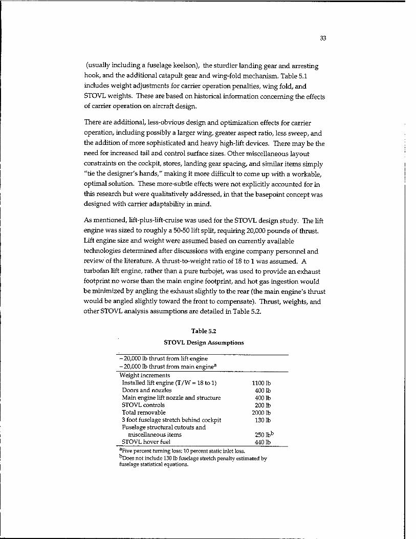
33
(usually including a fuselage keelson), the sturdier landing gear and arresting hook, and the additional catapult gear and wing-fold mechanism. Table 5.1 includes weight adjustments for carrier operation penalties, wing fold, and STOVL weights. These are based on historical information concerning the effects of carrier operation on aircraft design.
There are additional, less-obvious design and optimization effects for carrier operation, including possibly a larger wing, greater aspect ratio, less sweep, and the addition of more sophisticated and heavy high-lift devices. There may be the need for increased tail and control surface sizes. Other miscellaneous layout constraints on the cockpit, stores, landing gear spacing, and similar items simply "tie the designer's hands," making it more difficult to come up with a workable, optimal solution. These more-subtle effects were not explicitly accounted for in this research but were qualitatively addressed, in that the basepoint concept was designed with carrier adaptability in mind.
As mentioned, lift-plus-lift-cruise was used for the STOVL design study. The lift engine was sized to roughly a 50-50 lift split, requiring 20,000 pounds of thrust. Lift engine size and weight were assumed based on currently available technologies determined after discussions with engine company personnel and review of the literature. A thrust-to-weight ratio of 18 to 1 was assumed. A turbofan lift engine, rather than a pure turbojet, was used to provide an exhaust footprint no worse than the main engine footprint, and hot gas ingestion would be minimized by angling the exhaust slightly to the rear (the main engine's thrust would be angled slightly toward the front to compensate). Thrust, weights, and other STOVL analysis assumptions are detailed in Table 5.2.
Table 5.2
STOVL Design Assumptions
- 20,000 lb thrust from lift engine - 20,000 lb thrust from main engine3
Weight increments Installed lift engine (T/W = 18 to 1) 1100 lb Doors and nozzles 4001b Main engine lift nozzle and structure 4001b STOVL controls 2001b Total removable 2000 lb 3 foot fuselage stretch behind cockpit 1301b Fuselage structural cutouts and
miscellaneous items 250 lbb
STOVL hover fuel 4401b aFive percent turning loss; 10 percent static inlet loss. bDoes not include 130 lb fusel fuselage statistical equations. "Does not include 130 lb fuselage stretch penalty estimated by

34
Two-Way Study Results
Using these assumptions, the empty weights of the two design alternatives and their Air Force derivatives were analyzed to permit range calculations. Weight results are presented in standard group weight format in Appendix D and summarized in Figure 5.2. Empty weight for the conventional carrier-based option has increased by 7 percent and by almost 12 percent for the STOVL carrier-based design. The STOVL carrier-based option therefore has an empty weight about 5 percent higher than the equivalent conventional carrier-based
design.
The land-based derivatives of these options show a reverse trend. It is actually easier to "remove" empty weight penalty from a lift engine (or lift fan) STOVL
concept than from a conventional carrier-based design. The STOVL-derivative design has a 2.5 percent higher empty weight than the land-based basepoint, whereas the concept derived from the conventional carrier-based design has almost 4 percent higher empty weight.
Thus, it should be expected from these numbers that, although the Navy gets a slightly lighter aircraft from a conventional carrier-based design, the Air Force actually gets a lighter derivative aircraft if the Navy chooses to use STOVL to operate off the carriers (and this option gives the Marine Corps a STOVL
aircraft).
WEIGHT (LBS) 45000T ;
40000 I
35000 |
30000 |
25000 |
20000 |
15000)
looooi
5000-
■+- 4- AF BASE CV-CTOL CV DERIV STOVL DE-STOVL
□FUEL
BSTRUCTURE
■ STOVL WEIGHT
EJPROPULSION
■ HOOK/CAT GEAR
oEQUIPMENT
■APU
El WEAPON BAY
nSTEALTH
■CREW/OIL
D PAYLOAD & GUN
Figure 5.2—Weights Results Summary (Unsized)

35
This empty-weight analysis is based on years of historical experience with the
design of carrier-based aircraft for the U.S. Navy, and with the subsequent
development of land-based derivatives for the U.S. Air Force. Examples include
the F-4 and F-18 (land-based "L" version, which was never built). There have
been considerable discussion and research in the last few years about the use of
advanced design and manufacturing technologies to greatly reduce the residual
("scar") weight penalty of a land-based derivative of a carrier-based aircraft. If
feasible and affordable, such approaches may change these results; they are
discussed later.
The increase in empty weight due to carrier operation and/or STOVL equipment
results in a reduction of available fuel and therefore a reduction in range at that
weight. Table 5.3 summarizes the range (radius) obtained over the sizing
mission of Figure 3.4 for the calculated empty weights of the alternative concepts,
holding takeoff gross weight constant. The basepoint design, which attains 550
nmi, is shown for comparison. Because of the difference in empty-weight
penalties, the Navy gets a slightly greater range from a conventional carrier-
based design, whereas the Air Force gets greater range from a derivative of a
STOVL aircraft.
To obtain the desired 550 nmi at design takeoff gross weight, these alternative
designs must be resized, scaling up the entire aircraft until range is met.
Resulting resized takeoff gross and empty weights are provided in Table 5.4.
However, it would not be desirable to size the aircraft up much past the 41,245
pound basepoint design takeoff gross weight because the empty weight grows
substantially past 25,000 pounds, which has a strong cost effect.
Note also the additional penalty of using Navy engine ground rules, which
assume the miriimum-acceptable new engine rather than nominal (average) new
engine, and add an additional 5 percent fuel flow safety factor on top of the Air
Force requirement for an additional 5 percent over mission fuel. These ground
rules add roughly 5 percent to the sized takeoff gross weight, or, at the same
weight, reduce range by about 10 percent.
Table 5.3
Mission Results—Fixed Takeoff Gross Weight
@Wo = 41,245 lb and W/S = 70 Base CV-CTOL
Air Force Derivative STOVL De-STOVL
Empty weight (lb) Radius (nmi)
25,506 550
27,312 350 (395)a
26,499 467
28,441 284 (322)a
26,139 500
aUsing nominal engine as does the Air Force.
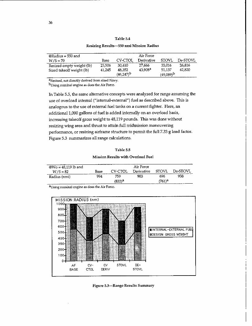
36
Table 5.4
Resizing Results—550 nmi Mission Radius
©Radius = 550 and W/S = 70
Air Force Base CV-CTOL Derivative STOVL De-STOVL
Resized empty weight (lb) Sized takeoff weight (lb)
25,506 30,410 27,666 33,016 26,816 41,245 48,352
(46,247)b 43,908a 51,137
(49,089)b 42,820
aResized, not directly derived from sized Navy. ''Using nominal engine as does the Air Force.
In Table 5.5, the same alternative concepts were analyzed for range assuming the
use of overload internal ("internal-external") fuel as described above. This is
analogous to the use of external fuel tanks on a current fighter. Here, an
additional 1,000 gallons of fuel is added internally on an overload basis,
increasing takeoff gross weight to 48,119 pounds. This was done without
resizing wing area and thrust to attain full midmission maneuvering
performance, or resizing airframe structure to permit the full 7.33 g load factor.
Figure 5.3 summarizes all range calculations.
Table 5.5
Mission Results with Overload Fuel
@Wo = 48,119 lb and W/S = 82 Base CV-CTOL
Air Force Derivative STOVL De-STOVL
Radius (nmi) 994 759 (832)a
903 696 (761)a
938
aUsing nominal engine as does the Air Force.
MISSION RADIUS (nm) 100!
■ INTERNAL-EXTERNAL FUElJ
BDESIGN GROSS WEIGHT
Figure 5.3—Range Results Summary

37
"These range results indicate that the conventional carrier-based approach has somewhat more maximum range than the STOVL option, whereas the Air Force derivatives show the reverse trend. However, all concepts can reach nearly 700 nmi of radius without refueling. Operations analysis studies indicate that this should be adequate for most expected missions.
"Soft-Cat" and "Ski-Jump" Carrier Operation
One possible problem concerns the ability of the STOVL concept to operate off the aircraft carrier at the overload weight of 48,119 pounds. This may be too heavy for a STOL takeoff in the few hundred feet of available runway length on the carrier. Two options exist to augment STOVL takeoff weight capabilities without adding the full catapult/arresting hook weight penalties.
One option discussed in O'Neil (1994) is the so-called "Soft-Cat," i.e., a soft catapult launch. This is illustrated in Figure 5.4. With this approach, the catapult is used but is programmed to a much softer stroke with an end speed of only, perhaps, 50-60 kt. Since loads go by the square of the end speed, loads are only about 15 to 25 percent of the normal catapult loads. Except for some minor local reinforcement, there should be virtually no weight penalty compared to the basepoint.
During this "soft-cat" launch, the STOVL lift engine (or fan) is turned on and vectored to the rear. At the same time, the main engine is at maximum afterburning thrust and is vectored down roughly 25 degrees to balance the front lift. This helps accelerate the aircraft during the launch and, once clear of the boat, augments the wing lift to support the aircraft as it accelerates to conventional flight speed (15 degrees angle of attack was assumed for calculations).
CATAPULT
LIFT ENGINE(or fan) VECTORED BACK -45 deg
-20,000 lbs THRUST
MAIN ENGINE IN MAX A.B. & VECTORED DOWN -25 deg
-32,000 lbs THRUST
Figure 5.4—"Soft-Cat" Launch Approach

38
Preliminary calculations for this lift-plus-lift-cruise concept indicate that the vertical component of thrust will total about 38,000 pounds, adding to the roughly 10,000 pounds of wing lift at 60 kt and 15 degrees angle of attack.
This "soft-cat" approach may depend on being able to use afterburning of the main engine while the front lift engine or fan is operating. This may be difficult for remote lift fan concepts because of the diversion of engine airflow or power and the extreme variation in nozzle exit area that may be imposed. These effects must be considered at a detailed level. Lift engine concepts should have no such difficulty. Also, the drag and pitching moment of the inlet for the lift engine or fan must be considered.
A second options, the "ski jump," is already in service in the United Kingdom for
the Sea Harrier. The ski jump is literally a takeoff area on the carrier that ends in a segment curved upwards by, typically, 5 to 15 degrees. The aircraft accelerates on the flat section and then hits the ski jump, which curves its trajectory upwards. When clear of the boat and ski jump, the aircraft is below flight speed at a heavy weight but is on an upwards ballistic trajectory, still accelerating. By the time it reaches the top of its ballistic arch, it has attained normal flying speed which, through the use of its STOVL equipment, is a fairly low speed of, perhaps,
50-60 kt.
The ski jump technology is well proven. Even non-STOVL aircraft such as the F-18 and F-14 have been tested off the Navy's ski jump test facility. Furthermore, a ski jump takeoff, unlike a "soft-cat," does not require any prelaunch hookup and so has advantages in aircraft launch rate. The problem with the ski jump is, of course, that the ramp itself must be added to the boats, and it is probable that the other aircraft on the carrier would not be able to use the launch areas configured with a ski jump. Whether this is a real problem operationally must be determined by other analysis.
For an operational STOVL aircraft, the use of a ski jump would add only minor beef-up weight in the landing gear areas (mostly the nose gear). In fact, there would be little penalty configuring a STOVL aircraft to be capable of using either soft-cat or ski jump, thus providing maximum flexibility.
This analysis indicates that, by selection of the STOVL option with use of "soft- cat" and/or ski jump, Navy and Air Force needs can be met by a highly common airframe. Marine Corps needs for short-range, in-theater STOVL operations can also be met, and the Marine Corps can use conventional takeoffs for longer- range, land-based missions. Use of a highly common airframe provides obvious and demonstrated savings in terms of development, production, and support cost.

39
Three-Way Modularity Study
If the above analysis proves naive or the design requirements become too diverse for such a highly common approach to work, one option is to use a "three-way modularity" approach in which some aircraft are built with STOVL equipment, some are built for catapult and arresting hook operation, and some are built only for conventional land-based operation.
The drawback of this approach is the residual or "scar" weight penalty associated with design for carrier-based operation. Use of catapult gear on the carrier imposes forward loads of two to five times the aircraft's weight, and the arrested landing imposes rearward loads of almost double the aircraft's weight. These loads require extensive redesign and strengthening of structure, as detailed in Table 5.1. Typically, a keelson structural arrangement must be used, and many structural members must be thickened.
Such structural overdesign is deeply embedded within the design, affecting virtually every part of the primary structure. When developing a non-carrier derivative for the Air Force, the extra design, test, and manufacturing efforts to remove these overstrength penalties have never to date proven worth the savings (although the Dassault Rafale, developed with extensive use of the computer- aided design and manufacturing system, is claimed to have reduced the residual scar weight to only 350 pounds without a huge cost effect).
If this scar weight penalty is added to residual STOVL penalties for all three versions of the aircraft, the combined effect penalizes all of the services' aircraft. A study of the magnitude of this effect was conducted, as shown in Figure 5.5. A common-core design was evolved from the basepoint described above, and three modular versions were developed—CV-CTOL for the Navy, Land CTOL for the Air Force, and STOVL for the Marine Corps. The common core includes the residual/nonremovable "scar" penalties for both CV-CTOL and STOVL as described above. Note that the same wings and tails were used for all three services, to keep as much commonality as possible. Analysis assumptions and adjustment factors are shown in Table 5.6 (which can be compared to the two- way modularity studies of Table 5.1).
Range and weight results are provided in Table 5.7. This approach, with reduced commonality compared to "two-way" modularity approaches outlined above, provides roughly 5 percent less range for the Navy and Air Force than would a traditional CV design plus land-based derivative. Compared to the CV-STOVL approach, the Navy version of the "three-way" modularity design gains about 4 percent in range, but its Air Force derivative has about 8 percent

40
Highly-Common Approach
CV-CTOL HEAVY GEAR CAT, HOOK
LAND CTOL
COMMON CORE -SCAR FOR CV
AND STOVL -STRETCHED
+2000 lbs STOVL
Figure 5.5— 'Three-Way" Modularity Study
Table 5.6
"Three-Way" Modularity Factors and Assumptions
Base USN-CV AF-Land USMC-STOVL Reserve and trapped
(%) 6 6 6 6 Landing loiter (min) 20 20 20 10 Weights Tailhook (lb) 120 180 120 120 Catapult gear (lb) — 50 — — Landing load factor3 6 9 6 6 Landing gear adjust*3 — 1.5 1.2 1.2 Removable STOVL
weight — — — 2000 Nonremovable
STOVL weight — 250 250 250 Wing composite
adjust 85 .85 .85 .85 Wing fold penalty — 1.08 1.04 1.08 Wing carrier
structure penalty — 1.02 1.02 1.02 Net wing adjust
factor .85 .94 .90 .94 Fuselage composite
adjustment .95 .95 .95 .95 Fuselage carrier
penalty — 1.10 1.10 1.10 Net fuselage
adjustment factor .95 1.05 1.05 1.05 Tail composite
adjustment .85 .85 .85 .85 NOTE: All factors get 3 foot fuselage stretch for STOVL (380 lb + drag). aUltimate = 1.5 x landing gear limit load factor. b Adjustments calculated gear weight based on F-18L to F/A-18.

41
less range compared to a derivative of a STOVL design. Also, there would probably be a higher total program cost as a result of reduced commonality.
Table 5.7
"Three-Way" Modularity Results
©Radius = 550 and (Wo = 41,245 lb)
USAF Base Carrier STOVL Land
Empty weight (lb) Radius (nmi) (Wo = 48,119 lb) Overload radius
25,506 550
994
37,692 321
726 (796)a
29,692 193
600 (658)a
26,879 435
865
aUsing nominal engine as does the Air Force.

42
6. Conclusions
In the broadest sense, this research has confirmed what many already believe— that a single-seat, single-engine fighter using a near-term engine and the currently available advanced technologies could provide a substantial advantage in range, payload, and signature over current aircraft. With careful requirements specification and design, it appears quite feasible to meet the fundamental needs of the Air Force, Navy, and Marine Corps with a highly common production line, but requirements tradeoffs are needed to identify the minimum fundamental
needs of each service.
A crucial decision must be made early on as to how to handle tri-service needs. Options include development of a single, fully common aircraft, or a "two-way" modularity approach with one aircraft for the Navy and Marine Corps and a highly common derivative for the Air Force, or a less-common "three-way" modularity approach with a STOVL variant for the Marine Corps and a catapult- capable CTOL variant for the Navy. In addition, reduced-commonality variants with different wings, tails, fuselages, weapons bays, etc., could be employed to further optimize each services' version, at the expense of increased cost and development risk.
Results of this study are summarized in Table 6.1, arranged to clarify the relative capabilities of the aircraft that each service would receive under differing multi- service development approaches. The first boxed column, "Service-Specific Designs," approximates what each service would receive in an independent aircraft development (but where technologies and requirements for range, payload, weapons, and performance are all the same). (Note that, as previously mentioned, some experts would argue that the conventional USN carrier-based aircraft would be even heavier than the numbers shown here, once full provisions for carrier operation were included at a detailed level.)
The second boxed column show the aircraft each service would receive if a conventional "dual-service" design approach were used, with a conventional USN carrier-based aircraft and an Air Force land-based derivative (analogous to the F-4 program). Assuming requirements are the same, the Navy would get the same aircraft as it would under an independent development. The Air Force plane suffers a "scar" weight penalty, estimated as 9 percent in maximum range. The USMC, in this option, gets no new STOVL airplane.

43
e .£P °5
0
01 N
a O
01 (A
»3 > s o
3 -d
01 CS <u 60 <B
r* C vo 0)
—5 0i •5 e*
CO 'C « JS c o
E E s
Cß IB
c
"0 to
^ 1H
IM
.2 a, 3 is
01 > O
T3 0 O U
■^ o
(8 C
^i 01 r )
& H 01
D
"C to o
>, 'ZV
0> > (8 0) O 3 to
■O CQ
1^ >NO fO f-H
£<? 6> c
60 H to
Ol D
■Ö to o >^
•■a T3 01 > •g tO
■3« o
O _)
^2 <:> oU c 14 oc H tn
Ol
O
_u I
"u 2 n3 OH 00
o? -35 A. o> .a D
i S3 Ol
en u -s
01 o
> 1-H 0)
to
i i i
U-> VD 00 vc o\ in 00 tv VO
in Ltl Tf CO SO CM "* CO CM
sfcO c
00 T-t T—I CO SO SO o\ t^ C-N
O NM in co co
C
> o
o H \ CD c o
CM i-l CO so 00 C^
o in CM K> <JS (N LO CO co
n, U < z s T) en en DDD
60 C
X. 01 H 01
01 3 =£ T)
u
crt « ■n o c
O 3 o> n u > lH
n 60 o QJ £
3 QJ
■2 <C b (L C X < hr to CD en h U 0J +■»
"U CC E <D «8 3 60 C to
J5
3 T3 «3
Ol J5
T1 <C W 60
O C r; C n QJ
3 •3 01 N
II u
re OJ
E E
T3 1- (0 >, c n
[2 o 2
.60 'S S 0) oi >
P P c to
<
cs; so 01
rs H
c .2P *tn
0>
D
01 N
a. O
t 01
c o
3 TS oi
CS o> 60 to •** C 01 u i» oi
T3 C
E
to _3 •3 «i
es c o
(8
E E 3
to
<0 S <
-0 to
& _o
J-l Ol >
3 t" Ü ~o o OU 2 c ^ 0
to B
!" 1-1 &> H Ol
D
T3 to 0
>, •C -d 01 > to 01 n 3 to
-0 CO
>,o tfl f_
^^ o> c
60 H tn
Ol Q
T3 to 0 >,
■- T3 Ol ä oi > <S 03
"3 to o O J
^2 ^> 6U c ,< 00 H m
Ol D
tu ^'■!? "o 2 oi C n^ OH 60
o? -a
.a D & ä s> Ol
CD P -55
01 u > ^ 01
to
I I I
in \o o ^D a o oo IN \o
3§pS
in T-i co co CN o\ ^ f) H
T
00 VO o co o\ t^ ON vO v£)
o ■* •* O 00 00 in CN CM
CO OS o in Ox IN
CN o vo in •* co
^t< o\ o\ in OS tv
o o in in in co
< z to to P D
60 C
60
*J O
SP IB Si 'S -M 3
tn P C O
01 6o > a 5j-, o oo
111 c xis 60 S "
■a IS ^ "2 ro oi IS § .a .3 IB Ol TJ »H tn
60 C tn to
ffi ä E 3
E^ K s
PP^
44
The third boxed column shows the results if a STOVL aircraft is developed and used for both Navy and Marine Corps aircraft. The USMC gets essentially its own service-optimized design (again, if requirements are unchanged). The Navy, using soft-cat and/or ski jump for operation off the aircraft carriers, has an 8 percent reduction in maximum range versus its own service-optimized design's range, but the maximum unrefueled range of over 750 nmi is probably quite adequate for most expected missions. The Air Force's derivative design has less of a range penalty than under the previous development approach.
The last boxed column shows the three-way modularity approach, where each service develops a unique derivative of a "common-core" modular design. The
Air Force and Marine Corps versions suffer the highest range penalties of all the
approach options studied.
In Table 6.1, all comparisons are based on the use of the same fuel and engine ground rules to permit "apples-to-apples" evaluations. In Table 6.2, the calculations are redone using the actual ground rules for each service. As can be seen, Naval fuel and engine ground rules reduce the calculated range available. Of course, the actual aircraft in service would have the same real range.
Judging by the results of this study, the key desires of all three services can best be met with a highly common "two-way" modularity approach using STOVL for both the Marine Corps and Navy. By using a ski jump and/or providing a "soft- cat" capability for a slight assist from the catapult, the Navy could operate at the increased takeoff weights needed for maximum range and payload, but without penalizing the basic aircraft in terms of structural weight and wing geometry as would a traditional carrier-suitable capability. The Air Force derivative could then be a highly common production-line variation with the STOVL lift equipment removed, some changes to mission avionics, and virtually everything else the same. Also, the space left when a lift engine or fan is removed could be used for a second seat for training aircraft, with no change to primary structure, if that possibility is specified in the initial design process.
Although a more-aggressive "three-way" modularity approach with differing wings, fuselage structure, and other components would undoubtedly offer a bit more range, the penalties associated with a reduction in hardware commonality must be considered. These include additional development, production, and support costs due to increased design effort, increased testing (both ground and flight), increased program management complexity, increased tooling, lessened learning-curve effect for production and support, increased logistics "pipeline," increased software development and support, and increased costs for later enhancements. Furthermore, there are increased "unknown-unknown" risks in

45
that such a three-way modularity design has never been successfully developed or produced and will introduce many constraints and previously unseen considerations on design geometry and optimization. Risk will be especially increased if the success of the program depends on unproven enhancements in computerized design and manufacturing methods.
Since a highly common "two-way" modularity approach using STOVL seems feasible for meeting essential service needs, and would offer no more risks than any other traditional aircraft development, that approach is recommended. However, emerging computerized design and manufacturing methods should certainly be employed as they become available.
Judging by the numerical results of this study, a refanned engine is not required for range, payload, or performance consideration. Therefore, if a proposed STOVL approach requires refanning, that approach should be "charged" the refanning costs in any selection analysis in which it is being compared to a STOVL concept that does not require refanning the engine.1 However, IR signature needs may force refanning in any event.
A tentative conclusion concerning payload suggests specifying that the internal weapons bays be designed for two 1,000 pound JDAM weapons, unless lethality considerations absolutely mandate the use of 2,000 pound JDAMs. The heavier weapons result in a 6 percent range reduction, but even more important, require a three-foot fuselage stretch. Coupled with provisions for STOVL and /or a second seat, this could make the aircraft too long and too heavy. If at all possible, those hard targets should be attacked with other assets, or the 1,000 pound JDAMs should be used initially for defense suppression, then 2,000 pounders could be carried externally.
In addition, internal bays for two AIM-120-class air-to-air weapons and external hardpoints for four 2,000 pound or six 1,000 pound weapons should be provided, and seem to offer no design problems. Also, the large internal bays could be configured to carry up to four AIM-9-class weapons for air-to-air missions. Provision of space for more AIM-120 weapons seems feasible but would require a bay and fuselage stretch with the same problems described in the previous paragraph.
■"To keep this study unclassified, it was conducted with data for a notional 1990s-technology large-core fighter engine, not with data from an actual existing modern engine. Although these results are expected to be close to "real" results, a check should be made using actual data. Also note that refanning may be required for STOVL anyway because of ground environment effects, although this author believes that the vectored mixed flow of a modem engine without refanning would be no worse operationally than the aft-post core flow of the Harrier engine.

46
This study strongly supports design provisions for so-called "internal-external"
fuel, in which extra fuel volume is designed into the aircraft but not "counted" in
baseline calculations for midmission maneuverability and maximum load factor
structural allowances. This is analogous to the traditional practice of designing a
fighter for a moderate-range mission with full maneuver requirements, then
adding external fuel for long range and accepting that the aircraft will not have
full maneuvering capabilities for these long-range missions.
To fully take advantage of "internal-external" fuel, it must be recognized and
specified in the design requirements. This should be done by specifying both
range and maneuvering requirements for a moderate-range "design" mission
and an "overload" mission with full fuel and maximum range but with reduced
maneuver requirements. It should be understood and stated that further aircraft
weight growth capability beyond this "overload" weight is not required. In other
words, the government should fully define, during early development, all of the
future growth requirements. Otherwise, the specified "overload" mission will be
treated by the contractor design organizations as a "nominal" mission, extra
growth will be built in based on historical guidelines, and the aircraft weight and
cost will grow substantially.
Recommended minimum design requirements based on this study are provided
in Table 6.3.
The study of potential emerging technologies indicates that both tailless and
laminar-flow control could offer real benefits for an advanced fighter. As both of
these technologies are immature, they should not be considered for inclusion in a
baseline design at this time but should be studied, and a decision as to whether
to include them should be deferred to a later date.
Table 6.3
Recommended Minimum Design Requirements
Design Overload Design Goal Weight Weight Mission radius 500 nmi 700 nmi Sustained turn at Mach 9 at 30,000 ft 3.5 g 3.0 Instant turn at 350 kt at 15,000 ft 20 deg/sec 17 deg/sec g limit 7.33 6 Maximum speed at 30,000 ft Mach 1.6 —

47
To summarize, this study indicates that a single-seat, single-engine fighter using a near-term engine and the currently available advanced technologies could provide a substantial advantage in range, payload, and signature over current aircraft and offers specifics as to a recommended approach to attainment of tri- service capabilities at a minimum risk.

49
Appendix
A. Basepoint Design Concept
A key element of this RAND study of a next-generation attack fighter was the
evaluation of the realism and tradeoffs of proposed design requirements. This is
best done using a reasonable, realistic notional aircraft design concept that is
subjected to sizing, range, and performance calculations to calibrate a basepoint
for comparison. Then, this calibrated basepoint can be used to conduct trade
studies of alternative design-to requirements and design and technology trades.
Such analysis and trade studies must include the many "real-world" effects so
crucial to aircraft design and analysis.
A notional aircraft design was therefore developed from an initially assumed set
of requirements, and analysis of the design's aerodynamics, weight, propulsion,
sizing, and performance was conducted using industry-standard first-order
techniques. After substantial review, the resulting data were used to perform
numerous trade studies and modularity options studies.
Design and analysis work was done using the RDS-Professional computer
program for aircraft design, analysis, and optimization. This PC-based
commercial product is in use at a number of companies and agencies including
Naval Air Systems Command, DASA, SAAB, de Havilland, Scaled Composites,
and Dynamic Engineering Inc., and is described in detail in Raymer (1992a).
RDS-Professional uses classical analysis techniques such as methods from
DATCOM, as described in Raymer (1989,1992b) and Hoak et al. (n.d.), and has
been used at RAND for range/payload studies of F-16 and F-18 derivatives and
for notional design studies of a stealthy medium bomber and an advanced
guided glide weapon. Results of these studies and various test cases track well
with actual data.
Configuration Overview
A basepoint notional design concept was prepared from the initial design goals
described in the main body of the report. This basepoint design is a land-based,
conventional takeoff and landing (CTOL) concept and does not include the
penalties associated with carrier operation or STOVL. Hence, it could be viewed
as the aircraft the Air Force might develop were it to proceed without joint-
service objectives.

50
Since a major goal of this research was to assess attainment of tri-service capabilities, the design configuration was selected to readily permit development of both carrier-based and STOVL designs from this basepoint. Specific features for this include the high wing arrangement, excellent outside visibility, twin nosewheels, trailing-link main landing gear, vertically removed engine, vertically loaded weapons bays, inlets mounted well above the ground, and good location for a wing fold. The basepoint analysis did not include any carrier-specific or STOVL-specific penalties. These were added for the modularity options studies, described in the main report.
The RAND NGAF as shown in Figure A.1 uses a V-tail plus blended delta-wing design arrangement. This inherently stealthy approach, used for the Northrop
F-23 and for advanced fighter designs at Rockwell and McDonnell Douglas
(among others), provides increased wing depth for structural members, fuel
volume, payload, and systems, and also provides a reduced wing weight.
Since high angle-of-attack control power of the V-tail is sometimes an issue, wing strakes are provided to develop vortical flow which can augment tail control, much like the f orebody chines on F-23. Also, the pitch-vectoring 2-D nozzle, based on F-22 technology, will augment tail control at high angle of attack. (A change to a four-tail configuration, as with F-22, prior to the start of development should not greatly affect the results described below other than a slight increase in weight and a reduction in range and performance.)
Figure A.l—RAND NGAF Notional Basepoint Design Concept

51
The wing is located in a shoulder position, as high as possible for stores clearance (and suckdown avoidance on the STOVL version), but low enough to provide pilot vision directly to the rear. This mid-wing position does require that the landing gear retract into the fuselage.
A conventional fuselage arrangement is used, with sloped sides for signature control. Landing gear retracts into the fuselage. A bifurcated inlet duct (not shown) provides line-of-sight blockage for signature reduction.
With land-based design assumptions, this concept as drawn has a gross takeoff weight of 41,245 pounds, an empty weight of 25,506 pounds, a fuel weight of 11,766 pounds, a wing loading of 70 pounds per square foot, and a thrust-to- weight ratio of 0.78. Length is 56 feet, and span is 40 feet. The aircraft has an unrefueled 550 nmi radius over a high-medium-high mission carrying two 1,000 pound JDAMs and two AIM-120s. Unrefueled ferry range is over 2,300 nmi.
This notional design, which can perhaps be viewed as an F-22-like fuselage with an F-23-like wing-tail arrangement, may in fact be too conservative in design approach. A more innovative (and more risky) approach may yield some cost and performance benefits. But this conservative design approach should definitely work, and the results obtained from its analysis should be generally applicable for requirements definition purposes.
Note that RAND has no intention of offering this concept as a suggested design approach for any actual aircraft development. It is nothing more than a tool, developed for research as discussed further in this report. The following sub- sections describe this notional design concept.
Payload
The baseline RAND NGAF is designed around four internal weapons bays. Two are sized to hold 1,000 pound bombs, specifically the 1,000 pound JDAM, and are 137 inches long, 26 inches high, and 26 inches wide. They are located next to each other on centerline, separated by a stabilizing web which can provide a structural keelson if required. In addition, two small bays each carry one AIM- 120 missile for self-protection. These are located alongside the main bays, in "armpit" locations.
For alternative air-to-air missions, it may be possible to carry up to four AIM-9 missiles in the main weapons bays provided that space can be found for removable retracting trapeze launchers. AIM-120s are too long, though, as described in the payload trade studies.

52
It is assumed that external stores stations will be provided under the wing. The shoulder-mounted wing maximizes the under-wing room for external stores carriage. A 20 mm gun, mounted in the wing strake area as on the F-16, is assumed for the baseline, along with 500 rounds of ammunition.
Engine and Installation
A single afterburning turbofan engine is used. Engine data and dimensional information were obtained from Pratt and Whitney Aircraft, and were calculated for this project using their well-known parametric cycle deck. This notional engine represents a 1990s-technology large-core fighter engine comparable in size and cycle to the engines used in today's advanced fighters. Some modest
preplanned product improvement (compared to today's advanced engines) was assumed to incorporate emerging technologies, but no major modification such as refanning was assumed for the baseline.
The engine uses a pitch-vectoring, two-dimensional nozzle for better stealth and control. The bifurcated inlet duct snakes through the aircraft, around the weapons bays, to inlets located below the wing strake, much as on the F-18. Full line-of-sight blockage should be obtained. Engine removal is downward, with large access doors provided.
Structural Concept
Airframe structure is conventional for a modern fighter, with advanced aluminum fuselage substructure and selective use of composite skins. Fuselage longerons are provided at the bottom and top corners of the fuselage, alongside the main weapons bays. A structural web is provided between the main weapons bays to stabilize the doors and possibly serve as a keelson. High temperature composites or a metallic heat shield would be used around the engine. Wings and tails are of all-composite construction. Selective use of radar- absorbing materials and other stealth technologies is assumed and included in weights calculations.
Fuel System
Fuel is contained in two integral wing tanks and three fuselage tanks, two of which are self sealing and contain 4020 pounds of protected fuel. The design fuel load totals 11,766 pounds, or about 1750 gallons. As described below, an

53
additional 1,000 gallons of fuel in integral wing and fuselage tanks is assumed for overload range analysis.
Flight Control
The aircraft is configured to be about 15 percent unstable in the longitudinal axis at subsonic speeds, using a fly-by-wire active flight control system. At supersonic speeds this would go to about neutral stability. Wing control surfaces include two segment flaperons and leading edge flaps, creating an effective variable camber system as on the F-16. The V-tails are all-moving for maximum control power, and provide pitch and yaw control. Yaw control can be augmented by use of wing surfaces to laterally vary drag. Pitch control can be augmented by the 2-D vectoring nozzles. Also, the outsides of the 2-D nozzle, which are shaped rather like flaps, provide an additional aerodynamic moment which aids in pitch control even during engine failure.
Cockpit
The single-seat cockpit incorporates advanced controls and display technologies, based on F-22 experiences. An ejection seat (ACES II) is provided. Mil Spec vision requirements are met or exceeded, with 15 degrees of overnose vision provided.
Landing Gear
Landing gear is of the tricycle type, using conventional design practice. Statistical tire sizing methods were used, based upon regression analysis for Air Force fighters. Two main tires are provided, with two nose tires provided to minimize blown-tire control problems and, for a Navy version, to straddle the catapult shuttle. The main gear uses a trailing link arrangement, and since retraction is towards the rear, an emergency extension actuator is required.
Baseline Concept Analysis
This notional RAND NGAF design was subjected to analysis of its aerodynamics, weights, propulsion installation, sizing, and performance, based on classical methods as detailed in Raymer (1989). These methods, calibrated by analysis of F-16, F-18, T-38, and other designs, offer reasonable results for a non-exotic design such as the NGAF, and, although certainly not as accurate or sophisticated as the detailed contractor methods, should produce reliable values

54
for trade study purposes. Results are tabulated below and are available in ASCII format.
Analysis Assumptions
As described in the main report, the assumptions used in aircraft analysis can so affect the final results that comparisons may become meaningless. In studying a multiservice aircraft, the differing analysis philosophies between Air Force and Navy must somehow be "normalized" for comparisons to have meaning. Essentially, the Navy is more conservative in representation of engine and weights data (probably because a slight range shortfall means that the pilot does not make it back to the boat, whereas a land-based pilot can more readily divert to an alternative airfield).
Specifically, the Air Force performs its analysis based on the "nominal new engine," in other words, what the engine company designed the engine to do. However, the actual engines that come off a production line have some small statistical variation in performance. The Navy prefers to assume the "minimum new engine," in other words, the worst engine that the Navy would accept delivery of. This can also be viewed as more representative of the average in- service engine.
The difference in this assumption typically results in a 1 percent thrust reduction and a 2 percent gain in specific fuel consumption. On top of this, the Navy arbitrarily adds another 5 percent gain in specific fuel consumption for safety's sake, on top of the 5 percent fuel reserve on landing that both services require.
In weights analysis, the Navy, following several bad experiences where actual weights greatly exceeded predicted weights, imposes a risk-related adjustment to weight estimates. Typically this is 3 to 6 percent of calculated empty weight. This provides a safety pad for capability growth, change in requirements, and weight-related problems found during development and testing. This is imposed on detailed weight estimates, not necessarily on statistical analysis such as used during early conceptual design, because those statistical equations, based on actual aircraft weights, should already include such real-world effects.
Finally, the Navy does not credit supersonic aerodynamic analysis with the reduction in zero-lift drag coefficient seen past Mach 1 on many designs, instead imposing a "flat-top" drag curve despite what analysis may indicate. Again, this is based on specific experience on prior programs.

55
Together, these Navy conservative assumptions offer a greater assurance that the
design after full-scale development will in fact meet or exceed all goals, but they
may impose weight, performance, and cost penalties that make the new design
seem only marginally better than an existing design. For purposes of this
research, these conservative assumptions were not imposed on the land-based
baseline. Navy and Marine Corps aircraft were, for comparison purposes,
calculated without such conservative assumptions, then recalculated with the
engine and supersonic drag assumptions as described above to permit
comparisons to other Naval aircraft.
All aircraft fuel calculations included the standard 5 percent fuel reserve on
landing, plus a 1 percent allowance for trapped fuel. This is in addition to
specified loiter reserves of, typically, twenty minutes.
Assumptions used for analysis are listed in Table 5.1 in the main report, and
further described in the appropriate subsection below.
Aerodynamics
Aerodynamics estimates were made of the RAND NGAF notional concept
design, based on classical methods using the RDS-Professional computer
program. Geometric analyses for parameters such as wetted areas, cross section
areas, and body lengths and diameters were done, and the results were used to
build the appropriate input file. Specific methods for analysis are described
below, and are detailed in Raymer (1989,1992b).
Subsonic and supersonic parasitic skin friction drags were estimated by the
component buildup method. A smooth paint surface with 10 percent laminar
flow was assumed, along with a 10 percent leakage and protuberance drag
contribution (conservative for a stealthy design).
Supersonic wave drag was determined by the equivalent Sears-Haack technique.
Transonic drag was determined by empirical fairing between drag-divergent
Mach number (determined from empirical charts) and the supersonic wave drag,
using a second-degree curve-fit. Results are provided in Figure A.2.
Drag due to lift was calculated by the leading-edge suction method using lift
curve slopes estimated with DATCOM charts and equations. An empirical
leading edge suction schedule based on typical industry data was used, for a
wing design lift coefficient (Cl) of 0.2. This was adjusted for the use of automatic
maneuvering flaps by shifting the leading edge suction schedule by an additional
Cl increment of 0.2, i.e., to 0.4 during maneuver. Figure A.3 shows the resulting

56
Cdo PARAS ITE DRAG COEFFICIENT (Cdo) :FMSS2
0.0350
0.0300
0.0250
0.0200
0.0150
0.0100 §5
0.0050
a naoa 0.00
ALTITUDE 0 = 0. D = 30000.
0.50 1.00
loooo. a = 20000. 40000. o = 50000.
1.50 2.00
U or M»
Figure A.2—Parasitic Drag
variation of drag-due-to-lift factor (K) with Mach number and lift coefficient.
Resulting drag polars and lift-to-drag ratio graphs are given as Figures A.4 and
A.5. Figure A.6 provides results of "clean" wing maximum lift coefficient,
calculated with DATCOM charts.
Propulsion
The uninstalled engine data provided by Pratt and Whitney Aircraft from their
parametric cycle deck represents a 1990s-technology large-core afterburning
turbofan engine, simulated from unclassified sources. An installation analysis
was performed to correct for inlet losses, inlet drag, nozzle drag, and bleed,
producing installed thrust and specific fuel consumption for afterburning and
dry power operation as a function of Mach number and altitude. Table A.1,
developed from historical data and conversation with P&W staff, details inlet
recovery values used. Values for horsepower extraction (200 hp) and inlet
discharge bleed (1.0 lb/sec) are typical for an advanced fighter.
For calculation of fuel consumption during part-power thrust operations, a semi-
empirical equation based on methods in Mattingly et al. (1987) was used. This
provides a quick and realistic approximation of the increase in specific fuel
consumption as thrust is reduced.

57
INDUCED DRAG FACTOR (K) :FHSS2
0.50
0.40
0.30
O.ZO
0.10
0.00 0.00 0.50 1.00 1.50 2.00
LIFT COEFF. CC1) U or H« 0 = 0.1500 ■ = 0.2500 0 = 0.3500 D = 0.4500 I = 0.5500 O = 0.6500 Q = 0.8000 <=• = 1.0000 Q = 1.2000 + = 1.4000
Figure A.3—Drag-Due-to-Lift Factor
LIFT COEFFICIENT (CD DRAG POLAR at ALT (ft) = 30000 :ngaf2
1.00
0.80
0.60
0 40
0 ZO
0 00 0.0000 0.0500 0.1000 0.1500 0.2000 0.2500 0.3000 0.3500
Macho DRAG COEFFICIENT (CD) Ö = 0.2000 ■ = 0.3000 0 = 0.4000 D = 0.5000 I = 0.6000 O = 0.7000 o = 0.8000 c? = 0.8400 Q = 0.8800 + = 0.9200
Figure A.4—Drag Polars

58
L/D L/D at flLT = 30000
12.00
10.00
8.00
6.00
2.00
0.00 0.00 0.50 1.00 1.50 2.00
LIFT COEFFICIENT CCL) □ = 0.0778 ■ = 0.1556 0 = 0.3111 D O = 0.7778 o = 0.9333 ■=> = 1.0889 Q
UELOCITX CHI» or kts) = 0.4667 I = 0.6222 = 1.2445 + = 1.4000
Figure A.5—Lift-to-Drag Ratios
Clnax
2.00
1.90
HftX LIFT COEFFICIENT (Clmax) :ngaf2
1.80
1.70
1.60
1.50 0.00 0.50 1.00 1.50
Nach«
2.00
Figure A.6—Maximum Lift

59
Table A.1
Inlet Recovery
Reference Actual Pressure Pressure
Mach Recovery Mach Recovery 0.2000 1.0000 0.2000 0.9300 0.4000 1.0000 0.4000 0.9400 0.6000 1.0000 0.6000 0.9500 0.8000 1.0000 0.8000 0.9500 1.0000 0.9700 1.0000 0.9500 1.2000 0.9617 1.2000 0.9300 1.4000 0.9489 1.4000 0.8800 1.6000 0.9335 1.6000 0.8200 1.8000 0.9162 1.8000 0.7200 2.0000 0.8972 2.0000 0.6000
Weights
Weights were estimated statistically using equations developed by Vought
Aircraft (Raymer, 1989), with adjustments for composite material usage and
other factors. Key weights assumptions for the baseline analysis are tabulated in
Table A.2. These critical assumptions were extensively reviewed with staff at
Naval Air Systems Command, Air Force Wright Aeronautical Labs, and the
Naval Air Warfare Center. Weights results for the baseline are given in Table
A.3, and seem to correlate well with what contractors and government
laboratories estimate for similar designs.
Table A.2
Basepoint Weights Analysis Assumptions
Wo as drawn 41,245 lb Applied load factor 7.33 g Baseline payload - Two 1,000 lb JDAM 2,200 lb - Two AIM-120C 6601b - M-61 gun plus 500 rounds 8441b
ammunition - One crewmember 2201b Miscellaneous weights - APU 3001b - Weapons bay 1,500 lb - Stealth treatments 1,000 lb - Uninstalled avionics 1,500 lb - Tailhook 1201b Landing load factor 6g Wing composites factor 0.85 Tail composites factor 0.85 Fuselage composites factor 0.95

60
Table A.3
Basepoint Weights Results (lb)
Fighter/Attack Group Weight Statement: File NGAF2.DWT
Structures Group 11267.0 Wing 4088.5 Horizontal tail 0.0 Vertical tail 789.4 Fuselage 4748.8 Main landing gear 775.1 Nose landing gear 318.1 Engine mounts 62.3 Firewall 113.0 Engine section 48.9 Air induction 322.9
Propulsion Group 6393.8 Engine(s) 4930.0 Tailpipe 0.0 Engine cooling 273.0 Oil cooling 37.8 Engine controls 21.2 Starter 72.9 Fuel system 1058.9
Equipment Group 4924.7 Flight controls 1020.8 Instruments 128.8 Hydraulics 171.7 Electrical 706.5 Avionics 1945.4 Furnishings 391.7 Air conditioning 536.0 Handling gear 23.8 Miscellaneous empty weight 2920.0 Total weight empty 25505.5
Useful Load Group 15739.5 Crew 220.0 Fuel 11765.5 Oil 50.0 Cargo 2860.0 Passengers 0.0 Miscellaneous useful load 844.0
Design gross weight 41245.0
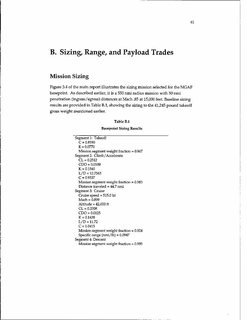
61
B. Sizing, Range, and Payload Trades
Mission Sizing
Figure 3.4 of the main report illustrates the sizing mission selected for the NGAF
basepoint. As described earlier, it is a 550 nmi radius mission with 50 nmi
penetration (ingress/egress) distances at Mach .85 at 15,000 feet. Baseline sizing
results are provided in Table B.l, showing the sizing to the 41,245 pound takeoff
gross weight mentioned earlier.
Table B.l
Basepoint Sizing Results
Segment 1: Takeoff C = 0.8190 E = 0.0770 Mission segment weight fraction = 0.967
Segment 2: Climb/Accelerate CL = 0.2512 CDO = 0.0100 K = 0.1540 L/D = 12.7563 C = 0.9537 Mission segment weight fraction = 0.983 Distance traveled = 44.7 nmi
Segment 3: Cruise Cruise speed = 515.0 kt Mach = 0.899 Altitude = 42,000 ft CL = 0.3308 CDO = 0.0125 K = 0.1438 L/D = 11.72 C = 1.0415 Mission segment weight fraction = 0.924 Specific range (nmi/lb) = 0.0947
Segment 4: Descent Mission segment weight fraction = 0.995
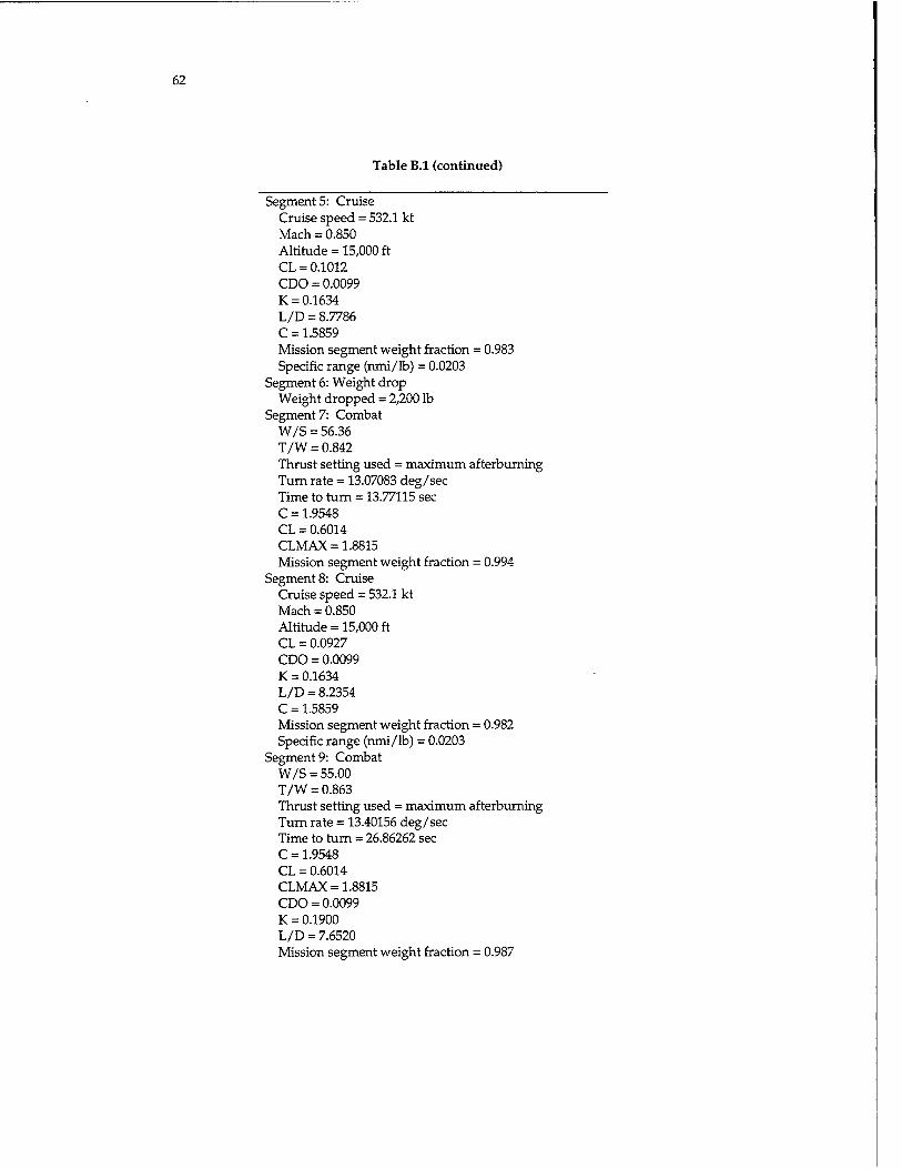
62
Table B.l (continued)
Segment 5: Cruise Cruise speed = 532.1 kt Mach = 0.850 Altitude = 15,000 ft CL = 0.1012 CDO = 0.0099 K = 0.1634 L/D = 8.7786 C = 1.5859 Mission segment weight fraction = 0.983 Specific range (nmi/lb) = 0.0203
Segment 6: Weight drop Weight dropped = 2,200 lb
Segment 7: Combat W/S = 56.36 T/W = 0.842 Thrust setting used = maximum afterburning Turn rate = 13.07083 deg/sec Time to turn = 13.77115 sec C = 1.9548 CL = 0.6014 CLMAX = 1.8815 Mission segment weight fraction = 0.994
Segment 8: Cruise Cruise speed = 532.1 kt Mach = 0.850 Altitude = 15,000 ft CL = 0.0927 CDO = 0.0099 K = 0.1634 L/D = 8.2354 C = 1.5859 Mission segment weight fraction = 0.982 Specific range (nmi/lb) = 0.0203
Segment 9: Combat W/S = 55.00 T/W = 0.863 Thrust setting used = maximum afterburning Turn rate = 13.40156 deg/sec Time to rum = 26.86262 sec C = 1.9548 CL = 0.6014 CLMAX = 1.8815 CDO = 0.0099 K = 0.1900 L/D = 7.6520 Mission segment weight fraction = 0.987

63
Table B.l (continued)
Segment 10: Climb/Accelerate CL = 0.1691 CDO = 0.0109 K = 0.1607 L/D = 10.9128 C = 0.9948 Mission segment weight fraction = 0.990 Distance traveled = 31.8988 nmi
Segment 11: Cruise Cruise speed = 515.0 kt Mach = 0.899 Altitude = 47,000 ft CL = 0.3402 CDO = 0.0129 K = 0.1429 L/D = 11.5662 C = 1.0518 Mission segment weight fraction = 0.928 Specific range (nmi/lb) = 0.1174
Segment 12: Descent Distance traveled = 50 nmi Mission segment weight fraction = 0.990
Segment 13: Loiter Loiter speed = 220.0 kt Mach = 0.333 Altitude = 500 ft CL = 0.3056 CDO = 0.0095 K = 0.1502 L/D = 12.9914 C = 1.3945 Mission segment weight fraction = 0.965
Segment 14: Landing Mission segment weight = 0.995 Reserve and trapped fuel allowance = 1.060 Fuel weight = 1759.5 lb Empty weight = 25511.5 lb Useful load (less Wf) = 3974 lb Aircraft gross weight = 41245 lb
With the addition of 6800 pounds of "internal-external fuel" volume, described in
the main report as analogous to traditional use of external tanks, mission radius
increased from 550 nmi to 994 nmi. However, at this weight the structural load
factor would drop from 7.33 to about 6.5, and maneuvering performance would
be reduced.

64
Baseline Design Sensitivity Trades
A number of commonly performed sizing sensitivity trade studies follow
(Figures B.l to B.7) to illustrate the sensitivity of this NGAF basepoint design to
parametric changes in key sizing input parameters. These include variations in
parasitic drag, drag due to lift, specific fuel consumption, dead weight (e.g., the
sized effect of any unexpected change in aircraft empty weight), payload weight,
and limit load factor. For each parametric variation, the aircraft was resized and
the resulting aircraft gross and empty weights graphed.
These charts can be used for rapid estimation of the effect of various changes in
design requirements and assumptions.
Figure B.6 shows a weights trade study of the effect of limit load factor on empty
weight for this basepoint design, at a constant takeoff gross weight (so that the
increase in empty weight due to a greater load factor results in reduced range).
In Figure B.7, the basepoint was resized to the 550 nmi mission, showing sizing
sensitivity to a change in design load factor.
Uo and We (lbs-n) Uo u.s. Cdo Project: NGAF2
-20.GO
40000
30000
20000
0 -10.00 0.00 10.00 20.00
Cdo iy. change)
Figure B.l—Sizing Sensitivity: Parasitic Drag
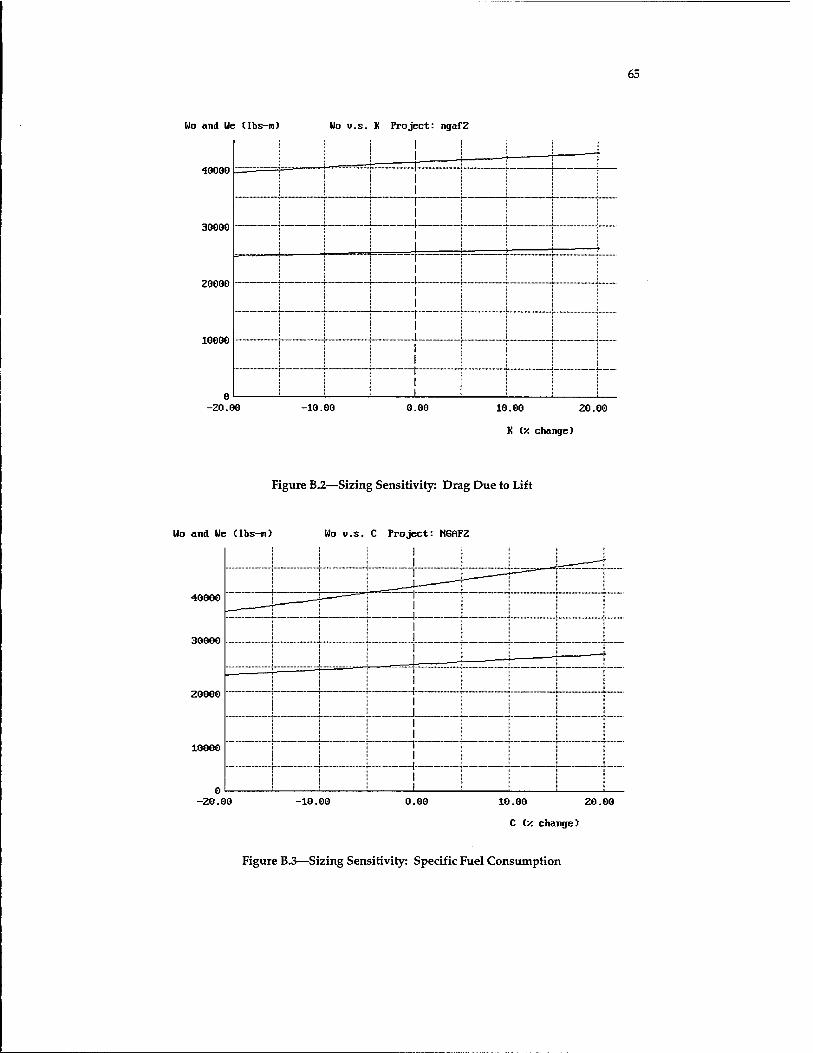
65
Uo and He (Ibs-n) Ho u.s. K Project: iigafZ
. 1 40000
0 -Z0.00 -10.00 0.00 10.00 20.00
K (x change)
Figure B.2—Sizing Sensitivity: Drag Due to Lift
Uo and Ue (lbs-m) Uo v.s. C Project: MGAFZ
1 4 1 1
40000 1 1 1 i
j 1 i |
1 I 20000
1 1
j 1 1 j 1 1
10000 j i I j
0 i j ; i
-20.00 -10.00 0.00 10.00 20.00
C ly. change)
Figure B.3—Sizing Sensitivity: Specific Fuel Consumption

66
Uo and Ue (lbs-m) Uo u.s. Dead Height Project: MGAF2
40000
30000
20000
10000
-2000 -1000 1000 2000
DEAD HEIGHT (lbs-n)
Figure B.4—Sizing Sensitivity: Dead Weight (e.g., change in We)
and Ue (lbs-m) Ho U.S. PAVLOAI (Ibs- n) Pn jject: ngaf2
40000
30000
! 20000
1 10000 |
n |
|
0 1000 2000 3000 4000 5000
As-draun Payload (lbs-n) = 2860 PASL0AD (lbs-n)
Figure B.5—Sizing Sensitivity: Payload Weight
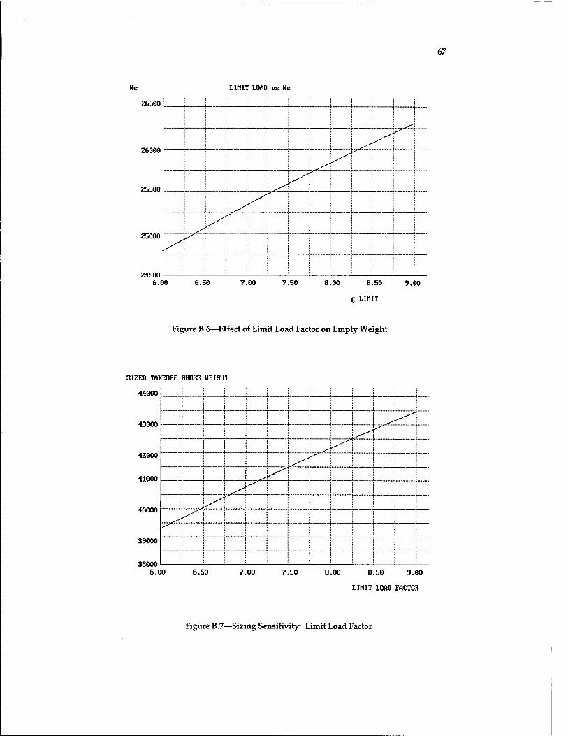
67
tie LIMIT LOAD us Ue
26500
25500
25000
74^00
6.00 6.50 7.00 7.50 8.00 8.50 9.00
g LIMIT
Figure B.6—Effect of Limit Load Factor on Empty Weight
SIZED TAKEOFF GROSS UEIGH1
44000
43000
42000
41000
40000
39000
38000 6.00 6.50 7.00 7.50 8.00 8.50 9.00
LIMIT LOAD FACTOR
Figure B.7—Sizing Sensitivity: Limit Load Factor
68
Baseline Payload Trades
Figure 4.3 of the main report shows the basepoint weapons bays, which are 137 inches long, 26 inches wide, and 26 inches high. These each hold a 1,000 pound JDAM, or a single MK-83 or Tactical Munitions Dispenser (TMD). In Figure B.8, carriage of a total of four MK-82s is shown, but note that vertical overlap is required. This complicates loading and release, would probably require some sort of "swing-away" ejector rack, and would therefore be undesirable.
In Figure B.9, external carriage of an additional six 1,000 pound JDAMs (total of
eight) is shown. Range calculations indicate a total radius of 396 nmi, a 28 percent reduction from the basepoint. In Figure B.10, external carriage of four 2,000 pound JDAMs is shown, with calculated range of 410 nmi, a 25 percent reduction from the basepoint. Note that the internal bays are left empty in this case.
The 1,000 pound JDAM was selected for the basepoint analysis, but there are strong operations effectiveness arguments in favor of carriage of the 2,000 pound JDAM instead. Some analysis indicates that the larger JDAM is required for first- day destruction of key targets, and the threat environment on the first day requires stealth so that external carriage is not an option.
Figure 4.4 of the main report shows a design trade study for increased-length internal weapons bays capable of carrying the 2,000 pound JDAM. This requires a bay stretch of about 42 inches, to a total of 179 inches, leading to a fuselage stretch of about three feet. The larger weapons bay plus the fuselage stretch will increase the empty weight by about 430 pounds. When this effect, plus the drag increase of the fuselage stretch, plus the increase in payload weight, are all accounted for, the sized takeoff gross weight increases 3 percent to 42,494 pounds. Alternatively, at an unchanged takeoff weight, the range decreases 6 percent.
This stretched, 179 inch bay also permits internal carriage of the GBU-27/B. Unfortunately, it will not permit an increase in the number of MK-82s or TMDs over the basepoint bay, as shown in Figures B.ll and B.12. That would require even more stretch of the bay and fuselage, and is probably not feasible in an NGAF-sized aircraft. Also, for the STOVL option described later, the longer bay, added to the extra length for the STOVL equipment, may drive the aircraft to an excessive total length. It may be possible to use a shorter bay only on the STOVL version, but this would further reduce commonality.
Figure B.13 summarizes the weapons carriage capabilities of the short and long bay options.

69
• BASELINE WEAPONS BAYS • VERTICAL OVERLAP WILL TRAP
SECOND STORE AND MAY COMPLICATE LOADING
Figure B.8—Four MK-82s
•Wo = 49,321 lbs
•RADIUS = 396 nm (28% REDUCTION)
(+2 INTERNAL JDAM)
Figure B.9—External Carriage of Six 1,000 lb JDAMs

70
•Wo = 48,949 lbs
•RADIUS = 410 nm (25% REDUCTION)
(BAY EMPTY)
Figure B.10—External Carriage of Four 2,000 lb JDAMs
Figure B.ll—Six MK-82s (will not fit)

71
Figure B.12—Four TMDs (will not fit)
AIM-120
«1*9
G8UZ7/B
TOD
MC64
NK-83
NK-B2
200WbJOAM
100WbJDAM
12 3 4 Number of Internal Weapons
Figure B.13—Weapons Carriage Capabilities
This stretched bay may also permit internal carriage of up to four more
AIM-120s, depending on requirements for launch trapezes, whereas the
basepoint bay is long enough only for the AIM-9 air-to-air missile. This
increased stealthy air-to-air capability may provide sufficient motivation for the
Air Force to request the longer bay. Actually, a bay stretch to only about 168
inches would permit the four more AIM-120s, with a reduced penalty compared
to the bay sized for the internal 2,000 pound JDAMs.

72
C. Basepoint Performance Analysis
The performance of the NGAF notional design concept was calculated at two midmission weights, one representing the design mission and one for the overload mission that uses "internal-external" fuel as previously described. Midmission weight was defined as 50 percent of takeoff fuel weight, with air-to- air stores retained and air-to-ground stores dropped.
For performance analysis a key input is the ratio Wi/Wo, which is the aircraft weight at which performance is to be calculated divided by the aircraft design takeoff weight. For the design mission, at a takeoff weight of 41,245 pounds, the ratio Wi/Wo at midmission is calculated to be 0.81, whereas for the overload, maximum-range mission Wi/Wo is calculated to be 0.973 at midmission weight. Table 3.4 of the main report lists the required and calculated performance for the basepoint design, including both design mission and overload mission
midmission weights.
Figures C.l through C.6 show the calculated aircraft performance including flight envelope, cruise performance (range optimization), rate of climb, and turn capabilities. Unless otherwise noted, these were calculated at design mission midmission weight. Note that according to these results, there is adequate thrust
from the nonrefanned engine.
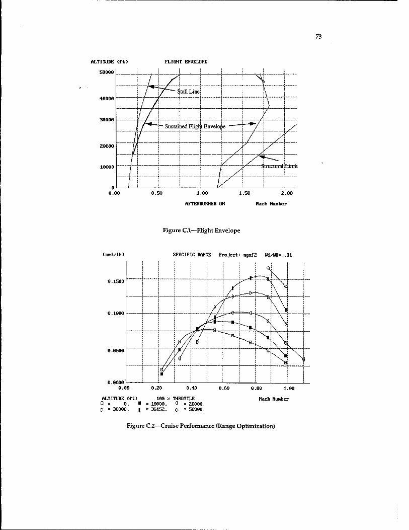
73
ALTITUDE (ft)
50000
40000
FLIGHT EHUELOPE
30000
20000
10000
0.00 0.50 1.00 1.50 Z.00
AFTERBURNER ON Nach Number
Figure C.l—Flight Envelope
(nmi/lb)
0.1500
0.1000
SPECIFIC RANGE Project: ngaf2 Ui/UO= .81
0.0500
0.0000 0.00 0.20 0.40 0.60
ALTITUDE (ft) 100 v. THROTTLE D = 0. ■ = 10000. 0 = 20000. 0 = 30000. | = 36152. o = 50000.
0.80 l.OO
Nach Number
Figure C.2—Cruise Performance (Range Optimization)

74
CfprO RATE OF CLIMB Project: ngaf2 Ui/UO= .81
60000
50000
40000
30000
20000
10000
0.00
ALTITUDE Cft) 0 = 0. I D = 30000. |
0.50
AFTERBURNER ON 10000. Ö = 20000. 36152. o = 5O0OO.
1.00 1.50
Nach Number
Figure C.3—Rate of Climb
(fpm)
60000
RATE OF CLIHB Project: ngafZ Ui/U0= 1
50000
10000
:7^2r:r^— =es=« 0.00
ALTITUDE (ft) □ = 0. I D = 30000. |
0.50
AFTERBURNER ON 10000. 0 = 20000. 36152. o = 50000.
1.00 1.50
Nach Nunber
Figure C.4—Rate of Climb at Overload Takeoff Weight

75
TURN BATE (deg/sec) MAXIMUM TURN RATE at Alt Cft) = 30000 PROJECT: ngaf2
Z0.00
15.00
10.00
5.00
0.00 0.00 0.50 1.00 1.50 2.00
Mach Number
Figure C.5—Instantaneous Turn Rate
Ps (ft/sec)
400
300
200
Ps at Alt Cft) = 30000 PROJECT: ngaf2
100
-100
-200 0.00
LOAD FACTOR Cti) D = 1. I = I = 5. o =
0.50
AFTERBURNER ON 2. Q = 3. D 6. o = 7.
1.00 1.50
Mach Number 4.
Figure C.6—Sustained Turn Rate

76
Ps (ft/sec)
400
Ps at Alt (ft) = 30000 PROJECT: ngaf2
300
ZOO
100
NAVYGROUNDRULES: 1% THRUST LOSS, "FLAT-TOP" WAVE DRAG CURVE
-100
-200 0.00
LOAD FACTOR (n) 0 = 1. I = | = 5. o =
0.50 1.00 1.50
AFTERBURNER ON Nach Number 2. a = 3. D = 4. 6. a = ?.
Figure C.7—Sustained Turn Rate: Navy Ground Rules

77
D. Joint Service Options Weight Results
This appendix details the weight results for the joint-service design study described in the main body of the report and provides the backup data for the weights results summary figure. Group weights statements for the trade study alternatives are presented below as Tables D.l to D.4. For comparison, the reader is referred to the basepoint group weight statement in Table 3.2 of the main report. (Note that all weights in the tables are in pounds.)

78
Table D.l
CV-CTOL Group Weight Statement
Fighter/Attack Group Weight Statement: File NGAF2C.DWT
Structures Group 12963.9 Wing 4521.4 Horizontal tail 0.0 Vertical tail 789.4 Fuselage 5248.6 Main landing gear 1286.7 Nose landing gear 536.6 Engine mounts 62.3 Firewall 113.0 Engine section 48.9 Air induction 356.9
Propulsion Group 6383.7 Engine(s) 4839.9 Tailpipe 0.0 Engine cooling 273.0 Oil cooling 37.8 Engine controls 21.2 Starter 72.9 Fuel system 1058.9
Equipment Group 4924.7 Flight controls 1020.8 Instruments 128.8 Hydraulics 171.7 Electrical 706.5 Avionics 1945.4 Furnishings 391.7 Air conditioning 536.0 Handling gear 23.8 Miscellaneous empty weight 3030.0 Total weight empty 27312.4
Useful Load Group 13932.6 Crew 220.0 Fuel 9958.6 Oil 50.0 Cargo 2860.0 Passengers 0.0 Miscellaneous useful load 844.0
Design gross weight 41245.0

79
Table D.2
Air Force CV-CTOL Derivative Group Weight Statements
Fighter/Attack Group Weight Statement: File NGAF2L.DWT
Structures Group 12260.0 Wing 4329.0 Horizontal tail 0.0 Vertical tail 789.4 Fuselage 5248.6 Main landing gear 930.1 Nose landing gear 381.7 Engine mounts 62.3 Firewall 113.0 Engine section 48.9 Air induction 356.9
Propulsion Group 6393.8 Engine(s) 4930.0 Tailpipe 0.0 Engine cooling 273.0 Oil cooling 37.8 Engine controls 21.2 Starter 72.9 Fuel system 1058.9
Equipment Group 4924.7 Flight controls 1020.8 Instruments 128.8 Hydraulics 171.7 Electrical 706.5 Avionics 1945.4 Furnishings 391.7 Air conditioning 536.0 Handling gear 23.8 Miscellaneous empty weight 2920.0 Total weight empty 26498.5
Useful Load Group 14746.5 Crew 220.0 Fuel 10772.5 OÜ 50.0 Cargo 2860.0 Passengers 0.0 Miscellaneous useful load 844.0
Design gross weight 41245.0

80
Table D.3
STOVL Group Weight Statement
Fighter/Attack Group Weight Statement: File NGAF2S.DWT
Structures Group 11952.5 Wing 4425.2 Horizontal tail 0.0 Vertical tail 789.4 Fuselage 4878.9 Main landing gear 930.1 Nose landing gear 381.7 Engine mounts 62.3 Firewall 113.0 Engine section 48.9 Air induction 322.9
Propulsion Group 6393.8 Engine(s) 4930.0 Tailpipe 0.0 Engine cooling 273.0 Oil cooling 37.8 Engine controls 21.2 Starter 72.9 Fuel system 1058.9
Equipment Group 4924.7 Flight controls 1020.8 Instruments 128.8 Hydraulics 171.7 Electrical 706.5 Avionics 1945.4 Furnishings 391.7 Air conditioning 536.0 Handling gear 23.8 Miscellaneous empty weight 5170.0 Total weight empty 28441.0
Useful load group 12804.0 Crew 220.0 Fuel 8830.0 Oil 50.0 Cargo 2860.0 Passengers 0.0 Miscellaneous useful load 844.0
Design gross weight 41245.0

81
Table D.4
Air Force STOVL-Derivative Group Weight Statement
Fighter/Attack Group Weight Statement: File NGAF2D.DWT
Structures Group 11650.7 Wing 4232.8 Horizontal tail 0.0 Vertical tail 789.4 Fuselage 4878.9 Main landing gear 852.6 Nose landing gear 349.9 Engine mounts 62.3 Firewall 113.0 Engine section 48.9 Air induction 322.9
Propulsion Group 6393.8 Engine(s) 4930.0 Tailpipe 0.0 Engine cooling 273.0 Oil cooling 37.8 Engine controls 21.2 Starter 72.9 Fuel system 1058.9
Equipment Group 4924.7 Flight controls 1020.8 Instruments 128.8 Hydraulics 171.7 Electrical 706.5 Avionics 1945.4 Furnishings 391.7 Air conditioning 536.0 Handling gear 23.8 Miscellaneous empty weight 3170.0 Total weight empty 26139.3
Useful load group 15105.7 Crew 220.0 Fuel 11131.7 Oil 50.0 Cargo 2860.0 Passengers 0.0 Miscellaneous useful load 844.0
Design gross weight 41245.0
83
References
Hoak, D., D. Ellison, et al., USAF DATCOM, Air Force Flight Dynamics Laboratory, Wright-Patterson AFB, OH, n.d.
Mattingly, J., W. Heiser, and D. H. Daley, Aircraft Engine Design, American Institute of Aeronautics and Astronautics, New York, NY, 1987.
O'Neil, W., "Takeoff and Landing Issues for a Common Tactical Aircraft Program," unpublished paper, Center for Naval Analyses, February 1994.
Raymer, Daniel, AIRCRAFT DESIGN: A Conceptual Approach, American Institute of Aeronautics and Astronautics, New York, NY, 1989.
Raymer, Daniel, RDS: A PC Based Aircraft Design, Sizing, and Performance System, AIAA Paper 92-4226, August 1992a.
Raymer, Daniel, Aircraft Aerodynamic Analysis on a Personal Computer, SAE Paper 932530, Aerotech 93, September 27,1992b.