RAMSEY ELECTRIC WINCH MODEL DCY/DC200...Keep yourself and others at a safe distance to the side of...
30
RAMSEY ELECTRIC WINCH MODEL DCY/DC200 FITTING & OPERATING INSTRUCTIONS Manual Part No. 10928 / 19.12.18 PART NO - 3561 / 3560
Transcript of RAMSEY ELECTRIC WINCH MODEL DCY/DC200...Keep yourself and others at a safe distance to the side of...

RAMSEY ELECTRIC WINCH
MODEL DCY/DC200
FITTING & OPERATING INSTRUCTIONSM
anual P
art
No.
10928
/ 19.12
.18
PART NO - 3561 / 3560

GUIDE TO SAFE WINCHING .............................................................................................. 3 WARNING ........................................................................................................................... 4 INTRODUCTION ................................................................................................................. 4 WINCH RATING .................................................................................................................. 4 EXAMPLE ............................................................................................................................ 4 FITTING INSTRUCTIONS ................................................................................................... 5 TYPES OF WINCH MOUNTING ......................................................................................... 5
BEHIND THE CAB ........................................................................................................... 5 Flush with Vehicle Deck using bracket part no. BM0001 .............................................. 5 Above Deck Mounting ................................................................................................... 6 Front Mounting ............................................................................................................. 7
LABELS ............................................................................................................................... 7 WIRING ............................................................................................................................... 7
WANDERLEAD REMOTE SOCKET ................................................................................ 8 EMERGENCY STOP ..................................................................................................... 10 LOAD LIMITING SWITCHES ......................................................................................... 10
TESTING ........................................................................................................................... 11 TO OPERATE WINCH ....................................................................................................... 11
FREE SPOOLING .......................................................................................................... 12 CAPACITIES ..................................................................................................................... 12 SERVICE/MAINTENANCE ................................................................................................ 12
REGULAR MONTHLY MAINTENANCE ........................................................................ 12 Yearly maintenance .................................................................................................... 12 OIL SPEC ................................................................................................................... 13 SPARES ..................................................................................................................... 13
CARE OF THE WIRE ROPE ............................................................................................. 13 WIRE ROPES ARE NOT COVERED BY WARRANTY. ................................................. 13 FITTING WIRE ROPE .................................................................................................... 13
TROUBLE SHOOTING TIPS ............................................................................................. 15 WINCH PARTS LIST ......................................................................................................... 18 SOLENOID ASSEMBLY PARTS ....................................................................................... 19 TEST PROCEDURE FOR SOLENOIDS ........................................................................... 20 TEST PROCEDURE FOR MOTOR ................................................................................... 21 INSTRUCTIONS FOR OVERHAUL OF RAMSEY ............................................................. 22 MODEL DC-200 SERIES RAM-LOK ................................................................................. 22
DIS-ASSEMBLY ............................................................................................................. 22 RE-ASSEMBLY .............................................................................................................. 26
WARRANTY ...................................................................................................................... 29 APPENDIX ......................................................................................................................... 30
BATTERIES ................................................................................................................... 30
2

GUIDE TO SAFE WINCHING
The following safety precautions must be observed at all times whilst using the winch.
Keep yourself and others at a safe distance to the side of the wire rope when pulling under load.
Never step over, stand near or guide a rope under tension.
Always use heavy-duty gloves when handling the wire rope to protect against cuts or possible burns.
Take care of the wire rope. Check regularly for signs of wear in the form of broken strands or severe kinks along its length. If there are more than 10 strands broken in any one inch of the rope's length, then it will be significantly weakened and must therefore be replaced. Wear and tear can be prevented by regular application of rope dressing available in aerosol form from your winch supplier. Oil and grease should never be used.
Always ensure that the rope is rewound neatly back onto the drum after use. If the rope is tensioned whilst unevenly wound, then loose coils can become trapped and badly damaged.
Do not drive the vehicle to pull a load on the winch wire rope, e.g. as a tow rope. Any resulting shock load could break the rope or damage the winch.
If the winch is being operated at maximum capacity, drape a heavy blanket or coat over the wire rope, halfway along its length. The blanket will reduce the speed of a snapped rope.
When recovering a vehicle, the winch hook should be attached to the towing hitch, if available, or to a strap or chain around a chassis leg or cross member. NEVER anchor the winch hook onto bumpers, or shipping/transit anchorage.
Do not allow the load to 'snatch' during a pull, as this can momentarily double, or even treble the load on the rope.
Try to position either your vehicle or the anchor point to ensure as straight a pull as possible. Use a snatch block if it is necessary to turn any corners with the rope.
When attaching the hook to the load, always double check that the hook is secure and the safety catch is fully closed. Remember that if the hook breaks away under tension, serious injury can result as the hook will travel through the air at speed.
A minimum of five wraps of rope around the drum is necessary to support the rated load. The rope to drum securing clamp is not designed to hold a load.
3

Never attempt to disengage the free spool clutch when winch is under load.
WARNING These winches are not intended for use in the lifting or moving of personnel.
INTRODUCTION PLEASE READ THIS MANUAL CAREFULLY BEFORE INSTALLATION OR OPERATION OF THE WINCH.
Ramsey Winches are widely used for commercial purposes throughout the world. As the new owner/operator of a RAMSEY WINCH, it is important that you read and digest the information contained in this Handbook. The winch is of the highest quality and has been designed to give a robust and efficient service for many years if care and attention are given at all times to correct, safe operation and maintenance.
Do not underestimate the potential danger in winching operations. Neither should you fear them. Do learn the basic dangers and avoid them. Respect for your winch and common sense in its operation, will ensure complete safety and reliability.
WINCH RATING The Ramsey Winch rating on this model refers to its maximum rated line pull, measured as the force being applied to the winch in a horizontal plane. As in the case of all winches, this refers to the first layer of rope on the drum. In most cases, when the winch is being used, there is no way of accurately determining the exact pull being applied. It is important, however, to try and establish that it is within the working capacity of both the winch and wire rope and this can be done by considering the following formulae which applies for gradients up to an angle of 45°. For wheeled vehicles, the pull required to move the load equals:
W + (W x angle of gradient). 25 60
Where W = load in tonnes and angle of gradient is in degrees.
EXAMPLE If W, the load of the vehicle is 4 tonne and is being pulled up skids, which form a gradient of 18°, the force on the rope is:
4 + (4 x 18) = 0.16 + 1.2 = 1.36 tonne. 25 60
Remember the winch pulling capacity reduces as the number of layers of wire rope increase on the drum.
4
5
If it is necessary to work beyond the limits of either the winch or wire rope, it is essential that a snatch block be employed which will enable the line pull to be nearly doubled.
If you should have any queries regarding the maximum load applied in a particular application, please do not hesitate to contact us and we will be pleased to offer our assistance.
FITTING INSTRUCTIONS
The Ramsey Winch has a world-wide reputation for toughness and reliability. The design of this long established product has been well proven over the years for many applications. To ensure the best service from your Ramsey Winch it is most important to follow these instructions for its fitting and subsequent operation.
Irrespective of how the winch is mounted it is important that adequate provision is made so that the load is transmitted into the body of the vehicle and then into the chassis.
TYPES OF WINCH MOUNTING
BEHIND THE CAB
Flush with Vehicle Deck using bracket part no. BM0001
Fit two channel or angle members between the first and second cross bearer spaced at 635mm (25"), the mounting bracket width. If fitting to a body with timber deck it may be necessary to raise mounting height and the following method is suggested. Weld or bolt 50mm (2" x 2") angle sections to the top of the channel members. Also use this method when it is necessary to clear gear linkage or other chassis protrusions. Using the mounting bracket as a jig, drill three holes 11mm (7/16") diameter each side into the channel or angle members. Remove mounting bracket and fit this to the winch with eight 3/8" diameter U.N.C. 20mm cap head screws supplied with kit.
5

Above Deck Mounting
There are two options of brackets available when installing the winch above deck. Fit to channels or angles as per the flush type and bolt through floor.
6

Front Mounting
When fitting the winch to the front of the vehicle it is essential that the chassis will take the loadings applied. In some cases it may be necessary for the chassis to be strengthened e.g. 3.5 tonne GVW vehicles and we would recommend that the winchmounting and chassis should be capable of taking loads of 3500kg. For further adviceplease contact the chassis manufacturer or dealer. For heavy chassis the winch canusually be mounted by flitch plates direct to the main frame of vehicle (never weld tochassis or drill top or bottom flanges, without the manufacturers approval).
LABELS
WIRING
ENSURE THAT CORRECT VOLTAGE WINCH IS FITTED TO THE CHASSIS. IF IN DOUBT, CONTACT THE CHASSIS MANUFACTURER.
The power feed to the winch must be capable of carrying 300 amps for 12v units and 175 amps for 24v units. The recommended cable for 12v is 315 strands of 0.40mm diameter per strand and for 24v is 196 strands of 0.40mm diameter per strand. This cable should be as short as possible to run from the batteries to winch power connection (see diagram below).
7

A high amperage isolator switch must be fitted (supplied on request), in a prominent position. The earth return is made through the winch mounting then back into the chassis of the vehicle. Whenever possible, earth the winch back to the battery. If this is impractical and earth is to the chassis, it may be necessary to upgrade the vehicle earth strap from battery to the chassis.
If earthed to chassis, ensure the connectors are clean and free of paint.
IF IN DOUBT, FIT EARTH RETURN SIZE AS RECOMMENDED FOR POWER FEED.
We would recommend that a high amperage fuse is always fitted in the circuit. These can be purchased separately from BHW Group Ltd. Please quote the following part numbers.
FU0020 300 amp fuse (for 12v winch). FU0040 200 amp fuse (for 24v winch). FU0050 Holder for above fuses. (See wiring diagram above).
WANDERLEAD REMOTE SOCKET Position female connector to accept wanderlead at convenient point and to avoid damage and water spray. Connect a 3 core 5 amp waterproof cable and secure this to avoid chaffing and route to winch position. Fit a male connector to plug into winch socket. Silicon waterproof sealant is recommended around all electrical connectors. There are kits
8

available for both single and double rear sockets. Part numbers SC0125 and SC0150. (See wiring diagram below).
9

EMERGENCY STOP
All electric winches must be fitted with an emergency stop/isolator switch within the circuit (as shown in diagram). This should be easily accessible and clearly marked. The operators should familiarise themselves with this switch before winch operation.
ON NO ACCOUNT WIRE DIRECTLY INTO WINCH.
ISOLATOR SWITCH MUST BE TURNED OFF WHEN WINCH IS NOT BEING USED.
Always keep the length of the feed wire and earth return to a minimum to avoid voltage drop.
In some circumstances when the vehicle is involved in constant use with only short distances between winching operation, it will be necessary to fit an additional heavy duty battery wired in parallel with the vehicle battery.
Keep this as close to the winch as possible.
It is also advisable in these circumstances to have the vehicle fitted with a heavy duty charging system and batteries.
The above comments also apply to vehicles operating with maximum loads imposed on the winch.
LOAD LIMITING SWITCHES
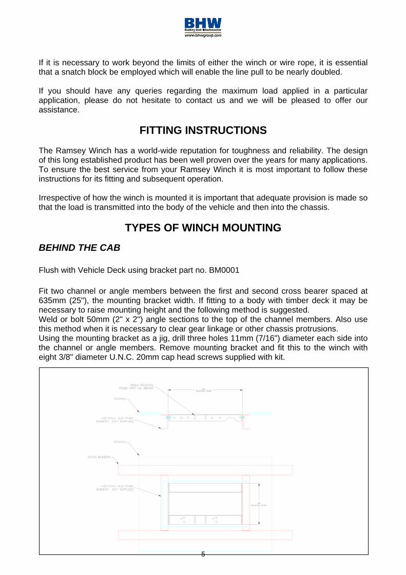
Electric load limiting switches can be supplied as an option on this model. If fitted, it is important to ensure that the winch is fitted in the correct rotation. Whilst the limit switch is calibrated to the approximate safe working load required by the customer at point of order, fine adjustment is necessary after installation. (See wiring diagram below).
10
This is supplied complete with a length of positive battery supply cable. Under no circumstances should this length of cable with shunt fitted be altered, as this will affect the functioning of the overload switch.
TESTING After the installation is complete, a proof load test of 125% of the rated load should be carried out before the winch goes into service.
TO OPERATE WINCH Turn on isolator switch, plug in wanderlead control. The winch can be powered both in and out. The load is automatically held safely when control button is released.
The best way to become acquainted with how you winch operates is to make test runs. Plan you tests in advance. Remember that you hear your winch as well as see it operate. Come to recognise the sounds of a light steady pull, heavy pull, and sounds caused by load jerking or shifting. Gain confidence in operating your winch and its use will become second nature to you. The uneven spooling of wire rope whilst pulling a load, is not a problem, unless there is a pile up of rope on one end of the drum. If this happens, reverse the winch to relieve the tension on the rope and move your anchor point further to the centre of the load. After the job is complete, you can unspool and rewind the wire rope neatly.
11

FREE SPOOLING
Ram-Lock Clutch To release clutch, power out winch until tension is released from cable. Pull out handle on side of casing and turn 90°. To re-engage, turn lever back to horizontal position. Turn drum slowly by pulling out cable. The handle, which is spring-loaded, will automatically re-engage. Ensure that handle is fully engaged before imposing load on winch.
Capacities
The Ramsey Winch is rated at 3630kg (8000lbs) and this refers to its safe working load, measured as the force being applied to the winch in a horizontal place. As in the case of all winches, this refers to the first layer of rope on the drum.
SERVICE/MAINTENANCE
REGULAR MONTHLY MAINTENANCE
Externally: The winch should be kept clean in order to prevent any build up on corrosion on external working parts. Greasing of roller guides (if fitted) at grease points (one for each roller). Also check for: Rollers revolving Slight or deep grooving Excessive wear on rollers
NOTE: If roller guides are worn excessively, wire rope life will be reduced and roller guides should be replaced.
Check winch for external damage. Check winch mounting for distortion and re-tighten mounting bolts if necessary. Operate free spool clutch mechanism to ensure correct operation, giving full engagement and disengagement. All external-moving parts should be lubricated with lightweight oil. Check oil level in gearbox and replenish with EP90 gear oil.
Yearly maintenance
In addition to the above maintenance change the oil in winch gearbox and spur box. Refill to oil level plugs.
12

OIL SPEC
Spur gearbox S.A.E. 20 (½ pint) 0.29 litres
Worm housing E.P.90/140 (1 pint) 0.58 litres
Check tightness of mounting bolts and electrical connections regularly.
SPARES Should it become necessary to obtain replacement parts, refer to list shown. Please contact us quoting serial numbers and model number. BHW Group Ltd reserve the right to change specification without notice.
CARE OF THE WIRE ROPE
It is most important that the wire rope is inspected on a regular basis, for kinks, flat spots, broken strands and other damage, and if necessary the damaged sections should be cut away and the rope re hooked or completely replaced.
It is good practice to regularly use rope lubricant, obtainable from us if required, as this will prevent rust and corrosion, which can seriously reduce its working life.
A good habit to form is that of rewinding the rope onto the winch drum after it has been used, so that it is evenly layered. To do this, rewind keeping the rope under tension. Normally the load can be applied by hand.
Under no circumstances wrap the wire rope around the load being recovered and then attach the hook back on to the rope. This will result in serious rope damage or breakage.
Always employ a chain or webbing strap from the hook to the load.
WIRE ROPES ARE NOT COVERED BY WARRANTY.
FITTING WIRE ROPE
Unwind cable on floor behind vehicle; pass through roller and secure cable to the drum-using setscrew provided. Operate winch, using wanderlead and wind on cable whilst keeping it under tension, and layer the rope on as evenly as possible. The winch is now ready for use.
13

14

TROUBLE SHOOTING TIPS
CONDITION POSSIBLE CAUSE CORRECTIONCLUTCH INOPERATIVE OR BINDS UP.
1) Dry or rusted shaft.2) Bent yoke or linkage.
1) Clean and lubricate.2) Replace yoke or shaft
assembly.3) Clutch jaws are in
contact.3) See techniques of
operation.OIL LEAKS FROM HOUSING
1) Seal damaged or worn. 1) Replace seal
2) Too much oil. 2) Drain excess oil. Refer totechniques ofoperation.
CABLE DRUM WILL NOT FREE SPOOL.
1) Winch not mountedsquarely, causing endbearings to bind drum.
1) Check mounting, refer towinch mounting Page 4
CABLE BIRD NESTS WHEN CLUTCH IS DISENGAGED.
1) Drag brake disc worn. 1) Replace discs.
MOTOR RUNS IN ONE DIRECTION ONLY.
1) Inoperative solenoid orstuck solenoid.
1) Jar solenoid to free contacts.Check by applying 12volts tocoilterminal (it should make anaudible click when energised).
2) Inoperative switch. 2) Disengage winch clutch orremove armature lead.Removeswitch plug from hood. Raiseconnector cover on hood andwith screw driver, short thebottom two pins. Solenoidshould click. Short the two lefthand pins. The other solenoidshould operate. If bothsolenoids
operate, check for a brokenwirein switch cable.
3) Broken wire or badconnection.
3) Check for loose connection onswitch and switch connector.
MOTOR RUNS BUT DRUM DOES NOT TURN.
1) Clutch not engaged.2) Sheared drum shaft
key.3) Stripped bronze gear.4) Parted shaft.
1-4) If clutch engaged butsymptom
still exists, it will be necessary to disassemble winch to determine cause and repair.
15

TROUBLE SHOOTING (cont'd.) CONDITION POSSIBLE CAUSE CORRECTIONMOTOR RUNS EXTREMELY HOT
1) Long period of operation. 1) Cooling-off periods areessential to prevent overheating.
MOTOR RUNS, BUT WITH INSUFFICIENT POWER OR WITH LOW LINE SPEED.
2) Insufficient battery. 2) Check battery terminal voltageunder load. If 10 volts or less,replace or parallel anotherbattery to it at motor terminal.
3) Electrical cables frombattery to winch toosmall.
3) Must be correct size andcapacity electrical cable for thevoltage
4) Bad electricalconnections.
4) Check all connections forlooseness or corrosion;Tighten, clean and grease.
5) Insufficient chargingsystem.
5) Replace with larger capacitycharging system.
MOTOR WILL NOT OPERATE
1) Isolator switch notturned on.
2) Fuse has blown.
3) Break in power lead orextension socket.
4) Inoperative solenoidor stuck solenoid.
1) Turn on isolator switch.
2) Replace fuse.
3) Repair or replace wiring.
4) Jar solenoid to free contacts.Check by applying 12voltsto coil terminal (it shouldmake an audible click whenenergised).
5) Inoperative switch. 5) Disengage winch clutch orremove armature lead.Remove switch plug fromhood. Raise connector coveron hood and with a screwdriver, short the bottom twopins. Solenoid should click.Short the two left pins. Theother solenoid should operate.If both solenoids operate,check for a broken wire inswitch cable.
16

TROUBLE SHOOTING (cont'd.) CONDITION POSSIBLE CAUSE CORRECTION
MOTOR WILL NOT OPERATE
6) Inoperative motor. 6) If solenoids operate, checkfor voltage at armature post,replace motor.
7) Loose connections. 7) Tighten connections on bottomside of hood and on motor.
17

WINCH PARTS LIST
Item No.
Qty. Req'd
Part No.
Description ItemNo.
Qty. Req'd
Part No.
Description
1 1 276028 Shifter Assembly* 19 1 342023 Key-Square 2 1 278027 Solenoid Assembly-12V 20 1 342033 Key-Square
278028 Solenoid Assemb!y-24V 21 1 356901 Shaft-Spur3 1 282001 Switch Assembly 22 1 357479 Shaft-Drum-Std 4 1 302808 Angle (std) 1 357481 Shaft-Drum-Mod Y 1 302811 Angle (mod Y) 23 1 368001 Worm-R.H. – 60:1 5 1 302809 Angle (std) 1 368019 Worm-R.H. – 46:1 1 302810 Angle (mod Y) 24 3 402001 Bearing Needle 6 1 316083 Cap- Bearing 25 2 402002 Bearing Ball 7 1 324160 Jaw Clutch 26 4 412003 Bushing 8 1 328134 Cover-Worm Gear Hsg 27 1 412045 Bushing 9 1 328106 Cover-Spur Gear Hsg 28 22 414038 Capscrew 1/4 -20NC x 3/4 LG Hex HD z/p
GR5. 10 1 332007 Drum –Mod Y 29 4 414045 Capscrew 1/4 -20NC x 7/8 LG Hex HD
GR5. 1 332105 Drum-Std 30 3 414059 Capscrew 1/4 -20NC x 1 LG Hex HD z/p
11 1 334001 Idler Gear 31 1 414279 Capscrew 3/8 -16NC x 3/4 LG Hex HD GR5.
12 2 334003 Gear 32 6 414282 Capscrew 3/8 -16NC x 1-1/4 LG Hex HD z/p GR5.
13 1 334129 Pinion 33 4 414845 Capscrew 1/4 -20NC x 1 LG Soc Hd Nyloc 14 1 334161 Gear R.H. –60:1 34 2 414856 Capscrew 1/4 -20NC x 3/4 LG Soc Hd z/p
1 334163 Gear R.H. – 46:1 35 1 414912 Capscrew 3/8 -16NC x 5/8 LG Soc Hd 15 1 336010 Handle 36 1 416029 Setscrew 1/4 -20NC x 5/16 LG Soc Hd 16 1 338203 Housing-Spur Gear 37 1 416030 Setscrew 1/4 -20NC x 3/8 LG Soc Hd (Full
Dog Point) 17 1 338208 Housing-Clutch 38 1 416059 Setscrew 1/4 -20NC x 3/8 LG Soc Hd 18 1 338273 Housing-Gear 39 3 418040 Nut 3/8 – 2NF Hex Reg z/p
18

Item No.
Qty. Req'd
Part No.
Description ItemNo.
Qty. Req'd
Part No.
Description
41 10 418177 Lockwasher 3/8 Med Sectz/p
67 1 494053 Spring
42 2 438014 Drag Brake 68 3 518002 Thrust Washer 43 1 442184 Gasket 69 1 518014 Thrust Washer 44 1 442185 Gasket 70 2 518015 Thrust Washer 45 1 442205 Gasket 71 1 518018 Fibre Washer 46 1 450001 Key 47 2 450006 Key – Barth 48 4 450016 Key - Barth 49 1 456001 Lub Fitting 50 2 456008 Relief Fitting 51 1 458001 Motor-12V 1 458005 Motor- 24V52 1 462015 O-Ring53 2 468002 Reducer 54 2 468011 Pipe Plug Sq Hd 55 2 468017 Pipe Plug Soc Hd 56 1 468018 Pipe Plug Soc Hd 57 2 470001 Pin 58 1 470033 Spirol Pin 59 1 472012 Plug 60 1 472013 Plug 61 1 482013 Rubber Boot 62 1 486009 Oil Seal 63 1 486017 Oil Seal 64 1 486023 Oil Seal 65 1 490003 Snap Ring 66 2 494002 Spring
SOLENOID ASSEMBLY PARTS
Item No.
Qty. Req'd
Part No.
Description
1 1 289009 CABLE-BOLT ASSY 2 3 289077 WIRE ASSEMBLY 3 1 289091 WIRE ASSEMBLY 4 2 364001 STRAP 5 2 364002 STRAP 6 1 408035 SOLENOID BRACKET 7 2 416216 SCREW 8 2 416227 SCREW 9 4 418004 NUT 10 2 418022 NUT 5/16-18NC Hx REG11 2 418140 FLAT WASHER 10 12 1 418153 LOCKWASHER 5/16
MED SECT 13 1 418154 LOCKWASHER 5/16
INTERNAL 14 1 418155 LOCK WASHER 5/16
EXTERNAL 15 1 430013 FEMALE CONNECTOR16 2 440071 TERMINAL TAB 17 2 440110 SOLENOID 12V 2 440114 SOLENOID 24V 18 1 472010 COVER 19 1 482029 COVER CONNECTOR 20 4 530106 COVER TERMINAL
19

TEST PROCEDURE FOR SOLENOIDS
Steps to follow when testing current flow through DC solenoids.
It should be noted that when testing a 12-volt or 24 volt solenoid the DC motor and battery must be of the same voltage.
To test the solenoids: (See figure 1)
1. Securely clamp a motor to a bench or worksurface.
2. Attach a jumper wire from (A) terminal on themotor to one of the field terminals on the motor,(F-2).
3. Attach the other motor field terminal (F-1) to oneof the side terminals of the solenoid.
4. Ground the solenoid to the motor with a wire asshown.
5. Attach positive (+) battery wire to the oppositeside terminal of the solenoid. Ground the negative(-) battery wire to the motor housing.
6. Touch "hot" wire, from the positive batteryterminal, to small terminal of the solenoid.
7. The motor should now be running if the solenoidis good. If not, make sure the motor will rundirectly from the battery.
8. To test the upper contacts use the same hook-up except use the top terminals.(See figure 2).
When the "hot" wire is touched to the smallterminal the motor will stop operating.
The top terminals are normally closed i.e.:connected, and the side terminals open, or notconnected. When the solenoid operates, the topterminals are disconnected and the sideterminals are connected.
Take care not to bring hot wires into contact withground in order to prevent electrical arcing.
20

TEST PROCEDURE FOR MOTOR The Ramsey Winch motor is a 4 pole, 4 coil wound 12 volt or 24 volt DC motor.
The 4 pole, 4-coil feature provides high torque at low speeds
To test the motor to determine if it is functioning correctly, firstly securely fasten the motor to a bench or work surface so it will not jump or move around during test procedure (the starting torque of motor is high).
1. Connect a jumper wire (at least anumber 25mmsq 170-amp wire) from F-1 to A motor terminals (See fig. 1)
2. Attach a wire (at least a number25mmsq 170-amp wire) from positive(+) battery terminal to F-2 motor themotor and battery terminal. Groundnegative (-) battery terminal to motorhousing (See fig. 2). Motor should nowrun.
To reverse the direction of rotation:
1. Attach jumper wire from F-2 to (A)motor terminals (See fig. 2).
2. Attach wire from positive (+) batteryterminal to F-1 motor terminal. Groundnegative (-) battery terminal to motorhousing. (See fig. 2).
NOTE: Always attach battery wire solidly to motor terminals. Make and Break the connection of the negative (-) battery terminal at the motor housing. This avoids burning the motor terminals. CAUTION: Do not run the motor for a long period of time in fashion mentioned above, because the motor could become damaged.
21

The motor running idle on the bench will draw 55 amperes and must run free and easy. If the ampere draw is more than 60 amps and the motor runs rough or has a strange sound, it should be replaced.
With the motor attached in place on a winch (less cable on drum) the ampere should be approx. 65 to 70 amps.
If after following the procedure outlined the test on the winch significantly exceeds 70 amperes refer to your Owners Manual for troubleshooting suggestions on the mechanical portion of the winch.
See fig. 3 for the solenoids connection to
INSTRUCTIONS FOR OVERHAUL OF RAMSEY MODEL DC-200 SERIES RAM-LOK
DIS-ASSEMBLY
1. Drain oil from worm gear housing byremoving (item. 54) plug from bottomof gear housing. Remove relief fittingand reducer (items 50 & 53) from topof gear housing. Remove mountingangles (items 4 & 5) from winch byremoving hardware shown.
2. Drain oil from spur gear housing byremoving (item 54) plug. Removecover and gasket (items 9 & 44) fromspur gear housing by unscrewingtwelve capscrews (item 28). Slide gear(item 12) from end of worm shaft (item23). Remove spur gear shaft (item 21),with gears attached. Check bearings(item 24) and thrust washers (item 68)for signs of wear, replace if necessary.Remove old bearings and press newbearings into place.
22

Remove solenoid assembly (item 2) by unscrewing capscrews (items 30 & 34). Disconnect solenoid cables from motor (item 51). Make note of which terminals cables are attached to.
3. Remove key (item 19) and snap ring(item 65) from worm shaft. Removemotor (item 51) from spur gear housing(item 16) by removing (3) nuts andlockwashers (items 39 & 41). Unscrew(4) capscrews (item 34) to remove spurgear box (item 16) and gasket (item43) from gear housing. Replace lipseals (items 62 & 64) by pressing oldseals from spur gear housing andpressing new seals into place.
4. Slide clutch housing (item 17) from endof drum shaft. Slide jaw clutch (item 7)from end of drum shaft.Remove (2) keys (item 47) fromkeyways. A screw driver can be used,at notch, to aid in removal of keys.Once keys have been removed, drum(item 10) and thrust washer (item 70)can be removed from drum shaft.Parts under drum, thrust washer (item69), spring disc (items 66 & 42) shouldalso be removed.
5. Remove bearing cap (item 6) fromgear housing by unscrewing fourcapscrews (item 29). Remove worm(item 23) and bearing (item 25) fromgear housing. Use a soft hammer togently tap input end of worm and driveworm and bearing from gear housing.Once worm has been removed fromhousing, bearing can be pressed fromend of worm.Check for signs of wear to worm (item23) and bearings (item 25). Replace ifnecessary.
23
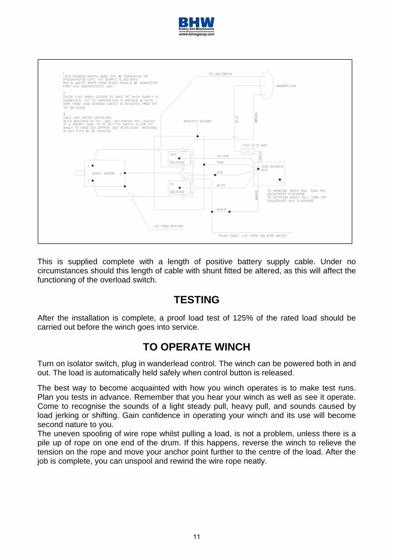
6. Remove gear housing cover (item 8)from gear housing (item 18) byunscrewing five remaining capscrews(item 28). Place capscrews into twotapped holes of cover and tighten. Thiswill pull the cover loose from gearhousing.
Remove cover gasket (item 45) and pullshaft (item 22), with gear attached, andthrust washer (item 70) from gearhousing.
7. Check for signs of wear on gear teeth.If replacement of gear is necessary,gear must be replaced as follows:
1. Press gear (item 14) from shaft (item22).
2. Examine shaft keys and keyways. Ifdistortion of keys and/or keyways areevident, shaft and keys should bereplaced.
3. Use a soft hammer to gently tap keys(item 48) into keyways. Press gear(item 14) over shaft and keys. Gearmust be centred over keys.
8. Remove seal (item 63) from back ofgear housing (item 18). Check bushing(item 27) for signs of wear. Pressbushing (item 27) from gear housingand replace if necessary. Press newbushing and seal back into place.
24

9. Check drum bushings (item 26) forsigns of wear. Replace if necessary bypressing old bushings from drum (item10) and pressing new ones into place.
10. Examine shifter assembly (item 1) fordamage to yoke. Yoke should be firmlyattached to shaft, yet, able to swivelfreely around shaft. Replace ifnecessary by removing pin (item 58)from handle (item 15). Remove rubberplug (item 59) from housing. Unscrewsetscrew enough to allow shifterassembly to be removed from housing.
Check clutch housing bushing (item26) for signs of wear. Remove ifnecessary by pressing old bushingfrom housing (item 17) and pressingnew one into place.
Install new shifter assembly (item 1) by placing end of shaft, opposite yoke, through spring (item 67) and into housing (item 17). Attach (item 15) handle to shaft using roll pin (item 58). Tighten setscrew, in housing, enough to allow shifter assembly to operate properly. Replace rubber plug.
11. Check cover bushing (item 8) for signsof wear. Replace if necessary byremoving old bushing and pressingnew bushing into place.
12. Check pinion gear on motor for signsof wear. If necessary replace gear(item 13), O-ring, (item 52) and fibrewasher (item 71) as follows:
A. Place fibre washer (item 71) and welloiled O-ring (item 52) over end ofmotor shaft and down to bottom ofshaft.
B. Insert key (item 46) into motor shaftkeyway. Slide pinion gear over shaftand key. Use a hammer and 7/8” I.D.
25

tube to drive pinion down hard enough to seat O-ring (item 52) into groove in bottom of pinion gear.
C. Slide pinion gear up toward end ofshaft so that there is a 1-13/16”distance from top of gear to castsurface below gear. Tighten setscrew(item 36) securely enough to preventpinion gear from moving on motorshaft.
13. Check gears of spur gear shaftassembly for signs of wear, replace ifnecessary. Press old gears from shaft(item 21). Tap key (item 20) intokeyway of shaft (item 21). Press shaftthrough gears so that gears arecentred on shaft and key.
RE-ASSEMBLY
14. Apply grease to end of shaft, oppositegear. Apply grease to bushing in gearhousing (item 18). Place greased endof shaft through thrust washer (item71) and bushing in gear housing (item18). Place gasket (item 45) onto gearhousing cover (item 8). Apply grease togear end of shaft and bushing in cover.Place cover onto shaft and secure tohousing with five (item 28) capscrewsat the five lower most holes.
15. Place winch, with gear housing coverdown, on work bench. Drum shaftshould be in vertical position. Slidethrust washer (item 69) over drumshaft and slide downwards until washerrests on gear housing. Set springs(item 66) and drag brake disc (item 42)into pockets of gear housing. Greasebushings in drum (item 10). Slide drumassembly onto drum shaft with drumjaws upward.
26
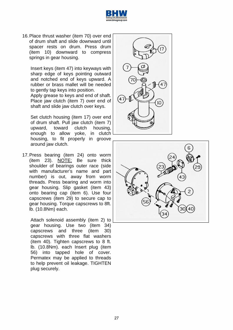
16. Place thrust washer (item 70) over endof drum shaft and slide downward untilspacer rests on drum. Press drum(item 10) downward to compresssprings in gear housing.
Insert keys (item 47) into keyways withsharp edge of keys pointing outwardand notched end of keys upward. Arubber or brass mallet will be neededto gently tap keys into position.Apply grease to keys and end of shaft.Place jaw clutch (item 7) over end ofshaft and slide jaw clutch over keys.
Set clutch housing (item 17) over endof drum shaft. Pull jaw clutch (item 7)upward, toward clutch housing,enough to allow yoke, in clutchhousing, to fit properly in groovearound jaw clutch.
17. Press bearing (item 24) onto worm(item 23). NOTE; Be sure thickshoulder of bearings outer race (sidewith manufacturer’s name and partnumber) is out, away from wormthreads. Press bearing and worm intogear housing. Slip gasket (item 43)onto bearing cap (item 6). Use fourcapscrews (item 29) to secure cap togear housing. Torque capscrews to 8ft.lb. (10.8Nm) each.
Attach solenoid assembly (item 2) togear housing. Use two (item 34)capscrews and three (item 30)capscrews with three flat washers(item 40). Tighten capscrews to 8 ft.lb. (10.8Nm). each Insert plug (item56) into tapped hole of cover.Permatex may be applied to threadsto help prevent oil leakage. TIGHTENplug securely.
27

18. Press bearing (item 24) onto worm andinto worm gear housing. NOTE: Besure thick shoulder of bearings outerrace (side with manufacturer’s nameand number) is out, away from wormthreads. Place gasket (item 43) ontospur gear housing (item 16). Securespur gear housing to worm gearhousing using four capscrews (item33). Torque capscrews to 8 ft. lb.(10.8Nm). each.Mount motor (item 51) to spur gearhousing (item 16) using threelockwashers and nuts (items 39 & 41).Attach solenoid cables to motorterminals. Tighten all nuts securely.
19. Place snap ring (item 65) over end ofworm shaft (item 23) and set into snapring groove. Insert key (item 19) intokeyway of worm shaft. Place thrustwasher (item 68) over each end of spurgear shaft (item 21). Set spur gearshaft assembly into bearing of spurgear housing. Slide gear (item 12) and(item 68) thrust washer over end ofworm shaft (item 23).
Insert pins (item 57) into cover (item91). Place gasket (item 44) ontocover. Attach cover and gasket to spurgear housing using twelve capscrews(item 28). Torque capscrews to 8 ft.lb.(10.8Nm). each.
Insert plug (item 54) into bottom ofspur gear housing. Permatex may beapplied to threads to help prevent oilleakage.Remove reducer and fitting (items 50& 53) from top of spur gear housing.Pour ½ pint of SA 20 weight motor oilinto spur gear box. Replace reducerand fitting into top of spur gearhousing. Tighten reducer and fittingsecurely.
28

20. Attach mounting angles (items 4 & 5)using six capscrews (item 32) withlockwashers and capscrews (items 35& 31). Torque capscrews to 34 ft. lb.(46Nm). each. Insert plug (item 54).Into bottom of gear housing. Permatexmay be applied to threads to helpprevent leakage.Pour ¾ pint of EP 140 gear oil intohousing thru hole in top of housing.Insert relief fitting (item 50) intoreducer (item 53). Reducer shouldthen be placed into hole on top of gearhousing. Tighten fitting and reducersecurely.
WARRANTY
RAMSEY WINCHES - ONE YEAR LIMITED WARRANTY
BHW GROUP LTD the authorised Ramsey Servicing Distributor in the UK and Ireland warrants each new winch and ancillary equipment supplied against factory defects in material and workmanship for one year from date of purchase.
The responsibility for removing the winch or ancillary equipment is the owner's together with its return, transportation prepaid to BHW Group Ltd.
BHW Group Ltd will, under this Warranty, without charge repair or replace at its option, parts which on inspection are deemed to be defective. The loss of use of the produce, loss of time, inconvenience, commercial loss or consequential damages are not covered.
Warranty does not apply where the product has been tampered with or altered in any way, or where the serial number or date stamp has been defaced, altered or removed, or if in the view of BHW Group Ltd the damage or failure occurred from misuse, negligence or accident.
THIS WARRANTY EXCLUDES THE WIRE ROPE
Ramsey Winch Co. and BHW Group Ltd reserve the right to change the design of any product without assuming any obligation to modify any product previously supplied. Winches or equipment returned under warranty should be despatched to BHW Group Ltd Service Department at the address indicated below, with full name and address of sender, and a statement detailing the defect.
29

APPENDIX
BATTERIES As a result of radical changes in vehicle battery design and performance that have taken place over the last 18 months it is essential that the correct type are specified on new vehicles that will include an electric winch or other high electrical power consumer. Heavy Duty ED3/VB3 rated should be specified as these are vibration proof and have 2.5mm thick plates compared to the standard 1.5mm. They also have glass wool separators which reduces the leeching problem. Thee operating duty cycle for this class of battery is 14 compared to only 6 on a standard battery. For extra heavy duty applications where high start up surges are required Holchstrom Gel filled batteries should be specified which have a flat instead of declining rate of discharge. These offer up to a 40% increase of cold start performance for a battery of the same physical size.
Incorrect type will cause problems for vehicles using equipment requiring high DC Power consumption such as an electric winch, flashing beacons and work lights. A standard amp hour rating is used for all batteries and this indicates the amperage available when a constant discharge is achieved over 20 hours. As an example a battery with an amp hour rating of 75 means the battery can carry a load of 3.75 amps for 20 hours. Vehicle manufacturers’ requirements have changed due to improved engine efficiency and many now require hundreds of amps for a few seconds for starting and to save space they demand small lightweight batteries. These batteries are designed to discharge around 15% of their total capacity and then recharge quickly from the alternator. The duty cycle design criteria for vehicle batteries is to crank a cold engine for 10 seconds and then rest for 1 minute allowing the battery to recover and the starter motor to cool down. The engine would normally have started consuming equipment like a DC winch is operated for much longer periods of time with only short breaks and then recharged this is referred to as deep cycling. In winching applications the battery is continuously subjected to deep cycling and recharging this will result in premature loss of battery capacity.
The new generation of starter batteries are now light duty designed to retain 75% - 85% charge throughout their working life with a maximum duty cycle of 6 – 7. If they are used for winch or similar applications and the voltage falls to 12.2v soft lead sulphate deposits on the plates and separators. If left discharged for a period of around 70 hours the lead sulphate hardens and crystallises forming an insulation barrier preventing it from accepting a charge and effectively causing irreparable damage. All popular traditional batteries leech between the plates when not in use particularly in warmer weather causing a self discharge. In poor quality batteries this problem is worse. 24v systems using two 12v batteries of this type:- If one battery deteriorates and becomes weak it will resist charging and the stronger battery will take precedence. A voltage reading of 25-26v may be measured but under the very high load during winching this will reduce dramatically putting excessive strain on the good battery causing it to fail prematurely.
30