
Ramsdengçös eye piece
27
POWER POINT PRESENTATION TOPIC: RAMSDEN’S EYE –PIECE BY:- PROF.S.V.ANGADI, PHYSICS DEPARTMENT, J.T.COLLEGE, GADAG
-
Upload
shivanand1964 -
Category
Education
-
view
5 -
download
0
Transcript of Ramsdengçös eye piece

POWER POINT PRESENTATION
TOPIC: RAMSDEN’S EYE –PIECE
BY:- PROF.S.V.ANGADI,
PHYSICS DEPARTMENT, J.T.COLLEGE,GADAG

RAMSDEN’S EYE – PIECE
The eye piece consisting two Plano - convex lenses L1 and L2. Let the focal length the field lens be f1 = f and the eye lens be f2= f. The separation between the two lenses is kept equal to 2f/3 to satisfy the condition of chromatic aberration. The convex surfaces of the two lenses are made to face each other and the eye piece is placed beyond the image formed by the objective of the instrument.

CONDITION OF CHROMATIC ABERRATION:

This means the field lens should be placed at the focal plane of the eye lens. In this position any dust particle or scratch on the field lens would be magnified equally the final image, hence the final image would spoiled. To avoid this, the distance between the two lenses is kept to 2f/3. This does not cause much departure from the achromatism

Condition of spherical aberration :
The spherical aberration is reduced using both piano convex lenses and their convex surfaces facing each other.

Working:

An eye piece is adjusted for normal vision forms the final image at Infinity. The image I2 formed by the field lens lies at the first focal plane of the eye lens. The focal length of eye lens is f and the distance between the two lenses is 2f /2, thus the image 12 lies at distance f/3 to the left of the field lens

For the field lens the Image l1 formed by the objective of the Instrument acts as an object. If u is the object distance and v = {f/3 - (2f/3)] = - f/3 be the image distance, then we can have from lens formula.

1F= 1v − 1u
But we have
f1=f2=f
1f = 1−f 3ൗ�− 1u 1u = 1f + 3f
u = − f4

The negative sign of u Indicates that the Image I1 formed by the objective lies to the left of the field lens. The rays coming from I2 after emerging from the eye lens as a parallel beam.

EQUIVALENT FOCAL LENGTH:

The focal length of equivalent lens is
F= f1xf2 f1+ f2− d
F= fxf f+ f− 2f 3ൗ�
F= 3f4

For the final Image is to form at Infinity, 12 should be at the first focal plane of equivalent lens. Therefore the equivalent lens should be placed at a distance 3f/4 to the right of 12 or at distance 3f/4 - f/4 = f/2 to the right of field lens

Cardinal points:

There are six Cardinal points, two principal point, two focal points and two nodal points.

PRINCPAL POINTS:

POSITION OF FIRST PRINCIPAL POINT:
The distance of the first principle point H1 from the field lens L1 be α1 is given by α1 = Fdf2 = ሾ2f/3ሿሾ3f/3ሿf = f2
This means the first principle point H1 lies at distance f/2 to the right of field lens L1.
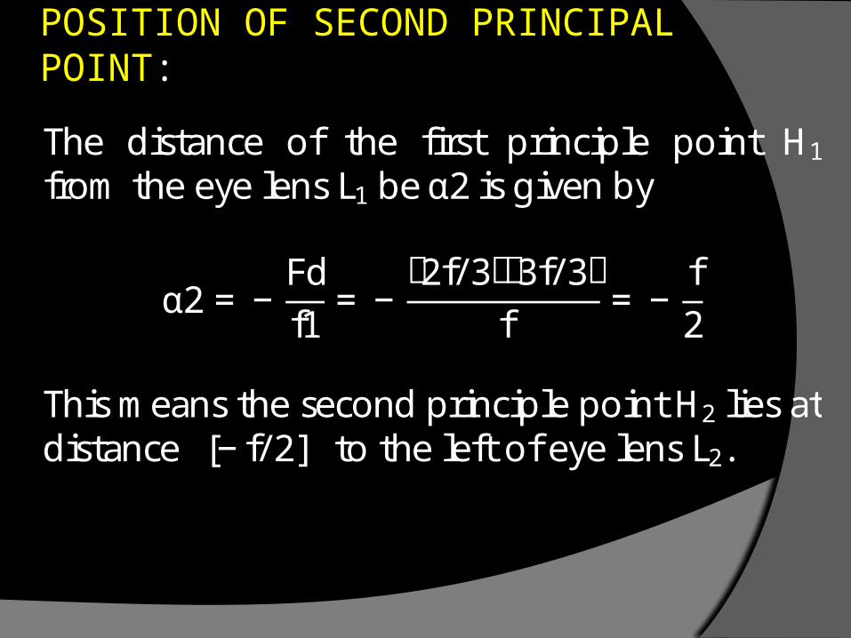
POSITION OF SECOND PRINCIPAL POINT:
The distance of the first principle point H1 from the eye lens L1 be α2 is given by α2 = −Fdf1 = −ሾ2f/3ሿሾ3f/3ሿf = − f2
This means the second principle point H2 lies at distance [−f/2] to the left of eye lens L2.
FOCAL POINTS:

POSITION OF FIRST FOCAL POINT:
The distance of the first focal point F1 from the field lens L1 be β1 is given by β1 = −F1− df2൨= −3f4 1− 2f/3f ൨= −3f4 x13 = − f4 This means the first focal point F1 lies at distance −f/4 to the left of field lens L1.
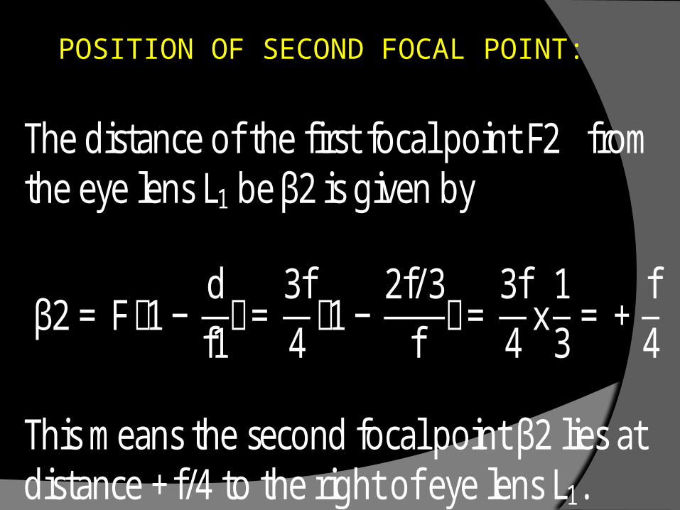
POSITION OF SECOND FOCAL POINT:
The distance of the first focal point F2 from the eye lens L1 be β2 is given by β2 = F1− df1൨= 3f4 1− 2f/3f ൨= 3f4 x13 = + f4 This means the second focal point β2 lies at distance +f/4 to the right of eye lens L1.
Nodal points: -
The medium on either side of the eye piece Is same; the nodal points N1, N2 coincide with the principle points H1, H2 respectively.

Ramsden’s eye piece is positive eye piece:
The first focal point of Ramsden's eye piece Is used to examine a real object or the real image therefore It is called a positive eye piece.
It is used in telescopes and other optical instruments where the accurate measurements of distances and angles are made with it

POSITION OF CROSS WIRES:
In order to form final the image at infinity, the Image formed by the objective of the instrument should be at the focal plane F1 of the of the eye piece. The cross wires should also be in focus with the final Image. Therefore the cross wires should place at the first focal point of the eye piece

END