R&D Report 1956-33
43
PRIVATE AND CONFIDENTIAL RESEARCH DEPARTMENT A VISIT 10 THE UN·ITED STATES OF AMERICA JUNE 10th-JULY Illth, 1956 'Report No. A-Oij3 ( 1956/33) THE BRITISH BROADCASTING CORPORATION ENGINEERING DIVISION
Transcript of R&D Report 1956-33
PRIVATE AND CONFIDENTIAL
RESEARCH DEPARTMENT
A VISIT 10 THE UN·ITED STATES OF AMERICA
JUNE 10th-JULY Illth, 1956
'Report No. A-Oij3
( 1956/33)
THE BRITISH BROADCASTING CORPORATION
ENGINEERING DIVISION

RESEARCH DEPARTMENT
A VIS~T TO THE UNITED STATES OF AMERICA
JUNE 10th-JULY Jl.J.th 1 1956
Report No. A-Oij3
( 1956/33)
P.E. Axon, O.B.E., M.Se" Ph.D., A.M.I.E.E, (P.E. Axon)

This Report is the property of the
Z: tiSh Bro-adcasting Corporation and may ot be reproduced or disclosed to a
third party in any form without the written permission of the Corporation.

Section
1
2
3
4
Report No. A-043
A VISIT TO THE UNITED STATES OF AMERICA
JUNE 10th-JU,LY 14th~ 1956
Title
INTRODUCTION • • • , • •
VIDEO MAGNETIC RECORDING
2.1. Introduction ••••
2,2. The Ampex Video Recorder Type VR-1000 2.2.1. 2.2.2. 2.2.3. 2.2.4. 2.2.5. 2.2.6. 2.2.7. 2.2.8. 2.2.9.
General Description • • The Recording Process The Reproducing Process Noise Level l\bw and Flutter The Head Unit The Tape ••••• Editing •• • Colour Recording
2.3. R.C.A.- Vide~ Magnetic Recording 2.3.1. General 2.3.2. The R.C.A. Colour Magnetic Recording System
2.4. Bing Crosby Enterprises Colour Magnetic Recording 2.4. 1. General • • • • • • • • • • • • • • • • 2.4.2. The Bing-Crosby Colour Recording System
AUDIO MAGNETIC RECORDING •
3.1. General
3.2. Magnecord Inc. Chicago
3.3. The Ampex Corporation
3.4. Tape Duplication •••
3.5. Bul~ Erasure of Recordings.
3.6. A Tape Gramophone
MAGNETIC TAPE MANUFACTURE .IN THE :g. !hA.
General
4.2. The Minnesota Mining and Manufacturing Co ••
4.3. Reeves Soundcraft Inc ••
4,4. Audio Devices Inc •••
,0
Page
1
1
1
2 2 3
4
4
5
6
6 7
7
8 8
9
11
11 11
13
13
13
14
14
15
17
18
18
18
19
20
(con~inued overleaf)

Section Title
5 MAGNETIC HEAD MANUFACTURE IN THE U.S.A.
6
7
8
9
10
11
5.1, General
5,2. Alfenol.
5.3. The Brush High-Frequency Recording/Reproducing Head
5,4. The R,C.A. Video Recording/Reproducing Head
DISK RECORDING
6.1. General
6.2. Capitol Records Studios, Hollywood
6.3. A Visit to Mr. K,R. Smith, Norwalk, Connecticut
THE LENTICULAR FILM METHOD OF TELERECORDING
7.1.
7.2.
7.3,
7.4.
Introduction
Colour Separation Photography using Lenticular Film
Colour Telerecording using Lenticular Film
Discussion with Eastman-Kodak and R.C.A.
OPTICAL FILM EDITING USING TELEVISION AND RECORDING TECHNIQUES
TELEVI SION OVER TELEPHONE LINES
MISCELLANEOUS ITEMS ••.
10.1. Television Studios
10.2. The Universal Zoomar Lens
CONCLUSION
APPENDIX
Page
20
20
21
22
22
23
23
23
24
25
25
25
26
29
31
32
34
34
36
36

PRIVATE AND CONFIDENTIAL
October 1956 Report No. A-043
( 1956/33)
A VISIT TO THE UNITED STATES OF AMERICA
JUNE 10th=-JULY 14th, 1956
1. INTRODUCTION.
This report describes some of the information obtained and observations made during a visit to the United States occupying a period from the 10th June---14th July, 1956. A prime object of the visit was to discuss the problems and examine the progress made in various laboratories on the recording of video signals on magnetic tape. Much information was also gained~ however? on a variety of other developments of interest in the broadcasting field. The contents of the report are grouped under a ,series of subject headings so as to form what it is hoped will be a coherent accOlmt of information gained in various places relating to the same subject. Where necessary comment is given to relate this information to work in this country and elsewhere. A list of organisations and premises visited is given in the Appendix.
2. VIDEO MAGNETIC RECORDING.
2.1. Introduction.
Development work in the U,S.Ao on the magnetic recording of video signals is at present being carried on energetic ally by three organisations, namely~ The Ampex Corporation, The Radio Corporation of America and Bing Crosby Enterprises, Inc. The latter two organisations carried out early work on monochrome recording but abandoned it in favour of concentrating their resources on the production of colour recordings. The Ampex Corporation have concerned themselve,s only with the recording and reproduction of the monochrome picture, and during the past four years they have developed a system which is usable under some conditions of operation. The system they have demonstrated has aroused considerable interest and six prototype machines are at present being manufactured for delivery to CoB,S. and NoBoCo later in the year. A full production programme is planned for 1957 to supply other users who have placed orders. The interest aroused by the Ampex ~evelopment would indicate that a profitable market may have been missed by R.C.A. and Bing Crosby in abandoning the monochrome system on the assumption that colour recording would be the more immediate vital requirement. The Ampex recording system differs very much in principle from those under development by R.C,A. and Bing Crosby Inc. and the latter two also differ in important details. Each of the three systems will, therefore, be discussed separately.

2
2. 2. The Ampex Video Recorder Type VR-1CXXJ.
2.2.1. General Description.
As is by now well known one of the principle obstacles to the magnetic recording of video signals by conventional techniques is the wide bandwidth involved, which calls for very high resolution in the recording system if reasonable tape speeds are to be employed. The Ampex Corporation have concentrated development on a different method of tape utilisation which has been suggested in various forms, and in various places, before but which has hitherto been abandoned on the grounds of extreme mechanical difficulty compared with more conventional approaches. If these mechanical difficulties are, however, overcome the method calls for a much lower order of resolution in the recording system and so avoids some of the difficulties of the alternative approaches. In developing their machine to the state in which it can now be demonstrated the Ampex Corporation must, unquestionably, be given credit for a technical achievement of a very high order, but whether this approach will best meet broadcasting operational requirements (including that of recording colour television) in the long run is still to be decided.
Superficially the Ampex machine has the appearance of a conventional magnetic recorder with supply and take-up spools situated on either side of an enclosed head unit (Fig. 1) and with the tape, 2 inches in width, driven by a capstan and pinchroller system at a speed of 15 in./sec. On entering the head unit the tape is drawn onto the inner surface of a suitably shaped base block, by means of a suction system
Head unit
General layout of tape deck.
Rotating head unit
Point of contact of heads B. tape
Synchronisation &
control head
14l-----:Audio head
Base block
Inside sectional view of head unit
Fi g. I

3
operating through a series of holes and tunnels in the block, and is thus bent across its width into the form of a quadrant of a hollow cylinder. Held in this form it passes a rotating head unit consisting of four magnetic heads buried within a nonmagnetic disk and uniformly spaced around its periphery. The periphery of the disk and the front faces of heads form a continuous surface which rotates, synchronously with the mains frequency, in contact with the moving tape. The plane of the disk is at right angles to the direction of motion of the tape so that the four heads scan, in turn, across the width of the tape at a speed of 1500 in./sec, one head commencing to traverse the tape as the preceding one leaves it.
2.2.2. The Recording Process.
During its traverse across the tape each head records some 18 lines of the television signal and in this recording process all four heads are continuously energised through slip rings and brushes so that they record when in contact with the tape but not when rotating in space outside it. In the plane where recording is taking place the base block is grooved and the moving heads press the tape down into this groove and so reduce the otherwise formidable wear which would take place if the heads made contact with the tape against the rigid surface of the base block at the traver;se speed employed. The pattern of video tracks which are laid do.wn is shown in Fig. 2, there being some 50 lateral tracks per inch of tape with a track width of the order of 10 mil s. The very high relative speed between tape and heads' gives the system an exceptional high-frequency response and ena.bles a frequency-modulated carrier system of the whole video band to be employed, the carrier amplitude fed to the recording heads being such as to take the tape to saturation in either direction. As far as can be ascertained the carrier frequency employed is between 6 and 7 Mc/s so that for the highest modulating frequencies in the television signal the deviation ratio cannot be very large. It should be noted that no attempt is made to lay down an exact number of complete television lines across each lateral track and the designers claim that the noise-limiting properties of the frequency-modulated system makes any break, which may occur in the middle of a television line, unnoticeable. Whilst the video recording is taking place two other magnetic tracks of information are being recorded, one at either edge of the tape. On one side is recorded, using a perfectly conventional system, the sound signal of the television programme and on the other a so-called "synchronisation and control" track which is a duplex recording track containing synchronisation information relating to the mains supply, which will
Audio track
Fi g. 2
Synchronisation & contro I track
Vid20 tracks

4
subsequently be required in the reproducing process~ and cueing information in the form of speech~ which those making the recording may wish to store. Since the rotating head unit serves in both recording and reproducing roles no instantaneous monitoring of the recorded picture is available, the only check on recording being the indicated flow of current to the recording heads. Quality must, therefore, be examined subsequent to the recording,
2.2.3, The Reproducing Process.
On reproduction the tape is moved past the rotating heads in exactly the same manner as in recording and the frequency-modulated output is demodulated to provide the original television signaL Clearly it is necessary that in reproducing the head should rotate at precisely the same speed as in the recording process and this is achieved by supplying an alternating current to the head--rotating motor derived from the original mains synchronisation signal recorded on the synchronisation-and-control track. It is undesirable, in the reproducing condition, for the output of any head to be fed to the high-gain reproducing chain when it is not in contact with the tape, owing to the noise and hum which would otherwise result from random signal pick-up. Therefore, each head output is fed to the reproducing amplifier only when it is in contact with the tape and this is achieved by a gating device which, in one form~ employs a photo-·electrical cell system. Four holes are bored in the head disk at points suitably related to the position of each head and the disk is illuminated on one side by a small light. As the hole relating to a particular head passes the light source the light shining through it energises a photo cell on the other side of the disk and this switches the output of the head into the reproducing amplifier. It is also necessary to ensure when reproducing that the disk is passing over recorded tracks and not over the spaces between them, This is achieved by fitting an "overdrive" device to the main capstan motor so that after starting the tape can be temporarily speeded up to the small extent necessary to bring the track into correct position, with respect to the heads, for maximum signal output to be obtained. In the machines at present being demonstrated by Ampex, and in early machines which are being manufactured for usebyC.B,S. and N.,B,C.~ this is a manual adjustment which must be carried out by the operator. In the full production of machines, which are scheduled for 1957, it is intended that this adjustment should be automatic. Since the track width is of the order of 10 mils this is a fairly refined adjustment. The control-and-synchronisation track is also used to maintain this registration (once achieved) over the whole length of the record. As a frequency corresponding to the mains is stored on this track any small variations are recorded for future reference and during reproduction an electronic servo-system compares the mains frequency recorded with that being supplied. A correction signal is thus derived and fed to the tape-drive mechanism to maintain the relation between longitudinal tape motion and head rotation and provide the video stability laid down in the specification.
2.2.4. Noise Level,
The narrowness of the recorded track, even in perfect registration, results in a comparatively poor signal-to-noise ratio in the reproduced signal, judged in conventional terms, but this is off-set by the noise-limiting properties of the frequency-modulation system, Indeed it is claimed that some error in registration can exist without a noticeable decrease in the quality of the final reproduced picture. In physical terms, however, it is clear that the error can only be small and it is

5
probably true to say that the maintenance of this registration, and hence of signalto-noise ratio, would be a major problem if the recording method were other than a frequency-modulated carrier system.
The noise-limiting properties effect of one of the major shortcomings that of unwanted amplitude modulation.
of the frequency-modulation system enable the of magnetic tape tobe largely reduced, namely,
An extreme case of this is often described as a "drop-out", a term which describes a defect in the tape coating giving a temporary, very large, drop or even complete disappearance of the reproduced signal. Drop-outs fall into two categories due either to an absence of coating (i.e. a hole) in some small area, which creates a fall in the actual recorded level, or to a projection from the surface of the tape, which lifts the tape out of contact with the heads and causes a fall of level attributable to both the recording and reproducing processes, the effect in the latter being particularly serious. Drop-outs of the first kind are unlikely to extend over the whole tape width so that the narrower the track employed the more devastating is their effecto Clearly the noise limiting properties of a frequencymodulation system can do much to eliminate the effect of this unwanted amplitude modulation except when there is a very large or complete absence of signal, which cannot be restored by any system of modulation.
In a simple, single-track, recording of the television picture these dropouts cause black streaks to appear across the picture, the severity of which depends on the quality of the tape coating and, to some extent, on the track width and the clamping system employed. Such effects are largely absent in the picture produced by the Ampex machine but other sources of hitrh-frequency random noise are noticeab1e* due, it must be assumed, partly to the employment of a brush and slip-ring system to feed the heads, and partly to the low ratio of modulation to carrier frequency at the higher end of the video spectrum. The noise level specified for the machine by the manufacturers is 30 dB peak-signa1-to-R.M.S. noise when a bandwidth of 4 Mcls is called for and 40 dB peak-signal-to-R.M. S. noise when a bandwidth of 2 Mcls is called for. A machine provided for British television standards would be expected to have a noise level falling somewhere between these two figures.
2.2.5. Wow and Flutter.
Wow and flutter is another important aspect of video magnetic recording and the specification to which the Ampex machine will adhere in production is that corresponding picture elements will not be dieplaced by more than k p.sec between successive frames. The U.S. stability specifica.tion states a tolerance of 3-f,l.sec but the Ampex Corporation claim that the appearanqe of a picture having these errors is very bad and they would not expect to sell machines with a picture having such an appearance. On the picture demonstrated at present there is a slow jitter due to slow-speed hunting of the rotating-head unit motor. It is stated that improvement in this respect will be incorporated in the production machines. The stability required in certain envisaged military applications of the ma.chine is higher than that in the television field.
*In a public demonst.rat.ion at. which I was present the noise oould be described as "very noticeable" and I would presume that. the six ratio olaimed vas not being achieved on this occasion.
6
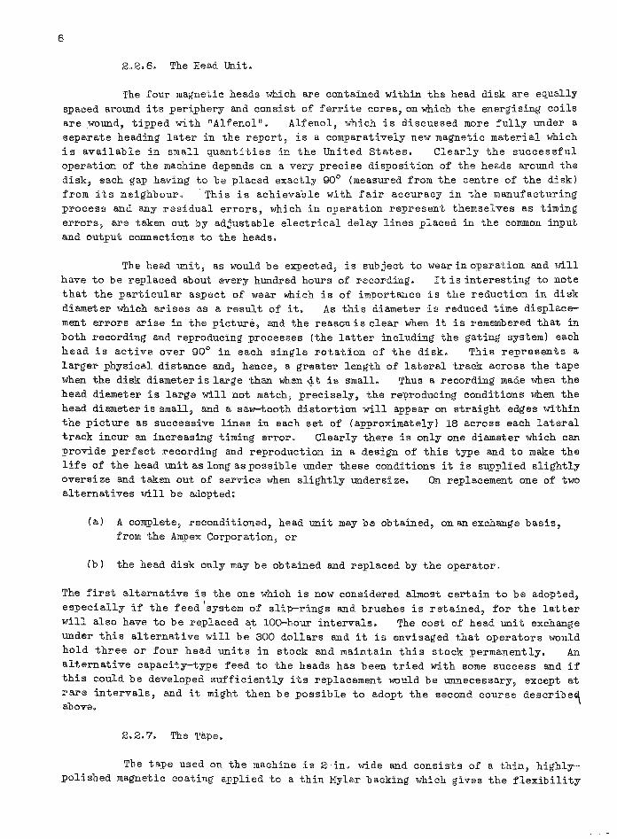
2.2.6. The Head Unit.
The four magnetic heads which are contained within the head disk are equally spaced ,around its periphery and consist of ferrite cores~ on which the energising coils are wound, tipped with "Alfenol". Alfenol, which is discussed more fully under a separate heading later in the report, is a comparatively new magnetic material which is available in small quantities in the United states. Clearly the successful operation of the machine depends on a very precise disposition of the heads around the disk, each gap having to be placed exactly 90° (measured from the centre of the disk) from its neighbour. 'This is achievable with fair accuracy in the manufacturing process and any residual errors, which in operation represent themselves as timing errors, are taken out by adjustable electrical delay lines placed in the common input and output connections to the heads.
The head unit, as would be expected, is subject to wear in operation and will have to be replaced about every hundred hours of recording. It is interesting to note that the particular aspect of wear which is of importance is the reduction in disk diameter which arises as a result of it. As this diameter is reduced time displace-ment errors arise in the picture~ and the reason is clear when it is remembered that in both recording and reproducing processes (the latter including the gating system) each head is active over 90° in each single rotation of the disk. This represents a larger physical distance and~ hence~ a greater length of lateral track across the tape when the disk diameter is large than when it is small. Thus a recording made when the head diameter is large will not match~ precisely, the reproducing conditions when the head diameter is small, and a saw-tooth distortion will appear on straight edges within the picture as successive lines in each set of (approximately) 18 across each lateral track incur an increasing timing error. Clearly there is only one diameter which can provide perfect recording and reproduction in a design of this type and to make the life of the head unit as long as possible under these conditions it is supplied slightly oversize and taken out of service when slightly undersize. alternatives will be adopted:
On replacement one of two
(a) A complete, reconditioned, head unit may be obtained, on an exchange basis, from the Ampex Corporation, or
(b) the head disk only may be obtained and replaced by the operator.
The first alternative is the one which is now considered almost certain to be adopted, especially if the feed 'system of slip-rings and brushes is retained, for the latter will also have to be replaced at lOO-hour intervals. The cost of head unit exchange under this alternative will be 300 dollars and it is envisaged that operators would hold three or four head units in stock and maintain this stock permanently. An alternative capacity-type feed to the heads has been tried with some success and if this could be developed sufficiently its replacement would be unnecessary, except at rare intervals, and it might then be possible to adopt the second course describe~ above.
2.2.7. The Tape.
The tape used on the machine is 2 in, wide and consists of a thin, highlypolished magnetic coating applied to a thin Mylar backing which gives the flexibility
7
required for correct operation in the head unit. Three manufacturers, namely, Irish Tapes, Minnesota Mining and Manufacturing Co. and Reeves Soundcraft, Inc" are, at present, successfully manufacturing tapes to the specification required; the Irish Tapes product at present giving the best results in terms of freedom from drop~outs. A standard reel of this tape used on the machine will provide one hour's recording. The life of a tape under the conditions of operation described is expected to be 100 playings. As might be expected the effect of operation is gradually to remove coating and a tape is unfit for use when the drop-outs ;created by coating removal are too numerous and severe for the frequency-modulation system to combat the poor signalto-noise ratio. The cost of a one~hour reel (1400 ft) of tape is 175 dollars. Reels of half-hour duration can be supplied at rather less than half this price, the reason being that it is easier to obtain 700 ft than 1400 ft of tape free from dropouts.
2.2.8. Editing,
It is quite possible to make joins in a tape on which recording is to take place in the machine but the cutting and the joining of tapes on which programme is already recorded, i.e. editing, is not a facility of the machine about which the manufacturers are, at present, making any claims. An operation of the latter type results in a major disturbance of the reproduced picture due to the correct phase relation between the video and synchronisation-and-control tracks suffering a discontinujty at the join. A period of time must then elapse in which the correct registration must be re-established ~ manually in the case of the· prototype machines and automatically when the automatic registration device is fi tt.ed in the production machines. It is hoped that in the automatic version the period of disturbance will not last for longer than one second and work is, at present, proceeding on a circuit to "black-out" the output of the machine until the disturbance is over and the picture is back to normal. This device is not "prpmised" for the first run of production machines. Work is also proceeding on the development of a butt-joining technique ~hich will reduce the mechanical discontinuity at the join to a minimum. The makers state that they do not envisage camera editing being possible on the machine but sequence editing may be possible when the developments described above have been accomplished. In this connection the Ampex Corporation emphasises that "the machine was designed specifically for programme delay and it is for this purpose only that it will first be employed by C.B.S. and N.B.C. to overcome the three hour East-West time difference ••• Usefulness of the ••• apparatus for other purposes awaits exploration after operation by N.B. C. and C.B. S." In concluding this discussion it is also relevant to note that, as in optical film recording, the associated sound and picture recordings are longitudinally displaced from one another,
2.2.9. Colour Recording~
All experience of the magnetic recording of the N.T.S.C. colour signal in the United States indicates that it is not feasible to make a straightforward recording of the composite signal since the phase stability required in the colour burst cannot be achieved with any reasonable, operational mechanical system. In recording the colour signal it is necessary to deal with the red, green and blue components, or with some other parameters which are related to them, separately by breaking down the composite signal before recording and reassembling it into its composite form after reproduction.. The Ampex machine will, therefore, be unsuitable in its present form
-------------------------------_ ..

8
for the recording of the colour signal and it will have to be redesigned for this purpose. The Ampex Corporation will, at present, give no indication of how they propose to adapt their system ~o colour recording but it seems clear that it can no longer be a single (video) track system so that the complexity of the rotating head unit must be increased and the tape speed also increased by some factor. No serious development work on this aspect of the recording has yet been carried out since the resources of the organisation are entirely taken up in the final development and
production of the monochrome machine.
2.3. R.C.A. Video Magnetic Recording,
203010 General.
A team under the direction of Dr. ReF. Olsen has, for some years, been engaged on the development of a video magnetic recording system at the R.C.A" Research Laboratories, Princeton, Several public demonstrations of equipment for both monochrome and colour have been given but the system has not yet been put into operational service. As far as can be ascertained no work has been carried on towards the development of a monochrome recorder, as such, for some two years and it would appear that in this field, as in some others, a rather over-optimistic appraisal of the demand for colour television (and hence colour recording) was made, resulting in what would seem to be a premature abandonment of the development of a monochrome system. The original monochrome recorder demonstrated by the RoC.A. team employed a longitudinal system operating at a speed of 360 in./sec. Since that time, however, techniques in tape and experimental head manufacture have developed to an extent that a monochrome system using a tape speed of the order of half this value and employing quarter- or half-inch tape is feasible, Another factor which would appear to have slowed up the R,CoA. development is the very rigid requirements laid down by N.BoC. covering the operation of a videc tape recorder. Broadly, they stated a requirement for a machine which would be entirely compatible with all other sources of signal, both camera and film, so that the output of the video recorder could be wiped, overlaid and inlaid in the same way as camera and film sources are now treated. Whilst this is desirable, and no doubt achievable, as a long~term objective it has tended to distort the RoC.A. development by emphasising problems concerned not so much with the fundamental aspects of recorded bandwidth and picture quality as with stability criteria in the mechanical system of the recorder. It is this situation which accounts for the extreme emphasis Which the RoC.A. have always placed on picture stability in their public pronouncements on the system and for the complicated mechanical/electrical servo-systems with which their machine bristles. Certain monochrome recording facilities which could have been provided at an early stage have, it would seem, not been made available because of the restrictions that they should only be provided in this strictly compatible form. The illogicality of this position is now revealed by N.B,C. Vs purchase of prototype Aropex video recorders which will not provide these compatible facilities and have not been designed to do so,
Itis obvious, however, that R.C.A. are continuing with their own development of the colour magnetic recording system very seriously and this includes the installation of an experimental tape manufacturing plant at Princeton for the development of improved magnetic tapes. In the N,B,C. premises in New York work is proceeding on a colour magnetic channel to bring it into operation as soon as possible. In the new television studio premises at Burbank, California j is a very large chamber, one half

9
of which is to be occupied by two channels of colour magnetic recording equipment and
the other by two channels of lenticular film recording equipment. The lenticular film
system is regarded as the next step in colour telerecording and detailed attention is
given to this in a later paragraph of the report.
2.3.2. The R.C.A. Colour Magnetic Recording System.
The R.C.A. recorder for colour signals is a six-track machine employing a
half-inch tape travelling at a speed of 240 in./sec and a schematic diagram of the
main features is shown in Fig. 3. The six tracks are occupied by a red, a green and
a blue channel (all occupying a bandwidth of H Mc/s) a "mixed-high" channel (occupying
a bandwidth of H-3 Mc/s), a synchronisation channel and a sound channel. This
division of the video bandwidth recognises the fact which research in several other
laboratories has also established, namely, that it is possible (but not easy!) to make
heads to record satisfactorily frequency bands of (o-H Mc/s) or (H-3 Mc/s), but
almost impossible to make and operate heads to record satisfactorily the single band (0-3 Mc/s). This is because the design parameters of the head cannot be chosen to
record very long and very short wavelengths with equal efficiency and in the present
state of development of tapes a compromise gives a result which is not entirely satisfactory for either range. In the
R.C.A. system no bias is employed in the
mixed-high channel, whilst in the red,
green and blue channels d.c. bias is
employed. The employment of d.c. bias
in the (O-l~ Mc/s) channels appears to be
peculiar to the R.C.A. Inour experience and, as far as can be ascertained, in
that of everyone else, there is no
advantage to be gained from it in this
application since h.f. bias of sufficient
ampli tu de and suitable frequency can
certainly be fed to a head of correct
design to record up to l~ Mc/s and the
decrease of low frequency distortion an d
noise which then results, and which is
very necessary in the video application,
has everything to recommend it. However,
the R.C.A. design of head appears to be
unique also (Section 5.4) in employing
metal, and not ferrite, cores, so that
losses at the bias frequency may be rather
higher than those to which we are accustomed. The requirement for direct
Compatibility with other programme sources is met, as noted previously, by
the introduction of various mechanical
electrical servo systems. Thus in the
recording process the main tape-drive
motor, an induction motor, also drives a tone wheel, the output of which is compared with incoming television
Tak~-tJp
spool
Fi g. 3
Tfnsion adjuster

10
synchronisation signals, to produce a constant difference signal at a constant given speed. Any variation in this difference signal, due to speed variation in the motor, alters the current fed to an eddy-current brake attached to the motor so that the speed is maintained, within limits, at the desired value. The synchronisation signals are, at the same time, recorded, together with the colour information and the sound signals. Constant tension in the tape, which is an important factor in the achievement of good speed constancy, is maintained on either side of the capstan, in both recording and reproducing, by two simple lever and idler devices which lie in contact with the tape as shown in the Figure. When the angular position of a lever alters from that which corresponds to correct tension, the rotation actuates a light-shutter and photo-cell system to vary the supply current to the feed- or take-up-spool induction motor, as the case may be. chosen, correct tension.
The torque is then adjusted to the value required for the
On reproduction the recording head which was used to record the synchronisation signals is also used as a reproducing head for these same signals and they are again compared with incoming synchronisation signals from the master synchronisation generator. The variations in the nominally constant difference signal are again applied to the eddy-current brake on the main driving motor to keep the average speed constant at its correct value. The rest of the information required is reproduced by the stack of video reproducing heads which follow the recording stack. To correct higher-frequency variations (up to about 60 c/s) which may have occurred in the recording process, or be occurring in the reproducing process, the synchronisation track is reproduced once again by a head lying in the main video-head assembly. The reproduced synchronisation signal is then compared once more with the master synchron~ sation signal (delay networks of the value required being incorporated as necessary) and the new difference signal used to alter the angular position of the whole video reproducing head assembly, which is mounted on a rotatable moving-iron mechanism of the type used in certain old-fashioned loudspeakers (Fig. 4). The complete reproducing head stack then rotates back and forth, in anti-phase to the unwanted speed changes, to keep the relative speed of the tape past the reproducing stack constant within the limits required. The lap of tape round the head is, of course, such that the gap remains in contact with the tape up to the limits of its possible movement. It is to be noted that the same comparison signal cannot be used to rotate the reproducing head stack and alter the eddy-current brake otherwise the t.,O servo-systems would "fight" one another. It is this which necessitates the use of the synchronisation recording head also in a reproducing role. It is interesting to note that the
derivation of the two difference signals is the only use made of the synchronisation signals recorded on the tape and that the reproduced picture information, obtained from
R~cord~d taplZ
Static coil
Oscilla1:ing m~mb~r
R~cordlZd tap~
.?
'six-track head
coil
Fi g. lj.
the red, green, blue and mixed-high channels, is fitted into the framework of the synchronising signals supplied from
k the master generator • This can give the picture a somewhat odd appearance when the apparatus is not in perfect adjustment. This was at first the case in a demonstration given to me, in which the picture content was moving about, in a periodic manner, inside aperfectly rigid framework of leading and trailing edges of the frame. There was also some evidence of

11
drop-outs in the recorded picture and of higher-frequency speed variations (which could not be counteracted by the servo-systems) caused, presumably, by longitudinal oscillation of the tape over the heads. The latter phenomenon is caused by the frictional excitation of the tape in passing over the head and the frequency of the oscillation which results is of the order of 2 kc/s, depending on the tape tension, the elastic properties of the tape and the coefficient of friction between the head and tape surf aces. Although not of great importance in normal audio work these oscillations are visible, if not effectively damped, in the recorded television picture where they create a sinusoidal distortion of vertical straight edges. Experience in Research Department indicates that they can be largely damped by c~rrect mechanical design of the driving system. The R. C. A. system does not include protection against drop-outs of the kind which is inherent in the Ampex system and whi6h is achieved in another way in the Bing Crosby system (q.v.). R.C.A. are, howeve~ attacking the drop-out problem by the more fundamental (and more expensive) method of investigating tape manufacture itself. Although suffering from these two faults the R.C.A. picture was in other w~s encouraging and of good entertainment value.
2.4. Bing Crosby Enterprises Colour Magnetic Recording.
2.4.1. General.
Bing Crosby Enterprises Inc. have been engaged on the development of a video magnetic recording system for about the same period as R.C.A., being originally concerned with monochrome recording but later abandoning it in order to devote their (more limited) resources to the development of a colour system. It would appear that they, too, might wish they had completed their development of the monochrome system in view of the interest which is now being expressed in the .Ampex machine. Their original system for the recording of monochrome was an 8-channel system of the time-multiplex type but some three years ago they abandoned this for two reasons Which they gave as:
(1) The complications inherent in the time-multiplex method to make it work satisfactorily When connected to a tape recording system.
(2) The application of the time-multiplex system to colour recording appeared so complicated as not to be worthy of further consideration.
They have, however, made progress in the colour recording field and they have supplied a wide-band magnetic recorder, of the type which they are developing for colour recording, to the Westinghouse Company for use in a military project on which the latter are engaged.
2.4.2. The Bing· Crosby Colour Recording System.
The Bing Crosby system is in some .rays similar to that being employed by R.C.A, but is notably simpler. The simplification derives from being less ambitious in terms of recorded bandwidth and in not incorporating any of the complicated servomechanisms which the R.C.A. consider necessary to meet the complete compatibility specification. The general quality of the picture demonstrated to me appeared to be not inferior to that demonstrated by the R.e.A. and it was, in fact, more free from

12
the effects of drop-outs. There would appear to be a good reason for the latter difference as will appear in the course of the discussion.
The system employs half-inch tape travelling at a speed of 180 in./sec using five track heads. The five tracks are devoted to red and blue channels (each occupying a bandwidth of approximately 1 Mc/s) a green channel (occupying a bandwidth of something over 2 Mc/s) a synchronisation channel and a sound channel. The difference in bandwidth between the green channel and the red and blue channels recognises the phenomenon (which was strikingly demonstrated to me at the Bell Laboratories, Murray Hill) that deterioration in the quality of a picture made up of red, green and blue primaries is almost unnoticeable when the red and blue components are defocussed (which in this context is equivalent to restriction of bandwidth) as long as the green channel retains its high definition (i.e. its full bandwidth). The recorded synchronisation signals in this system are directly employed, as such, in the subsequent reconstitution of the colour signal. To ensure efficient synchronisation-signal recording-, including freedom from amplitude modulation and drop-outs, a frequency-modulated carrier system is employed in this channel which, in fact, contains all the low-frequency information in the television picture lying below 30 kc/so Some of the same information is also carried, less efficiently, on the green (full bandwidth) track and they report no advantage in attempting to cut it out of this channel. High-frequency bias at a frequency of 7 Mc/s is employed on all the tracks.
Longi tudinal oscillation of the tape over the heads (Section 2. 3.2) is largely reduced by correct mechanical design of the drive system and any remaining oscillations of this type will be further reduced by a variable electrical delay system they claim to have perfected, which will be set to the predominant frequency of the longitudinal oscillation and arranged to operate in anti-'-phase to it. The machine demonstrated had not this latter facility fitted but they stated that it would be incorporated in their final system which is now under development. It was interesting to observe that the picture reproduced showed only small signs of this type of speed variation, which confirmed their own claims and also experience in Research Department. At one stage of development the Bing Crosby team experimented with a mechanical servo-system to overcome the longitudinal oscillation problem. This consisted of an arrangement in which a loop of the tape to be reproduced was passed over a reproducing-head system mounted on one end of a vibrating metal reed. The reed was vibrated at the amplitude and frequency necessary to take up slack in the loop in anti-phase to the speed changes caused by the longitudinal oscillation. This was abandoned because of difficulties in making the reed oscillate at the frequency required when loaded with the head.
As far as could be ascertained the heads which Bing Crosby Enterprises manufacture employ ferrite cores tipped with Alfenol and the tape in use is Minnesota IlIA tape. They have not yet attempted to change to any of the new video tapes which are now available because the use of a different type of tape alters the frequency of the longitudinal oscillation which their variable delay is designed to counteract.
In conversation they claimed to envisage some advantage in using the "crispener" technique, formerly employed by C.B.S. in their colour-sequential system, to sharpen up edges and transitions occurring in the picture and give arl apparent definition better than that suggested by the bandwidth recorded. This view might not, I believe, command universal acceptance.
X4, ....

13
3. AUDIO MAGNETIC F.ECORDING.
3.1, General.
As in other fields magnetic recording is extensively used in the United States broadcasting industry and this is especially the case in the smaller nonnetwork stations who have limited facilities for live production and limited financial resources at their disposal. I was able to visit two manufacturers of audio magneticrecording equipment, namely, The Ampex Corporation and Magnecord Inc., Chicago, who between them manufacture a wide variety of professional studio and portable equipment, home recorders, and tape gramophones. Professional equipment is also produced by the R.C.A. for broadcasting purposes and both R.C,A. and Westrex produce a large amount of professional equipment of the type used in the film and television recording industry. The Brush Company are a large producer of magnetic heads for audio applications and Brush heads are employed in various equipments manufactured by Magnecord and Westrex. The Ampex Corporation produce their own heads and have an efficient plant devoted to this part of the machine manufacture.
There is a much larger market for home recorders and magnetic tape gramophones in the United States than in this country and the price of equipment is generally smaller. A large library of recorded music tapes is available for purchase and R.C.A. Victor are making an especially big feature of this. As in the U.K. considerable interest is being displayed in stereophonic or binaural recordings and machines for the replay of such recorded tapes are being produced by the Ampex Corporation and Magnecord, Inc. I was informed by ~he Chief Engineer of Magnecord that R.C.A. intend to produce their high-quality recorded music tapes in both monaural and binaural versions.
An interesting feature of the American tape-recording industry is the wide patent coverage which appears to be held by the Armour Research Foundation of Chicago. Patents granted to them appear to cover the use of high-frequency bias in recording and various important aspects of tape manufacture. Licence fees are paid to the Armour Foundation in respect of these patents by both machine manufacturers, such as Ampex and Magnecord, and the tape manufacturers, The Minnesota Mining and Manufacturing Co. This is an extremely interesting situation since the quality of fundamental magnetic recording research being carried out by the Armour Research Foundation appeared to be well below that being carried out by such organisations as the Minnesota Company and the invention of high-frequency bias is generally attributed to Carlson and Carpenter who were not members of the Armour Research Foundation staff. Most manuf acturers admit, unoffici ally, to doubts as to whether the patent on highfrequency bias could be sustained in a court action but the licence fees called for are apparently sufficiently small to make the contesting of the patent not worthwhile.
3,2. Magnecord Inc" Chicago.
In a visit to this factory I was able to inspect various models of home, portable and professional magnetic recorders as well as machines manufactured for special purposes. The engineering management of the company has recently been completely reorganised and after various false starts they would seem to be trying to get into serious competition with Ampex in the audio field. They carry out a certain amount of contract work on cheap home recorders as a "bread and butter" source of income.
14
An interesting machine which they had in production was an eight-hour continuous reproducer of fairly conventional design employing a two-track system with 14-inch reels of half-inch tape driven at a tape speed of 7~ in./sec. The machine replays continuously through one track on the recorded tape and reverses at the end of the reel to replay the second track. A great many of these machines are being sold to restaurants and c~teens in the United States to provide continuous background music and eiilJht-hour reels of recorded music are being marketed by the R.C.A. for use with them. A broadly similar, but more compact, version cif the machine is available in which the two 14-inch reels are placed one over the other, the two shafts supporting the reels being concentric with one sleeved over the other. Compactness is the only advantage of this design for the driving capstan and spools still require three motors and there is no saving of actual equipment. One hundred such machines are being supplied under contract to one of the American railroad compan~es for the provision of background music in trains. A four-track version of the equipment is also ava~lable and is already being used on a few radio stations to supply complete programmes. Its use in the four-track version is also envisaged in frequency-modulation multiplex stations in which the transmitter is modulated by four programmes occupying appropriate bandwidths within the total frequency b and of the st ation. I was told that 'th e receiver selectivity available was such that this system had been shown. to be feasible.
In a discussion on standards with Magnecord engineers it was learned that they consider the replay equalisation for 7~ in./sec and,115>iiJ.,,/sec,.'recording shoill:d be different, more equalisation, of course, being required at the lower speed if acceptable distor~ioncharacteristics are to be obtained in production. They are of the opinion that the R. C.A. move to make the replay chain identical at both speeds is thoroughly bad and they are proposing to go on record to this effect at the next I.R.E. Convention.
3.3. The Ampex Corporation.
Professional recording machines manufactured by the Ampex Corporation in the Model 300 and Model 350 range are fairly well known. Ampex are now in quantity production on their light-weight portable recorder/reproducer, known. as the Model 600, which is claimed to have a high-fidelity performance. It is interesting to observe that to enter what is known as the "Hi-Fi" market they have also begun to manufacture an ampli:(ier/loudspeaker unit to go with the portable machine and to make both amplifier/ loudspeaker and machine units available in a fancy casing. The machine in this form is known as the Model 612. They plan a considerable expansion in this field and expect to market a'line of components including amplifiers, loudspeakers and associated items as well as complete music systems for the home. A home stereophonic system, similar in general design and appearance to the Model 612, is also in production together with the associated amplifier and loudspeaker systems. They are also manufacturing industrial music systems of the type described in the previous paragraph and theatre equipment designed for "Cinemascope" and similar types of production.
3.4. Tape Duplication.
Methods of tape duplication were discussed with various organisati0ns including The Minnesota Co., The Ampex Corporation, The Armour Research Foundation and N.B.C. Tape duplication by the method of contact printing (Research Report C-080) appears to have been dropped from serious consideration owing to the lack of suitable

master tapes • High-quality tape duplication is carried out using banks of professional recording machines all fed from Drive &
a master reproducing channel. flywheel Sets of equipment for this purpose are marketed by the Ampex Corporation and copies may be made, if required, at two or three times the normal speed by the supply of suitable tape transport and electronic systems.
Master tape
\ Rubber driving band
/
Take -up spools (copies J &2)
15
1-11--IHI-IJ---.... Drivr capstan shaft
A much cheaper and quite effective form of duplicating machine is in use in the N.B.C. studios in Chicago where it is used to provide copies, six at a time, of programmes of comment and topical interest. A diagram of the system is shown in Fig. 5. The machine is of the common-capstan type, i.e. all the tapes, master and copies,
Reproducing head
Rrcording RtZcording head htZad
are driven from the same capstan
~--------v~--------J
From ftZed spools Fi g. 5
shaft so that no additional wow and flutter is added in the copying process to that which may have occurred in the original recording. Each tape is provided with its own pressure roller, correctly positioned on the shaft, and its own recording head, which is fed with the suitably equalised output from the master reproducing channel together with the necessary h.f. bias. The feed spools are separately mounted and each rotates against a light friction brake so that tension up to the capstan is maintained within desired limits. The take-up spools are r.otated by circular rubber bands which are also driven from the common capstan shaft. Excessive tension in that portion of any tape lying between the capstan and the take-up spool causes the rubber band to slip on the shaft until the tension is restored to the safe value. The alternative to this is a slipping clutch fitted into the centre of the take-up reel but it is much more complicated and expensive and probably not much more effective unless very carefully made. As might be expected difficulty was experienced initially in finding driving belts suitable for the purpose but these are now available in quantity and the machine is reported to give very reliable service. The tape speed in the duplicating process is 45 in./sec which is three times the original recording speed of 15 in./sec. A specimen copy which was played to me at the normal speed appeared to be of entirely adequate quality for the type of programme contained in it.
3.5. Bulk Erasure of Recordings.
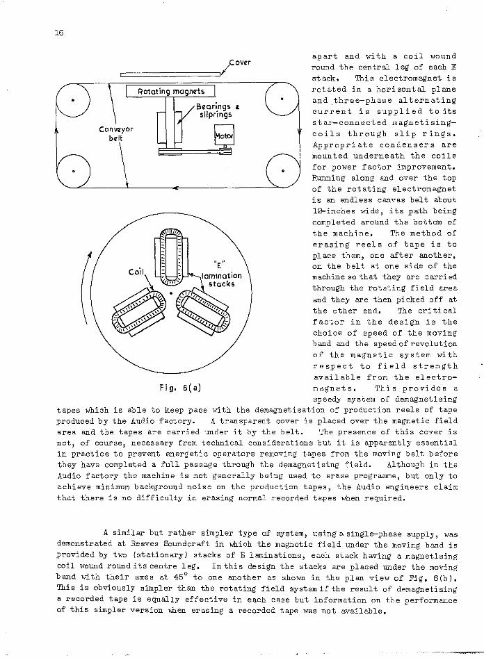
An interesting tape eraser, illustrated in Fig. 6( a), was seen in action at the factory of Audio Devices, Inc. The erasing field is supplied by three stacks of E laminations, of suitable size, mounted in a star configuration with their axes 120°
16
r:::==============:=J/C OVflr
Rotating magnets
Brarings & sllprings
apart and with a coil wound round the central leg of each E stack. This electromagnet is rotated in a horizontal plane and three-phase alternating current is supplied to its star-connected magnetisingcoils through slip rings. Appropriate condensers are mounted underneath the coils for power factor improvement. Running along and over the top of the rotating electromagnet is an endless canvas belt about l&-inches wide, its path being completed around the bottom of the machine. The method of erasing reels of tape is to place them, one after another, on the belt at one side of the machine so that they are carried through the rotating field area and they are then picked off at the other end. The cri ti cal factor in the design is the choice of speed of the moving band and the speed of revolution of the magnetic system with respect to field strength available from the electro-
Fig. 6(a) magnets. This provides a speedy system of demagnetising
tapes which is able to keep pace with the demagnetisation of production reels of tape produced by the Audio factory. A transparent cover is placed over the magnetic field area and the tapes are carried under it by the belt. The presence of this cover is not, of course, necessary from technical considerations but it is apparently essential in practice to prevent energetic operators removing tapes from the moving belt before they have completed a full passage through the demagnetising field. Although in the Audio factory the machine is not generally being used to erase programme, but only to achieve minimum background noise on the production tapes, the Audio engineers claim that there is no difficulty in erasing normal recorded tapes when required.
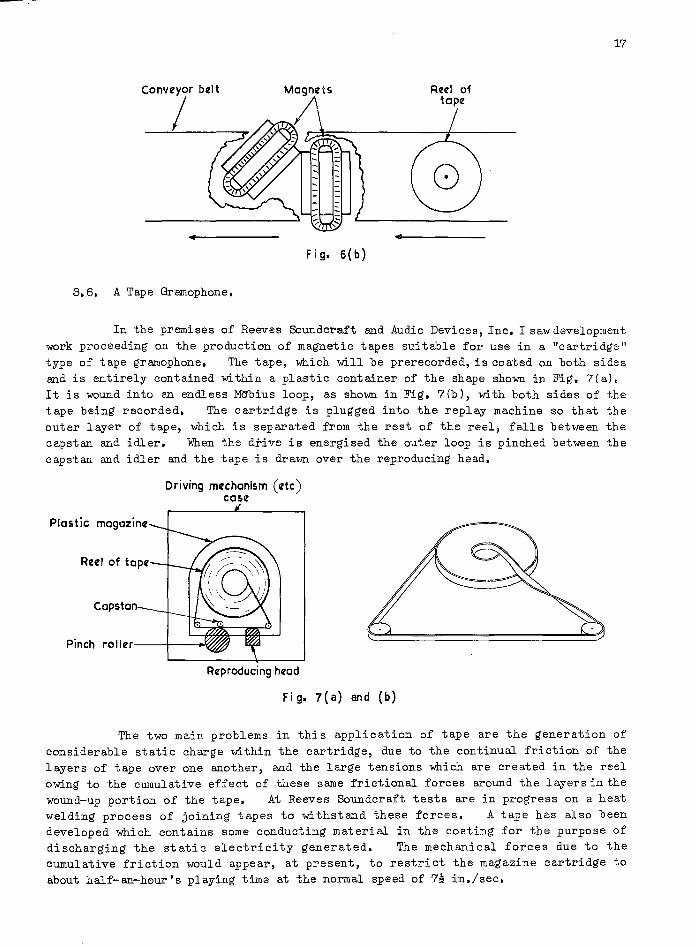
A similar but rather simpler type of system, using a singl~phase supply, was demonstrated at Reeves Soundcraft in which the magnetic field under the moving band is provided by two (stationary) stacks of E laminations, each stack having a magnetising coil wound round its centre leg. In thi s design the stacks are placed under the moving band with their axes at 45° to one another as shown in the plan view of Fig. 6(b), This is obviously simpler than the rotating field system if the result of demagnetising a recorded tape is equally effective in each case but information on the performance of this simpler version when erasing a recorded tape was not available.
• Fig. 6 (b)
3.6. A Tape Gramophone.
RIZIZJ of tape
17
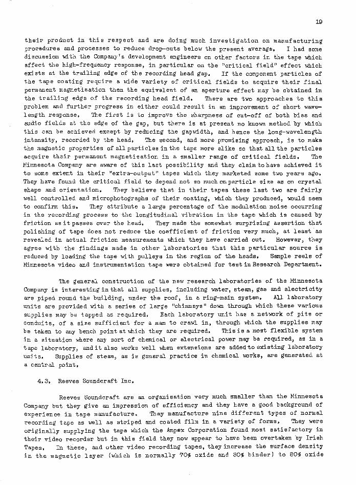
In the premises of Reeves Soundcraft and Audio Devices, Inc. I saw development work proceeding on the production of magnetic tapes sui table for use in a "cartridge 11
type of tape gramophone. The tape, which will be prerecorded, is coated on both sides and is entirely contained within a plastic container of the shape shown in Fig. 7(a). It is wound into an endless M~bius loop, as shown in Fig. 7(b), with both sides of the tape being recorded. The cartridge is plugged into the replay machine so that the outer layer of tape, which is separated from the rest of the reel, falls between the capstan and idler. When the drive is energised the outer loop is pinched between the capstan and idler and the tape is drawn over the reproducing head.
Plastic mogcz·
RuJ of t
Driving mtlchonism (fltC) co fl
Pinch rolltlr---+---o~
Reproducing heod
Fig. 7 ( a) an d (b)
The two main problems in this application of tape are the generation of considerable static charge within the cartridge, due to the continual friction of the layers of tape over one another, and the large tensions which are created in the reel owing to the cumulative effect of these same frictional forces around the layers in the wound-up portion of the tape. At Reeves Soundcraft tests are in progress on a heat welding process of joining tapes to withstand these forces. A tape has also been developed which contains some conducting material in the coating for the purpose of discharging the static electricity generated. The mechanical forces due to the cumulative friction would appear, at present, to restrict the magazine cartridge to about half-an-hour's playing time at the normal speed of 7~ in./sec.

, ' , .
i: ,
18
4. MAGNETIC TAPE MANUFACTURE IN THE U. S. A.
4.1. General,
Magnetic .recording is, at present, more widely used in the United States than in this country and the number of tape manufacturers and the variety of tapes which they manufacture is, accordingly, much greater. The largest of the tape manufacturers is The Minnesota Mining and Manufacturing Co. who manufacture the "Scotch" brand of magnetic tapes. This company has created a subsidiary in this country manufacturing "Scotch Boy" magnetic tapes but, as far as can be gathered from both organisations, development is carried on fairly independently with the larger research organisation of the parent .American company passing information to the British subsidiary as it becomes available. It is by no means surprising that independent manufacturing development is carried on by the same company in the two countries since the process of tape manufacture is still, to some extent, a matter of trial and error and only in recent years have tape manufacturers begun to make a serious scientific study of the factors which influence the final performance of their tape. The quality of the raw iron oxide, which greatly influences the final p~oduct, appears to be one of the factors least under control. It is interesting to note that in the United States the major proportion of the oxide is supplied to the industry by one chemical manufacturer. The Minnesota Company and the Irish Tapes Company are exceptional in manufacturing all their own oxide but Audio Devices Inc., the manufacturers of "Audio" tapes, have recently begun to prepare a proportion of their own oxide.
Much attention is, of course, being paid to video recording and four companies,namely, The Minnesota Co., Irish Tapes, Reeves Soundcraft and Audio Devices Inc., are, at present, manufacturing tapes which they consider suitable for video recording. The first three have each supplied 2-inch tapes to the .Ampex Corporation for use on the VR-l000 and all market i;. inch and ~-inch tapes for the more conventional approaches to this problem. The Irish tapes appear to give the best performance at present due to the lower modulation noise which they demonstrate on recording. It is interesting to observe that this company has adopted a method, in some ways akin to the early German method of tape coating, which consists of extruding the liquid oxide suspension onto the very smooth surface of a rotating drum and transferring it, partially solidified, to the prepared tape backing which is running across the top of the drum. This appears, not unexpectedly, to give the coating surface a degree of smoothness approaching that of the drum surface. The other three organisations eH/p",J.oy the more usual method in which the liquid oxide suspension is spread onto the ba:q~ing through a triangular trough with a knife-edge opening at its base" Extra smoothp.ess is obtained in this method by polishing subsequent to hardening. All companies market their branded tapes with a general guarantee that no joins exist in any reel up to 2,400' ft length and only one or two are to be expected in a 7,200 ft reel. It appears general practice to pass all tapes through a 6o-cycle A.C. eraser before
despatch to the user.
4.2. Tne Minnesota Mining and Manufacturing Co., St. Paul.
In addition to manufa.cturing tape for the Ampex Corporation the Minnesota Company are also manufacturing video tape for the R.C.A. colour video recording system. In each case the tapes are polished after manufacture. Both these varieties of tape have a very low drop-out content but the Minnesota Co. are intent on further improving
19
their product in this respect and are qoing much investigation on manufacturing procedures and processes to reduce drop-outs below the present average. I had some discussion with the Company's development engineers on other factors in the tape which affect the high-frequency response, in particular on the "critical field" effect which exists at the trailing edge of the recording head gap. If the component particles of the tape coating require a wide variety of critical fields to acquire their final permanent magnet"isation then the equivalent of an aperture effect may be obtained in the trailing edge of the recording head field. There are two approaches to this problem and further progress in either could result in an improvement of short wavelength response. The first is to improve the sharpness of cut-off of both bias and audio fields at the edge of the gap, but there is at present no known method by which this can be achieved except by reducing the gapwidth, and hence the long-wavelength intensity, recorded by the head. The second, and more promising approach, is to make the magnetic properties of all particles in the tape more alike so that all the particles acquire their permanent magnetisation in a smaller range of critical fields. The Minnesota Company are aware of thi s last possibility and they claim to have achieved it to some extent in their "extra-output" tapes which they marketed some two years ago. They have found the critical field to depend not so much on particle size as on crystal shape and orientation. They believe that in their tapes these last two are fairly well controlled and microphotographs of their coating, which they produced, would seem to confirm this. They attribute a large percentage of the modulation noise occurring in the recording process to the longitudinal vibration in the tape which is caused by friction as it passes over the head. They made the somewhat surprising assertion that polishing of tape does not reduce the coefficient of friction very much, at least as revealed in actual friction measurements which they have carried out. However, they agree with the findings made in other laboratories that this particular sour-ce is reduced by loading the tape with pulleys in the region of the heads. Sample reels of Minnesota video and instrumentation tape were obtained for test in Research Department.
The general construction of the new research laboratories of the Minnesota Company is interesting in that all supplies, including water, steam, gas and electricity are piped round the building, under the roof, in a ring-main system. All laboratory units are provided with a series of large "chimneys 11 down through which these various supplies may be tapped as required. Each laboratory unit has a network of pits or conduits, of a size sufficient for a man to crawl in, through which the supplies may be taken to any bench point at which they are required. This is a most flexible system in a situation where any sort of chemical or electrical power may be required, as in a tape laboratory, and it also works well when extensions are added to existing laboratory units. Supplies of steam, as is general practice in chemical works, are generated at a central point.
4.3. Reeves Soundcraft Inc.
Reeves Soundcraft are an organisation very much smaller than the Minnesota Company but they give an impression of efficiency and they have a good background of experience in tape manufacture. They manufacture nine different types of normal recording tape as well as striped and coated film in a variety of forms. They were originally supplying the tape which the Ampex Corporation found most satisfactory in their video recorder but in this field they now appear to have been overtaken by Irish Tapes. In these, and other video recording tapes, they increase the surface density in the magnetic layer (which is normally 70~ oxide and 30~ binder) to 80% oxide

and 20% binder, in order to increase the short-wavelength recorded level. In their manufacturing plant they have an interesting system of checking tape sensitivity immediately after the wide, uncut, coated tape emerges from the drying ovens, the value being measured both along the length and across the width from time to time. If the sensitivity falls outside a given tolerance the production run is stopped and the source of the error investigated. Reeves appear to be doing rather more work than others on the development of a cartridge tape for use in the magnetic-tape "gramophone" described in the previous section. They have also developed a system of coating optical film after printing so that a high-quality sound-track can be added after the editing process. This is, of course, much cheaper for the film maker since the editing process does not then involve wastage of expensive magnetic coating. It was interesting to observe in the manufacture of 35 mm or 16 mm film coated over the full width that the sprocket holes are punched in after coating. In this way 35 mm and 16 mm tapes were being manufactured in the same way as conventional tape by cutting up a previously coat.ed wide reel. This is obviously more convenient from the tape manufacturing point of view and enables the production cost to be reduced. In addi tion to their normal tape manufacture they have produced a tape coated with a suitable abrasive which may be used for the grinding of heads in maintenance units. Specimen reels of video, instrumentation and abrasive tape were obtained for test in Research Department.
4.4. Audio Devices Inc.
This organisation produces a variety of tapes for audio, video and computer work and also a large amount of 35 mm and 16 mm coated and striped film. The tape they produce for video purposes is known as an'''extra-precision'' tape. The extraprecision tapes are obtained by selection from the good runs in normal production and the basis of selection is a test for drop-outs using test gear of the impulse-counting type which they have developed for this purpose. Here, too, much work is being done to trace' the origin of drop-outs and some specimens of drop-outs demonstrated under the microscope included small filaments of backing, oversize magnetic particles and dust imbedded in the coating. The Audio engineers believe that the separation effect, as opposed to coating-absence, is the principle cause of signal loss in drop-outs.
5. MAGNETIC HEAD MANUFACTURE IN THE UNITED STATES.
5.1. General.
Head manufacture in the United States magnetic-recording industry has now reached a stage of great precision to meet the demands of the very widespread use of the medium in entertainment, instrumentation, telemetering and control functions. I had opportunities of discussing video head manufacture in some detail with engineers at the Brush-Clevite Development Corporation and of inspecting the manufacturing plant of the Ampex Corporation for audio and instrumentation heads. A big factor affecting the successful development of heads for high frequencies in the United States has been the availability of a comparatively new magnetic material called "Alfenol ". This is employed, in place of Mumetal, by both the Brush-Clevite and Ampex organisations as a pole-piece material attached to the ferrite cores used in high-frequency heads. It is now generally regarded as impracticable to employ ferrite cores in the magnetic head role without the use of metal pole-tips and claims made by some laboratories to the

21
contrary are now known to have been premature. Two samples of Brush high-frequency recording/reproducing heads, and a strip of Alfenol, were obtained for examination in our laboratories.
5.2. Alfenol.
When used as the pole-tip of a magnetic head Alfenol has a permeability only slightly less than Mumetal, greater resistance to work hardening, higher electrical resistance (so that high-frequency eddy-current losses are reduced) and increased resistance to abrasion by the tape. The latter property implies that it may be used, without loss of head life, in a much reduced thickness as a pole-tipping material so that the eddy-current losses are reduced even further,
The original spur to the development of Alfenol was the increasing shortage of the "strategic" material nickel which is an essential constituent of magnetic alloys such as Mumetal. It was known from very early investigations in the field of magnetic alloys that steel could also be alloyed with aluminium in certain proportions to provide high-permeability magnetic materials. Until recently, however, such alloys have not been of interest owing to the brittleness and lack of tensile strength which they appeared to demonstrate. Some four years ago this class of alloys was investigated again by the Naval Ordnance Laboratory of the United States Navy and they were able to produce an alloy, which they called "Alfenol", with favourable magnetic properties and high tensile strength. Small quantities of this material were made available to the American light engineering industry and it is from an original sample that Brush-Clevite, for ex~ple, have developed, and continue to make, their high-frequency heads.
Various industrial firms, such as the Hamilton Watch Co., have since attempted to manufacture Alfenol but their efforts have been largely unsuccessful and both the magnetic and mechanical properties of their products unpredictable •. As is well known the preparation and annealing of magnetic alloys of this type is carried out in atmospheres, such as hydrogen, which prevent oxidation of the metals. It now appears that the hydrogen atmospheres employed in the Naval Ordnance Laboratories are of a degree of purity not found in industry, a degree which is, in fact, unnecessary for the successful industrial preparo.tion of materials such as Mumetal. The (comparative) excess of oxygen in the hydrogen atmospheres of the industrial plants resulted in an Alfenol containing small, but important, fissures of aluminium oxide and having entirely different tensile properties to the original product. Various manufacturers have lost much time and money in trying to produce the material properly and the conditions necessary for its successful manufacture would now appear to make it non-competitive with nickel products. The Hamilton Watch Company have announced that they are ceasing production and the future of the alloy appears to be obscure. The original samples in the possession of organisations such as Brush-Clevite have, therefore, considerable value and it is a fortunate matter for them that high-frequency magnetic heads require so little of it. The vulnerability of the material to oxidation has, however, one redeeming feature when the alloy has once been prepared sUccessfully. In the final annealing, which can be carried out after the alloy has been machined into the shape required, a judicious degree of oxygen impurity in the annealing atmosphere has the effect of forming a thin surface layer of aluminium oxide with a hardness second only to that of diamond. It is this oxidised layer which appears to give the material its resistance to wear when in contact with the magnetic

22
tape, the surface layer being sufficiently thin to have no appreciable effect on the magnetic properties of the pole.
5.3. The Brush High-Frequency Recording/Reproducing Head.
The Brush video recording/reproducing head is similar in general design to that developed in Research Department and consists of a ferrite core which is prepared in two halves, each half being tipped with Alfenol to form the pole-piece. As a first step in the production a small, thin, lamination of Alfenol, is attached to the ferrite core, in the manner shown in Fig. 8, using an epoxy-resin of the type now generally available. The lamination is allowed to project slightly beyond one edge of the ferrite core and the faces AB and CD are ground smooth on an optical flat. One half-core is then placed in a vacuum chamber and a layer of silicon monoxide, which will form the gap spacer, is evaporated onto the face AB to a thickness roughly equal to the wavelength of green light. After the energising coils have been wound on the two halves the faces are pushed together, using a spring clamp, and the whole immersed in a sui table casting resin. The front face of the heed is then ground into a sui table arc until the Alfenol facing in the region· of the gap is some 1~ mils thick. The final shape is shown by the dotted line in Fig. 8. Since Alfenol is so very tough this 1~ mil facing still gives a reasonable life to the head with a notable reduction in eddy-current losses, the reduction being further accentuated by the higher resistivity of the material. The high-frequency performance claimed for the Brush head is superior to that which we have yet achieved and as their gap-length would appear to be of the same order as ours the difference may be attributable to the Alfenol pole-pieces.
Front" gap. Alfenol.
Fine I arc .lot grindi ng.
" ,","17r7h "
Coil. gap.
Fi g. 8
In specifying the conditions of use of their head the Brush engineers emphasise that the lap of tape over the front face should not be more than 1°, measured from the tangent across the centre of the gap, They believe that too much lap at the higher tape speeds necessary for video recording results in an air cushion forming under the tape in the region of the gap and this may, in turn, be attributable to forcing the tape to bend more sharply around the head than it is able to do, whilst still maintaining proper contact, under normal conditions of tension. The separations referred to here are, of course, an extremely minute order but they may assume importance at the wavelengths involved in recording, say, 4 Mc/s at a tape speed of 200 in,/sec.
5.4. The R.C.A. Video Recording/Reproducing Head.
The R. C.A. video head design is very different from any other high-frequency/ high-resolution head design in its employment of a magnetic-alloy core in place of the ferri te core which is otherwise generally employed. A plan view of the head structure is shown in Fig. 9 in which it will be observed that two thin laminations of Himu 80 alloy are bent together into a pear shape, the neck of the structure being held in a strong non-magnetic spring clamp. The gap of the head is formed between the two ends of the inner lamination and to finish the head the projecting laminations are ground

flush with the clamp surface to provide a smooth contact face. A coil is wound round the laminations before the bending process is carried out so as to feed the magnetising current to the core, or detect the flux changes taking place in it, as appropriate. The advantages of this construction are probably high sensitivity when low frequencies are being recorded or reproduced, a fairly long life and the possibility of making it in the small size which is requ~red in the R.C.A. multi track system. There are obvious disadvantages, however, such as the eddy-current losses which must occur in the core at high frequencies, due to its low resistivity, and the liability of the head to wear in a somewhat "vicious" fashion with a front surface made up of lamination ends lying at right angles to the tape. Another factor which might
Fig. 9
23
n-magnetic spring clamp.
prove troublesome is the occurrence of secondary-gap effects due to the presence of the magnetic discontinuities on either side of the principal gap where the two laminations composing the head are in abutment between themselves and the clamp edges. The frequency response of a specimen head shown to me during my visit to the R.C.A. Laboratories had quite obvious secondary-gap low--frequency undulations. The bad effect of these undulations in the television application is not, of course, so much in the ~agnitude of the amplitude variations as in the phase changes associated with them,
6. DISK RECORDING.
6.1, General.
Although not a prime object of the visit, information on disk recording was obtained as the opportunity arose. In particular the Capitol Records Studios, Hollywood, were inspected and a personal visit was paid to Mr. K.R. Smith, who is an expert on disk processing. The disk recording facilities in the N.B.C. Studios, Radio City, New York, and in the United Nations building were also examined in visits to these two premises. In the Capitol and N.B.C. Studios the Sculley recording lathe appeared to be the equipment generally employed but in the United Nations building the machines were less up-to-date and appeared to consist of an earlier "Presto" design.
6.2. Capitol Records Studios, Hollywood.
The Capitol Records Studios in Hollywood are situated in a new building o~ novel architectural design which is thirteen floors high and circular in shape. The outside circular wall consists almost entirely of glass windows and the lifts and other services are run up through the centre, vertical axis of the building. The advantages claimed for this design are that only 14% of the total area is needed for

24
adequate service areas (as opposed to 20% in rectangular buildings) and heating and air-conditioning are more efficient with as much as 20% less outer surface area,
The building contains three recording studios which are situated on the ground floor and basement; the largest studio occupying the height of two floors. Each studio is floated on a layer of asphalt-impregnated cork to insulate it from external vibration. Zig-zagwall panels and rotatable reflecting surfaces; consisting of birchwood on one side .and Fiberglass on the other; provide a variable acoustical environment in the studios. Three echo chambers which serve these studios are situated in a sub-basement and can be approached only by means of a trap-door and iron ladder. Sound insulation into; or out from, the echo rooms is provided by enclosing them in a "sandwich" consisting of two 9-inch layers of concrete with a 3-inch layer of cork between them.
As is general practice nowadays the master recordings of performances taking place in the studios are made on magnetic tape and the recording is transferred to disk masters as required, Disk masters) almost entirely fine-groove, are made in duplicate using two coupled Sculley lathes. The Sculley recorders are coupled in respect of automatic cutter-head lowering, the cutting of the scroll and the lifting of the recording heads. The cutter-heads employed are of a Westrex feed-back type using hot stylus aIj.d an advanced-b all mechanism. The magnetic recording machine which reproduces the master tapes to make the disk masters is provided with a monitor head which precedes the main reproducing head. The output of this head is measured, automatically, for programme level and the indication is used, in conjunction with a sui table serve-system, to increase or decrease the speed of the scrolling motors on the lathes so that the pi tch of the fine groove recordings is varied in accordance with the programme amplitude. In this way the maximum use is made of disk area and interference between adjacent grooves is avoided. The automatic system also ensures that the accommodation factor on the two master disks is identical. I learned that trouble is sometimes experienced due to accidental printing in the magnetic masters and on occasions fresh recordings have had to be made at a repeat performance, The storage area in which the master tapes are kept was noticeably cooler than the rest of the building which is generally, as is Common practice in modern office premises in the Los Angeles area, air-conditioned.
6.3, A Visit to Mr, K,R. Smith, Norwalk, Connecticut.
The object of the visit to Mr-s K.R. Smith was to ascertain the progress, if any, in a new low-pressure method of disk pressing which he had been developing and to discuss the general features of a disk processing plant and procedure which might be suitable for B.B.C. operation, if such a requirement were to ariseo It was learned from Mr, Smith that although he is confident of the eventual success of his new method he has not, due to other commitments, been able to carry out the final work required to develop it fully to an operational system. He does not, therefore, feel that it should be seriously considered in its present state of development and advises the employment of the conventional high-pressure method if a processing plant is required. If he is able, in the future, to complete his development it will be possible to replace the high-pressure moulding unit in the conventional system using vinyl by a low-pressure unit making use of geon blanks. The other principal features of the processing plant are common to both systems.
On the assumption that conventional equipment is being employed Mr. Smith recommends the use of the "master-convert" process using magnetic tape for the original

25
programme recording method and employing no "mothers", In the event of damage to the disk master the recorded tape is available for further master production. This is, of course~ the method adopted by Capitol Records, In Smith's experience the best processing results are obtained always when the recorded disk is metalled and plated immediately after recording. A lapse of time between recording and metalling almost always increases the noise level in the pressings due~ it i·s suspected, to the evaporation of castor oil and other constituents of the coating of the direct recorded disk which results in distortion of the cut surface, Any plan of operation should, therefore, envisage a reasonably quick succession of the master recording, metalling and plating process, Smith is also of the opinion that greater control over the whole production is always obtained if those responsible for the pressing operation purchase vinyl in bulk for rolling and preparation on the premises into the form required for injection into the moulds.
7, THE LENTICULAR FILM METHOD OF COLOUR TELERECORDING,
7,1. Introduction,
A system of colour telerecording employing lenticular film has been developed by R.C,A, and two channels are to be installed in the N,B.C. television studios at Burbank, California, to come into operation in September. This system will be in operational use before the colour magnetic recording system is available, on which more work is still required. A lenticular film system was attempted many years ago as a means of producing colour pictures in the cinema but it wad never successful because of the low value of light intensity it provided on the screen, which was attributable to the insertion loss of various colour filters employed in the system. This is not a drawback to the use of lenticular film in colour telerecording, however, firstly because the intensity required in the light projected through the film is less than that required in the cinema and secondly because it is possible, in this application, to dispense with colour filters altogether. Since the technical principles were described so long ago (at least in terms of television or cinema history) a brief description of the method may be of value.
7,2. Colour Separation Photography using Lenticular Film.
A diagram representing the film used in the system is shown in Fig. 10. In the production process the base of the film is embossed, by means of a suitable roller, with a series of small, cylindrical lenses, known as lenticules, which stretch across its width from one side to the other. The long axis of each lenticule is perpendicular to the edge of the film and there are about 25 lenticules to each millimetre of film length. Consider first a simple system of colour photography using lenticular film. Here the film is placed in the camera with the base towards the lens so that light entering the camera travels through the lenticules before striking the inner surface of the emulsion. Colour separation is effected by placing a four-segment colour filter in the camera lens; the two inner segments transmitting red and green and the two outer segments blue. Consideration of the geometrical optics of this, as illustrated in Fig. 11, will show that an inverted image of the light coming through the filter is formed in the emulsion at the base of each lenticule, the two outer bands in the image corresponding to blue light coming through the filter, and hence to blue components of light emanating from the scene, and the two inner bands corresponding to the green and

26
red components of the scene. The important result is that images of the three colour components of the scene have been recorded on separate areas of the emulsion, which can
Fig. 10
ObjfZct.
be of the type to give a monochrome record in each case. Similar separations will take place under every other lenticule. The reason for the use of four-segment filters, with the two outer segments transmitting the same (blue) colour, is to make fringing at the junction of lenticules unimportant because adjoining image areas formed by adjacent lenticulas then represent the same information. Colour separation by employing a filter in this way is known as the spectral separation method.
Camera lt2ns.
Colour ht=-=~f:-::.k===;:7=::~Ik!~vt7sfZparations.
E.mulsion.
Fi g. 11
The projection of the colour picture, which has been recorded in monochrome, is essentially the inverse of the recording process. The film is illuminated by a light source placed on the emulsion side and the light passing through the emulsion is projected towards the filter by the lenticules. Light from areas recorded by the red components passes through the red segment of the filter, by virtue of the inverse geometrical properties of the system, and forms a red image on the screen placed at the correct distance. Similarly light from areas recorded by the green and blue components passes through the green and blue segments of the filter to form corresponding images on the screen and the total result is an additive three-colour picture.
7.3. Colour Telerecording using Lenticular Film.
The system described in the previous paragraph is directly applicable to colour telerecording if light from three cathode-ray tubes, representing the red, green and blue components of a televised scene, is arranged to enter the camera through a colour filter in place of direct light from the visual scene. In this case although colour separation has already been performed in the television system it is necessary also to pl ace red, green and blue filters over the front of the cathode-ray tube screens

...
27
to ensure that light from each one is separately recorded, as desired, in the proper areas of the film. Some difficulties arise in this direct approach due to the insertion losses of the filters and in problems connected with the use of panchromatic film. However, as the task of colour separation has already been performed ~n the television circuit it is possible to redesign the optical system so as to make the employment of colour filters in the camera lens, or over the faces of the cathode-ray tubes, unnecessary. What is required is a geometrical arrangement which allows light from the blue channel to be directed only on to that part of the lens formerly covered by the blue segments and light from the red and green channels to be directed only onto those parts of the lens formerly covered by the red and green segments of the filter. This is known as the geometri cal method of separation and one straightforward way in which it can be accomplished is shown in Fig. 12. Here a triangular prism, having two of its faces silvered, is placed symmetrically in front of the camera lens so that it reflects light from the red and green channels into those parts of the lens previously covered by the red and green segments of the filter. Light from the blue channel proceeding past either side of the base of the prism, automatically enters the lens in those areas previously covered by the blue filter segments. Four distinct apertures are thereby created which transmit a light pattern corresponding to that formerly transmitted through the four-segment filter. This system offers the immediate advantages of greater optical efficiency, since no filters are present, and the possibili ty of using blue-sensi tive film, for the light emanating from each cathode-ray tube, although representing a different colour component of the original scene, can have the same spectral composition in all three cases.
Blue channel
Fi g. 12
In practice the optical system must be a little more complicated than the simple form shown in the Figure. It is usual to employ a lens in each of the three optical paths so that the light striking or passing the prism is collimated. The

28
two optical paths utilising the silvered faces of the prism are also brought in at angles of less than 90° to the axis of the camera lens so that the silvered prism faces lie more nearly in a plane and inter-reflections between collimators are minimised. The prism is placed at the front focus of the camera lens which is, of course, focused on infinity.
To reproduce the colour telerecording the lenticul ar film i s illuminated from the emulsion side by a suitable light source. In a system employing photomultiplier pick-ups, shown in Fig. 13, a flying spot scanner is the source and is focused on the emulsion. The light transmitted through the various separated images is automatically projected by the lenticules in bands corresponding to the apertures used in the recording system. The red and green bands are focused upon the silvered faces of a prism similar to that used in the recording system. They are then reflected in opposite directions to one another and their intensity variations amplified by the photomultipliers for assembly into the colour television signal. The two blue bands formed by each lenticule are similarly projected on either side of the prism to the face of a third photomultiplier and are assembled with the other components. The use of a continuous projector and a flying-spot scanner in this system of lenticular film reproduction eliminates colour registration problems in the transmission links of the television chain.
Flying spot scanner.
Lenticular film.
Fig. 13
Red channel.
Green channel.
omultipliers.
BlulZ channe I.
~ ------------------------------------------------------------

29
1m alternative method of reproduction employs storage tubes, such as vidicons, to produce three colour rasters. In this system, shown in Fig. 14, collimated light is directed through the lenticular film and thence, after recollimation, to the prism. Light reflected from the prism faces, in the case of the red and green channels, or passing around its base, in the case of the blue channel, is focused upon the faces of three vidicons. Each vidicon produces a raster representing its associated colour component variation and these are added to form the final signal for encoding or display, as required. In this method, of course, freedom from colour registration problems in the transmission chain is not obtained.
Fig. Jll
7.4. Discussion with Eastman-Kodak and R.e.A.
Red channel vidicon.
Green channel vidicon.
81ue channel yid icon.
The introduction of the lenticular film system into the television field has depended very much on surmounting various difficulties in the manufacture of the raw stock. For example, considerable work has been necessary to bring the focal length of the lenticular lenses on the manufactured film under control. The value achieved depends on the temperature, the pressure and the amount of solvent used in the embossing process. It has been found that best results are obtained in operation if the focal points of the lenses fall just inside the emulsion and not at the base/ emulsion interface as might be expected. Early troubles due to lack of control of this parameter have now been overcome. The specification of the actual film emulsion is also not yet finally settled and depends on the results of early operations carried
30
out by N.BoCo The uncertainty arises from a de~ree of spread which occurs within the emulsion and leads to a lack of definition. This spread can be reduced by the introduction of a yellow dye into the emulsion but the dye reduces the sensitivity of the film. A compromise between the hi~hest contrast and hi~hest definition is, therefore, necessary and this will be decided by N.B.C. as a result of experience. Once the emulsion question is settled the Eastman-Kodak factory at Rochester will be able to produce 35 mm lenticular film in quantity. The final price is not yet known but it will depend very lar~ely on the life of the rollers which are employed in the eIDbossin~ process.
Two demonstrations of lenticular-film colour recordin~ were ~iven to me at Rochester, each indicative of the results which are expected in practice. The EastmanKodak laboratory is not equipped with apparatus for makin~ telerecordin~s, as such, but it is equipped for "tele-reproduction", Le. it possesses a flyin~-spot scanner and a'photomultiplier system of the type illustrated in Fi~. 13 and the means for displayin~ the output of the photomultipliers on a television monitor.
The first demonstration of a series of the standard colour stills did, however, simulate the telerecordin~ process in some measure. To make a lenticular film slide each standard slide had been displayed on the television monitor and photo~raphed in three sta~es by placin~ a red, ~reen and blue filter in front of the monitor and makin~ the appropriate exposures. The colour apertures were produced as described in the previous para~raph. For the demonstration the lenticular slides were reproduced with the flyin~ spot scanner and the results once more displayed on the television monitor. I would describe the result as very ~ood and, as would be expected from the system, there was no si~n of colour misre~istration, The second demonstration was a reproduction of a 35 mm lenticular motion-picture film of live scenes photo~raphed with a motion picture camera. The colour separation system used in makin~ this film was, of course, of the spectral type (Section 7.2J. The film was, however, reproduced and displayed on the television monitor usin~ the ~eometrical separation method in conjunction with a continuous projector and flyin~-spot scanner. Here a~ ain the result was very satisfactory but some colour fringing was evident in out-of-focus areas, i.e. in background areas remote from the principal subject on which the motion-picture camera was focused. It is interestin~ to note that this type of colour fringing could not occur in telerecordin~ where the film camera is focused on the flat faces of the cathode-ray tubes so that out-of-focus areas do not occur. Out-of-focus areas from the television camera would not produce colour frin~in~ of this type but only a lack of definition of the normal type which is observable in the monochrome system.
In conversation with RoCoA. and N.B.C. representatives in Princeton and New York I gathered that they are ~oin~ to adopt a systemofphoto~raphin~ the ne~ative image and that they will use this record for their repeat transmissions. For distribution to non-network stations they will use Kodachrome positive prints. There is, apparently, some opposition within NeB.C. to this procedurebecauseKodachrome positives can only be produced by the Eastman-Kodak Company and time will, therefore, be lost while the ori~inal recordin~ is sent to the Eastman-Kodak factory (which does not operate durin~ the weekends) and returned. The alternative system which is bein~ advocated is to photo~raph the positive ima~e in the ori~inal recordin~ and then make Eastman-Colour prints for distribution to non-networks stations. Eastman-Colour prints are made usin~ a subtractive dye process and the duplicates could be produced by NeB.Co themselves which would avoid the time lost whilst the original is in transit to and from the Eastman-Kodak factory at Rochester.

: ,
31
8. OPTICAL FILM EDITING USING TELEVISION AND RECORDING TECHNIQUES.
A novel system of film editing, which effects great economies in edi ting time, has been developed by WaIt Disney Studios, Hollywood, in conjunction with the Westrex Corporation. This employs a new design of film editing _machine which is very compact and convenient to operate and which has recently been marketed by Westrex. When using the machine in its standard form the operator sits in front of a console and both the optical film and the synchronised magnetic sound-film, which have been previously recorded, are driven through a composite head unit in the machine. A light system is used to project the optical film onto a ground glass screen in the front of the console and the sound-track is reproduced through a loudspeaker in the normal manner. The operator can, at will, vary the speed of running between stop and full speed and is able to mark or cut and join as required.
In the WaIt Disney development three of these editing machines have been incorporated to provide, if required, a three-camera editing system with automatic editing instructions. A schematic diagram of the system is shown in Fig. 15. The three Westrex editing machines are situated side by side and are coupled together
Editing
Machine1
Optical film 1
Mu It it rack rnstruc,tion
tape.
w u
Glass partition.
Edit ing
Machine 2
Magnetic sou n d (al ternat ives).
Fi g. 15
6:)
Editing
Machine 3
32
electrically so that the optical and magnetic films in all three are in synchronisation. The normal optical system in each machine, which projects the image onto the ground glass screen, is in this application replaced by a television film scanning system so that an image of the film appears instead on a particular television monitor in the adjoining cubicle. When the system is set in motion images from the three editing machines then appear continuously on three such monitors. Above the three primary monitors is a large main monitor and anyone of the three primary images can be selected, using a push-button control, to appear also on this monitor. The normal magnetic sound system of one machine (say number one) is now replaced by a multi track magnetic-head system (in the equipment demonstrated six tracks were provided but only three used) which may, for the purpose of description, be referred to as the magneticinstruction system. Either of the other two magnetic channels (say on machines 2 and 3) is available for replaying the sound track relating to the film to be edited. The action, previously described, of s.li tching the image from one editing machine also onto the main monitor effects a simultaneous tone recording on a related track in the instruction system, the tone being recorded for as long as the image from that particular machine is appearing on the main monitor. It can be assumed th~t the film sequences in the three editing machines are related close-up or medium or atmosphere takes relating to the same incident or situation in the scenario. The editor works in the cubicle containing the television monitors and has remote control of the three synchronised editing machines. He then selects, using the push-button control, whichever image he wishes to appear on the main monitor. As long as image 2, for example, is on the main monitor a tone is recorded on magnetic track 2 of the instruction system. When the editor decides that a shot from, say, machine 1, should follow in the edited sequence he presses the relevant button to bring the image on monitor 1 onto the main monitor and this simultaneously stops the recording of tone on instruction track 2 and transfers it to instruction track 1. He may stop the whole system, wind back and re-edit, if he wishes to change his mind or try an alternative sequence. Any changes which he introduces in this way automatically erase the previous instructions relating to the parts re-edited. When he has completel~ edited, or selected from, the three reels in this manner he is left with an instructiop. tape which contains tones recorded on three instruction tracks each corresponding to a camera sequence which he decided should appear in the final version. The whole system may then be rewound and directly replayed. The instruction tones on the tape then serve the purpose of switching the images from machines 1, 2 or 3 into the main monitor exactly in accordance with the recorded instructions. A preview of the complete edited sequence is then available before any cutting or joining has been carried out on the original takes. When the editing is finally approved the optical films, the sound tape and the instruction tape are sent to the editing department and resynchronised. The beginnings and endings of tone on the instruction tracks serve as the cue marks which indicate how the relevant optical films should be cut ar;. d assembled. It is claimed that when using this system the time required for editing is reduced by a factor of 10 to 1.
9. TELEVISION OVER TELEPHONE LINES.
An interesting development whi.ch is nearing completion in the Bell Telephone Laboratories is a method of transmitting picture information over telephone lines, in a bandwidth of 1200 cis, so that ne.T complete frames are presented at the other end of the line at two second intervals, It is hoped to sell this as an adjunct to the

33
personal telephone service but it is obvious that it might have application for quick, lower-quality picture transmission in, say, a News Service.
To originate the picture a small Iconoscope camera has been modified to give a sixty-line picture, each line containing forty horizontal elements, in a twentieth of a second once every two seconds. The scanning information is recorded, line by line, on the periphery of a small magnetic drum which is running synchronously with the camera at a rate of twenty times per second. Figure 16 shows diagrammatically the way in which picture element information is laid down around the drum. Each line contains 40 elements which may be numbered 1, 2, 3, etc. During the twentieth of a second in which the 2,400 picture elements are being recorded on the drum a parallel gating circuit operates 60 times so that all picture elements 1proceed also direct to line to be dealt with at the receiving end in a manner to be described. In the time remaining before the next frame is supplied by the camera (i.e. in the remaining 39/20 seconds) the gating circuit continues to operate in the same manner but now taking signals reproduced from the drum so that all picture elements 2 are made available followed by all picture elements 3 and so on. This continues until all picture elements 40 have been despatched after which the new frame from the camera is available and the new picture elements 1 are sent to line as before followed by picture elements 2 from the
Lint I Lint 2 Lint 3 f .~r
11\\~' ,1l~;\ ill'" I 35
Elfmfnts I 3
2 4 b 24 b 2
Fi g. 16
drum, etc. Simple calculation will show that the bandwidth required to transmit the information is 1200 c/s.
At the receiving end of the telephone line two methods are available for presenting the picture, one being a duplicate of the magneticdrum system by which the line signal was originated and the other a storage-tube system. In the first the 2,400 el ement s arriving at the receiving end in each two-second period are recorded on another drum and then reproduced in a twentieth of a second through a gating circuit, which operates only for this period, for display on a small television monitor of appropriate design. Thus complete (sample) pictures are available at intervals of two seconds. In the storage-tube method the two-second information patterns coming up the line are l~id down al ternately on two Farnsworth "Iotron" tubes. This design of tube has the property of holding a charge pattern providing that no H.T. voltage is applied to the tube. When a complete frame has
Lint 4 .~ rte
'I\" " I
ete I 3
2
ObsrrvlZr
Fi g. 17
34
been laid down on the first Iotron an HoT, voltage is applied so that the picture becomes visible and is held for two seconds, after which the tube is flashed to clear it. Meanwhile the picture information coming up the line in the second period of two seconds (in which the first Iotron is displayed) is recorded on the second Iotron and H.T. is applied to this tube at the moment when the first tube is cleared. In practice the two tubes are placed at right angles to one another and a half-silvered mirror is located between them making an angle of 45° to each of their axes, as shown in Fig. 17. The viewer looking in the front of the magic box then has a continuous picture presented to him. The problem of registration of the two tubes to give satisfactory overlay has not been found to be serious. It is interesting to note in the Iotron method of display, which has just been described, that the use of the sampling method to reproduce the information stored on the drum at the originating end of the line transforms the scanning from horizontal to vertical, for all picture elements 1 arrive first, then elements 2, etc. It is, therefore, advantageous to turn the Iotrons through 90° from the position they would normally occupy, i.e. to turn them on their "side if, When the drum and monitor system is employed at the receiving end this phenomenon is not present, of course, for the second recording and gating process results in picture-element information arriving in the same order as that provided by the camera.
10. MISCELLANEOUS ITEMS.
10.1. Television Studios.
Visits were made to the N.B.C. Television Studios in Chicago and Burbank, California, and also to the C.B.S. Studios in Hollywood. These were very largely of educational benefit to me and I would not presume that the observations made on these occasions were necessarily original or that the information gained is "hot" news, but some general points are set down in the hope that they may, at least, be interesting.
The N .B. C. studios in Chicago have recently been reorganised and re-engineered to produce colour televi sion programmes entirely. Al though all work is not yet complete they are in operation producing about two or three hours of colour programme per day. These are mostly of comparatively modest nature, the large colour "spectaculars" originating from New York and Hollywood in alternate months. It was interesting to observe that some programmes were being produced in full colour using colour cameras but were intended only for monochrome network distribution. Inthese cases the colour signal is "killed" in the control room and the normal monochrome signal is transmitted as, I was informed, the networks insist on a normal monochrome signal and will not accept the N.T.S.C. composite signal for transmission as a monochrome signal. It has been found that the cameras and associated studio equipment have to be lined up and registered just as accurately when the colour signal is to be ''killed'' as when it is to be seriously transmitted. None of the studios in Chicago is large and, together with the film reproducing facilities, they are all situated on one floor of the Market Exchange building. There is a single master control room in which the output of all the studios is monitored and adjusted before transmission. The film transmission studio is actually adjacent to one of the smaller live studios in which simple sponsored colour programmes are originated. The "commercials" associated with these programmes are also, in many cases, fairly simple and consist of colour slides with live commentary. For slide transmission there is a form of turret mounting on which

35
a series of twenty slides can be mounted before transmission and turned into the slide scanning field as required. In the arrangements which have been adopted it is' possible for any slide in the turret to be viewed also by the camera in the adjacent studio through an opening in the party wall, making it unnecessary to completely man the film studio and scanning equipment during times when motion picture scanning is not required. The camera in the studio then fulfils both "live" and slide functions.
The N.B,C. television studios in Hollywood and Burbank are extremely extensive with monochrome programmes originating in the Hollywood premises and the Eurbank studios being devoted entirely to colour. The master control which is still in the Hollywood premises is shortly to be transferred to Eurbank. The film equipment at Burbank includes full facilities for normal film transmission in either colour or monochrome, together with space for two lenticular film systems and for two video-tape colour channels. The Eurb ank studios are built on a tremendous scale and in some studios the height is such that experiments are being carried out in the "flying" of television scenery. In both Chicago and Burbank, as well as in the C.E.S. studios in Hollywood, it was interesting to learn that direct visual observation of the television studio from the control cubicle is no longer considered an important requirement. In the new C.B.S. studios in Hollywood, in fact, only four control cubicles are associated with the six studios. Although in the older premises in Chicago individual control cubicles, at studio floor level, are still associated with each studio, direct observation is usually completely obscured by the presence of scenery and the system will eventually be completely flexible allowing any studio to be operated from any control room.
In examining general questions of television serviceability, as apparent to the viewer, two observations made in the N.E.C. premises may be of interest:
(1) Owing to the requirements imposedby the time difference existing between the East and West coasts, a very considerable percentage of programme is prerecorded on film. A generous duplication of facilities is provided to avoid breakdowns in the subsequent transmission. Thus telerecordings are made on both 35 mm and 16 mm channels, each having an optical sound-track associated with them, and also a high-quality magnetic sound-track is recorded at the same time on a separate magnetic recorder. On transmission the 35 mm recording is used in conjunction with the synchronised magnetic sound track, Should a fault develop the reserve picture channel or ei ther one of the optical sound channels is immediately switched in as required.
(2) A multi-camera "live" programme is never stopped as a result of a breakdown in one camera. When such abreakdown occurs improvised arrangements aremadeimmediately to complete the transmission on the basis of the remaining serviceable cameras. This was stated to be the practice even when a performance was being given purely for telerecording, when it is customary to proceed with the programme and bring the faulty camera into operation again as soon as it is serviceable. Shots which are deemed to be unsatisfactory as a result of this are sometimes repeated at the end of the performance and edited into the full recording as required.
The above practices are stated to be imperative to hold the tight schedule of programmes dictated by advertising and networking arrangements and a producer stopping the show in circumstances when improvisation is possible is considered to have little future in the profession.

36
10.2. The Universal Zoomar Lens.
In a visit to the scene of an outside broadcast at Madison Square Garden~ New York~ I had an opportunity of looking at the picture produced by the Universal Zoomar Lens~ a specimen of which is being used by the N.B.C. in appropriate programmes. Later I was able to discuss the lens in general terms with the designer. The Universal Zoomar Lens has an aperture variable between f.4 and f.45 and at f.5.6 it produces a resolution equal to 600 television lines over the entire range of focal length from 2 - 16 inches. The lens is corrected for chromatic observa~~on on both lateral and longitudinal axes and it is~ therefore, suitable for both colour and monochrome transmissions. The distance range which the lens is capable of viewing is from 15 ft to infinity., It weighs 10 lbs and is priced at 8,500 dollars. Because of its light weight it can be mounted on a normal camera turret without support but this does not indicate~ necessarily~ that other lenses can be used on the turret in conjunction with it. In fact the Zoomar lens would appreciably obstruct the field of view of all except very narrow-angled lenses. The designer emphasised that the lens is unsuitable for use with the Marconi Mark III camera since the manual control by which the lens is operated cannot be brought through the centre of this camera owing to the layout of the electronic gear within it. The manual control takes the form of a single rod which the operator pushes in and pulls out to achieve the "zoom" facility. The lens actually in use at present by N .B. C. is a second specimen, the first having been returned to the factory for examination. The designer emphasised that this was to provide technical information to him on the effect of operations and not because of any shortcomings which had developed in service. The camera operators I spoke to consider the lens to have a performance equal to that provided by the lower range of the Watson Zoom lens although the Zoomar image is "possibly a little softer around the edges". They stated that they found the lens easy to use.
11. CONCLUSION.
In conclusion I wish to express my thanks to the New York Representative and his staff? and especially to the :ill.LC. Ne'; York, Mr. A.S.R. Toby, for all the valuable assistance and advice which contributed materially to the smooth working of arrangements for my tour and to the correct choice of contacts in the organisations visited.

APPENDIX
ORGANISATIONS AND PREMISES VISITED
(1) N.B.C. Studios and Radio City, New York.
(2) NoB.C. Television Outside Broadcast Unit at Madison Square Garden.
(3) United Nations Communications Section, United Nations Building, New York.
(4) R.C.A. Laboratories, Princ et on , New Jersey.
(5) Bell Telephone Laboratories, Murray Hill, New Jersey.
(6) Reeves Soundcraft Inc., New York and Stamford, Connecticut.
(7) Audio Devices, Inc., Stamford, Connecticut.
(8) Mr. K.R. Smith, Electroform Corporation, Norwalk, Connecticut.
(9) The National Bureau of Standards, Washington.
(10) The Eastman-Kodak Factory and Research Department, Rochester.
(11) The General Electric Oompanyis Research Department, Electronic Park, Syracuse.
(12) The Massachusetts Institute of Technology, Cambridge, Mass.
(13) The Brush-Clevite Development Corporation, Cleveland, Ohio.
(14) The Minnesota Mining and Manufacturing Co., St. Paul, Minnesota.
(15) NoB.C. Studios, Chicago.
(16) Magnecord Inc., Chicago.
(17) The Armour Research Foundation, Chicago.
(18) The Aropex Corporation, Redwood City, California.
(19) The Westrex Corporation, Hollywood.
(20) Bing Crosby Enterprises, Inc" Hollywood.
(21) WaIt Disney Studios, Burbank, California.
(22) N.B.C. Studios, Hollywood.
(23) N.B.C. Studios, Burbank, California.
37
38
(24) CoBoS. Studios, Hollywood.
(25) N.BoCo Television Transmitter Station, Mount Wilson, California,
(26) The Bell Telephone Companyis Television Link Station, Mount Wilson, California.
(27) The Glenn Recording Studios, Hollywood.
(28) The Capitol Records Studios, Hollywood.
MM EGF
Printed by B.B.C. Research Department, Kingswood Warren, Tadworth, Surrey


![Let's grow South Africa together - Riotous Assemblies Act...UNION GAZETTE EXTRAORDINARY, 16TH MARCH, 1956. 33 No. 17, 1956.] ACT To consolidate the laws relating to riotous assemblies](https://static.fdocuments.us/doc/165x107/5fec07891b6870562e721d08/lets-grow-south-africa-together-riotous-assemblies-act-union-gazette-extraordinary.jpg)


![Clark E. & Tunaru R. [2005] the Evolution of Political Risk 1956 - 2001](https://static.fdocuments.us/doc/165x107/550209764a795971028b4c4a/clark-e-tunaru-r-2005-the-evolution-of-political-risk-1956-2001.jpg)