
RAK439 Porting Manual · RAK439 Porting Manual RAK439 Porting Manual Shenzhen Rakwireless...
37
RAK439 Porting Manual RAK439 Porting Manual Shenzhen Rakwireless Technology Co.,Ltd www.rakwireless.com Email: [email protected]
Transcript of RAK439 Porting Manual · RAK439 Porting Manual RAK439 Porting Manual Shenzhen Rakwireless...
RAK439 Porting Manual
RAK439 Porting Manual
Shenzhen Rakwireless Technology Co.,Ltd
www.rakwireless.com
Email: [email protected]
RAK439 Porting Manual
Content 1. Hardware Platform Resources ............................................................................................... - 1 -
2. Driver Library Parameters ..................................................................................................... - 1 -
2.1 Indroduction of Driver Library Parameters ................................................................ - 1 -
2.2 Platform Dependent Interface ................................................................................... - 2 -
2.2.1. hw_init........................................................................................................... - 2 -
2.2.2. hw_deinit ...................................................................................................... - 3 -
2.2.3. hw_power ..................................................................................................... - 3 -
2.2.4. driver_malloc ................................................................................................ - 3 -
2.2.5. driver_free ..................................................................................................... - 4 -
2.2.6. time_delay ..................................................................................................... - 4 -
2.2.7. Stamp_get ..................................................................................................... - 4 -
2.2.8. toggle_irq ...................................................................................................... - 4 -
2.2.9. spi_io_buffer ................................................................................................. - 5 -
2.2.10. driver_assert ................................................................................................. - 5 -
2.3 Application Callback Interface .................................................................................... - 5 -
2.3.1. conn_cb ......................................................................................................... - 6 -
2.3.2. scan_cb .......................................................................................................... - 6 -
2.3.3. easy_wps_cb ................................................................................................. - 7 -
2.3.4. dhcp_cb ......................................................................................................... - 7 -
2.3.5. dns_cb ........................................................................................................... - 7 -
3. Introduction of Driver Library OS Interface ........................................................................... - 8 -
3.1 Task Interface ............................................................................................................. - 8 -
3.1.1. rw_creat_task ................................................................................................ - 8 -
3.1.2. rw_del_task ................................................................................................... - 8 -
3.2 Mutex Interface .......................................................................................................... - 8 -
3.2.1. rw_creat_mutex ............................................................................................ - 8 -
3.2.2. rw_del_mutex ............................................................................................... - 9 -
3.2.3. rw_lock_mutex .............................................................................................. - 9 -
3.2.4. rw_unlock_mutex .......................................................................................... - 9 -
3.3 Semaphore Interface ................................................................................................ - 10 -
3.3.1. rw_creat_sem ..............................................................................................- 10 -
3.3.2. rw_del_sem .................................................................................................- 10 -
3.3.3. rw_post_sem ...............................................................................................- 10 -
3.3.4. rw_pend_sem .............................................................................................- 11 -
4. RAK439 SPI Interface ...........................................................................................................- 11 -
5. RAK439 External Interrupt ..................................................................................................- 13 -
6. STM32F4 Platform Porting Example....................................................................................- 13 -
6.1 Software Package Introduction ................................................................................ - 13 -
6.2 Porting Steps in Non-OS ........................................................................................... - 14 -
6.2.1. hw_init Implementation ..............................................................................- 16 -
6.2.2. spi_io_buffer Implementation ....................................................................- 19 -
RAK439 Porting Manual
6.2.3. toggle_irq Implementation ......................................................................... - 20 -
6.2.4. hw_power Implementation ......................................................................... - 20 -
6.2.5. hw_deinit Implementation ..........................................................................- 21 -
6.3 Non-OS Program Introduction.................................................................................. - 21 -
6.3.1. Example Introduction of AP & STA Networking:..........................................- 22 -
6.3.2. Example of A key configuration: ..................................................................- 23 -
6.3.3. Introduction of Socket Communication Example ........................................ - 26 -
6.4 Porting Steps in OS ....................................................................................................- 27 -
6.4.1. rw_creat_task Implementation ...................................................................- 28 -
6.4.2. rw_del_task Implementation ......................................................................- 28 -
6.4.3. rw_creat_mutex Implementation ...............................................................- 28 -
6.4.4. rw_del_mutex .............................................................................................- 29 -
6.4.5. rw_lock_mutex Implementation .................................................................- 29 -
6.4.6. rw_unlock_mutex Implementation .............................................................- 29 -
6.4.7. rw_creat_sem Implementation ...................................................................- 30 -
6.4.8. rw_del_sem Implementation ......................................................................- 30 -
6.4.9. rw_post_sem Implementation ....................................................................- 30 -
6.4.10. rw_pend_sem Implemenation ....................................................................- 30 -
6.5 OS Program Introduction.......................................................................................... - 31 -
6.5.1. Example Introduction of AP & STA Networking:..........................................- 31 -
6.5.2. Example of A key configuration: ..................................................................- 31 -
6.5.3. Introduction of Socket Communication Example ........................................- 31 -
7. Sales and Service .................................................................................................................- 33 -
8. Revision History ...................................................................................................................- 34 -
- 1 -
RAK439 Porting Manual
1. Hardware Platform Resources
The required resources of MCU peripheral are as follows:
one SPI Interface
one external interrupt pin
one reset module pin
one control module power switch pin (optional)
one upward counter to handle time-out of internal driver
The memory of RAK439 driver library without OS are occupied as below:
Flash takes up about 35K bytes
RAM
Global variables, static variables: 740 bytes
Stack: allocate at least 4K bytes (one RX buffer, one socket buffer, four scan buffers)
2. Driver Library Parameters
2.1 Indroduction of Driver Library Parameters
typedef struct
{
bool spi_int_enable; // customer can choose enable or disenable spi int event
// driver
uint8_t rx_queue_num; // rx buffer queue num >= 1
uint8_t socket_max_num; // module support socket numbers max 8
uint8_t scan_max_num; // scan result buffer numbers normal : 10 if you need more
// can raise it
uint8_t tcp_retry_num; // tcp backoff retry numbers
char* host_name; // module host name ,you can see it in router clients when
// DHCP success
char* country_code; // set module country code ,CN (1-13),JS(1-14),UP(1-11)
struct driver_cb_ driver_cb; // platform related driver used
struct app_cb_ app_cb; // application related callback info
}rw_DriverParams_t;
Parameter Description:
spi_int_enable:when not use os, if set spi_int_enable true, present the module have enabled
the external irq, so mcu must connect to the module’s irq pin; if set spi_int_enable false,
present the module have disabled the external irq, so mcu must not connect to the module’s
- 2 -
RAK439 Porting Manual
irq pin. When use os, the module use external irq pin forcibly.
rx_queue_num: number of RX buffer >= 1, one RX buffer is 1664 bytes, driver allocates
memory from heap when RAK439 load drivers (execute rw_sysDriverInit) , release memory
when uninstall the drivers (execute rw_sysDriverDeinit).
socket_max_num: number of socket, maximum is 8, one socket buffer is 48 bytes, driver
allocates memory from heap when RAK439 load drivers (execute rw_sysDriverInit) , release
memory when uninstall the drivers (execute rw_sysDriverDeinit).
scan_max_num: the number of scanned buffer, at least four. One scan buffer is 44 bytes, in
STA mode, when RAK439 is connecting to the router (execute rw_wlanConnect) driver will
allocate memory from heap, and release memory after connection; when user application
scans (execute rw_wlanNetworkScan), driver will allocate memory from heap, but does not
release memory, so users need to manually release the memory after the scaninfo is useless.
tcp_retry_num:tcp retransmission max time interval is 2tcp_retry_num+1
s。
host_name: after DHCP , the hostname displayed in router client list
country_code: module country code, CN (1-13),JP(1-14),US(1-11)
driver_cb: platform dependent interface
app_cb: application callback interface
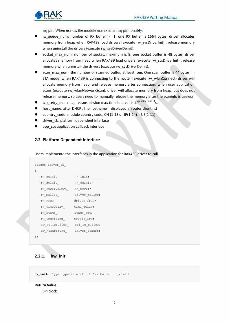
2.2 Platform Dependent Interface
Users implemente the interfaces in the application for RAK439 driver to call
struct driver_cb_
{
rw_HwInit_ hw_init;
rw_HwInit_ hw_deinit;
rw_PowerUpDown_ hw_power;
rw_Malloc_ driver_malloc;
rw_Free_ driver_free;
rw_TimeDelay_ time_delay;
rw_Stamp_ Stamp_get;
rw_ToggleIrq_ toggle_irq;
rw_SpiIoBuffer_ spi_io_buffer;
rw_AssertFunc_ driver_assert;
};
2.2.1. hw_init
hw_init Type typedef uint32_t(*rw_HwInit_)( void )
Return Value
SPI clock
- 3 -
RAK439 Porting Manual
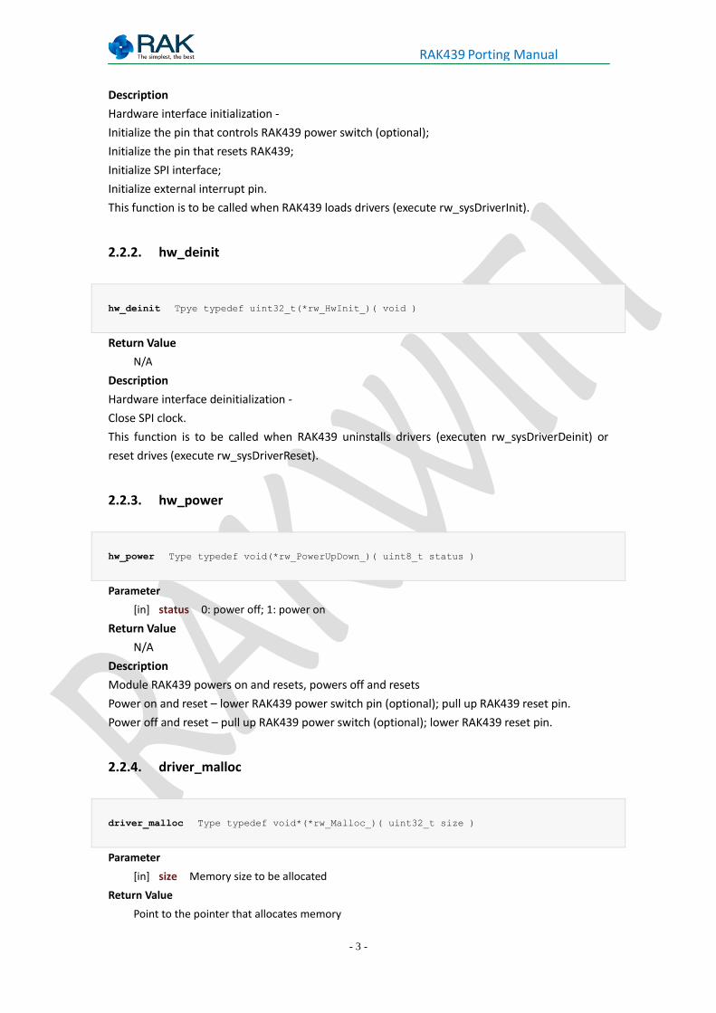
Description
Hardware interface initialization -
Initialize the pin that controls RAK439 power switch (optional);
Initialize the pin that resets RAK439;
Initialize SPI interface;
Initialize external interrupt pin.
This function is to be called when RAK439 loads drivers (execute rw_sysDriverInit).
2.2.2. hw_deinit
hw_deinit Tpye typedef uint32_t(*rw_HwInit_)( void )
Return Value
N/A
Description
Hardware interface deinitialization -
Close SPI clock.
This function is to be called when RAK439 uninstalls drivers (executen rw_sysDriverDeinit) or
reset drives (execute rw_sysDriverReset).
2.2.3. hw_power
hw_power Type typedef void(*rw_PowerUpDown_)( uint8_t status )
Parameter
[in] status 0: power off; 1: power on
Return Value
N/A
Description
Module RAK439 powers on and resets, powers off and resets
Power on and reset – lower RAK439 power switch pin (optional); pull up RAK439 reset pin.
Power off and reset – pull up RAK439 power switch (optional); lower RAK439 reset pin.
2.2.4. driver_malloc
driver_malloc Type typedef void*(*rw_Malloc_)( uint32_t size )
Parameter
[in] size Memory size to be allocated
Return Value
Point to the pointer that allocates memory
- 4 -
RAK439 Porting Manual
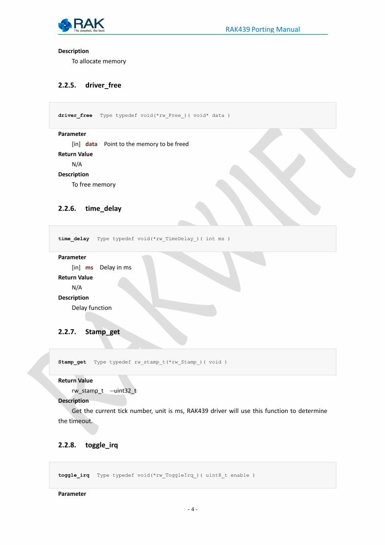
Description
To allocate memory
2.2.5. driver_free
driver_free Type typedef void(*rw_Free_)( void* data )
Parameter
[in] data Point to the memory to be freed
Return Value
N/A
Description
To free memory
2.2.6. time_delay
time_delay Type typedef void(*rw_TimeDelay_)( int ms )
Parameter
[in] ms Delay in ms
Return Value
N/A
Description
Delay function
2.2.7. Stamp_get
Stamp_get Type typedef rw_stamp_t(*rw_Stamp_)( void )
Return Value
rw_stamp_t --uint32_t
Description
Get the current tick number, unit is ms, RAK439 driver will use this function to determine
the timeout.
2.2.8. toggle_irq
toggle_irq Type typedef void(*rw_ToggleIrq_)( uint8_t enable )
Parameter
- 5 -
RAK439 Porting Manual
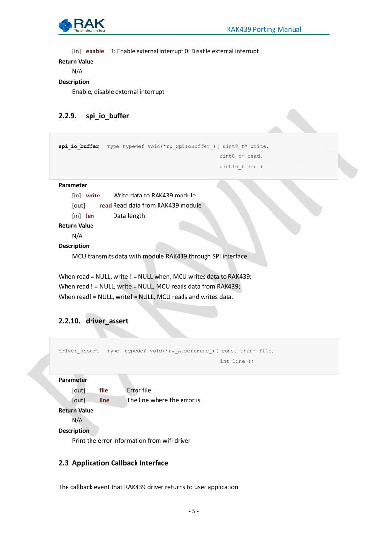
[in] enable 1: Enable external interrupt 0: Disable external interrupt
Return Value
N/A
Description
Enable, disable external interrupt
2.2.9. spi_io_buffer
spi_io_buffer Type typedef void(*rw_SpiIoBuffer_)( uint8_t* write,
uint8_t* read,
uint16_t len )
Parameter
[in] write Write data to RAK439 module
[out] read Read data from RAK439 module
[in] len Data length
Return Value
N/A
Description
MCU transmits data with module RAK439 through SPI interface
When read = NULL, write ! = NULL when, MCU writes data to RAK439;
When read ! = NULL, write = NULL, MCU reads data from RAK439;
When read! = NULL, write! = NULL, MCU reads and writes data.
2.2.10. driver_assert
driver_assert Type typedef void(*rw_AssertFunc_)( const char* file,
int line );
Parameter
[out] file Error file
[out] line The line where the error is
Return Value
N/A
Description
Print the error information from wifi driver
2.3 Application Callback Interface
The callback event that RAK439 driver returns to user application
- 6 -
RAK439 Porting Manual
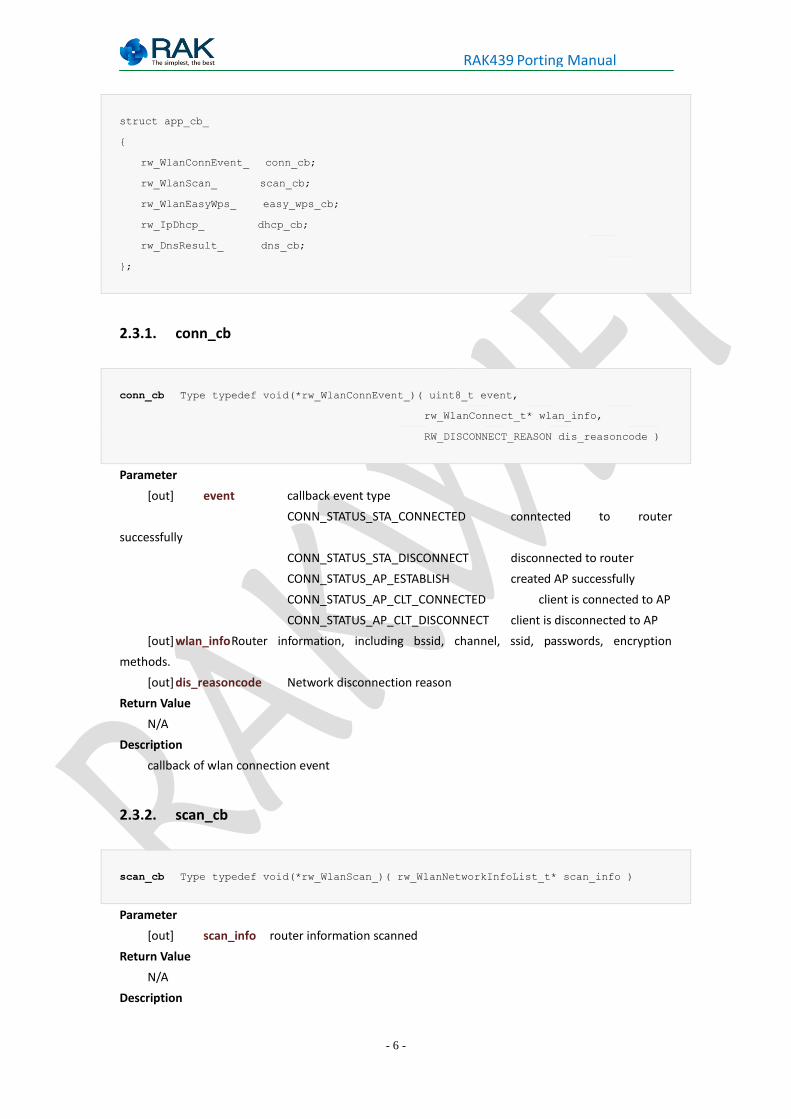
struct app_cb_
{
rw_WlanConnEvent_ conn_cb;
rw_WlanScan_ scan_cb;
rw_WlanEasyWps_ easy_wps_cb;
rw_IpDhcp_ dhcp_cb;
rw_DnsResult_ dns_cb;
};
2.3.1. conn_cb
conn_cb Type typedef void(*rw_WlanConnEvent_)( uint8_t event,
rw_WlanConnect_t* wlan_info,
RW_DISCONNECT_REASON dis_reasoncode )
Parameter
[out] event callback event type
CONN_STATUS_STA_CONNECTED conntected to router
successfully
CONN_STATUS_STA_DISCONNECT disconnected to router
CONN_STATUS_AP_ESTABLISH created AP successfully
CONN_STATUS_AP_CLT_CONNECTED client is connected to AP
CONN_STATUS_AP_CLT_DISCONNECT client is disconnected to AP
[out] wlan_info Router information, including bssid, channel, ssid, passwords, encryption
methods.
[out] dis_reasoncode Network disconnection reason
Return Value
N/A
Description
callback of wlan connection event
2.3.2. scan_cb
scan_cb Type typedef void(*rw_WlanScan_)( rw_WlanNetworkInfoList_t* scan_info )
Parameter
[out] scan_info router information scanned
Return Value
N/A
Description
- 7 -
RAK439 Porting Manual
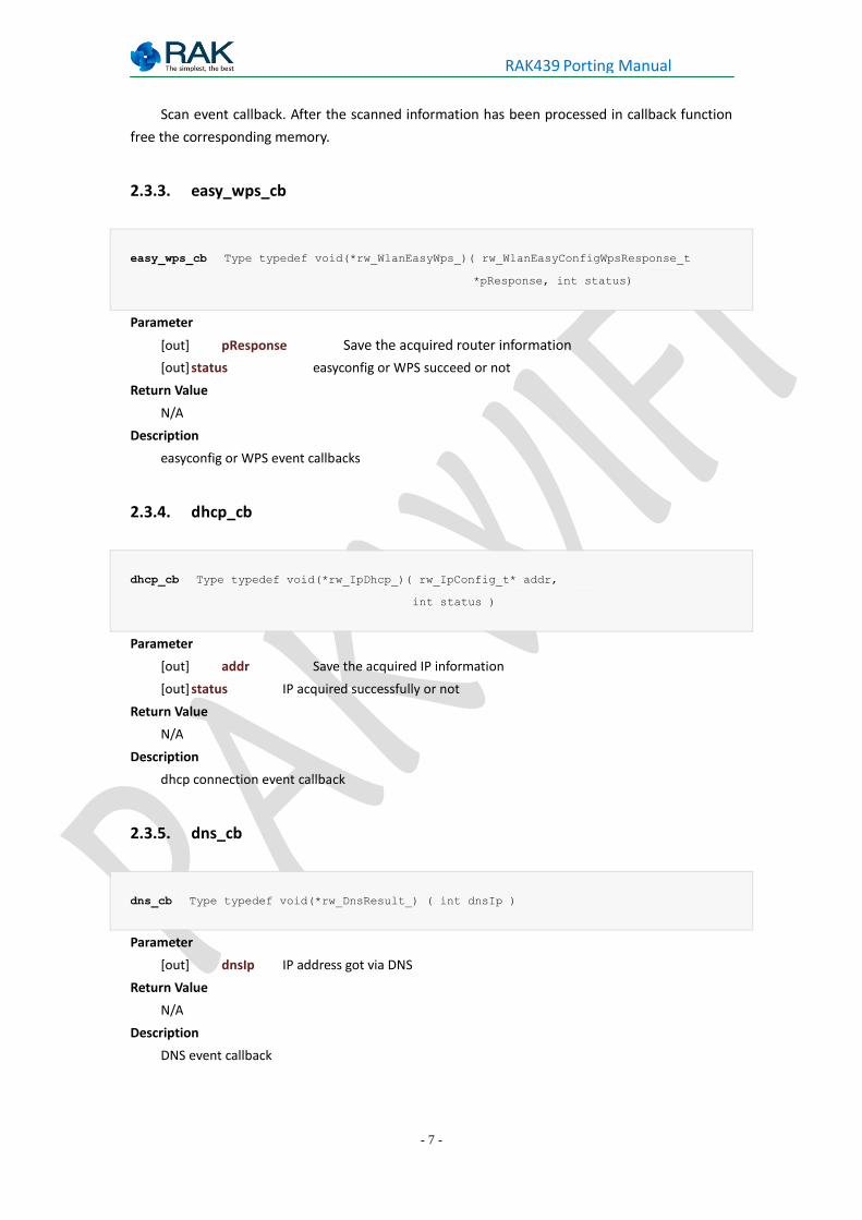
Scan event callback. After the scanned information has been processed in callback function
free the corresponding memory.
2.3.3. easy_wps_cb
easy_wps_cb Type typedef void(*rw_WlanEasyWps_)( rw_WlanEasyConfigWpsResponse_t
*pResponse, int status)
Parameter
[out] pResponse Save the acquired router information
[out] status easyconfig or WPS succeed or not
Return Value
N/A
Description
easyconfig or WPS event callbacks
2.3.4. dhcp_cb
dhcp_cb Type typedef void(*rw_IpDhcp_)( rw_IpConfig_t* addr,
int status )
Parameter
[out] addr Save the acquired IP information
[out] status IP acquired successfully or not
Return Value
N/A
Description
dhcp connection event callback
2.3.5. dns_cb
dns_cb Type typedef void(*rw_DnsResult_) ( int dnsIp )
Parameter
[out] dnsIp IP address got via DNS
Return Value
N/A
Description
DNS event callback
- 8 -
RAK439 Porting Manual
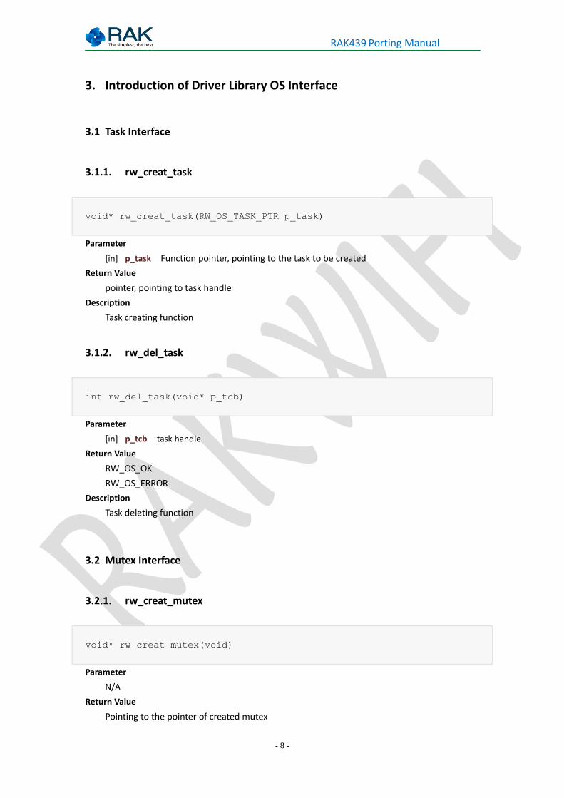
3. Introduction of Driver Library OS Interface
3.1 Task Interface
3.1.1. rw_creat_task
void* rw_creat_task(RW_OS_TASK_PTR p_task)
Parameter
[in] p_task Function pointer, pointing to the task to be created
Return Value
pointer, pointing to task handle
Description
Task creating function
3.1.2. rw_del_task
int rw_del_task(void* p_tcb)
Parameter
[in] p_tcb task handle
Return Value
RW_OS_OK
RW_OS_ERROR
Description
Task deleting function
3.2 Mutex Interface
3.2.1. rw_creat_mutex
void* rw_creat_mutex(void)
Parameter
N/A
Return Value
Pointing to the pointer of created mutex
- 9 -
RAK439 Porting Manual
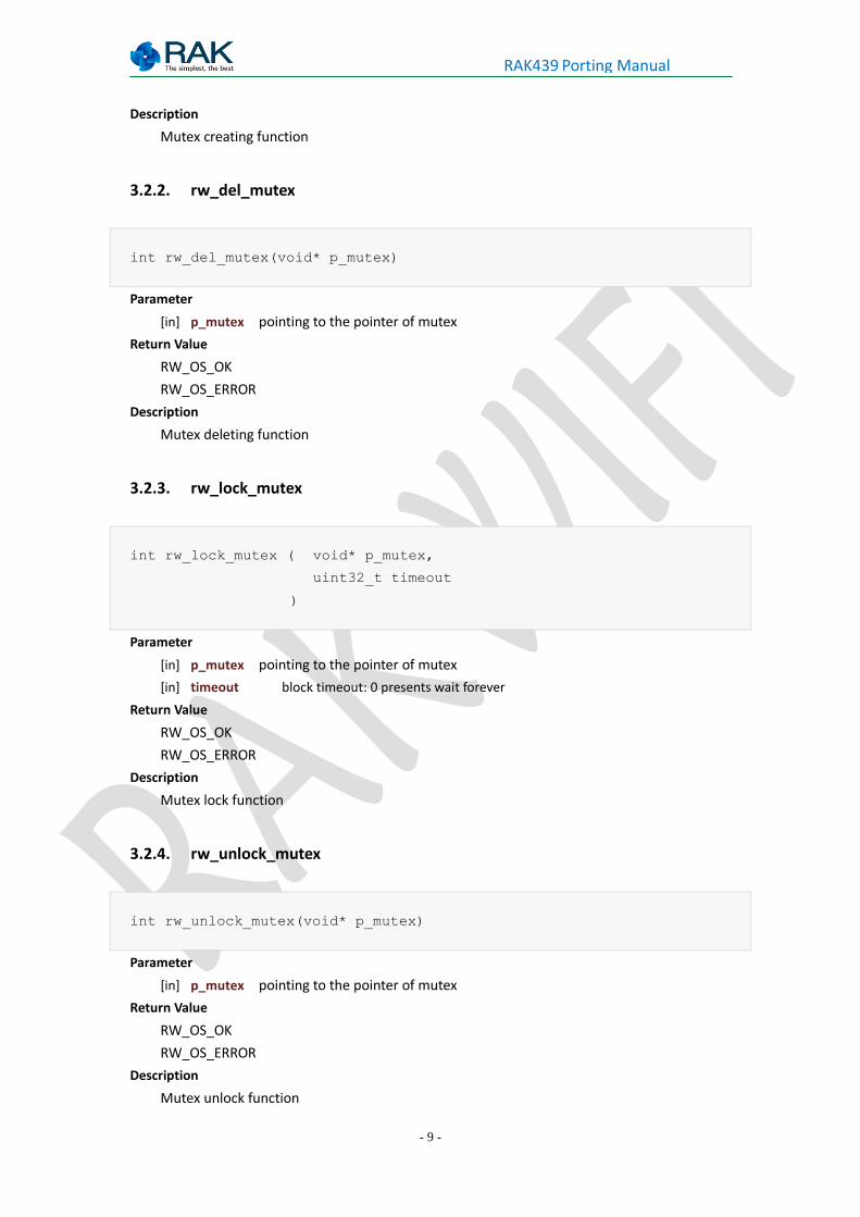
Description
Mutex creating function
3.2.2. rw_del_mutex
int rw_del_mutex(void* p_mutex)
Parameter
[in] p_mutex pointing to the pointer of mutex
Return Value
RW_OS_OK
RW_OS_ERROR
Description
Mutex deleting function
3.2.3. rw_lock_mutex
int rw_lock_mutex ( void* p_mutex,
uint32_t timeout
)
Parameter
[in] p_mutex pointing to the pointer of mutex
[in] timeout block timeout: 0 presents wait forever
Return Value
RW_OS_OK
RW_OS_ERROR
Description
Mutex lock function
3.2.4. rw_unlock_mutex
int rw_unlock_mutex(void* p_mutex)
Parameter
[in] p_mutex pointing to the pointer of mutex
Return Value
RW_OS_OK
RW_OS_ERROR
Description
Mutex unlock function
- 10 -
RAK439 Porting Manual
3.3 Semaphore Interface
3.3.1. rw_creat_sem
void* rw_creat_sem(void)
Parameter
N/A
Return Value
pointing to the semaphore to be created
Description
Semaphore creating function
3.3.2. rw_del_sem
int rw_del_sem(void* p_sem)
Parameter
[in] p_sem pointing to the pointer of semaphore
Return Value
RW_OS_OK
RW_OS_ERROR
Description
Semaphore deleting function
3.3.3. rw_post_sem
int rw_post_sem(void* p_sem)
Parameter
[in] p_sem pointing to the pointer of semaphore
Return Value
RW_OS_OK
RW_OS_ERROR
Description
Semaphore releasing function
- 11 -
RAK439 Porting Manual
3.3.4. rw_pend_sem
int rw_pend_sem ( void* p_sem,
uint32_t timeout
)
Parameter
[in] p_sem pointing to the pointer of semaphore
[in] timeout block timeout: 0 presents wait forever
Return Value
RW_OS_OK
RW_OS_TIME_OUT
RW_OS_ERROR
Description
Semaphore blocking function
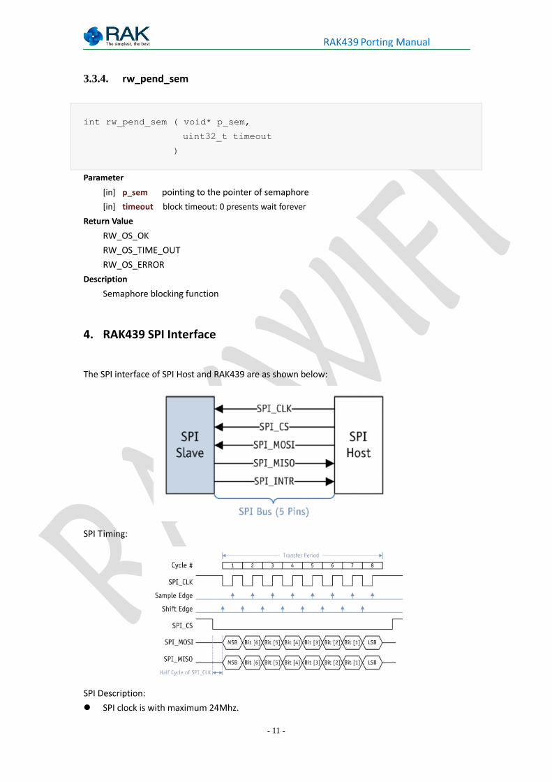
4. RAK439 SPI Interface
The SPI interface of SPI Host and RAK439 are as shown below:
SPI Timing:
SPI Description:
SPI clock is with maximum 24Mhz.
- 12 -
RAK439 Porting Manual
Module is in SPI slave mode.
SPI transfer order is MSB first (MSB).
When SPI clock is idle, power level is high, the polarity is 1 (CPOL = 1); send data on the SPI
clock rising edge (SPI_MOSI), send data on the falling edge (SPI_MISO), the phase is 1 (CHPA
= 1).
Data length of SPI transmit is 8 bit
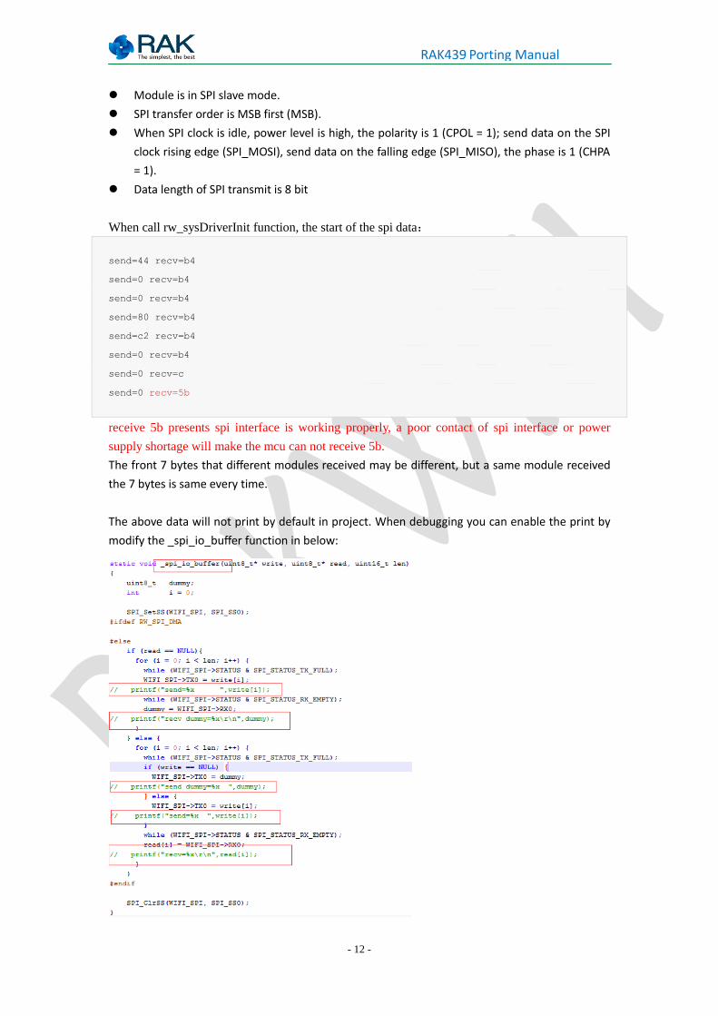
When call rw_sysDriverInit function, the start of the spi data:
send=44 recv=b4
send=0 recv=b4
send=0 recv=b4
send=80 recv=b4
send=c2 recv=b4
send=0 recv=b4
send=0 recv=c
send=0 recv=5b
receive 5b presents spi interface is working properly, a poor contact of spi interface or power
supply shortage will make the mcu can not receive 5b.
The front 7 bytes that different modules received may be different, but a same module received
the 7 bytes is same every time.
The above data will not print by default in project. When debugging you can enable the print by
modify the _spi_io_buffer function in below:
- 13 -
RAK439 Porting Manual
5. RAK439 External Interrupt
The external interrupt pin is set to be enabled by falling edge
6. STM32F4 Platform Porting Example
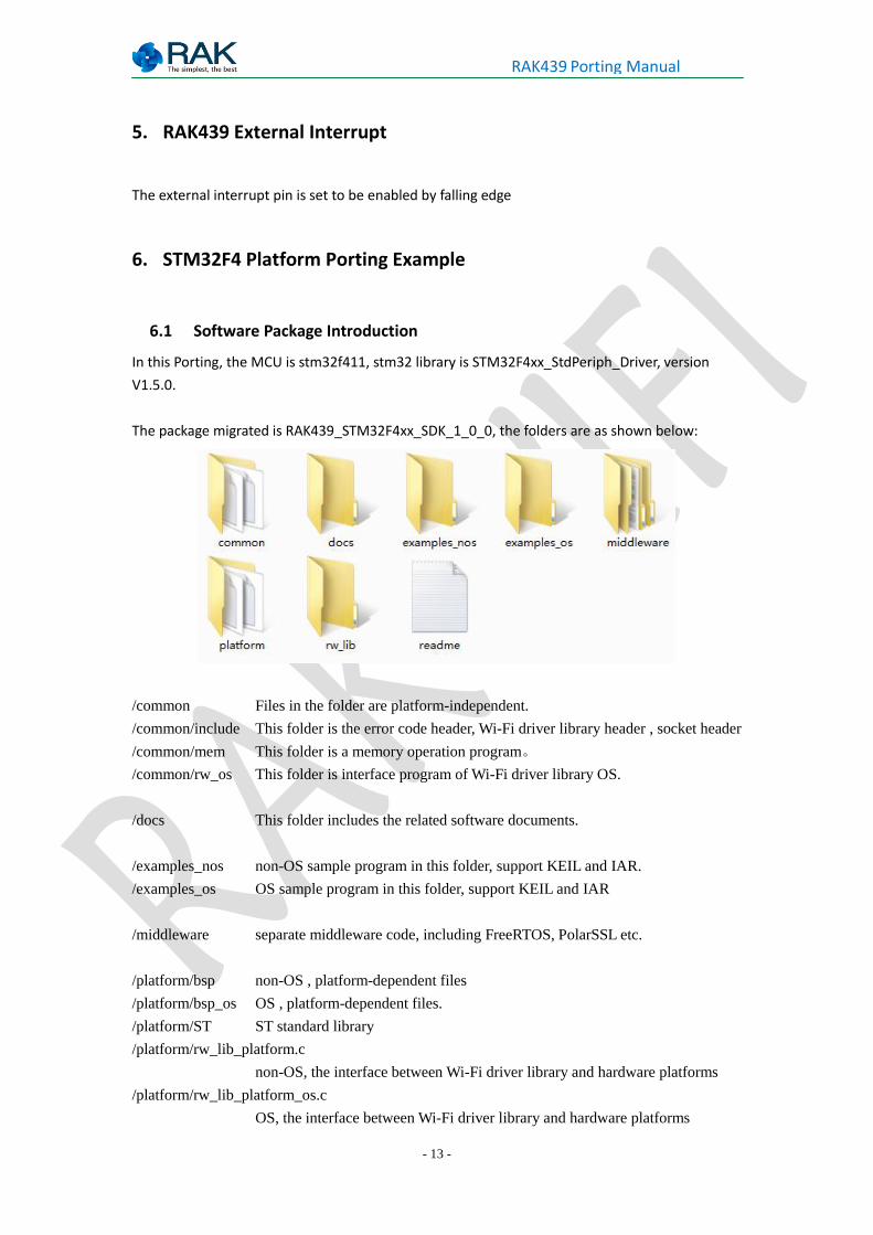
6.1 Software Package Introduction
In this Porting, the MCU is stm32f411, stm32 library is STM32F4xx_StdPeriph_Driver, version
V1.5.0.
The package migrated is RAK439_STM32F4xx_SDK_1_0_0, the folders are as shown below:
/common Files in the folder are platform-independent.
/common/include This folder is the error code header, Wi-Fi driver library header , socket header
/common/mem This folder is a memory operation program。
/common/rw_os This folder is interface program of Wi-Fi driver library OS.
/docs This folder includes the related software documents.
/examples_nos non-OS sample program in this folder, support KEIL and IAR.
/examples_os OS sample program in this folder, support KEIL and IAR
/middleware separate middleware code, including FreeRTOS, PolarSSL etc.
/platform/bsp non-OS , platform-dependent files
/platform/bsp_os OS , platform-dependent files.
/platform/ST ST standard library
/platform/rw_lib_platform.c
non-OS, the interface between Wi-Fi driver library and hardware platforms
/platform/rw_lib_platform_os.c
OS, the interface between Wi-Fi driver library and hardware platforms
- 14 -
RAK439 Porting Manual
/rw_lib Wi-Fi driver library file
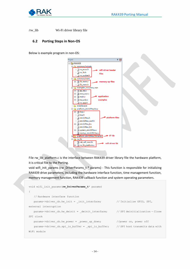
6.2 Porting Steps in Non-OS
Below is example program in non-OS:
File rw_lib_platform.c is the interface between RAK439 driver library file the hardware platform,
it is critical file to the Porting.
void wifi_init_params (rw_DriverParams_t * params) - This function is responsible for initializing
RAK439 drive parameters, including the hardware interface function, time management function,
memory management function, RAK439 callback function and system operating parameters.
void wifi_init_params(rw_DriverParams_t* params)
{
// Hardware interface function
params->driver_cb.hw_init = _init_interface; // Initialize GPIO, SPI,
external interruption
params->driver_cb.hw_deinit = _deinit_interface; // SPI deinitialization - Close
SPI clock
params->driver_cb.hw_power = _power_up_down; //power on, power off
params->driver_cb.spi_io_buffer = _spi_io_buffer; // SPI host transmits data with
WiFi module
- 15 -
RAK439 Porting Manual
params->driver_cb.toggle_irq = _ext_interrupt; // External interruption On,
Off
// Time management function
params->driver_cb.time_delay = delay_ms; // Delay function
params->driver_cb.Stamp_get = get_stamp; // Get System Time
// Memory management function
params->driver_cb.driver_free = vPortFree; // Release memory
params->driver_cb.driver_malloc = pvPortMalloc; // Allocate memory
//wifi callback funtion
params->app_cb.conn_cb = connect_callback; // callback event of connecting
to router
params->app_cb.scan_cb = scan_callback; // Scan callback event
params->app_cb.dhcp_cb = ip_callback; //Get IP callback event
params->app_cb.dns_cb = dns_ipcallback; //dns callback
params->app_cb.easy_wps_cb = wps_easy_callback; //WPS, easyconfig callback
events
params->app_cb.tcpc_cb = tcpclient_callback; //tcp callback event
// System operating parameters setup
params->rx_queue_num = 1; // number of receive data buffer
params->scan_max_num = 10; // number of scan buffer
params->socket_max_num = 8; //number of socket buffer
params->country_code = "CN"; // Module country code, CN (1-13), JP(1-14),
US(1-11)
params->host_name = "rakmodule"; // After DHCP, the host name of module displayed
in the router client list
}
memory management function, Wi-Fi callback function, system operating parameters
settings is independent with hardware platform, users can use the default settings.
Time management function will be implemented according to different hardware platforms.
Single-chip of stm32f411 in this Porting comes with a 24 systick, the API that operates this
systick also in ST library; users can refer to the Porting.
hardware interface function is associated with hardware platform, is also the most
important part of the Porting. The following will detail the various hardware interface
functions.
- 16 -
RAK439 Porting Manual
6.2.1. hw_init Implementation
GPIO, SPI, external interrupt initialization
static uint32_t _init_interface(void)
{
WIFI_GPIO_Init(); // Initialize Wi-Fi module power switch pins (optional), reset
pin, SPI chip select pin
WIFI_SPI_Init (); // Initialize SPI Host
WIFI_INT_Init (); // Initialize the external interrupt pin connected with Wi-Fi
module
}
1. GPIO pin Initialization - Initialize WiFi module power switch pins (optional), reset pin, SPI
chip select pin.
void WIFI_GPIO_Init(void)
{
GPIO_InitTypeDef GPIO_InitStructure;
/* GPIOA GPIOB Peripheral clock enable */
RCC_AHB1PeriphClockCmd(WIFI_PWD_GPIO_CLK|WIFI_CS_GPIO_CLK, ENABLE); // Enable GPIO
Clock /* Initialize Wi-Fi module power switch pin, optional */
#if defined (USE_WIFI_POWER_FET)
RCC_AHB1PeriphClockCmd(WIFI_FET_GPIO_CLK, ENABLE);
GPIO_InitStructure.GPIO_Pin = WIFI_FET_PIN;
GPIO_InitStructure.GPIO_Mode = GPIO_Mode_OUT;
GPIO_InitStructure.GPIO_OType = GPIO_OType_PP;
GPIO_InitStructure.GPIO_Speed = GPIO_Speed_50MHz;
GPIO_InitStructure.GPIO_PuPd = GPIO_PuPd_UP;
GPIO_Init(WIFI_FET_GPIO_PORT, &GPIO_InitStructure);
GPIO_WriteBit(WIFI_FET_GPIO_PORT, WIFI_FET_PIN, Bit_SET);
#endif
/* Initialize reset pin */
GPIO_InitStructure.GPIO_Pin = WIFI_PWD_PIN;
GPIO_InitStructure.GPIO_Mode = GPIO_Mode_OUT;
GPIO_InitStructure.GPIO_OType = GPIO_OType_PP;
GPIO_InitStructure.GPIO_Speed = GPIO_Speed_50MHz;
GPIO_InitStructure.GPIO_PuPd = GPIO_PuPd_UP;
GPIO_Init(WIFI_PWD_GPIO_PORT, &GPIO_InitStructure);
GPIO_WriteBit(WIFI_PWD_GPIO_PORT, WIFI_PWD_PIN, Bit_RESET);
/* Initialize SPI chip select pin */
GPIO_InitStructure.GPIO_Pin = WIFI_CS_PIN;
GPIO_InitStructure.GPIO_Mode = GPIO_Mode_OUT;
- 17 -
RAK439 Porting Manual
GPIO_InitStructure.GPIO_OType = GPIO_OType_PP;
GPIO_InitStructure.GPIO_Speed = GPIO_Speed_50MHz;
GPIO_InitStructure.GPIO_PuPd = GPIO_PuPd_NOPULL;
GPIO_Init(WIFI_CS_GPIO_PORT, &GPIO_InitStructure);
GPIO_WriteBit(WIFI_CS_GPIO_PORT, WIFI_CS_PIN, Bit_SET);
}
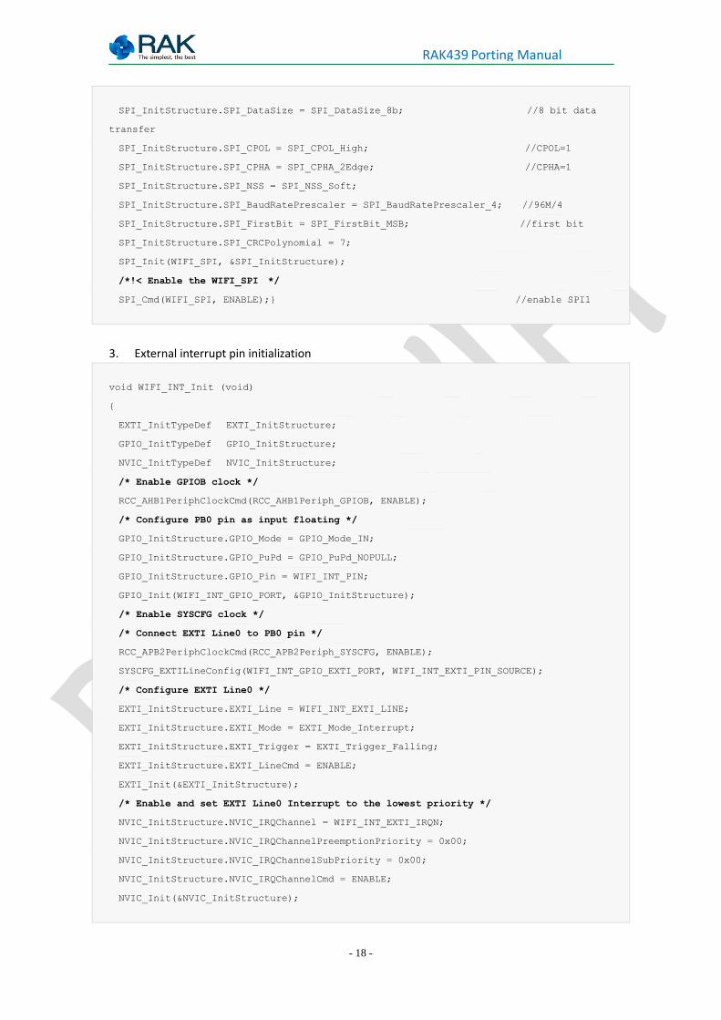
2. SPI host initialization
SPI Initialization: configuration as SPI master, full-duplex mode, CHPA = 1 CPOL = 1, 8-bit data
transfer, descending bit order.
void SPI1_Config(void)
{
GPIO_InitTypeDef GPIO_InitStructure;
SPI_InitTypeDef SPI_InitStructure;
/*!< Enable the SPI clock */
WIFI_SPI_CLK_INIT(WIFI_SPI_CLK, ENABLE);
/*!< Enable GPIO clocks */
RCC_AHB1PeriphClockCmd(WIFI_SPI_SCK_GPIO_CLK | WIFI_SPI_MISO_GPIO_CLK |
WIFI_SPI_MOSI_GPIO_CLK , ENABLE);
/*!< SPI pins configuration *************************************************/
/*!< Connect SPI pins to AF */
GPIO_PinAFConfig(WIFI_SPI_SCK_GPIO_PORT, WIFI_SPI_SCK_SOURCE, WIFI_SPI_SCK_AF);
GPIO_PinAFConfig(WIFI_SPI_MISO_GPIO_PORT, WIFI_SPI_MISO_SOURCE, WIFI_SPI_MISO_AF);
GPIO_PinAFConfig(WIFI_SPI_MOSI_GPIO_PORT, WIFI_SPI_MOSI_SOURCE, WIFI_SPI_MOSI_AF);
GPIO_InitStructure.GPIO_Mode = GPIO_Mode_AF;
GPIO_InitStructure.GPIO_Speed = GPIO_Speed_50MHz;
GPIO_InitStructure.GPIO_OType = GPIO_OType_PP;
GPIO_InitStructure.GPIO_PuPd = GPIO_PuPd_DOWN;
/*!< SPI SCK pin configuration */
GPIO_InitStructure.GPIO_Pin = WIFI_SPI_SCK_PIN;
GPIO_Init(WIFI_SPI_SCK_GPIO_PORT, &GPIO_InitStructure);
/*!< SPI MOSI pin configuration */
GPIO_InitStructure.GPIO_Pin = WIFI_SPI_MOSI_PIN;
GPIO_Init(WIFI_SPI_MOSI_GPIO_PORT, &GPIO_InitStructure);
/*!< SPI MISO pin configuration */
GPIO_InitStructure.GPIO_Pin = WIFI_SPI_MISO_PIN;
GPIO_Init(WIFI_SPI_MISO_GPIO_PORT, &GPIO_InitStructure);
/*!< SPI configuration */
SPI_InitStructure.SPI_Direction = SPI_Direction_2Lines_FullDuplex; // Full-duplex
mode
SPI_InitStructure.SPI_Mode = SPI_Mode_Master; // Host Mode
- 18 -
RAK439 Porting Manual
SPI_InitStructure.SPI_DataSize = SPI_DataSize_8b; //8 bit data
transfer
SPI_InitStructure.SPI_CPOL = SPI_CPOL_High; //CPOL=1
SPI_InitStructure.SPI_CPHA = SPI_CPHA_2Edge; //CPHA=1
SPI_InitStructure.SPI_NSS = SPI_NSS_Soft;
SPI_InitStructure.SPI_BaudRatePrescaler = SPI_BaudRatePrescaler_4; //96M/4
SPI_InitStructure.SPI_FirstBit = SPI_FirstBit_MSB; //first bit
SPI_InitStructure.SPI_CRCPolynomial = 7;
SPI_Init(WIFI_SPI, &SPI_InitStructure);
/*!< Enable the WIFI_SPI */
SPI_Cmd(WIFI_SPI, ENABLE);} //enable SPI1
3. External interrupt pin initialization
void WIFI_INT_Init (void)
{
EXTI_InitTypeDef EXTI_InitStructure;
GPIO_InitTypeDef GPIO_InitStructure;
NVIC_InitTypeDef NVIC_InitStructure;
/* Enable GPIOB clock */
RCC_AHB1PeriphClockCmd(RCC_AHB1Periph_GPIOB, ENABLE);
/* Configure PB0 pin as input floating */
GPIO_InitStructure.GPIO_Mode = GPIO_Mode_IN;
GPIO_InitStructure.GPIO_PuPd = GPIO_PuPd_NOPULL;
GPIO_InitStructure.GPIO_Pin = WIFI_INT_PIN;
GPIO_Init(WIFI_INT_GPIO_PORT, &GPIO_InitStructure);
/* Enable SYSCFG clock */
/* Connect EXTI Line0 to PB0 pin */
RCC_APB2PeriphClockCmd(RCC_APB2Periph_SYSCFG, ENABLE);
SYSCFG_EXTILineConfig(WIFI_INT_GPIO_EXTI_PORT, WIFI_INT_EXTI_PIN_SOURCE);
/* Configure EXTI Line0 */
EXTI_InitStructure.EXTI_Line = WIFI_INT_EXTI_LINE;
EXTI_InitStructure.EXTI_Mode = EXTI_Mode_Interrupt;
EXTI_InitStructure.EXTI_Trigger = EXTI_Trigger_Falling;
EXTI_InitStructure.EXTI_LineCmd = ENABLE;
EXTI_Init(&EXTI_InitStructure);
/* Enable and set EXTI Line0 Interrupt to the lowest priority */
NVIC_InitStructure.NVIC_IRQChannel = WIFI_INT_EXTI_IRQN;
NVIC_InitStructure.NVIC_IRQChannelPreemptionPriority = 0x00;
NVIC_InitStructure.NVIC_IRQChannelSubPriority = 0x00;
NVIC_InitStructure.NVIC_IRQChannelCmd = ENABLE;
NVIC_Init(&NVIC_InitStructure);
- 19 -
RAK439 Porting Manual
}
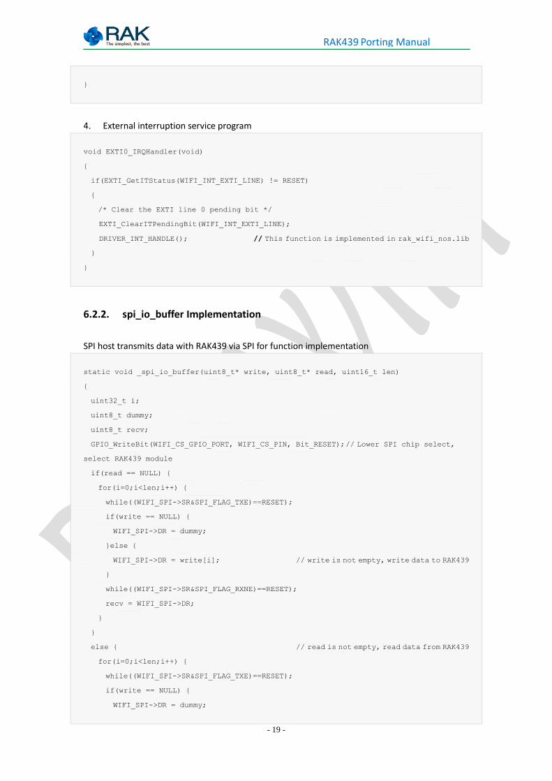
4. External interruption service program
void EXTI0_IRQHandler(void)
{
if(EXTI_GetITStatus(WIFI_INT_EXTI_LINE) != RESET)
{
/* Clear the EXTI line 0 pending bit */
EXTI_ClearITPendingBit(WIFI_INT_EXTI_LINE);
DRIVER_INT_HANDLE(); // This function is implemented in rak_wifi_nos.lib
}
}
6.2.2. spi_io_buffer Implementation
SPI host transmits data with RAK439 via SPI for function implementation
static void _spi_io_buffer(uint8_t* write, uint8_t* read, uint16_t len)
{
uint32_t i;
uint8_t dummy;
uint8_t recv;
GPIO_WriteBit(WIFI_CS_GPIO_PORT, WIFI_CS_PIN, Bit_RESET); // Lower SPI chip select,
select RAK439 module
if(read == NULL) {
for(i=0;i<len;i++) {
while((WIFI_SPI->SR&SPI_FLAG_TXE)==RESET);
if(write == NULL) {
WIFI_SPI->DR = dummy;
}else {
WIFI_SPI->DR = write[i]; // write is not empty, write data to RAK439
}
while((WIFI_SPI->SR&SPI_FLAG_RXNE)==RESET);
recv = WIFI_SPI->DR;
}
}
else { // read is not empty, read data from RAK439
for(i=0;i<len;i++) {
while((WIFI_SPI->SR&SPI_FLAG_TXE)==RESET);
if(write == NULL) {
WIFI_SPI->DR = dummy;
- 20 -
RAK439 Porting Manual
}else {
WIFI_SPI->DR = write[i];
}
while((WIFI_SPI->SR&SPI_FLAG_RXNE)==RESET);
read[i] = WIFI_SPI->DR;
}
}
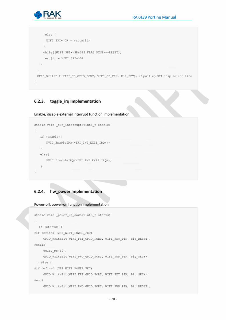
GPIO_WriteBit(WIFI_CS_GPIO_PORT, WIFI_CS_PIN, Bit_SET); // pull up SPI chip select line
}
6.2.3. toggle_irq Implementation
Enable, disable external interrupt function implementation
static void _ext_interrupt(uint8_t enable)
{
if (enable){
NVIC_EnableIRQ(WIFI_INT_EXTI_IRQN);
}
else{
NVIC_DisableIRQ(WIFI_INT_EXTI_IRQN);
}
}
6.2.4. hw_power Implementation
Power-off, power-on function implementation
static void _power_up_down(uint8_t status)
{
if (status) {
#if defined (USE_WIFI_POWER_FET)
GPIO_WriteBit(WIFI_FET_GPIO_PORT, WIFI_FET_PIN, Bit_RESET);
#endif
delay_ms(10);
GPIO_WriteBit(WIFI_PWD_GPIO_PORT, WIFI_PWD_PIN, Bit_SET);
} else {
#if defined (USE_WIFI_POWER_FET)
GPIO_WriteBit(WIFI_FET_GPIO_PORT, WIFI_FET_PIN, Bit_SET);
#endi
GPIO_WriteBit(WIFI_PWD_GPIO_PORT, WIFI_PWD_PIN, Bit_RESET);
- 21 -
RAK439 Porting Manual
}
}
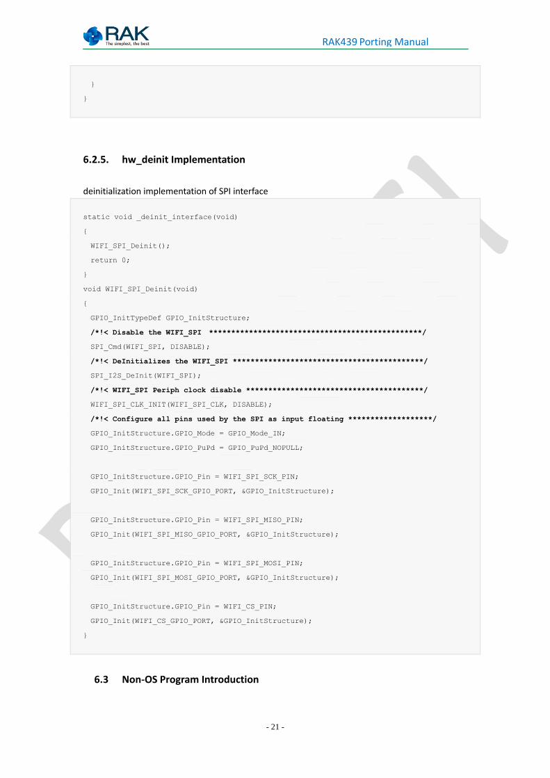
6.2.5. hw_deinit Implementation
deinitialization implementation of SPI interface
static void _deinit_interface(void)
{
WIFI_SPI_Deinit();
return 0;
}
void WIFI_SPI_Deinit(void)
{
GPIO_InitTypeDef GPIO_InitStructure;
/*!< Disable the WIFI_SPI ************************************************/
SPI_Cmd(WIFI_SPI, DISABLE);
/*!< DeInitializes the WIFI_SPI *******************************************/
SPI_I2S_DeInit(WIFI_SPI);
/*!< WIFI_SPI Periph clock disable ****************************************/
WIFI_SPI_CLK_INIT(WIFI_SPI_CLK, DISABLE);
/*!< Configure all pins used by the SPI as input floating *******************/
GPIO_InitStructure.GPIO_Mode = GPIO_Mode_IN;
GPIO_InitStructure.GPIO_PuPd = GPIO_PuPd_NOPULL;
GPIO_InitStructure.GPIO_Pin = WIFI_SPI_SCK_PIN;
GPIO_Init(WIFI_SPI_SCK_GPIO_PORT, &GPIO_InitStructure);
GPIO_InitStructure.GPIO_Pin = WIFI_SPI_MISO_PIN;
GPIO_Init(WIFI_SPI_MISO_GPIO_PORT, &GPIO_InitStructure);
GPIO_InitStructure.GPIO_Pin = WIFI_SPI_MOSI_PIN;
GPIO_Init(WIFI_SPI_MOSI_GPIO_PORT, &GPIO_InitStructure);
GPIO_InitStructure.GPIO_Pin = WIFI_CS_PIN;
GPIO_Init(WIFI_CS_GPIO_PORT, &GPIO_InitStructure);
}
6.3 Non-OS Program Introduction
- 22 -
RAK439 Porting Manual
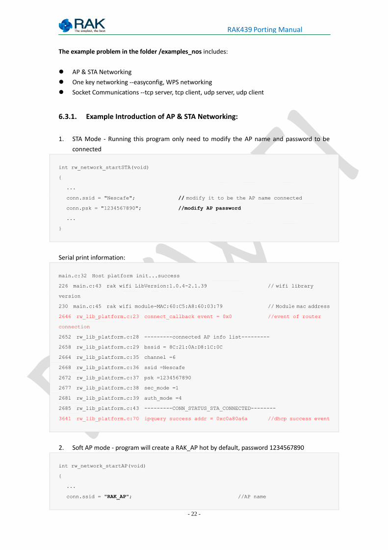
The example problem in the folder /examples_nos includes:
AP & STA Networking
One key networking --easyconfig, WPS networking
Socket Communications --tcp server, tcp client, udp server, udp client
6.3.1. Example Introduction of AP & STA Networking:
1. STA Mode - Running this program only need to modify the AP name and password to be
connected
int rw_network_startSTA(void)
{
...
conn.ssid = "Nescafe"; // modify it to be the AP name connected
conn.psk = "1234567890"; //modify AP password
...
}
Serial print information:
main.c:32 Host platform init...success
226 main.c:43 rak wifi LibVersion:1.0.4-2.1.39 // wifi library
version
230 main.c:45 rak wifi module-MAC:60:C5:A8:60:03:79 // Module mac address
2646 rw_lib_platform.c:23 connect_callback event = 0x0 //event of router
connection
2652 rw_lib_platform.c:28 ---------connected AP info list---------
2658 rw_lib_platform.c:29 bssid = 8C:21:0A:D8:1C:0C
2664 rw_lib_platform.c:35 channel =6
2668 rw_lib_platform.c:36 ssid =Nescafe
2672 rw_lib_platform.c:37 psk =1234567890
2677 rw_lib_platform.c:38 sec_mode =1
2681 rw_lib_platform.c:39 auth_mode =4
2685 rw_lib_platform.c:43 ---------CONN_STATUS_STA_CONNECTED--------
3641 rw_lib_platform.c:70 ipquery success addr = 0xc0a80a6a //dhcp success event
2. Soft AP mode - program will create a RAK_AP hot by default, password 1234567890
int rw_network_startAP(void)
{
...
conn.ssid = "RAK_AP"; //AP name
- 23 -
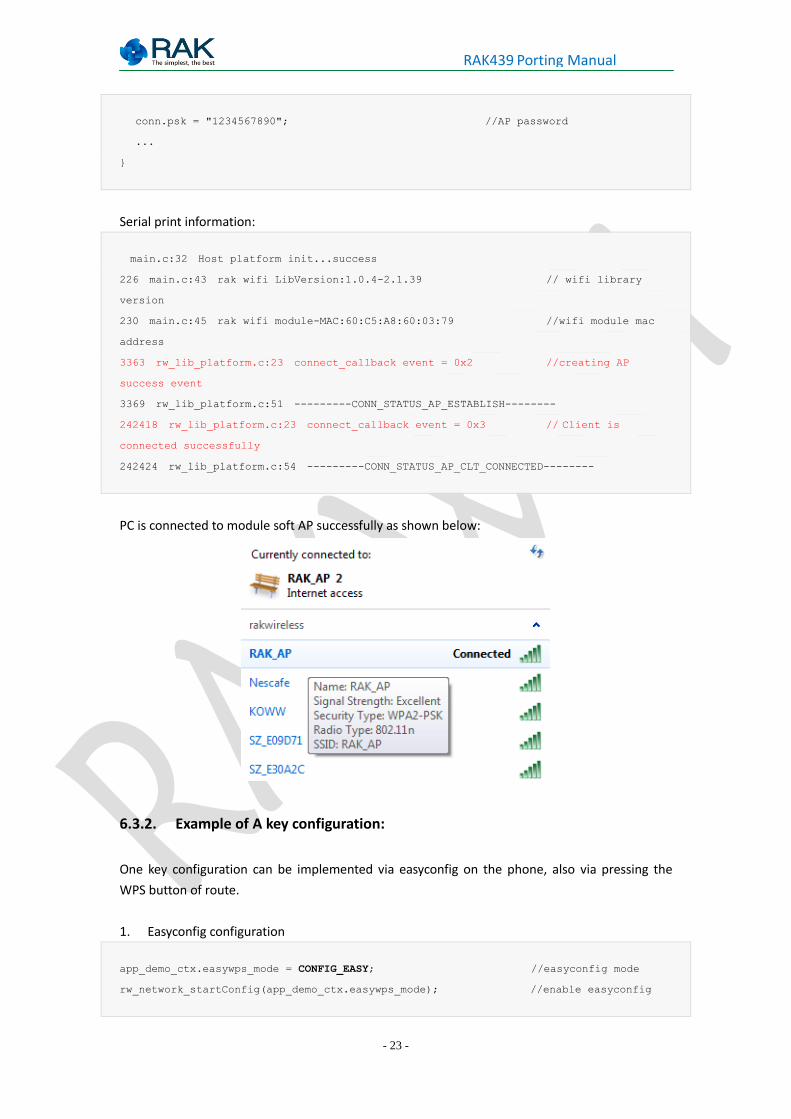
RAK439 Porting Manual
conn.psk = "1234567890"; //AP password
...
}
Serial print information:
main.c:32 Host platform init...success
226 main.c:43 rak wifi LibVersion:1.0.4-2.1.39 // wifi library
version
230 main.c:45 rak wifi module-MAC:60:C5:A8:60:03:79 //wifi module mac
address
3363 rw_lib_platform.c:23 connect_callback event = 0x2 //creating AP
success event
3369 rw_lib_platform.c:51 ---------CONN_STATUS_AP_ESTABLISH--------
242418 rw_lib_platform.c:23 connect_callback event = 0x3 // Client is
connected successfully
242424 rw_lib_platform.c:54 ---------CONN_STATUS_AP_CLT_CONNECTED--------
PC is connected to module soft AP successfully as shown below:
6.3.2. Example of A key configuration:
One key configuration can be implemented via easyconfig on the phone, also via pressing the
WPS button of route.
1. Easyconfig configuration
app_demo_ctx.easywps_mode = CONFIG_EASY; //easyconfig mode
rw_network_startConfig(app_demo_ctx.easywps_mode); //enable easyconfig
- 24 -
RAK439 Porting Manual
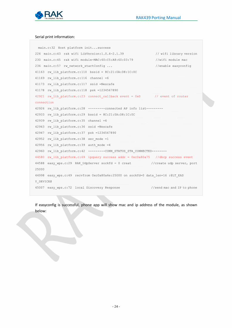
Serial print information:
main.c:32 Host platform init...success
226 main.c:43 rak wifi LibVersion:1.0.4-2.1.39 // wifi library version
230 main.c:45 rak wifi module-MAC:60:C5:A8:60:03:79 //wifi module mac
236 main.c:57 rw_network_startConfig ... //enable easyconfig
41163 rw_lib_platform.c:110 bssid = 8C:21:0A:D8:1C:0C
41169 rw_lib_platform.c:116 channel =6
41173 rw_lib_platform.c:117 ssid =Nescafe
41178 rw_lib_platform.c:118 psk =1234567890
42921 rw_lib_platform.c:23 connect_callback event = 0x0 // event of router
connection
42926 rw_lib_platform.c:28 ---------connected AP info list---------
42933 rw_lib_platform.c:29 bssid = 8C:21:0A:D8:1C:0C
42939 rw_lib_platform.c:35 channel =6
42943 rw_lib_platform.c:36 ssid =Nescafe
42947 rw_lib_platform.c:37 psk =1234567890
42952 rw_lib_platform.c:38 sec_mode =1
42956 rw_lib_platform.c:39 auth_mode =4
42960 rw_lib_platform.c:42 ---------CONN_STATUS_STA_CONNECTED--------
44580 rw_lib_platform.c:69 ipquery success addr = 0xc0a80a75 //dhcp success event
44588 easy_wps.c:29 RAK_UdpServer sockfd = 0 creat //create udp server, port
25000
44998 easy_wps.c:49 recvfrom 0xc0a80a6e:25000 on sockfd=0 data_len=16 :@LT_EAS
Y_DEVICE@
45007 easy_wps.c:72 local Discovery Response //send mac and IP to phone
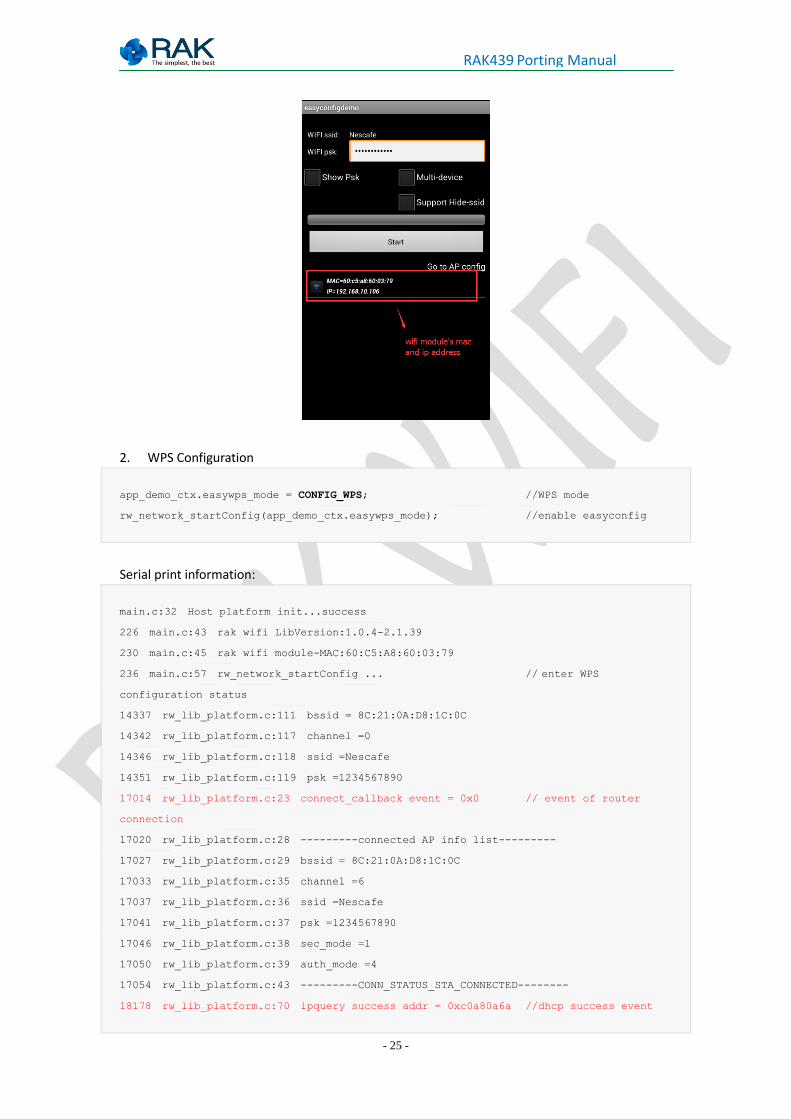
If easyconfig is successful, phone app will show mac and ip address of the module, as shown
below:
- 25 -
RAK439 Porting Manual
2. WPS Configuration
app_demo_ctx.easywps_mode = CONFIG_WPS; //WPS mode
rw_network_startConfig(app_demo_ctx.easywps_mode); //enable easyconfig
Serial print information:
main.c:32 Host platform init...success
226 main.c:43 rak wifi LibVersion:1.0.4-2.1.39
230 main.c:45 rak wifi module-MAC:60:C5:A8:60:03:79
236 main.c:57 rw_network_startConfig ... // enter WPS
configuration status
14337 rw_lib_platform.c:111 bssid = 8C:21:0A:D8:1C:0C
14342 rw_lib_platform.c:117 channel =0
14346 rw_lib_platform.c:118 ssid =Nescafe
14351 rw_lib_platform.c:119 psk =1234567890
17014 rw_lib_platform.c:23 connect_callback event = 0x0 // event of router
connection
17020 rw_lib_platform.c:28 ---------connected AP info list---------
17027 rw_lib_platform.c:29 bssid = 8C:21:0A:D8:1C:0C
17033 rw_lib_platform.c:35 channel =6
17037 rw_lib_platform.c:36 ssid =Nescafe
17041 rw_lib_platform.c:37 psk =1234567890
17046 rw_lib_platform.c:38 sec_mode =1
17050 rw_lib_platform.c:39 auth_mode =4
17054 rw_lib_platform.c:43 ---------CONN_STATUS_STA_CONNECTED--------
18178 rw_lib_platform.c:70 ipquery success addr = 0xc0a80a6a //dhcp success event
- 26 -
RAK439 Porting Manual
18186 easy_wps.c:29 RAK_UdpServer sockfd = 0 creat //creat udp server
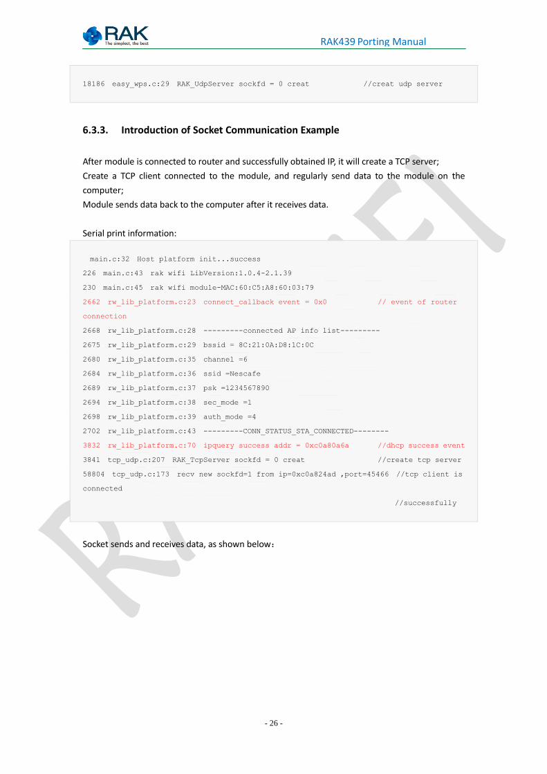
6.3.3. Introduction of Socket Communication Example
After module is connected to router and successfully obtained IP, it will create a TCP server;
Create a TCP client connected to the module, and regularly send data to the module on the
computer;
Module sends data back to the computer after it receives data.
Serial print information:
main.c:32 Host platform init...success
226 main.c:43 rak wifi LibVersion:1.0.4-2.1.39
230 main.c:45 rak wifi module-MAC:60:C5:A8:60:03:79
2662 rw_lib_platform.c:23 connect_callback event = 0x0 // event of router
connection
2668 rw_lib_platform.c:28 ---------connected AP info list---------
2675 rw_lib_platform.c:29 bssid = 8C:21:0A:D8:1C:0C
2680 rw_lib_platform.c:35 channel =6
2684 rw_lib_platform.c:36 ssid =Nescafe
2689 rw_lib_platform.c:37 psk =1234567890
2694 rw_lib_platform.c:38 sec_mode =1
2698 rw_lib_platform.c:39 auth_mode =4
2702 rw_lib_platform.c:43 ---------CONN_STATUS_STA_CONNECTED--------
3832 rw_lib_platform.c:70 ipquery success addr = 0xc0a80a6a //dhcp success event
3841 tcp_udp.c:207 RAK_TcpServer sockfd = 0 creat //create tcp server
58804 tcp_udp.c:173 recv new sockfd=1 from ip=0xc0a824ad ,port=45466 //tcp client is
connected
//successfully
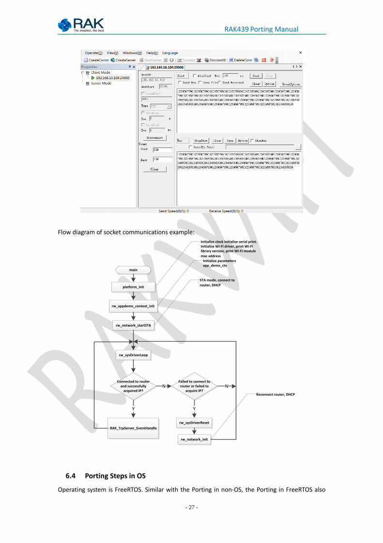
Socket sends and receives data, as shown below:
- 27 -
RAK439 Porting Manual
Flow diagram of socket communications example:
main
platform_init
rw_appdemo_context_init
rw_network_startSTA
rw_sysDriverLoop
Connected to router and successfully
acquired IP?
RAK_TcpServer_EventHandle
Y
Failed to connect to router or failed to
acquire IP?
rw_sysDriverReset
rw_network_init
N
Y
N
Initialize clock Initialize serial print.Initialize Wi-Fi driver, print Wi-Fi library version, print Wi-Fi module
mac addressInitialize parameters app_demo_ctx
STA mode, connect to
router, DHCP
Reconnect router, DHCP
6.4 Porting Steps in OS
Operating system is FreeRTOS. Similar with the Porting in non-OS, the Porting in FreeRTOS also
- 28 -
RAK439 Porting Manual
needs to start from rw_lib_platform_os.c, pay attention to the following points:
the priority of external interrupt cannot be higher than
configMAX_SYSCALL_INTERRUPT_PRIORITY (the smaller the value, the higher the priority), if
use priority grouping function NVIC_PriorityGroupConfig priority in ST library, then set
priority group to four, priority value> = 5; if use NVIC_SetPriorityGrouping in CMSIS library,
set priority group to any value, set priority value> = 5. For details, refer to
http://www.freertos.org/RTOS-Cortex-M3-M4.html
time_delay, Stamp_get are to be implemented with system functions in the OS
driver_free, driver_malloc are to be implemented with system functions in the OS
only conn_cb, easy_wps_cb are callback
The following is the OS interface implementation of Wi-Fi driver library, using the cmsis_os
interface of stm32, This interface encapsulates operating system, so that the user's application
code can be easily migrated to different operating systems.
6.4.1. rw_creat_task Implementation
void* rw_creat_task(RW_OS_TASK_PTR p_task)
{
osThreadId p_tcb; //point to task handle
// Define task start information - task name, task code address, priority, stack size
osThreadDef(task_wifi, (os_pthread)p_task, osPriorityHigh, 0,
configMINIMAL_STACK_SIZE * 7);
//create task
p_tcb = osThreadCreate (osThread(task_wifi), NULL);
return p_tcb;
}
6.4.2. rw_del_task Implementation
int rw_del_task(void* p_tcb)
{
osThreadTerminate(p_tcb); //delete task
return RW_OS_OK;
}
6.4.3. rw_creat_mutex Implementation
void* rw_creat_mutex(void)
- 29 -
RAK439 Porting Manual
{
osMutexId p_mutex;
p_mutex = osMutexCreate(osMutex(mutex)); // create mutex
return (void *)p_mutex;
}
6.4.4. rw_del_mutex
int rw_del_mutex(void* p_mutex)
{
osMutexDelete(p_mutex); //delete mutex
return RW_OS_OK;
}
6.4.5. rw_lock_mutex Implementation
int rw_lock_mutex(void* p_mutex, uint32_t timeout)
{
if(timeout == 0) {
timeout = osWaitForever;
}
osMutexWait(p_mutex,timeout); //lock mutex
return RW_OS_OK;
}
6.4.6. rw_unlock_mutex Implementation
int rw_unlock_mutex(void* p_mutex)
{
osMutexRelease(p_mutex); //free mutex
return RW_OS_OK;
}
- 30 -
RAK439 Porting Manual
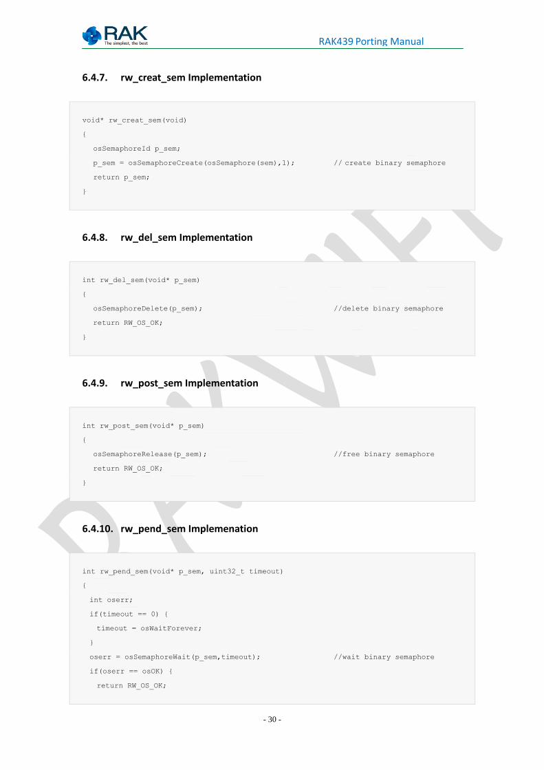
6.4.7. rw_creat_sem Implementation
void* rw_creat_sem(void)
{
osSemaphoreId p_sem;
p_sem = osSemaphoreCreate(osSemaphore(sem),1); // create binary semaphore
return p_sem;
}
6.4.8. rw_del_sem Implementation
int rw_del_sem(void* p_sem)
{
osSemaphoreDelete(p_sem); //delete binary semaphore
return RW_OS_OK;
}
6.4.9. rw_post_sem Implementation
int rw_post_sem(void* p_sem)
{
osSemaphoreRelease(p_sem); //free binary semaphore
return RW_OS_OK;
}
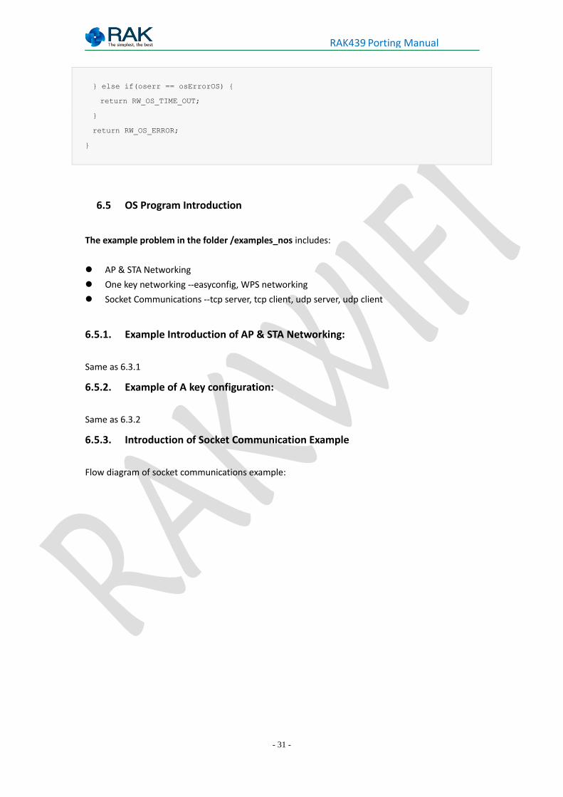
6.4.10. rw_pend_sem Implemenation
int rw_pend_sem(void* p_sem, uint32_t timeout)
{
int oserr;
if(timeout == 0) {
timeout = osWaitForever;
}
oserr = osSemaphoreWait(p_sem,timeout); //wait binary semaphore
if(oserr == osOK) {
return RW_OS_OK;
- 31 -
RAK439 Porting Manual
} else if(oserr == osErrorOS) {
return RW_OS_TIME_OUT;
}
return RW_OS_ERROR;
}
6.5 OS Program Introduction
The example problem in the folder /examples_nos includes:
AP & STA Networking
One key networking --easyconfig, WPS networking
Socket Communications --tcp server, tcp client, udp server, udp client
6.5.1. Example Introduction of AP & STA Networking:
Same as 6.3.1
6.5.2. Example of A key configuration:
Same as 6.3.2
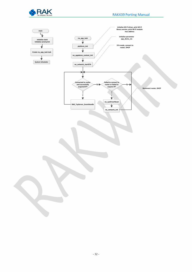
6.5.3. Introduction of Socket Communication Example
Flow diagram of socket communications example:
- 32 -
RAK439 Porting Manual
rw_app_task
platform_init
rw_appdemo_context_init
rw_network_startSTA
Connected to router and successfully
acquired IP?
RAK_TcpServer_EventHandle
Y
Failed to connect to router or failed to
acquire IP?
rw_sysDriverReset
rw_network_init
N
Y
N
initialize Wi-Fi driver, print Wi-Fi library version, print Wi-Fi module
mac address
Initialize parameter app_demo_ctx
STA mode, connect to router, DHCP
main
Initialize clockInitialize serial print
System Scheduler
Create rw_app_task task
Reconnect router, DHCP

- 33 -
RAK439 Porting Manual
7. Sales and Service
Beijing Office
FAE mailbox: [email protected]
Tel: 010-62716015
Fax: 010-62716015
Address: Room 1108, Jinyan Long Building, Deshengmenwai Xisanqi, Haidian District, Beijing
Shanghai Office
FAE mailbox: [email protected]
Tel: 021-54721182
Fax: 021-54721038
Address: Room 306, 1# Building, Ran Dong Business Center, No.2161, Lane 150 Wanyuan Road,
Minhang District, Shanghai
Shenzhen Office
FAE mailbox:[email protected]
Tel:0755- 26506594
Fax:0755-86152201
Address: Room 406, Tsinghua Building, North Science Technology Park, Nanshan District,
Shenzhen
- 34 -
RAK439 Porting Manual
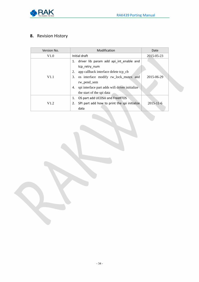
8. Revision History
Version No. Modification Date
V1.0 Initial draft 2015-05-23
V1.1
1. driver lib param add api_int_enable and
tcp_retry_num
2. app callback interface delete tcp_cb
3. os interface modify rw_lock_mutex and
rw_pend_sem
4. spi interface part adds wifi driver initialize
the start of the spi data
2015-06-29
V1.2
1. OS part add UCOSiii and FreeRTOS
2. SPI part add how to print the spi initialize
data
2015-11-6