Rajasthan Institute of Engineering & Technology, Jaipur · Rajasthan Institute of Engineering &...
21
Rajasthan Institute of Engineering & Technology, Jaipur B.Tech. II mid Term Examination Session: 2017-18 IVSEMMECHANICAL ENGINEERING KINEMATICS OF MACHINES 4ME1A Time: -2 Hrs. SET-(A) [Maximum Marks: -20] Instructions to Candidates: - 1. No provision for Supplementary answer book Q.01 Explain the Overhead Valve Mechanism for Automobile Vehicle with neat sketch. 05 Ans.01 An overhead valve engine (OHV engine) is an engine in which the valves are placed in the cylinder head. This was an improvement over the older flathead engine, where the valves were placed in the cylinder block next to the piston. Overhead camshaft (OHC) engines, while still overhead valve by definition, are usually categorized apart from other OHV engines. The type of valve typically used are Poppet valves. In a piston engine configuration where the valves are overhead but the camshaft is not, informally called pushrod engine or I-head engine, the camshaft is placed within the cylinder block (usually beside and slightly above the crankshaft in a straight engine or directly above the crankshaft in the V of a V engine), and uses pushrods or rods to actuate rocker arms above the cylinder head to actuate the valves. Lifters or tappets are located in the engine block between the camshaft and pushrods. [1] By contrast, overhead camshaft design avoids the use of pushrods by putting the camshaft directly above the valves in the cylinder head, thus simplifying the valvetrain. OHV means OverHead Valve - an engine design where the camshaft is installed inside the engine block and valves are operated through lifters, pushrods and rocker arms. For this reason, an OHV engine is also known as a "Pushrod" engine. The OHV design has been successfully used for decades. Or Q.01. Explain with neat sketch the Correct or True steering of automobile, How can you identify the Ackerman & Davis Steering Gear Mechanism. 05
Transcript of Rajasthan Institute of Engineering & Technology, Jaipur · Rajasthan Institute of Engineering &...

Rajasthan Institute of Engineering & Technology, Jaipur B.Tech. II mid Term Examination
Session: 2017-18
IVSEMMECHANICAL ENGINEERING
KINEMATICS OF MACHINES 4ME1A
Time: -2 Hrs. SET-(A) [Maximum Marks: -20]
Instructions to Candidates: -
1. No provision for Supplementary answer book
Q.01 Explain the Overhead Valve Mechanism for Automobile Vehicle with neat sketch. 05
Ans.01 An overhead valve engine (OHV engine) is an engine in which the valves are placed in the
cylinder head. This was an improvement over the older flathead engine, where the valves were placed in
the cylinder block next to the piston. Overhead camshaft (OHC) engines, while still overhead valve by
definition, are usually categorized apart from other OHV engines. The type of valve typically used
are Poppet valves.
In a piston engine configuration where the valves are overhead but the camshaft is not, informally
called pushrod engine or I-head engine, the camshaft is placed within the cylinder block (usually beside
and slightly above the crankshaft in a straight engine or directly above the crankshaft in the V of a V
engine), and uses pushrods or rods to actuate rocker arms above the cylinder head to actuate the valves.
Lifters or tappets are located in the engine block between the camshaft and pushrods.[1] By
contrast, overhead camshaft design avoids the use of pushrods by putting the camshaft directly above the
valves in the cylinder head, thus simplifying the valvetrain.
OHV means OverHead Valve - an engine design where the camshaft is installed inside the
engine block and valves are operated through lifters, pushrods and rocker arms. For this reason, an OHV
engine is also known as a "Pushrod" engine. The OHV design has been successfully used for decades.
Or
Q.01. Explain with neat sketch the Correct or True steering of automobile, How can you identify the
Ackerman & Davis Steering Gear Mechanism. 05

Ans.01 Condition for True Steering
True rolling occurs only when the direction of motion of the vehicle is perpendicular to the wheel axis
i.e. the wheel is subjected to forward force. When wheel is subjected to side force that acts parallel to the
wheel axis, a true scrub action is produced When the wheel is subjected to both forward and side forces,
the movement is compounded of true rolling and lateral distortion This condition occurs when the
wheels are being steered, i.e. the direction of motion is neither parallel nor perpendicular to the axis of
rotation.On a circular path, true rolling condition occurs when the projected axes of several wheels all
moving in different curved paths intersect at a single point called the instantaneous centre When these
projected axes do not intersect at a single point, a degree of tyre scrub results
Road-wheel and tyre rolling conditions. A. True-rolling. B. True scrub. C. Tyre steer.
D. Condition for true rolling. E. Condition for tyre scrub.
Whenever a vehicle takes a turn, the front wheels must turn in a definite manner both in relation to each
other and to the axis of the rear wheels so that the lateral slip may be avoided

and true rolling for all the wheels is obtained. For this, as explained above, all the wheels must always
rotate about the instantaneous centre. Since the rear wheels have a common and fixed axis, it is quite
obvious that this common centre, 0, would lie somewhere on its extension .
This equation gives the fundamental condition to be satisfied by all types of steering mechanism if true
rolling for all the wheels is to be obtained avoiding any lateral slip. The steering linkage used in the
vehicles must maintain the proper angles with the wheels when taking a turn. But practically it is not
possible to maintain absolutely correct angles for the wheels for all turning angles.
Davis Steering Gear Mechanism
The slotted links AM and BH are attached to the front wheel axle, which turn on pivots A and B
respectively. The rod CD is constrained to move in the direction of its length, by the sliding members at
P and Q. These constraints are connected to the slotted link AM and BH by a sliding and a turning pair
at each end. The steering is affected by moving CD to the right or left of its nominal position.
Ackerman steering gear mechanism
The Ackerman steering gear consists of turning pairs rather than sliding pairs. The whole of the mechanism is placed on the back of the front wheels. In Ackerman steering gear, the mechanism ABCD

is a four bar crank chain. The shorter links BC and AD are equally inclined to the longitudinal axis of
the vehicle. For the correct steering the following three positions are obtained.
1. When the vehicle moves along a straight path, the longer links AB and CD are parallel and the
shorter links BC and AD are equally inclined to the longitudinal axis of the vehicle.
2. When the vehicle is moving to the left, the lines of the front wheel axle intersect on the back
wheel axle at I for correct steering.
Q.02 Explain the working of Centrifugal Clutch with neat sketch. 05
Ans.02 The centrifugal clutch consists of a number of shoes or friction pads arranged radially
symmetrical position inside the rim. It can slide along the guides integral with the boss on the driving
shaft. The shoes are held against boss by using a spring that exerts a radially inward force. As the inner
hub rotates, the weight of the shoe causes a radially outward force known as centrifugal force. This force
depends on the weight of the shoe and the speed at which it rotates.
At low speed, the centrifugal force also low, the shoes remain in the same position. As speed increases,
the centrifugal force also increases, when centrifugal force becomes equal to spring force the shoes start
floating. When the driver rotates fast enough the centrifugal force exceeds the spring force the shoes

moves outward. At a certain speed, it gets contact with the inner surface of the drum and torque is
transmitted. As the load increases, speed decreases; the shoes return to their original position and clutch
Gets disengaged.
Advantage
1. Simple and inexpensive and need little maintenance.
2. The centrifugal clutch is automatic any kind of control mechanism is not necessary.
3. They help to prevent the engine from stalling.
4. The engagement speed can precisely control by selecting spring.
Disadvantage
1. Loss of power due to friction and slipping.
2. This type of clutch not appropriate for the high amount of torque, the shoes will slip at the heavy
loaded condition.
3. They engage at full or near-full power, shoes get heated very quickly may cause overheating.
Or
Q.02 Derive the equation of total frictional torque of single plate clutch (considering the uniform
Pressure)
Ans.02 Single plate clutch (considering the uniform Pressure)


Q.03 Derive the Equation of Braking of Four wheels Vehicle when Brakes are applied in front wheels
only. 05
Ans.03 Braking of Four wheels Vehicle when Brakes are applied in front wheels

Or
Q.03 Derive the Equation of Braking torque on the Drum for Simple Band Brake. 05
Ans.03 Simple Band Brake

Q.04 Explain the working of Throneycraft transmission Dynamometer(Froude) & write down the
formula of BHP. 05
Ans.04 Throneycraft transmission Dynamometer(Froude)

Or
Q.04 In a Laboratory Experiment:-
Diameter of the flywheel (Drum) & Rope is 1.2 meter & 12.5 mm, Speed 200 rpm, Dead load on
the brake 600 N, spring balance reading 150 N. Calculate the brake power of the engine. 05
Ans.04


Rajasthan Institute of Engineering & Technology, Jaipur B.Tech. II mid Term Examination
Session: 2017-18
IVSEMMECHANICAL ENGINEERING
KINEMATICS OF MACHINES 4ME1A
Time: -2 Hrs. SET-(B) [Maximum Marks: -20]
Instructions to Candidates: -
1. No provision for Supplementary answer book
Q.01. Differentiate the Davis and Ackerman steering mechanism with their neat sketch 05
Ans.01
Davis Steering Gear Mechanism
The slotted links AM and BH are attached to the front wheel axle, which turn on pivots A and B
respectively. The rod CD is constrained to move in the direction of its length, by the sliding members at
P and Q. These constraints are connected to the slotted link AM and BH by a sliding and a turning pair
at each end. The steering is affected by moving CD to the right or left of its nominal position.
Ackerman steering gear mechanism
The Ackerman steering gear consists of turning pairs rather than sliding pairs. The whole of the mechanism is placed on the back of the front wheels. In Ackerman steering gear, the mechanism ABCD
is a four bar crank chain. The shorter links BC and AD are equally inclined to the longitudinal axis of
the vehicle. For the correct steering the following three positions are obtained.
1. When the vehicle moves along a straight path, the longer links AB and CD are parallel and the
shorter links BC and AD are equally inclined to the longitudinal axis of the vehicle.
2. When the vehicle is moving to the left, the lines of the front wheel axle intersect on the back
wheel axle at I for correct steering.

Or
Q.01 Write short Notes on:-
(a) Hooks Joint
(b) Trifler suspension 05
Ans.01
(a) A universal joint (universal coupling, U-joint, Cardan joint, Spicer or Hardy Spicer joint,
or Hooke's joint)
It is a joint or coupling connecting rigid rods whose axes are inclined to each other, and is
commonly used in shafts that transmit rotary motion. It consists of a pair of hinges located close
together, oriented at 90° to each other, connected by a cross shaft. The universal joint is not
a constant-velocity joint.
Constant-velocity joints (also known as homokinetic or CV joints)
It allow a drive shaft to transmit power through a variable angle, at constant rotational speed,
without an appreciable increase in friction or play. They are mainly used in front wheel

drivevehicles, and many modern rear wheel drive cars with independent rear
suspension typically use CV joints at the ends of the rear axle halfshafts and increasingly use
them on the drive shafts.
Constant-velocity joints are protected by a rubber boot, a CV gaiter, usually filled with
molybdenum disulfide grease. Cracks and splits in the boot will allow contaminants in, which
would cause the joint to wear quickly as grease leaks out. This way the friction parts don’t get
proper lubrication and get damaged due to minor particles that get in, while water causes metal
components to rust and corrode. Wear of the boot often takes the form of small cracks, which
appear closer to the wheel,because it is the wheel that produces vibration and up and down
motions.[1] Cracks and tears in the areas closer to the axle are usually caused by external factors,
such as packed snow, stones or uneven rocky off-road paths.
(b) Trifler suspension(Torsional Pendulum)
The trifilar suspension is used to determine the moments of inertia of a body about an axis passing
through its mass center. The apparatus consists of a circular platform suspended by three equi -spaced
wires of equal length. The body under consideration is placed with its mass centre exactly in the middle
of the circular platform. The platform is given a small circular displacement about the vertical axis
through its center, and is released. The periodic time of the subsequent motion is obtained by measuring
the time taken to complete a definite number of oscillations. Then from the formula the moment of
inertia of the body can be calculated.
In Addition the moment of inertia of a connecting rod was found. The apparatus was a knife edge to
suspend the rod and record the oscillations

• The body (say a disc or flywheel) whose moment of inertia is to be determined is suspended by
three long flexible wires A, B and C, as shown in Fig.
• When the body is twisted about its axis through a small angle θ and then released, it will oscillate
with simple harmonic motion.
• Let,
m = Mass of the body,
W = Weight of the body in Newton = m.g,
kG = Radius of gyration about an axis through the centre of gravity,
I = Mass moment of inertia of the disc about an axis through O and perpendicular to it =
m.k2,
l = Length of each wire,
r = Distance of each wire from the axis of the disc,
θ = Small angular displacement of the disc,
φ = Corresponding angular displacements of the wire, and
α = Angular acceleration towards the equilibrium position.
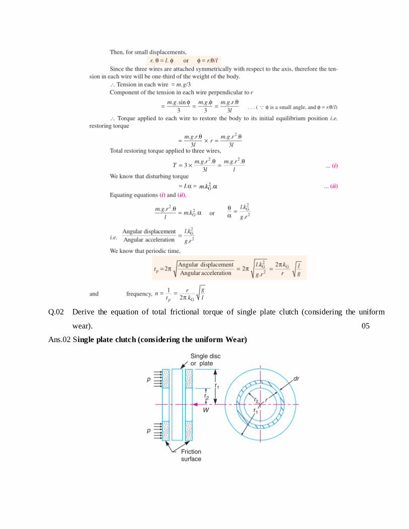
Q.02 Derive the equation of total frictional torque of single plate clutch (considering the uniform
wear). 05
Ans.02 Single plate clutch (considering the uniform Wear)

Or
Q.02 Explain the working of Centrifugal Clutch with neat sketch. 05
Ans.02 The centrifugal clutch consists of a number of shoes or friction pads arranged radially
symmetrical position inside the rim. It can slide along the guides integral with the boss on the driving

shaft. The shoes are held against boss by using a spring that exerts a radially inward force. As the inner
hub rotates, the weight of the shoe causes a radially outward force known as centrifugal force. This force
depends on the weight of the shoe and the speed at which it rotates.
At low speed, the centrifugal force also low, the shoes remain in the same position. As speed increases,
the centrifugal force also increases, when centrifugal force becomes equal to spring force the shoes start
floating. When the driver rotates fast enough the centrifugal force exceeds the spring force the shoes
moves outward. At a certain speed, it gets contact with the inner surface of the drum and torque is
transmitted. As the load increases, speed decreases; the shoes return to their original position and clutch
Gets disengaged.
Advantage
5. Simple and inexpensive and need little maintenance.
6. The centrifugal clutch is automatic any kind of control mechanism is not necessary.
7. They help to prevent the engine from stalling.
8. The engagement speed can precisely control by selecting spring.
Disadvantage
4. Loss of power due to friction and slipping.
5. This type of clutch not appropriate for the high amount of torque, the shoes will slip at the heavy
loaded condition.
6. They engage at full or near-full power, shoes get heated very quickly may cause overheating.
Q.03 Explain the working of Rope Brake Dynamometer & write down the formula of BHP. 05
Ans.03

Or
Q.03 In a Laboratory Experiment:-
Diameter of the flywheel (Drum) & Rope is 1.2 meter & 12.5 mm, Speed 200 rpm, Dead load on
the brake 600 N, spring balance reading 150 N. Calculate the brake power of the engine. 05
Ans.03
Q.04 Derive the Equation of Braking of Four wheels Vehicle when Brakes are applied to all the four
wheels. 05
Ans.04 Braking of Four wheels Vehicle

or
Q.04 The wheel base of a car is 3 meter & its C G is 1.2 meter ahead the rear axle & 0.75 m above the
ground level. The coefficient of friction between the wheels & the roads is 0.5 Determine the
maximum deceleration of the car when it moves on level roads if the braking force on all the
wheels is the same & no wheels slips occurs. 05
A.04 Solution