Railway Investigation Report R13E0142
35
RAILWAY INVESTIGATION REPORT R13E0142 NON–MAIN-TRACK DERAILMENT CANADIAN NATIONAL FREIGHT TRAIN M30151-18 MILE 57.25, EDSON SUBDIVISION GAINFORD, ALBERTA 19 OCTOBER 2013
Transcript of Railway Investigation Report R13E0142

RAILWAY INVESTIGATION REPORT R13E0142
NON–MAIN-TRACK DERAILMENT
CANADIAN NATIONAL FREIGHT TRAIN M30151-18
MILE 57.25, EDSON SUBDIVISION GAINFORD, ALBERTA
19 OCTOBER 2013

The Transportation Safety Board of Canada (TSB) investigated this occurrence for the purpose of advancing transportation safety. It is not the function of the Board to assign fault or determine civil or criminal liability.
Railway Investigation Report R13E0142
Non–Main-Track Derailment Canadian National Freight Train M30151-18 Mile 57.25, Edson Subdivision Gainford, Alberta 19 October 2013
Summary
On 19 October 2013, at 0100 Mountain Daylight Time, Canadian National freight train M30151-18, proceeding westward from Edmonton, Alberta, to Vancouver, British Columbia, derailed 13 cars, including 4 tank cars containing petroleum crude oil and 9 tank cars of liquefied petroleum gas (LPG), at Mile 57.25 of the Edson Subdivision, near Gainford, Alberta. Of the derailed LPG tank cars, 2 were breached and caught fire. A third LPG tank car released product from the safety valve and ignited. About 600 feet of track was destroyed. There were no injuries. A total of 106 homes in the vicinity of the derailment were evacuated. Le présent rapport est également disponible en français.

Railway Investigation Report R13E0142 | 1
Factual information
The accident
Canadian National (CN) freight train M30151-18 (the train) originated in Edmonton, Alberta, and was destined for Vancouver, British Columbia. The train comprised 2 locomotives, 98 loaded cars, 10 empty cars, and 26 residue cars. It weighed 13 704 tons and was 8692 feet long. The train was configured conventionally, with the 2 locomotives on the head end. The train crew consisted of a locomotive engineer and a conductor. Both crew members were positioned in the cab of the lead locomotive. They were qualified for their respective positions, met rest and fitness standards, and were familiar with the subdivision. At about 0100,1 while travelling on the Edson Subdivision, the train entered Gainford siding to meet eastbound train 416. It had proceeded about 3300 feet into the siding when a train-initiated emergency brake application occurred. When the train came to a stop, the crew looked back and observed flames from their train. The crew uncoupled the locomotives from the rest of the train and left the immediate area as the fire was increasing in intensity. The crew then made the necessary emergency broadcast and notified the rail traffic controller. There were no injuries. The accident occurred near the hamlet of Gainford, Alberta, in Parkland County, which is located about 86 km west of Edmonton (Figure 1).
Figure 1. Map of the derailment location (Source: Railway Association of Canada, Canadian Railway Atlas, with TSB annotations)
As a result, 13 tank cars derailed (cars 13 to 25). The first 4 derailed cars (cars 13 to 16) were loaded with petroleum crude oil (UN 1267). The following 9 derailed cars (cars 17 to 25) were loaded with liquefied petroleum gas (LPG)2 (UN 1075) (Figure 2). 1 All times are Mountain Daylight Time. 2 LPG is a gas liquefied by compression, composed of flammable hydrocarbons, principally propane
and butane. It is obtained as a by-product of the refining of petroleum or from natural gas.

2 | Transportation Safety Board of Canada
Between 14 October and 18 October, the cars involved in the derailment had undergone certified car inspections, with no exceptions noted. The train had been brake-tested on 18 October, prior to departing Edmonton. A review of the recent wheel impact information for the locomotives and for the first 25 cars determined that the impacts were well below condemnable limits. The wheel impact information for the preceding train through Gainford siding was reviewed, and no condemnable alarms were noted. Prior to the derailment, the occurrence train had passed wayside detector systems, including hot-wheel, hot-bearing and dragging equipment detectors, at Gainford (Mile 55.35) and Wabamun, Alberta (Mile 46.7). No alarms were noted at these wayside detectors.
Figure 2. Aerial view of derailment site
Weather
The weather at the time of the accident was 4°C, and the visibility was clear. Site examination
During the site examination (Figure 3), the following was determined:
· The point of derailment was in the curve at the east end of the Gainford siding, at Mile 57.25.

Railway Investigation Report R13E0142 | 3
· The first car to derail was the 16th car (UTLX 675762), which was the last tank car of petroleum crude oil before the LPG tank cars.
· There was a separation of about 1 car length between the first 2 derailed cars and the following 3 derailed cars.
· Of the 4 tank cars loaded with petroleum crude oil (cars 13 to 16), 3 were DOT 111A tank cars and 1 was a DOT 111S tank car.
· The first 5 derailed cars were positioned on their sides to the north of the siding track, onto the main line.
· All 9 derailed LPG cars (cars 17 to 25) were DOT 112J tank cars.
· The 17th car was derailed upright to the north and was positioned parallel to the siding.
· The 18th to 24th cars were derailed perpendicular to the siding and main track.
· The 25th car remained upright with the leading (west-end) truck derailed. A single-family home located immediately north of the derailment location on the north side of Highway 16 sustained damage from exposure to the extreme heat generated by the post-derailment fires and explosions.
Figure 3. Accident site diagram - Damage to UTLX 955375 (18th car ), UTLX 955459 (19th car) and CGTX 65449 (21st car)
4 | Transportation Safety Board of Canada
Recorded information
Data from the locomotive event recorder were downloaded and reviewed. The following was determined:
· At 0059:43, the train was entering the siding at 24 mph and had been in dynamic brake set-up for about 1 minute.
· The locomotive independent brake was being lightly applied (i.e., 10 psi) when a train-initiated emergency brake application occurred.
· The head end of the train continued for about 306 feet after the emergency application before coming to a stop.
Tank car damage
Damage to the derailed tank cars included the following:
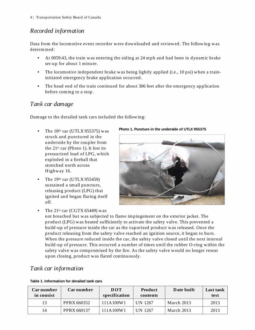
· The 18th car (UTLX 955375) was struck and punctured in the underside by the coupler from the 21st car (Photo 1). It lost its pressurized load of LPG, which exploded in a fireball that stretched north across Highway 16.
· The 19th car (UTLX 955459) sustained a small puncture, releasing product (LPG) that ignited and began flaring itself off.
· The 21st car (CGTX 65449) was not breached but was subjected to flame impingement on the exterior jacket. The product (LPG) was heated sufficiently to activate the safety valve. This prevented a build-up of pressure inside the car as the vaporized product was released. Once the product releasing from the safety valve reached an ignition source, it began to burn. When the pressure reduced inside the car, the safety valve closed until the next internal build-up of pressure. This occurred a number of times until the rubber O-ring within the safety valve was compromised by the fire. As the safety valve would no longer reseat upon closing, product was flared continuously.
Tank car information
Table 1. Information for derailed tank cars
Car number in consist
Car number DOT specification
Product contents
Date built Last tank test
13 PPRX 660352 111A100W1 UN 1267 March 2013 2013 14 PPRX 660137 111A100W1 UN 1267 March 2013 2013
Photo 1. Puncture in the underside of UTLX 955375

Railway Investigation Report R13E0142 | 5
15 PPRX 660295 111A100W1 UN 1267 March 2013 2013 16 UTLX 675762 111S100W1 UN 1267 August 2013 2013 17 PROX 32064 112J340W UN 1075 June 2002 2012 18 UTLX 955375 112J340W UN 1075 May 2010 2010 19 UTLX 955459 112J340W UN 1075 October 2010 2010 20 ACFX 220085 112J340W UN 1075 April 1996 2006 21 CGTX 65449 112J340W UN 1075 February 2007 2007 22 PROX 31854 112J340W UN 1075 March 2001 2011 23 PROX 33850 112J340W UN 1075 January 2006 2006 24 GATX 57167 112J340W UN 1075 January 1997 2006 25 TILX 303290 112J340W UN 1075 December 2007 2007
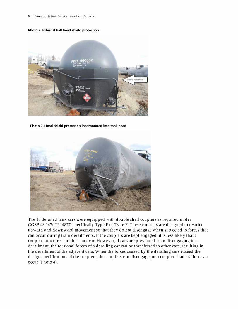
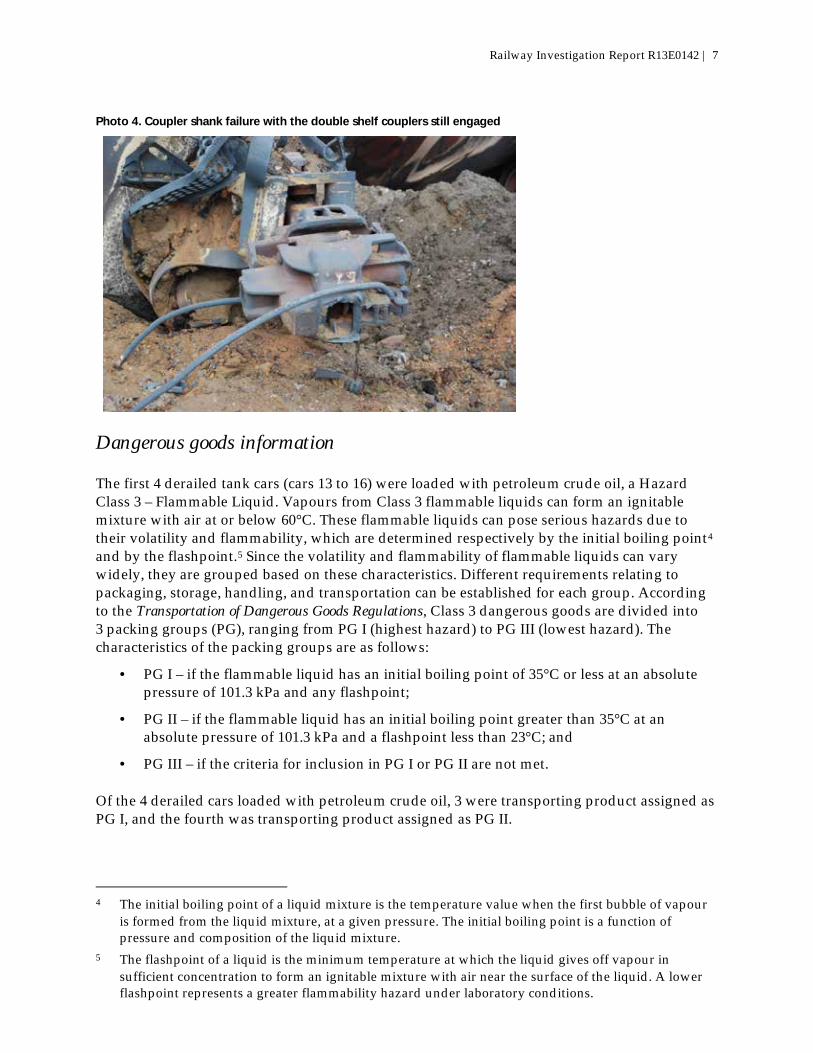
DOT 112J pressure tank cars are designed for the transportation of dangerous goods that are shipped under pressure (i.e., greater than 40 psia3 at 20°C), such as flammable liquids, flammable and non-flammable gases, and poisonous gases. The detailed specification (112J340W) identifies these cars as jacketed and thermally protected carbon steel pressure cars, designed for top loading and unloading, that have a design test pressure of 340 psi and a safety relief valve set at 280.5 psi. These cars have a tank wall thickness of 5/8 inch and a head thickness of 11/16 inch. The tank jacket incorporates a full head shield that is 1/2 inch thick. They have a capacity of 33 800 gallons. The 4 derailed cars transporting petroleum crude oil were designated as DOT 111A100W1 or DOT 111S100W1. The non-pressure tank cars were designed for general use. The tank thickness of the 111 tank cars was 7/16 inch. The 3 DOT 111A tank cars were equipped with external head shield protection (Photo 2). The DOT 111S tank car was equipped with the head shield incorporated into the design of the car (Photo 3). The 4 DOT 111 tank cars had been built to the revised Association of American Railroads (AAR) standard (CPC-1232 MSRP-C3, Chapter 2.7, effective October 2011), as outlined in Section C-III of the Association of American Railroads Manual of Standards and Recommended Practices. This tougher standard requires
· a thicker shell for puncture resistance;
· extra protective head shields at both ends of the tank car;
· additional protection for the top fittings; and
· higher flow capacity pressure release valves.
3 Pounds per square inch absolute (psia) is the pressure relative to a vacuum rather than the ambient
atmospheric pressure.
6 | Transportation Safety Board of Canada
Photo 2. External half head shield protection
Photo 3. Head shield protection incorporated into tank head
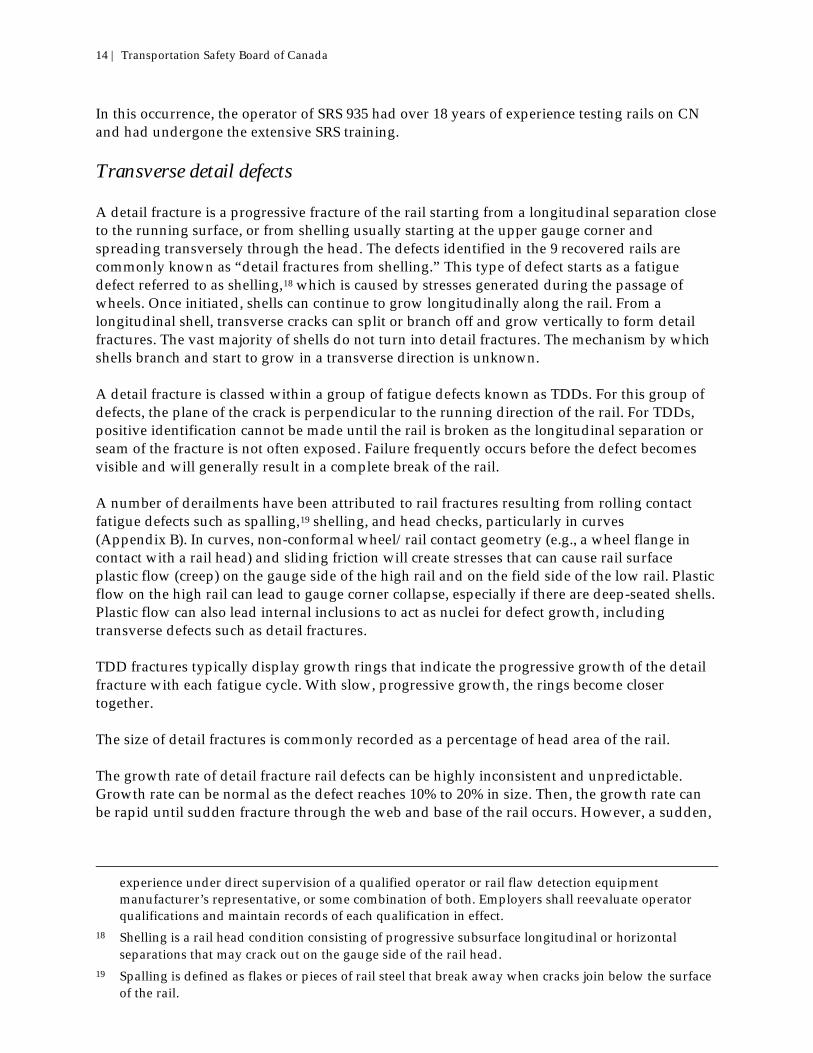
The 13 derailed tank cars were equipped with double shelf couplers as required under CGSB 43.147/TP14877, specifically Type E or Type F. These couplers are designed to restrict upward and downward movement so that they do not disengage when subjected to forces that can occur during train derailments. If the couplers are kept engaged, it is less likely that a coupler punctures another tank car. However, if cars are prevented from disengaging in a derailment, the torsional forces of a derailing car can be transferred to other cars, resulting in the derailment of the adjacent cars. When the forces caused by the derailing cars exceed the design specifications of the couplers, the couplers can disengage, or a coupler shank failure can occur (Photo 4).
Railway Investigation Report R13E0142 | 7
Photo 4. Coupler shank failure with the double shelf couplers still engaged
Dangerous goods information
The first 4 derailed tank cars (cars 13 to 16) were loaded with petroleum crude oil, a Hazard Class 3 – Flammable Liquid. Vapours from Class 3 flammable liquids can form an ignitable mixture with air at or below 60°C. These flammable liquids can pose serious hazards due to their volatility and flammability, which are determined respectively by the initial boiling point4 and by the flashpoint.5 Since the volatility and flammability of flammable liquids can vary widely, they are grouped based on these characteristics. Different requirements relating to packaging, storage, handling, and transportation can be established for each group. According to the Transportation of Dangerous Goods Regulations, Class 3 dangerous goods are divided into 3 packing groups (PG), ranging from PG I (highest hazard) to PG III (lowest hazard). The characteristics of the packing groups are as follows:
· PG I – if the flammable liquid has an initial boiling point of 35°C or less at an absolute pressure of 101.3 kPa and any flashpoint;
· PG II – if the flammable liquid has an initial boiling point greater than 35°C at an absolute pressure of 101.3 kPa and a flashpoint less than 23°C; and
· PG III – if the criteria for inclusion in PG I or PG II are not met.
Of the 4 derailed cars loaded with petroleum crude oil, 3 were transporting product assigned as PG I, and the fourth was transporting product assigned as PG II.
4 The initial boiling point of a liquid mixture is the temperature value when the first bubble of vapour
is formed from the liquid mixture, at a given pressure. The initial boiling point is a function of pressure and composition of the liquid mixture.
5 The flashpoint of a liquid is the minimum temperature at which the liquid gives off vapour in sufficient concentration to form an ignitable mixture with air near the surface of the liquid. A lower flashpoint represents a greater flammability hazard under laboratory conditions.

8 | Transportation Safety Board of Canada
The last 9 derailed tank cars (cars 17 to 25) were loaded with LPG (UN 1075), a flammable mixture of hydrocarbon gases most commonly called propane or butane. The boiling point for this product is below room temperature. Given that LPG will evaporate quickly at normal temperatures and pressures, it is usually stored and shipped in pressurized vessels. LPG is identified as a flammable gas with a hazard class of 2.1. LPG is heavier than air and will accumulate in low spots when released. In the event of a release, there are 2 main dangers: a possible explosion if the mixture of LPG and air is within the explosive limits and there is an ignition source, and suffocation due to LPG displacing air, resulting in a decrease in the available oxygen. The product is a colourless and odorless gas. An odorant is often mixed with LPG so that leaks can be more easily detected. Particulars of the track
The Edson Subdivision is part of CN’s main transcontinental route. This subdivision extends from Edmonton to Jasper, Alberta (Mile 235.7). Train movements on the Edson Subdivision are governed by the Centralized Traffic Control System, as authorized by the Canadian Rail Operating Rules, and supervised by a rail traffic controller located in Edmonton. Gainford siding is a 16 896-foot-long, bonded,6 signalled siding with a permissible speed of 25 mph. This siding is 1 of 7 signalled sidings on the Edson Subdivision. In 2013, the Edson Subdivision carried about 100 million gross tons (MGT) of traffic, with about 12 to 15 MGT travelling through Gainford siding. The east switch at Gainford siding (Mile 57.06) was a No. 12 turnout with a dual-control switch and fully-welded 136-pound rail, lag-bolted to wood ties. The point of derailment was determined to be within the siding in a 3.21° left-hand curve adjacent to Mile 57.25. The curve had an average superelevation7 of 0.54 inch. The balance speed for a 0.54-inch superelevation is 15.5 mph. As CN standards allow for a 2-inch imbalance in elevation, the allowable speed through this curve was 33.6 mph. In March 2013, the low rail between Mile 57.09 and Mile 57.32 had been changed out and replaced with new 136-pound TŽ8 intermediate strength rail. The high rail, which was 1974 and 1977 132-pound Algoma carbon rail, had 17 to 19 mm of head wear and 6 mm of flange wear. CN’s Engineering Track Standards, 1.0, Appendix A, Table 1(ii), indicates that the sum of the vertical and flange wear for 132-pound rail shall not exceed 24 mm. The high rail was scheduled for replacement in 2015. The rail rests on 14-inch and 16-inch double-shoulder tie plates secured to wood ties with spikes and anchored every second tie. Ballast was crushed rock in good condition. Safety ties9 were
6 A bonded or signalled siding is equipped with track circuits that are interconnected to the signal
system. Movements on signal indication into such a siding can be made at speeds higher than reduced speed, subject to railway special instructions.
7 The superelevation is the height, in inches, that the outer (high) rail of a curve is elevated above the inner (low) rail. It is intended to balance the effect of centrifugal force.
8 Třinecké železárny is a large steel making company in the Czech Republic. 9 Safety ties are ties inserted to break up clusters of defective ties.

Railway Investigation Report R13E0142 | 9
installed in the siding in 2011. The remaining ties had been adzed, and new plates were installed. Track inspection information
The Edson Subdivision main-line track through Gainford was Class 3. The Gainford siding track with a maximum speed of 25 mph was Class 2. According to section 2.4 – Visual Track Inspections of the Track Safety Rules (TSR) (Appendix C), the Gainford siding required twice-weekly visual inspections. Prior to the occurrence, the main-line track was receiving twice-weekly inspections. During these inspections, the siding track also received an adjacent visual inspection at the same time in accordance with section 2.4 of the TSR. The last traverse inspections10 of the siding conducted prior to the derailment occurred on 10, 13 and 17 October. The last adjacent visual inspections conducted prior to the derailment occurred on 17 and 18 October. Track geometry testing within the siding was conducted on 28 May and 30 August by CN’s TEST car.11 During these inspections, no defects were noted in the vicinity of the derailment site. Rail flaw detection testing
Ultrasonic technology provides a cost-effective and efficient way to test the tens of thousands of miles of rail in the North American rail network. Ultrasonic testing has proven to be a reliable and economical testing method, but as with all non-destructive test methods, there can be limitations. Rail testing is not an exact science. Skill, training, and experience are required to properly interpret the test data and identify rail defects. However, improvements to the defect-recognition software and the test-operator user interface have reduced the amount of human interpretation/intervention required to make a decision. CN employs Sperry Rail Service (SRS)12 to conduct its rail flaw testing. SRS’s rail flaw detection equipment utilizes fluid-filled roller search units that house and couple the transducers to the rail. Different transducer angles are combined to achieve the best inspection possible. Liquid couplant facilitates the transmission of ultrasonic energy from the transducers into the rail. SRS rail testing technology and processes are summarized in Appendix A. At SRS, rail flaw detection testing is generally conducted as follows:
· Rail flaw detection cars are operated with an assistant operator, who also drives the car, and a chief operator.
· The primary responsibility of the chief operator is the interpretation of the test data (i.e., identifying and recording rail defects). The chief operator currently monitors up to 30 ultrasonic test channels and up to 6 induction channels of test data while visually observing rail conditions and track features as the car moves. The work environment can be fast-paced with limited time to test in between regular train traffic. The available track time must therefore be maximized. Although railways seek to maximize miles
10 Visual inspections conducted while the inspection vehicle is travelling on the track being inspected 11 Canadian National track geometry TEST car 12 Sperry Rail Service is a contract service provider to the rail industry. It inspects railroad track for
subsurface flaws with a fleet of specialized test vehicles using proprietary technology and internally developed data management systems.

10 | Transportation Safety Board of Canada
tested each day, the chief operator is responsible for conducting the test and for maintaining the pace of the work at a manageable level. Since rail testing contracts are typically based upon hours worked, not miles tested, operators can take the time required for hand-testing and visual inspections, and if required, stop the car to rerun sections as deemed necessary.
· Defects must be large enough and perpendicular or nearly perpendicular to the sound-beam axis for an equipment response to be processed and presented to the operator for interpretation. Deficiencies in these areas can result and have resulted in defects not being properly identified or smaller defects being missed.
In general, the largest percentage of transverse-oriented flaws is detected in the head of the rail. While there is good ultrasonic coverage of the rail head, the current technology is less effective in detecting transverse-oriented flaws in the web and base of the rail. Transverse flaws located mid-web and lower are difficult to detect due to their orientation and location in the rail section. Longitudinal flaws can be detected in the head and web sections as well as in the base. Defects located outside the web section, such as in the weld collars and in the outer wings of the base, are non-detectable due to the limitations of the sound energy reaching those locations. In addition, the detectability of defects depends on the size and orientation of the transverse component and can be influenced by rail surface conditions such as the presence of grease or dirt on the rail head. Other factors such as head checking13 and internal shelling can also affect the test results. The American Railway Engineering and Maintenance-of-Way Association (AREMA) Manual for Railway Engineering, Chapter 4, section 4.3.2, presents a recommended minimum performance guideline for ultrasonic rail testing. This guideline can be used as the basis of an agreement between the rail testing operator and the railway for a minimum acceptable performance standard. The SRS/CN contract specifications were more stringent than the AREMA guideline, requiring even smaller defects to be found on a more frequent basis. The reliability ratio is used to measure testing performance and is defined as the percentage of actual in-track defects that can be expected to be located in a single test by a test car that is operated by an experienced operator in service over a typical mix of track conditions. Reliability ratios depend on size of defect and category of track. Given that 100% accuracy in testing is not possible, the performance guideline specifies the number of valid defects in track that are not reported or are otherwise not detected. AREMA testing performance standards specify a reliability ratio of 55% for detail fracture defects from shelling or head checking of 10% to 20% of cross-sectional head area. Detection of smaller cracks is not assured. The reliability ratio standard is 75% for detail fracture defects of 21% to 40% of cross-sectional head for Category II track. Category II track includes all sidings and track with tonnage of less than 3 MGT per year, and with train speeds of less than 40 mph. Gainford siding was Category II track. Category I track includes all main track with tonnage equal to or exceeding 3 MGT per year, or with train speeds equal to or exceeding 40 mph (Table 2).
13 Head checking are shallow hairline cracks that appear on the rail head, usually the gauge corner.

Railway Investigation Report R13E0142 | 11
Table 2. AREMA-recommended minimum performance guideline for rail testing: detail fracture from shelling or head check
Size (percentage of head
area fractured)
Reliability ratio (percentage of defects properly indicated as flaws in any single test)
Category I Category II 10%–20% 65% 55% 21%–40% 85% 75% 41%–80% 95% 85%
81%–100% 98% 95% Detail fractures are a common defect, and one of the more dangerous given that the only way to locate them before failure is through ultrasonic inspection. When rail surface is in reasonable condition, SRS’s detection reliability for transverse detail defects (TDD)14 has been 95% or greater. In 2013, SRS detected a total of 32 617 defects while testing 117 341 miles of track on CN track in Canada. A total of 14% (i.e., 4458) of these defects were TDDs. During the same period, CN reported 276 rail service failures, of which 20 (or 7%) were due to TDDs. CN tracks records of broken rails within 30 days of an ultrasonic test. Any in-service failures occurring within those 30 days are investigated, and successive inspections on a given track are compared to identify any defects missed. An operator who has not identified potential suspect locations that were present is given feedback and/or remedial training. In 2013, the reported TDD service failures accounted for 0.4% of all TDDs (SRS-detected + failed in service). SRS’s detection ratio for TDDs was 99.6%. Rail defect testing in Gainford siding
The Transport Canada–approved TSR, Subpart F, section 5.5, specifies that rail in sidings where track speed is 25 mph or greater should be inspected using rail flaw detection at least once a year. In 2013, rail flaw inspections on the Gainford siding were conducted on 24 January, 08 April, 17 July, and 28 August, exceeding the TSR and CN’s Engineering Track Standards requirements for inspection frequency.15 Rail flaw detection was conducted by SRS using rail defect inspection vehicles (i.e., SRS 951 and SRS 935). These vehicles are equipped with the latest ultrasonic technology, vision and induction testing technology, and operator analysis tools. Table 3 summarizes the rail defects identified in Gainford siding during the 2013 rail flaw detection tests.
14 See subsection titled Transverse Detail Defects. 15 Testing schedules are based on a combination of: requirements of the Track Safety Rules (TSR), million
gross tons (MGT), number and type of defects detected, rail weight, type of traffic and, to a certain extent, in-service failures.

12 | Transportation Safety Board of Canada
Table 3. Rail flaw detection results for Gainford siding
Test date Car number Defect Mile 24 January 951 Defective field weld 60.15
08 April 935 Crushed head 57.25 Rail end batter 57.24 Transverse detail defect 59.37
17 July 935 Defective field weld 58.55 Localized surface collapse 58.83
28 August 935 Rail end batter * 58.37 *A plug rail had been installed to remove this defect from track before the derailment. A review of the 28 August rail flaw detection results indicates that the ultrasonic probes, and the induction and vision systems on SRS 935 had been working to specification. The following occurred during the 28 August test:
· One rerun had to be conducted due to loss of expected response of the ultrasonic signal. There was no loss of expected response on the test rerun.
· Some high rail gauge surface conditions were noted within Gainford siding and confirmed by system-generated vision photos of the rail.
· Based on the vision photos, the operator attributed the system response to the rail fatigue conditions (Photo 5 and Photo 6). Since there had been no loss of expected response on the test rerun, the operator considered the test to be valid, and no further action was taken.16
Photo 5. Rail surface conditions
16 If the operator assigned to operate the rail defect detection equipment determines that, due to rail
surface conditions and or other reasons, a valid search for internal defects could not be made over a particular length of track, the test on that particular length of track cannot be considered as a search for internal defects. The section of track is then marked “No Test” (Appendix D).

Railway Investigation Report R13E0142 | 13
Photo 6. Rail surface conditions
· Approximately 190 feet west of a joint at Mile 57.21, elevated induction signals were recorded on the high rail, but without correlating ultrasonic signals. It was suspected that the induction thresholds may have been too high, resulting in a potential false positive for a defect. Given that the vision photos showed intermittent gauge surface conditions on the high rail, the operator attributed this system response to fatigue conditions at the gauge contact.
Operator training for rail defect testing
SRS operators will normally progress from the existing assistant operator/driver group. In addition, operators are recruited from schools and organizations involved in non-destructive testing. The training program for chief operator positions includes 32 modules of online pre-course training and 9 weeks of in-house training specific to SRS equipment and procedures. The in-house portion includes 360 hours of lectures, demonstrations, B-scan simulator training, and hand-testing laboratory training, plus general, practical and specific examinations. The course content meets the guidelines of the American Society for Nondestructive Testing Recommended Practice No. SNT-TC-1A. This training program is also in compliance with Federal Railroad Administration (FRA) regulations.17
17 The Federal Railroad Administration (FRA) issued revisions to the Track Safety Standards that came
into effect on 25 March 2014. Section 213.238 of the Code of Federal Regulations Title 49 (Part 213, Improving Rail Integrity), covers the qualification of detector car operators. The training, qualification and continuing evaluation of the employees are the responsibility of the employer of the detector car operator, and the new regulation states that a track owner shall not use a provider of rail-flaw detection that fails to comply with the new regulation. To be qualified, the operator shall be trained and have written authorization from his or her employer to conduct a valid search for internal rail defects utilizing the specific types of equipment for which he or she is authorized and qualified to operate. The operator must have a minimum of 160 hours of rail flaw detection
14 | Transportation Safety Board of Canada
In this occurrence, the operator of SRS 935 had over 18 years of experience testing rails on CN and had undergone the extensive SRS training. Transverse detail defects
A detail fracture is a progressive fracture of the rail starting from a longitudinal separation close to the running surface, or from shelling usually starting at the upper gauge corner and spreading transversely through the head. The defects identified in the 9 recovered rails are commonly known as “detail fractures from shelling.” This type of defect starts as a fatigue defect referred to as shelling,18 which is caused by stresses generated during the passage of wheels. Once initiated, shells can continue to grow longitudinally along the rail. From a longitudinal shell, transverse cracks can split or branch off and grow vertically to form detail fractures. The vast majority of shells do not turn into detail fractures. The mechanism by which shells branch and start to grow in a transverse direction is unknown. A detail fracture is classed within a group of fatigue defects known as TDDs. For this group of defects, the plane of the crack is perpendicular to the running direction of the rail. For TDDs, positive identification cannot be made until the rail is broken as the longitudinal separation or seam of the fracture is not often exposed. Failure frequently occurs before the defect becomes visible and will generally result in a complete break of the rail. A number of derailments have been attributed to rail fractures resulting from rolling contact fatigue defects such as spalling,19 shelling, and head checks, particularly in curves (Appendix B). In curves, non-conformal wheel/rail contact geometry (e.g., a wheel flange in contact with a rail head) and sliding friction will create stresses that can cause rail surface plastic flow (creep) on the gauge side of the high rail and on the field side of the low rail. Plastic flow on the high rail can lead to gauge corner collapse, especially if there are deep-seated shells. Plastic flow can also lead internal inclusions to act as nuclei for defect growth, including transverse defects such as detail fractures. TDD fractures typically display growth rings that indicate the progressive growth of the detail fracture with each fatigue cycle. With slow, progressive growth, the rings become closer together. The size of detail fractures is commonly recorded as a percentage of head area of the rail. The growth rate of detail fracture rail defects can be highly inconsistent and unpredictable. Growth rate can be normal as the defect reaches 10% to 20% in size. Then, the growth rate can be rapid until sudden fracture through the web and base of the rail occurs. However, a sudden,
experience under direct supervision of a qualified operator or rail flaw detection equipment manufacturer’s representative, or some combination of both. Employers shall reevaluate operator qualifications and maintain records of each qualification in effect.
18 Shelling is a rail head condition consisting of progressive subsurface longitudinal or horizontal separations that may crack out on the gauge side of the rail head.
19 Spalling is defined as flakes or pieces of rail steel that break away when cracks join below the surface of the rail.

Railway Investigation Report R13E0142 | 15
complete failure can occur in defects of any size.20 Transportation Technology Center, Inc. research, under joint sponsorship of the FRA and the AAR, has shown that the average growth rate of a detail fracture defect can exceed 5% of the cross-sectional area of the rail head for every 1 MGT of train traffic.21 Between 28 August (date of ultrasonic test) and 19 October (date of the derailment), approximately 2.3 MGT of traffic had travelled through Gainford siding. Defect growth from initiation to 10% of the rail cross-sectional head area occurs relatively slowly, but the growth rate tends to increase after 10%. Growth rate beyond 10% to 60% of the cross-sectional head area can be reasonably represented by a straight line.22, 23 Rapid defect growth rates can also be associated with rail where high-tensile residual stresses are present in the rail head and in continuous welded rail in lower temperature ranges where the rail is in high longitudinal tension. Rail life due to wear and fatigue
Increasing rail wear limits extends the life of a valuable asset, represents significant savings, and has been made possible with advances in clean steel technology that have made newer rails more resistant to wear and defect development. The wear limits apply to all rails, including older vintage rails. However, older rails are usually replaced due to fatigue defects before reaching the wear limit. Rail fatigue life24 depends on a number of factors, including accumulated tonnage, location (curve or tangent), cleanliness and grade of the steel, support conditions, lubrication, grinding, and residual stresses25 within the rail. Under optimal conditions and with proper maintenance, some rails can achieve a fatigue life of over 1 billion gross tons. CN has developed a Rail Defect Index (RDI) to help in the placement of cold-weather speed restrictions, the replacement of defective rail, and the cascading of used rail based on its prior defect history. The RDI analysis is a risk-based approach that assigns a severity number (from 1 to 10) to each defect. The severity number assigned is based on the defect type, the speed at which it is growing, and the ease of detectability, with fatigue defects having the highest
20 American Railway Engineering and Maintenance-of-Way Association (AREMA), Manual for Railway
Engineering, Chapter 4, 4-4-23. 21 Greg Garcia, et al, Transportation Technology Center, Inc. study concerning the development of
transverse-oriented detail fracture defects, “Flaw Characterization of Rail Service Failures,” Association of American Railroads (AAR) Report No. R–963. July 2003.
22 P. Clayton and Y.H. Tang, “Detail Fracture Growth Rates in Curved Track at the Facility for Accelerated Testing (FAST),” Residual Stress in Rails, Vol. 1, pp. 37–56, (The Netherlands: Kluwer Academic Publishers, 1992), p. 48. “Fatigue Defect Origination and Growth Experiment,” FRA ORD-91/18, 1991 Association of American Railroads-sponsored research at FAST.
23 D. Jeong, “Analytical Modelling of Rail Defects and Its Applications to Rail Defect Management,” U.S. Department of Transportation Research and Special Programs Administration, Volpe National Transportation Systems Center, Cambridge, Massachusetts, January 2003, p. 15.
24 Fatigue life is generally defined as the number of cycles to failure. In the railway industry, the measure of cycles is the accumulated tonnage on the rail.
25 Stresses left over from the manufacturing process and that occur with no external loading of the rail

16 | Transportation Safety Board of Canada
severity rating and wear defects having the lowest. Rail severity plots are used with the RDI program as analytical tools to help with decision making. Rail grinding
The rail head is ground periodically as a maintenance procedure to control surface damage on the rail, including corrugations, head checking, and spalling. Rail grinding is also used to adjust the contact geometry between the wheel and the rail by ensuring the correct rail head profile. In doing so, the wheel/rail contact position can be moved across the rail head to a location that minimizes contact stresses. By adjusting the contact geometry, the initiation of deep-seated shell defects such as detail fractures26 at the upper gauge corner can be prevented. Rail grinding slows the initiation and growth of small, deep-seated shell defects. CN considers rail grinding to be the primary defence against internal defect initiation and propagation. For preventive grinding, curves greater than 3° should be ground every 15 to 25 MGT.27 CN Standard Practice Circular 3709, Rail Grinding with Self-Propelled Grinding Machines, indicates that the grinding profiles and grinding frequency will be as specified by the chief engineer. This standard was intended for main-line rails but had not been expanded to include sidings. While the main track on the Edson Subdivision main line was being ground regularly, there is no record of when Gainford siding rail was last ground. Rail lubrication
Rail lubrication (i.e., friction management) is the process of controlling the friction properties of the wheel/rail contact at the wheel flange and the top of the rail. Wheel and rail wear, contact stresses, lateral forces, and rolling resistance in both curved and tangent track are reduced with rail lubrication. An added benefit is reduced fuel consumption. CN’s lubrication program uses wayside flange and top-of-rail lubricator systems. The lubricators use non-contact, rail-mounted sensors that detect the passing of wheels to signal an electric motor to dispense lubricant. Control-box settings can be adjusted to regulate the volume of lubricant dispensed based on the number of wheels travelling through the site, minimizing lubricant waste and the potential for wheel slips and train stalls. There are no lubricators in Gainford siding. The nearest flange lubricators to Gainford siding are located on the main line at Mile 56.0 and Mile 62.3. Neither grinding nor lubrication alone is enough to properly manage the wheel/rail interface. However, a preventive grinding program, gauge-face lubrication, and top-of-rail friction management can work together to prevent defect development and extend rail life.28
26 “Controlling Deep-Seated Shells on CPR,” Railway Track & Structures, June 2006. 27 A.M. Zarembski, The Art and Science of Rail Grinding. (Omaha, Nebraska: Simmons-Boardman Books
Inc., August 2005, pp. 253–258 and pp. 284–288), p. 262. 28 “Grinding, Friction Management, Handling HAL Maintenance of Way Headaches,” Railway Track
& Structures, July 2004.

Railway Investigation Report R13E0142 | 17
Laboratory analysis of recovered rails
Approximately 565 feet of rail, nearly the entire length of the curve high rail, was recovered. The rail was examined on site, and 16 pieces of rail, marked TSB-1 to TSB-16, were sent to Exova’s materials testing laboratory in Montréal, Quebec, for detailed analysis.29 Non-destructive magnetic particle inspection and ultrasonic testing were performed on the rail. The test results are summarized in Table 4.
Table 4. Summary of rail test results
Specimen number
Worn rail head area (inches²)
Fatigue crack area
including rapid growth
(inches²)
Percentage of worn rail
head area for fatigue crack
area
Rapid growth area
(inches²)
Percentage of worn rail
head area for rapid growth
area TSB-1 EE FC 3.03 0.433 14.3 0.1555 5.1 TSB-1 embedded FC 3.03 0.932 30.8 0.1194 3.9
TSB-1 WE FC 3.02 0.439 14.5 None N/A TSB-2 EE FC 3.02 0.231 7.6 None N/A TSB-3 EE FC 3.15 0.345 10.9 None N/A TSB-3 embedded FC 3.15 0.040 1.3 None N/A
TSB-3 embedded FC 3.15 0.049 1.5 None N/A
TSB-3 WE Overload fracture TSB-4 EE FC 3.31 0.814 24.6 0.1876 5.7 TSB-4 WE FC 3.14 0.373 11.9 0.1721 5.5 TSB-5 EE FC 2.90 0.770 26.5 None N/A TSB-5 embedded FC 2.94 0.445 15.1 0.1485 5.1
TSB-5 WE FC 3.13 0.440 14.0 None N/A TSB-6 EE FC 3.13 0.446 14.3 None N/A TSB-7 WE FC 3.04 0.455 15.0 None N/A TSB-8 EE FC 3.13 0.213 6.8 None N/A TSB-9 WE FC 2.85 0.762 26.7 None N/A TSB-10 Overload fracture TSB-11 Overload fracture TSB-12 Overload fracture TSB-13 Overload fracture 29 Metalurgical analysis was performed by Exova on behalf of Canadian National and in consultation
with Transportation Safety Board technical staff.
18 | Transportation Safety Board of Canada
TSB-14 Overload fracture TSB-15 Overload fracture TSB-16 Overload fracture Notes: EE = East End, WE = West End, FC = Fatigue Crack Head area of new 132-pound rail = 4.53 inches² TSB-1 EE matches TSB-4 WE, TSB-5 EE matches TSB-9 WE, TSB-6 EE matches TSB-7 WE
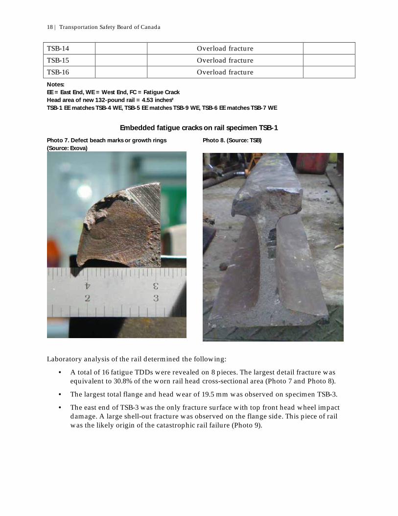
Embedded fatigue cracks on rail specimen TSB-1
Photo 7. Defect beach marks or growth rings (Source: Exova)
Photo 8. (Source: TSB)
Laboratory analysis of the rail determined the following:
· A total of 16 fatigue TDDs were revealed on 8 pieces. The largest detail fracture was equivalent to 30.8% of the worn rail head cross-sectional area (Photo 7 and Photo 8).
· The largest total flange and head wear of 19.5 mm was observed on specimen TSB-3.
· The east end of TSB-3 was the only fracture surface with top front head wheel impact damage. A large shell-out fracture was observed on the flange side. This piece of rail was the likely origin of the catastrophic rail failure (Photo 9).

Railway Investigation Report R13E0142 | 19
· The presence of pre-existing internal transverse defects caused the rails to break.
· The transverse defects initiated in areas of shelling that resulted from long-term heavy traffic levels.
· Rail surface damage such as shelling and cracks seem to have significantly impeded the detection of the defects, reducing the performance of ultrasonic equipment used to detect internal defects.
Other similar occurrences
On 03 November 2013, while departing Peers siding at Mile 109.60 of the Edson Subdivision, eastbound train 34851-01 experienced an undesired emergency brake application. After the train came to a stop, it was determined that 12 loaded lumber cars and 1 tank car—PROX 91468, carrying a load of sulfur dioxide—had derailed upright, fouling the main track. There were no injuries or product leaks (TSB occurrence R13E0153). Peers siding is 1 of 7, 25-mph sidings on the Edson Subdivision. During site examination, a piece of 1996 Bethlehem rail with a TDD was identified, approximately 12 inches away from a thermite weld (Photo 10). The rail had 18-mm head wear and 5-mm flange wear. Another TDD was found nearby in a separate piece of the same rail. Both rail pieces were battered, indicating that the rail had broken and remained in track until the passage of wheels broke more pieces out. The rail was from a plug rail30 located in the south (high) rail of the siding near the tangent-to-spiral point of a curve leading to the east switch. The parent rail was 1987 Sydney carbon steel with 18-mm head loss and 1-mm flange wear. All of the rail involved was 136 pounds with little shelling and gauge corner cracking. Peers siding had been tested for rail flaws on 26 August with no defects detected. Review of the SRS test, which was performed with the same operator and truck that had tested Gainford siding 2 days later, revealed indications of near-surface ultrasonic and induction responses. The operator interpreted the cause of these responses to be surface fatigue on the centre/gauge portion of the rail head. There was no indication on the B-scan31 test tape of a TDD. 30 A short piece of rail, i.e. 10 feet, normally installed subsequent to the occurrence of a broken rail. Plug
rails are selected on the basis of the wear characteristics of the rails on either side of the broken rail. They are normally bolted in place as part of an emergency repair, then eventually welded in place to complete the repair.
31 A-scan and B-scan refer to the way testing information is displayed to the operator. Most of SRS’s fleet, including SRS 951 and SRS 935, were equipped with the B-scan system. The B-scan display
Photo 9. Wheel impact damage on rail specimen TSB–3 (Source: Exova)

20 | Transportation Safety Board of Canada
See Appendix B for other similar occurrences.
Photo 10. Transverse detail defect (TDD) in gauge corner of high rail (east end of plug [yellow arrow]) in Peers siding (note location of thermite weld [red arrow])
Emergency response
The Parkland County Fire Department was on scene shortly after the occurrence. In conjunction with CN, a unified incident command was set up. The hot zone, an incident command post, and an emergency operations centre were established. The Royal Canadian Mounted Police provided assistance to restrict access to the site. Traffic on Highway 16 was detoured in both directions to secondary roads. Anyone entering the protected zone was required to sign in and out at a checkpoint. An evacuation of residents commenced within 1 hour of the derailment and was completed at 0305 on 19 October. A total of 106 homes in the vicinity of the derailment were evacuated. The total number of evacuees was 138. The evacuation ended after 4 days. In addition to the Parkland County Fire Department, the Royal Canadian Mounted Police and CN, other agencies on site included the TSB, Transport Canada, Alberta Transportation, and Alberta Environment and Sustainable Resource Development.
allows the chief operator to analyze the data more efficiently and with increased accuracy as compared with the A-scan system. All ultrasonic and induction channels are monitored on the B-scan display, and the data from the inspection equipment is processed and made available to the chief operator inside the car via display monitors.
Railway Investigation Report R13E0142 | 21
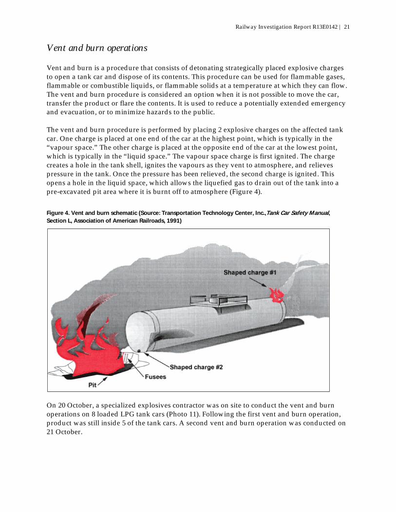
Vent and burn operations
Vent and burn is a procedure that consists of detonating strategically placed explosive charges to open a tank car and dispose of its contents. This procedure can be used for flammable gases, flammable or combustible liquids, or flammable solids at a temperature at which they can flow. The vent and burn procedure is considered an option when it is not possible to move the car, transfer the product or flare the contents. It is used to reduce a potentially extended emergency and evacuation, or to minimize hazards to the public. The vent and burn procedure is performed by placing 2 explosive charges on the affected tank car. One charge is placed at one end of the car at the highest point, which is typically in the “vapour space.” The other charge is placed at the opposite end of the car at the lowest point, which is typically in the “liquid space.” The vapour space charge is first ignited. The charge creates a hole in the tank shell, ignites the vapours as they vent to atmosphere, and relieves pressure in the tank. Once the pressure has been relieved, the second charge is ignited. This opens a hole in the liquid space, which allows the liquefied gas to drain out of the tank into a pre-excavated pit area where it is burnt off to atmosphere (Figure 4).
Figure 4. Vent and burn schematic (Source: Transportation Technology Center, Inc.,Tank Car Safety Manual, Section L, Association of American Railroads, 1991)
On 20 October, a specialized explosives contractor was on site to conduct the vent and burn operations on 8 loaded LPG tank cars (Photo 11). Following the first vent and burn operation, product was still inside 5 of the tank cars. A second vent and burn operation was conducted on 21 October.

22 | Transportation Safety Board of Canada
Photo 11. Initial vent and burn operation
The second vent and burn operation was successful on all of the remaining cars but 1, where only the vapour space was penetrated. However, the liquid space was not penetrated, and the ignited vapours burned through the vapour hole. Responders then pumped water into the liquid line using a fire truck, forcing the burning product up and out of the vapour hole in liquid form. This process lasted all night. Once water began flowing from the vapour hole shortly after daybreak, the fire was extinguished. Following this operation, wrecking operations and main-line track restoration work commenced.

Railway Investigation Report R13E0142 | 23
Analysis
Neither the condition of the rolling stock nor the manner in which the train was operated was considered contributory to this accident. The analysis will focus on the rail, including defects, rail management, inspection, and testing practices. The accident
The train derailed when 1 or more rail breaks occurred in the high rail as the train traversed the curve at the east end of Gainford siding. During the derailment, several other rails broke in the vicinity of the point of derailment. The fragmentation of the rail was due to the presence of numerous transverse defects along the length of the high rail in the curve. The transverse defects initiated in areas of shelling that had resulted from the relatively high traffic density and traffic loading within Gainford siding. The maximum operating speed for Gainford siding was 25 mph. However, with a balance speed of 15.5 mph through the curve, higher stresses were present at wheel/rail interface (i.e., the gauge face of the high rail). These higher stresses were conducive to the formation of shells and fatigue cracks along the gauge face of the high rail. Critical size for 1 of the transverse defects was reached when the remaining rail head area, which was at or near its wear limits, could no longer support the load, resulting in the sudden and complete failure of the rail. Although a rail flaw detection test had been performed (i.e., less than 2 months before), the presence of head checking and shelling in the area of the rail running surface had adversely affected the ability of the system to locate the tranverse detail defects (TDDs). Rail replacement in curves
The low rail in the curve had been relaid in March 2013 with new 136-pound rail. The new rail had a higher vertical height than the previously worn low rail. With no change to the high rail, which was near its wear limit of 24 mm (i.e., combined vertical and flange wear), the curve’s superelevation was reduced. Although the superelevation still met Canadian National (CN) standards, the balance speed was only 15.5 mph, less than the maximum operating speed of 25 mph. When trains travelled through the curve at greater than the balance speed, more stress was placed on the gauge face of the high rail, promoting the formation of shells and fatigue cracks. If rail on only one side of a curve is replaced with rail of a different height, the curve’s superelevation and balance speed will be altered, increasing the risk of higher stresses and damage to the other rail. Removal of rail surface defects prior to ultrasonic testing
Ultrasonic rail testing can be unreliable when the rail surface condition is poor or contaminated. In these situations, the ultrasonic signal may not adequately penetrate the rail surface, resulting in the masking of developing internal rail defects, thereby increasing the risk of a broken rail derailment. In this occurrence, the existence and depth of head checking and shelling in the central region of the running surface had adversely affected the capability of the ultrasonic signals to penetrate the steel to detect the TDDs.

24 | Transportation Safety Board of Canada
CN considers rail grinding to be the primary defence against internal defect initiation and propagation. For preventive grinding on main-line track, railway standard practice dictates that curves greater than 3° should be ground every 15 to 25 million gross tons (MGT), and that the grinding profiles and frequency will be as specified by the chief engineer. While this standard was originally intended for main-line rails and not for occasionally used, slow-speed sidings, the higher speeds and heavier used signalled sidings of the Edson Subdivision may warrant consideration for a more robust grinding program. The grinding program would remove rail surface defects to maximize the effectiveness of ultrasonic inspection technology. If surface defects on rails are not removed prior to ultrasonic rail flaw detection, there is a risk that internal rail defects will remain undetected, leading to broken rails and derailments. Rail fatigue life
Rail fatigue life depends on a number of factors, including accumulated tonnage, location (curve or tangent), cleanliness of steel, support conditions, grade of steel, and residual stresses within the rail. Under optimal conditions, certain rails can achieve a fatigue life of over 1 billion gross tons. In this occurrence, the 1974 and 1977 vintage rail on the high rail in the derailment curve was at or near CN’s wear limits. Although the total accumulated tonnage is unknown, the presence of TDDs throughout the rail indicates that the rail was at or near its fatigue limit. Rail fatigue life was monitored through rail testing and the assessment of the number and types of rail defects detected. Despite increased rail testing at Gainford siding, the numerous transverse defects were not detected. Crashworthiness of tank cars
The 4 DOT 111 tank cars involved in this occurrence (cars 13 to 16) rolled onto their sides to the north of the siding, coming to rest on top of the main track. It is likely that the 16th car was the first to derail. Due in part to the double shelf couplers, torsional forces acted upon the 3 cars ahead, causing them to derail. All 4 DOT 111 tank cars came to rest ahead of the main derailment location and were not struck by other derailing cars or directly subjected to damage from the fire and explosions that ensued. Given the longitudinal alignment of these cars as they rolled over onto the main track, the absence of secondary impacts, and the absence of exposure to fire and explosions from subsequent derailing cars, the 4 DOT 111 tank cars built to CPC-1232 standards were not heavily damaged in the derailment. The DOT 112J tanks car involved in this occurrence failed when they were struck by equipment from other derailed cars. Car 18, UTLX 955375, had rolled onto its side perpendicular to the direction of travel. Cars 19 and 20 avoided contacting UTLX 955375, but car 21, CGTX 65449, separated from car 20, continued to travel in a direct line, and struck the bottom of UTLX 955375 with its coupler near the centre of the car, compromising the jacket and the tank shell. This resulted in a rapid release of liquefied petroleum gas (LPG), which exploded. DOT 112J tank cars are designed to carry pressurized products such as LPG. Although they have extra protection on their ends, they have limited side protection (e.g., jacket). In this case, a coupler punctured the side of the DOT 112J car, resulting in the rapid release and explosion of the product. While double shelf couplers are designed to keep derailed tank cars coupled

Railway Investigation Report R13E0142 | 25
together, and tank car ends have been strengthened to withstand end impacts, tank car bodies are vulnerable to side impacts when derailed cars come apart. Incident response
A unified incident command structure was established, which included all responding jurisdictions and agencies. This command structure facilitated the rapid mobilization and efficient and effective use of resources. The evacuation was conducted in an effective manner. Appropriate and effective measures were taken to protect the site and ensure public safety immediately following the derailment.

26 | Transportation Safety Board of Canada
Findings
Findings as to causes and contributing factors
1. The train derailed when 1 or more rail breaks occurred in the high rail as the train traversed the curve at the east end of Gainford siding.
2. The fragmentation of the rail was due to the presence of numerous transverse defects along the length of the high rail in the curve. The transverse defects initiated in areas of shelling that resulted from high traffic density and loading.
3. With a balance speed of 15.5 mph through the curve, which had a maximum speed of 25 mph, higher stresses were present at wheel/rail interface (i.e., the gauge face of the high rail). These higher stresses were conducive to the formation of shells and fatigue cracks along the gauge face of the high rail.
4. Critical size for 1 of the transverse defects was reached when the remaining rail head area, which was at or near its wear limits, could no longer support the load, resulting in the sudden and complete failure of the rail.
5. Although a rail flaw detection test had been performed less than 2 months before, the presence of head checking and shelling in the area of the rail running surface had adversely affected the ability of the system to detect the transverse defects.
Findings as to risk
1. If rail on only 1 side of a curve is replaced with rail of a different height, the curve’s superelevation and balance speed will be altered, increasing the risk of higher stresses and damage to the other rail.
2. If surface defects on rails are not removed prior to ultrasonic rail flaw detection, there is a risk that internal rail defects will remain undetected, leading to broken rails and derailments.
Other findings
1. Despite increased rail testing at Gainford siding, the numerous transverse defects were not detected.
2. While double shelf couplers are designed to keep derailed tank cars coupled together, and tank car ends have been strengthened to withstand end impacts, tank car bodies are vulnerable to side impacts when derailed cars come apart.
3. Appropriate and effective measures were taken to protect the site and ensure public safety immediately following the derailment.

Railway Investigation Report R13E0142 | 27
4. Given the longitudinal alignment of the 4 DOT 111 tank cars as they rolled over onto the main track, the absence of secondary impacts, and the absence of exposure to fire and explosion from subsequent derailing cars, the DOT 111 tank cars built to CPC-1232 standards were not heavily damaged in the derailment.

28 | Transportation Safety Board of Canada
Safety action
Safety action taken
Following the derailment, Canadian National (CN) conducted walking inspections and rail flaw detection re-testing of all 25 mph sidings. Until the sidings had been re-tested, speed was reduced from 25 mph to 15 mph. The walking inspection was done to identify and develop a replacement program for rail with head checking surface conditions or spalling and more than 19 mm of head wear. Gainford siding was walked on 24 October. CN has commenced a program for rail grinding on high-speed sidings such as Gainford. This report concludes the Transportation Safety Board’s investigation into this occurrence. The Board authorized the release of this report on 28 January 2015. It was first released on 24 February 2015.
Correction The report released on 24 February 2015 stated, at the beginning of the second sentence in the second paragraph under the heading Crashworthiness of tank cars, “Car 19 avoided contacting UTLX 955375, but car 20, CGTX 65449, separated from car 19, continued to travel in a direct line and struck the bottom of UTLX 955375”. This has been corrected to say, “Cars 19 and 20 avoided contacting UTLX 955375, but car 21, CGTX 65449, separated from car 20, continued to travel in a direct line, and struck the bottom of UTLX 955375”. The corrected version of the report was released on 26 February 2015.
Visit the Transportation Safety Board’s website (www.bst-tsb.gc.ca) for information about the Transportation Safety Board and its products and services. You will also find the Watchlist, which identifies the transportation safety issues that pose the greatest risk to Canadians. In each case, the TSB has found that actions taken to date are inadequate, and that industry and regulators need to take additional concrete measures to eliminate the risks.

Railway Investigation Report R13E0142 | 29
Appendices
Appendix A – Sperry Rail Service – Rail flaw detection
Sperry Rail Service (SRS) rail flaw detector cars are configured with a test carriage, which is equipped with 12 transducers per rail (UX6 x 2). Of the 12 transducers, there are 2 zero-degree transducers, 1 forward-looking transducer, 1 reverse-looking transducer nominally aligned at 45°, 6 70° transducers, and 2 “side-looker” transducers. The transducers are directed and focused across the rail head cross-section to detect vertical separations in the rail head while travelling longitudinally along the rail.
Figure 4. (Source: Sperry Rail Service)
SRS’s latest upgrade to its ultrasonic technology is called X-Fire. X-Fire includes a third roller search unit wheel that is used for detecting transverse defects, which are difficult to find with the standard technology. These obliquely angled probes can locate transverse defects, even when gauge corner fatigue conditions are present. The X-Fire wheel contains 3 transducers per rail consisting of a zero-degree and a forward- and a reverse-facing X-Fire transducer. The advancement in probe arrays such as the X-Fire has resulted in improved cross-sectional coverage of the rail head. Other operational features of the SRS rail flaw detector car include the following:

30 | Transportation Safety Board of Canada
· The B-scan display allows the chief operator to analyze the data more efficiently and with increased accuracy. The data from the inspection equipment are processed and fed to the operator inside the car via display monitors. All the ultrasonic and induction channels are monitored on the B-scan display.
· The operator identifies normal track features such as joints, welds, switch components and crossings as part of the test record.
· If the operator considers an indication to be suspect, the test vehicle is stopped and backs up to the point where the indication was produced. The operator then gets out and hand-tests the rail with a hand-held ultrasonic test instrument. If a defect is confirmed by the hand test, it is marked, and a railroad work crew following the SRS car changes the rail or otherwise protects it.
· In addition to the ultrasonic method, SRS also employs electromagnetic (induction) technology. In the past, induction equipment was too large to mount on hi-rail vehicles, but SRS has developed an induction system that operates on a hi-rail platform. Today, 60% of SRS’s fleet is equipped with induction technology. Both ultrasonic only or ultrasonic/induction technology in normal operation will typically test in the range of 5 to 20 mph, depending on the environment and condition of the track.
· SRS has also advanced visual inspection with the addition of its vision and joint bar crack detection system. The vision system takes a picture of the rail whenever a system-generated response is presented to the test operator. This helps the operator better understand the attributing cause of the response, with the ability to examine associated conditions on the fly. This technology helps get more miles tested, with the advantage of not having to back up to observe associated conditions and/or track features that produced a response, more commonly referred to as a non-productive stop. The photos are taken from the gauge side only, angled toward the top of the rail head.

Railway Investigation Report R13E0142 | 31
Appendix B – Other similar occurrences
Since 2005, the Transportation Safety Board of Canada has investigated a number of derailments involving rail breaks due to undetected rail defects. These occurrences involved situations when rail flaw testing had been conducted shortly before the accident or when test results had been affected by poor rail surface conditions. The investigations include:
· R11C0118 – Main-track train derailment near Alix Junction, Alberta. On 21 October 2011, at approximately 0935 Mountain Daylight Time, Canadian National (CN) freight train Q11531-18, proceeding southward from Mirror, Alberta, to Calgary, Alberta, derailed 7 cars (13 car bodies) at Mile 13.2 of the Three Hills Subdivision, near Alix Junction. The derailed cars were carrying containers loaded with a variety of products, including some dangerous goods. Approximately 900 litres of phosphoric acid (cleaning products) were released. There were no injuries.
· R10C0086 – Main-track train derailment near Airdrie, Alberta. On 03 August 2010, at 0643 Mountain Daylight Time, Canadian Pacific Railway (CPR) freight train 2-269-02, proceeding southward from Red Deer, Alberta, to Calgary, Alberta, derailed 32 cars at Mile 21.4 of the Red Deer Subdivision. The derailed cars included 12 pressure tank cars containing anhydrous ammonia (UN 1005). No product was lost and there were no injuries.
· R09Q0047 – Main-track derailment near Saint-Tite, Quebec. On 21 November 2009, at 2046 Eastern Standard Time, CN train M-365-21-21 derailed 10 cars (5 loaded and 5 empty) on the railway bridge across des Envies River at Mile 6.53 of the Lac-St-Jean Subdivision. No dangerous goods were released and there were no injuries.
· R08C0164 – Main-track train derailment near Burdett, Alberta. On 30 November 2008, at 1604 Mountain Standard Time, CPR freight train 356-196, proceeding eastward from Lethbridge, Alberta, to Bellcott, Alberta, derailed 18 empty covered hopper cars at Mile 45.62 of the Taber Subdivision. No dangerous goods were involved and there were no injuries.
· R05E0059 – Main-track derailment near Wabamun, Alberta. On 03 August 2005, at 0509 Mountain Daylight Time, CN freight train M30351-03, proceeding westward from Edmonton, Alberta, to Vancouver, British Columbia, derailed 43 cars, including 25 loaded cars of Bunker C (heavy fuel oil), 1 loaded car of pole treating oil, and 1 loaded car of toluene (UN 1294), at Mile 49.4 of the Edson Subdivision. Approximately 700 000 litres of Bunker C and 88 000 litres of pole treating oil were spilled.

32 | Transportation Safety Board of Canada
Appendix C – Transport Canada, Track Safety Rules, Subpart F, Section 2.4 – Visual Track Inspections
(a) Unless otherwise specified, each Visual Track Inspection must be made on foot or by riding over the track in a vehicle at a speed that allows the person making the inspection to visually inspect and evaluate the track for compliance to the TSR.
(b) The speed of the vehicle must not be more than 5 mph when traversing railway crossings, turnouts or special trackwork.
(c) Mechanical, electrical and other track inspection devices may be used to supplement Visual track inspections.
(d) When inspecting track, an inspector may inspect up to two tracks at one time provided that: (i) The inspector’s visibility remains unobstructed by any cause and that the
second track is not centered more than 30 ft (9.144m) from the track upon which the inspector is traversing.
(ii) Each track that requires weekly or more frequent inspection must be traversed by the vehicle or inspected on foot on at least once every two weeks, and each siding and crossover must be traversed by the vehicle or inspected on foot at least once every month.
(e) All track except Yard Track and Inactive Track must be visually inspected at the minimum frequency specified in the following table:
Track
Designated Minimum Visual Track Inspection Frequency Table Class of Track Annual Tonnage (MGT)
< 5 MGT 5 – 15 MGT > 15 MGT Class 1 Monthly Twice Monthly Weekly Class 2 Weekly Twice Weekly Twice Weekly Class 3 Weekly Twice Weekly Twice Weekly
Class 4 & 5 Twice Weekly Twice Weekly Twice Weekly
And, (i) In the case of Class 1 track where passenger trains are operated, track
must be inspected weekly or before use of passenger traffic if the track is used less than once per week.
(ii) In the case of Class 2 and 3 track, where passenger trains are operated, track must be inspected at least twice weekly or before use of the passenger traffic.

Railway Investigation Report R13E0142 | 33
Appendix D – Transport Canada, Track Safety Rules, Subpart F, Section 5.8 – Missed Segment of Rail Flaw Inspection
(a) If the operator assigned to operate the rail defect detection equipment determines that, due to rail surface condition and or other reasons, a valid search for internal defects could not be made over a particular length of track, the test on that particular length of track cannot be considered as a search for internal defects under this section.
(b) If a valid search for internal defects cannot be conducted for reasons described in a), the railway company must, before the expiration of time or tonnage limits (i) Conduct a valid search for internal defects, or (ii) Reduce class of track to bring the track into compliance until such time as
a valid search for internal defects can be made, or (iii) Remove the rail from service.