Railway gate cct project report-Diploma Project
69
DEPARTMENT OF ELECTRONIC’S & COMMN. ENGG. NARNAUL-HARYANA-123002 PROJECT REPORT ON “ “ RAILWAY ACCIDENT RAILWAY ACCIDENT PREVENTER” PREVENTER” SESSION 2006 SUBMITTED BY:- Anamika Ranjna Rawat Subhash Kumar Yadav Swaita Ghawana Yogesh Kumar
-
Upload
subhash-kumar-yadav -
Category
Education
-
view
145 -
download
1
Transcript of Railway gate cct project report-Diploma Project

DEPARTMENT OF ELECTRONIC’S & COMMN. ENGG.
NARNAUL-HARYANA-123002
PROJECT REPORT ON
““RAILWAY ACCIDENTRAILWAY ACCIDENT PREVENTER”PREVENTER”
SESSION 2006
SUBMITTED BY:-Anamika Ranjna Rawat
Subhash Kumar YadavSwaita Ghawana Yogesh Kumar
UNDER GUIDANCE OF:-MR. MADHU GOPINATH
PIC MICROCONTROLLER BASED TRAINPIC MICROCONTROLLER BASED TRAIN ACCIDENT PREVENTION SYSTEMACCIDENT PREVENTION SYSTEM
It has the following railway accident features:-
1. Railway gate automatic opening and closing.
2. Avoidance of collision of train.
3. Presentation of accidents due to breaking of track.
4. Stop & start of train at railway station through remote.
5 Automatic announcement at plate form when train comes at Plate form at once.
Department of Electronic’s & Commn. Engg.Yelahanka Bangalore-63
CERTIFICATE
Certified that this is the bonafied report of project Certified that this is the bonafied report of project entitled “RAILWAY ACCIDENTS PREVENTER” entitled “RAILWAY ACCIDENTS PREVENTER” done by Swaita of final year diploma in done by Swaita of final year diploma in “ELECTRONICS & COMMUNICATION “ELECTRONICS & COMMUNICATION ENGINEERING” in the B.S.F I.T project lab during ENGINEERING” in the B.S.F I.T project lab during the academic year 2006 and submitted for practical the academic year 2006 and submitted for practical
CERTIFICATE

examination conducted by “BOARD OF TECHNICALexamination conducted by “BOARD OF TECHNICAL EDUCATION”.EDUCATION”. Guided by:-Guided by:- Mr.Madhu GopinathMr.Madhu GopinathDate:-___________ (Lecturer E.C.E)Date:-___________ (Lecturer E.C.E)
Examiners:- Mrs. Jassi Joseph1.______________ (H.O.D of E.C.E Deptt.)
2.______________ Mr.R.Sudharsan (Principal)
We take this opportunity to thank Mr.R.Sudharsan, PRINCIPAL,B.S.F INSITITUTE OF TECHNOLOGY for granting us the permission to carry out the project.
We are extremely thankful to Mrs. Jassi Joseph H.O.D, Electronics And Communication department, for her timely

advices and all the facilities she provided us, to carry out the project and finish it successfully.
We express our profound gratitude for the pragmatic guidance rendered to us our guide Mr. Madhu Gopinath Lecturer in Electronics and Communication Department. They have always been a source of inspiration and have been guiding us constantly through all our ups and downs of our endeavor in completing out project, for which we are greatly indebted to them.
We are also humbly thankful to Mr.Jayaraman & Mr.Muruthy and to all other teaching and non teaching staff members of the Department of Electronics and Communication who have been helping us through out the project.

To prepare our project
““RAILWAY ACCIDENTS PREVENTERRAILWAY ACCIDENTS PREVENTER””
Our team has gone through few books. For designing and gathering information for completion of our project these books proved helpful.

REFERENCE BOOKS:-1. Microcontroller- Architecture and Programming by jennith k.Ayalaya 2. IC MANUALS
FOR DATA SHEETS WE REFER THESE URL’S
1. WWW.PHILIPS.COM\DATA SHEETS2. WWW.MICROCHIP.COM\PRODUCT SUPPORT\DATA SHEETS3. WWW.ALL DATASHEETS.COM
TRANSMITTER
{TX}…………
RECEIVER
{RX}………….
HAPPY HAPPY JOURNEYJOURNEY
RAILWAY RAILWAY TRACKS…….TRACKS…….

INTRODUCTIONINTRODUCTION
“Railway”, this term represents the India’s largest
transportation mediums. Today railway is the back done of
the country. It facilities in moving large amount of cargo and
millions of people travel daily from place to place. It is the
cheapest medium which is affordable to every class of society.
Unfortunately hundreds of people die in rail accidents
due to lack of resources, so as to provide a person at every
Signalling Point. Any Railway Organization cannot spend
corers of rupees to keep persons for every work or signals
through at initial stage this may require some high amount of
capital but at later stages, the cost come down.
A prospective contraption of “ELECTRONIC’S
BASED SIGNALLING SYSTEM” is deemed to be a
noticeable turning point as this is ELECTRONIC’S controlled
and can efficiently do the work without any mistakes.
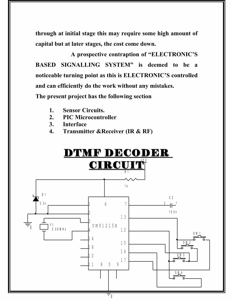
The present project has the following section
1. Sensor Circuits.2. PIC Microcontroller3. Interface 4. Transmitter &Receiver (IR & RF)
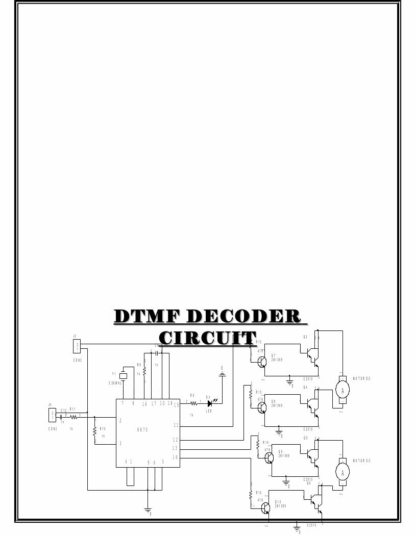
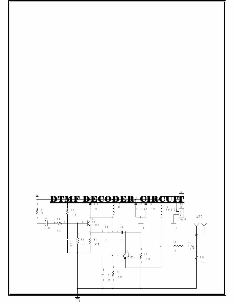
DTMF DECODERDTMF DECODER CIRCUITCIRCUIT
0
0
+ 5 V
Y 13 . 5 8 M H z
D 1
3 . 3 v
R 1
1 k
S W 2
S W 4
C 2
1 0 0 n
12
S W 1
S W 3
8 5 91 7
1 6
1 5
1 2
1 3
71
2
3
4
1 4
1 8
1 0
1 1
U M 9 1 2 1 5 B
6
DTMF DECODERDTMF DECODER CIRCUITCIRCUIT
0
0
0
0
0
0R 8
1 k
2
1
R 9
1 k
2 1
R 1 0
1 k2
1
R 1 1
1 k
21
C 9
1 n
12
C 1 2
1 n
1 2
Y 1
3 . 5 8 M H z
J 3
C O N 2
12
J 4
C O N 2
12
Q 3
C 2 5 1 0
42
3
1
Q 4
C 2 5 1 0
42
3
1
Q 5
C 2 5 1 0
42
3
1
Q 6
C 2 5 1 0
42
3
1
Q 72 N 1 0 6 91
23
Q 82 N 1 0 6 91
23
Q 92 N 1 0 6 91
23
Q 1 02 N 1 0 6 91
23
A-
+ M O T O R D C
12
A-
+ M O T O R D C
12
R 1 2
4 7 K
2
1
R 1 3
4 7 K
2
1
R 1 4
4 7 K
2
1
R 1 5
4 7 K
2
1
D 3
L E D
7 8 1 6 1 7 1 0 1 8 1 5
1 1
1 21 3
1 456914
3
2
8 8 7 0
DTMF DECODER CIRCUITDTMF DECODER CIRCUIT
0
0
+ 8 v
0
Q 14 9 4
32
1
Q 2C 2 5 7 0
32
1
R 14 7 k
2
1
R 2
1 5 k
2
1R 3
4 . 7 k
2 1
R 4
4 . 7 k
2
1
R 5
4 7 E
2
1
R 7
2 . 2 K
2
1
C 41 n1
2
C 1
. 0 1 u1
2
C 2
. 0 0 1 u1
2
C 7
1 n1
2
C 3
2 . 2 u F
C 1 0
1 n1
2
C 1 1
1 n1 2
L 14 T L 2
I N D U C T O R
L 3
5 T
C 1 1
1 n1
2
R 6
2 . 2 E
2
1
C 8
1 n
12
C 8
1 n
12
J 1
S W
12
J 2
s u p p ly
12 A N T

FM TRANSMITTER


APPLICATION /APPLICATION / ADVANTAGESADVANTAGES
1. PIC Microcontrollers based gate Automatic opening and closing is very useful to Indian Railway and Industries.
2. Track Sensing circuit is useful to Indian railway and coal industries.
3. Collision in is very much useful to avoid Accident in Railway.
4. All the features can be used in Railway Industries and Transport.
5. Reduces human error.
6. Man power required are reduces
7. Easy to install and construct.
8. More efficiency.
9. Useful by the people working in mines for monitoring cracks.
DETECTION OF BREAK IN TRACK
The track is supplied with a +12 v. The four ends
of the track are connected with the relay coils.In yhe
normal condition the green LED connected with the
normally open contact and the green Led is glowing
which indicates that the track has no breaks in
between.
When the track breaks in between the relay get energized and the contact now shifts to normally closed to which the red LED is connected,which will glow at once indicating that the track has break in between.The station master in turn informs the driver through the signallig system or informs the previous station to inform the driver or to

made the signals RED so that the train will stop by seeing the signals

1. ACKNOWLEDGEMENT2. INTRODUCTION.3. BLOCK DIAGRAMS & CIRCUIT DIAGRAMS.4. WORKING.5. INTRODUCTION TO PIC 16F846. STEPPER MOTOR DETAILS.7. SOFTWARE DESCRIPTION.8. DATA SHEETS.9. APPLICATIONS/ADVANTAGES.10. SYNOPSIS.11. BIBLIOGRAPHY.12. THANKS.

START & STOP OF TRAIN THROUGH REMOTE
The RF transmitter is placed at the signal room for transmitting signals in the range of RF and the RECEIVER is placed in the train engine to receive the signals. The power supply to the train engine motor is controlled by the RF receiver in the train engine. In the normal condition the RF transmitter in the signal room is not transmitting the signals and the train is running without any hurdles.
When the train arrives near the station the signalmen in the signal room will start transmitting signals which will be received by the receiver in the train engine, which in turn stops the power supply to the train engine motor, resulting in the stoppage of train at the station. This feature can also be used to stop the train in the case of emergency like breakage of track or some accidents.

INFRARED TRANSMITTER & RECEIVER

20 Sec. VOICE20 Sec. VOICE RECORDING
Features: Single ship, high qualities voice recording and playback solution.1) No external IC’s required2) Minimum external components Non volatile flash memory
technology3) NO Battery back up required4) 100K year message retention (typical)5) 100year message retention(typical)6) Single message of 20 to 30 seconds, with external resistor selection.7) User friendly easy to use operation 8) Programming and development systems not required 9) Level activated recording and edge-activated playback switches10) Low power consumption.11) Operating current : 25 mA (typically, no load)12) Standby current: 1uA (typically, no load) Automatically power
down features for longer battery life chip enable pin for simple message expansion single 5v power supply.
GENERAL DESCRIPTION:The APR 9301 devices offer true single chip solid state storage capability and requires no software or micro controller support. It provides high quality recording and playback with a single 20 to 30 second message it is deal for portable voice recorders, toys and many other other consumer and industrial applications.
Invox proprietary analog/multi-level storage technology is implemented in advanced flash non-volatile memory cells, each of which can typically store more than 256 voltage levels. The APR 9301

device stores and reproduces voice signals in their natural forms, eliminating the distortion that is often introduced by encoding a compression. The device combines a small size with low power consumption, non- volatility, and ease of use for a cost effective solution to voice recording and playback.
ANNNOUNCEMENT AT THEANNNOUNCEMENT AT THE RAILWAY STATIONRAILWAY STATION
SAMPLE APPLICATION:
Figure 3 shows the diagram for a single, 20 second message recording and Figure 3 shows the diagram for a single, 20 second message recording and playback applications using the APR 9301 device. When pins are connected as playback applications using the APR 9301 device. When pins are connected as shown in this example, the operation modes are as follows:shown in this example, the operation modes are as follows:
Record Mode (Level Activated ):
The / LED pin will go low during the actual recording process to provide a visual indication if an led light is connected to this pin. A single voice message of up to mode as long as the / Recl pins stays low (level activated). If the message lasts longer than 20 seconds recording will terminate automatically after do last available memory cell is written. If the message is shorter than 20 seconds are the recording operation will stop when the Recl pin goes high. The speaker driver is automatically tristated during the recording operation.
Message up to 30 seconds can be recorded by using different Osc R resistor values (see table 1 )
Playback Mode (Edge – Activated):
Playback always starts from the beginning of the message. The chip is in playback mode after the/Play E Pin sage. The chip is in playback mode after the/playback will stop immediately when the play E pin pulses low a second time if the newly recorded message is shorter the previously recorded message will be played after te message s played back. The input pre amplifier. A G C and main amp. The input pre-amplifier . AGC, and main app. Circuits are disabled during play back.

Stand by Mode:(/CE = “0”)The chip will automatically return to the stand by standby state after
recording or playback operation is completed.
Power Down Mode (/CE = “1”)The chip is always in stand by state. No recording or playback Is allowed.
Current consumption is typically less than 1uA
PIN DIAGRAM OF 9301:-
1
2
3
4
5
6
7
8
9
1 0
1 1
1 2
1 3
1 4
2 8
2 3
1 7
2 4
1 8
2 0
2 5
1 6
1 9
2 2
2 7
2 1
1 5
2 6
N C
N C
N C
N C
N C
N C
N C
N C
/ C E
O s c r
N U 1
V s s D
S P +
S P -
V c c D
/ R e c L
N U 2
L E D
N C
/ P L A Y E
N C
A n a O u t
A n a i n
A G C
M i c R e f
M i c i n
V c c A
V s s A
A P R 9 3 0 1 - V 2

CIRCUIT DIAGRAM FOR CONNECTION FOR RECORDING AND PLAYING OF MESSAGE IN
9301 :-
0
0
V C C _ C I R C L E
R 1
1 k
21
R 2
1 k
21
R 3
1 k
21
R 4
1 k
21
R 5
1 k
21
R 6
2 2 0 k
21
C 1
1
2
C 20 . 1 u F
1
2
C 3
0 . 1 u F
12
C 4
0 . 1 u F
12
C 5
0 . 1 u F
1 2 C 6
4 . 7 u F
12 C 7
2 2 u F n
1
2
V 1
6 v
L S 1
S P E A K E R
L S 2
S P E A K E R
D 1
R 7
4 . 7 k
21
S W 11 2
S W 21 2
1
2
3
4
5
6
7
8
9
1 0
1 1
1 2
1 3
1 4
2 8
2 3
1 7
2 4
1 8
2 0
2 5
1 6
1 9
2 2
2 7
2 1
1 5
2 6
N C
N C
N C
N C
N C
N C
N C
N C
/ C E
O s c r
N U 1
V s s D
S P +
S P -
V c c D
/ R e c L
N U 2
L E D
N C
N C
/ P L A Y E
N C
A n a O u t
A n a i n
A G C
M i c R e f
M i c i n
V c c A
V s s A
A P R 9 3 0 1 - V 2
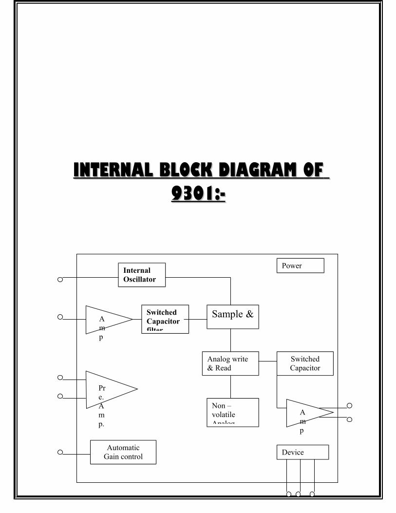
INTERNAL BLOCK DIAGRAM OFINTERNAL BLOCK DIAGRAM OF 9301:-9301:-
InternalOscillator
Device Control
AutomaticGain control
(AGC)
Non – volatile Analog
Switched Capacitor filter
Sample &
hold
Analog write & Read circuits
SwitchedCapacitor
filter
Power supply
Pre.Amp.
Amp
Amp
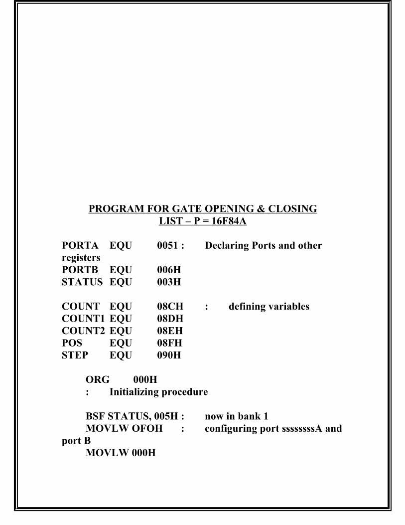
PROGRAM FOR GATE OPENING & CLOSINGLIST – P = 16F84A
PORTA EQU 0051 : Declaring Ports and other registersPORTB EQU 006HSTATUS EQU 003H
COUNT EQU 08CH : defining variablesCOUNT1 EQU 08DHCOUNT2 EQU 08EHPOS EQU 08FHSTEP EQU 090H
ORG 000H: Initializing procedure
BSF STATUS, 005H : now in bank 1MOVLW OFOH : configuring port ssssssssA and
port BMOVLW 000H

MOVWF PORT BBCF STATUS, 005H; now in bank 0
*******************PROGRAM STARTS HERE*************
CLRF PORTA ; Clearing port A & port B and initializing POS=50CLRF PORT BMOVLW 032HMOVWF POS
CALL STEPINIT; To initialize STEP = 1
START MOVF POS, 0 ; displaying the contents of POS register
CALL DISPLAYMOVWF PORT B
BTFSC PORTA, 004H;Taking input from port B & checking for zero
GOTO WEST ; East if input is zero (STEP++) & (POS++); Else go to WEST (STEP) & (POS++)
EAST INCF STEP, 1INCF POS , 1MOVF POS, 0SUBLW 064HBTFSC STATUS, 002HCALL POS 100GOTO STEP CORRECTION
WEST DECF STEP, 1DECF POS, 1
MOVF POS, 0SUBLW 000HBTFSC STATUS, 002HCALL POS000
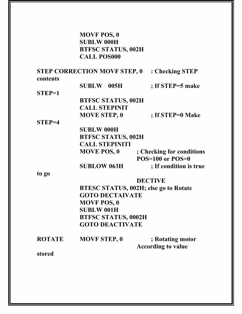
STEP CORRECTION MOVF STEP, 0 : Checking STEP contents
SUBLW 005H ; If STEP=5 make STEP=1
BTFSC STATUS, 002HCALL STEPINITMOVE STEP, 0 ; If STEP=0 Make
STEP=4SUBLW 000HBTFSC STATUS, 002HCALL STEPINITIMOVE POS, 0 ; Checking for conditions
POS=100 or POS=0SUBLOW 063H ; If condition is true
to goDECTIVE
BTESC STATUS, 002H; else go to RotateGOTO DECTAIVATEMOVF POS, 0SUBLW 001HBTFSC STATUS, 0002HGOTO DEACTIVATE
ROTATE MOVF STEP, 0 ; Rotating motorAccording to value
stored

CALL MOTOR ; in step register by calling
Look up tableMOVWF PORT ACALL DELAYGOTO START
;_______________________________________________________________________
DEACTIVATEMOVLW 0000H; deactivating all coils of stepper
MOVFW POART A; Motor Thus stopping itGOTO START
;___________________________________________________________________________
POS 000 MOVLW 001H; Initializing POS contents to 01MOVWF POSRETURN
;________________________________________________________________________POS 100 MOVLW 063H; Initializing POS contents to 99
MOVWF POSRETURN
;_________________________________________________________________________
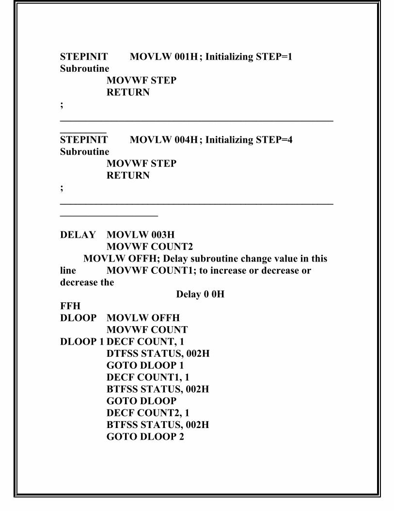
STEPINIT MOVLW 001H; Initializing STEP=1 Subroutine
MOVWF STEPRETURN
;______________________________________________________________STEPINIT MOVLW 004H; Initializing STEP=4 Subroutine
MOVWF STEPRETURN
;________________________________________________________________________
DELAY MOVLW 003HMOVWF COUNT2
MOVLW OFFH; Delay subroutine change value in this line MOVWF COUNT1; to increase or decrease or decrease the
Delay 0 0HFFHDLOOP MOVLW OFFH
MOVWF COUNTDLOOP 1 DECF COUNT, 1
DTFSS STATUS, 002HGOTO DLOOP 1DECF COUNT1, 1BTFSS STATUS, 002HGOTO DLOOPDECF COUNT2, 1BTFSS STATUS, 002HGOTO DLOOP 2

RETURN;______________________________________________________________________MOTOR ADDWF PCL, 1 ; Stepper motor lookup table
NOPRETLW 001HRETLW 001HRETLW 001HRETLW 001H
;___________________________________________________________________DISPLAYADDWF PCL, 1; seven segment display looks up table
NOP
RETLW 001H ; (09 – 10)RETLW 002HRETLW 003HRETLW 004HRETLW 005HRETLW 006HRETLW 007HRETLW 008HRETLW 009HRETLW 010H

RETLW 011H ; (11 – 20)RETLW 012HRETLW 013HRETLW 014HRETLW 015HRETLW 016HRETLW 017HRETLW 018HRETLW 019HRETLW 020H
RETLW 021H ; (21 – 30)RETLW 022HRETLW 023HRETLW 024HRETLW 025HRETLW 026HRETLW 027HRETLW 028HRETLW 029HRETLW 030H
RETLW 031H ; (31 – 40)RETLW 032HRETLW 033HRETLW 034HRETLW 035HRETLW 036HRETLW 037HRETLW 038HRETLW 039HRETLW 040H

RETLW 041H : ( 41- 50 )RETLW 042HRETLW 043HRETLW 044HRETLW 045HRETLW 046HRETLW 047HRETLW 048HRETLW 049HRETLW 050H
RETLW 051H ; ( 51 – 60 )RETLW 052HRETLW 053HRETLW 054HRETLW 055HRETLW 056HRETLW 057HRETLW 058HRETLW 059HRETLW 060H
RETLW 061H : ( 61 – 70 )RETLW 062HRETLW 063HRETLW 064HRETLW 065HRETLW 066HRETLW 067HRETLW 068HRETLW 069HRETLW 070H
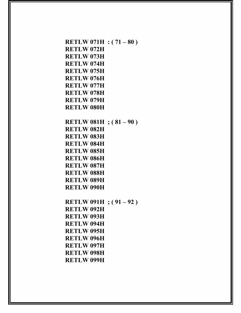
RETLW 071H : ( 71 – 80 )RETLW 072HRETLW 073HRETLW 074HRETLW 075HRETLW 076HRETLW 077HRETLW 078HRETLW 079HRETLW 080H
RETLW 081H ; ( 81 – 90 )RETLW 082HRETLW 083HRETLW 084HRETLW 085HRETLW 086HRETLW 087HRETLW 088HRETLW 089HRETLW 090H
RETLW 091H ; ( 91 – 92 )RETLW 092HRETLW 093HRETLW 094HRETLW 095HRETLW 096HRETLW 097HRETLW 098HRETLW 099H
;______________________________________________________________________
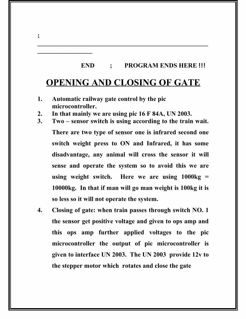
END ; PROGRAM ENDS HERE !!!
OPENING AND CLOSING OF GATE
1. Automatic railway gate control by the pic microcontroller.
2. In that mainly we are using pic 16 F 84A, UN 2003.3. Two – sensor switch is using according to the train wait.
There are two type of sensor one is infrared second one
switch weight press to ON and Infrared, it has some
disadvantage, any animal will cross the sensor it will
sense and operate the system so to avoid this we are
using weight switch. Here we are using 1000kg =
10000kg. In that if man will go man weight is 100kg it is
so less so it will not operate the system.
4. Closing of gate: when train passes through switch NO. 1
the sensor get positive voltage and given to ops amp and
this ops amp further applied voltages to the pic
microcontroller the output of pic microcontroller is
given to interface UN 2003. The UN 2003 provide 12v to
the stepper motor which rotates and close the gate
5. Opening of gate: When switch No 2 is pressed by the
train the sensor get positive voltage and given to ops amp
the ops amp further applied to pic microcontroller. The
interface IC 2003 get pulses and provide positive voltage
to the motor which rotate anti clock wise results in
opening of the railway gate.
IR RECEIVERIn receiver there are 5 transistor used. Transistor 1-4 is used
as amplifier and transistor 5 is used for gate (open and
closing) and providing negative voltage to the relay through
emitter to collector.
WORKINGThe receiver IR LED is placed in the base of transistor Q1.
The received IR signals is amplified at transistor Q1 and out
put is taken from collector and given to the base of transistor
Q2. The transistor Q2 is amplified input signal and fed to the
base of transistor Q3 through coupling capacitor Q4 and out
put is taken from collector and fed to the base transistor Q4
through resister R8 and R9 and it is worked as a coupling, the
out put from collector is given transistor Q5 through the diode
D1.
The diode D1 is providing positive half cycle to the
transistors. The diode D2 used as a polarity diode. The
negative voltage is extended from emitter to collector to the
relay. When there is no input signals the transistor 1-4 are
not conducting . Transistor Q5 will not operate so negative
voltage extended to the relay. One end of the relay coil is
directly connected to the positive terminal and other end is
connected to the collector of transistor Q5 which is providing
negative voltage to the relay for activation.
When
the IR sensor receive the input signal from the transmitter is
amplified by the transistor Q1 to Q4 is amplified then fed to
the base of transistor Q5 through a diode which is operating
the transistor Q5 so there is no negative voltage from collector
,the relay gets no negative volt and it is in ideal condition.
Through
relay positive voltage is extended to the buzzer and negative is
applied directly to the buzzer when the relay is in ideal
condition the buzzer is providing sound
IR TRANSMITTER
• IC 555 is used to generate a frequency in the range of IR
Frequency (level) and is fed to the base of transistor BD
140.. The transistor BD140 is amplified the IR
frequency After amplification the Transistor is drive the
IR LED for radiating the signals
• Registers are used to provide DC biasing to the IC and
transistor.
• Capacitor C1 and C2 are used for generating a
frequency in the range of IR level (infrared range).

INTRODUCTION TOMICROCONTROLLER
Circumstances that we find ourselves in today in the
field of microcontrollers had their beginning in the
development of technology of integrated circuits. This
development has made it possible to store hundreds of
thousands of transistors in to one chip. That was a
prerequisite for production of microprocessors, and the first
computers were made by adding external peripherals such as
memory, input lines, timers and other. Further Increasing of
the volume of the package resulted in creation of integrated
circuits. These integrated circuits contained both processor

and peripherals. That is how the first chip containing a
microcomputer or what would later be knows as a
microcontroller came about.
PINS IN PIC16F84:
PIC16F84 has a total of 18 pins. It is most frequently found in a DIP18 type of
housing but can also be found in SMD housing which is smaller from a DIP.
DIP is short for dual in package. SMD is short for surface mount devices
suggesting that holes for pins to go through when mounting aren’t necessary in
soldering this type of a component.
Pins on PIC16F84 micro controller have the following meaning: Pin no.1 RA2 Second pin on port A.had no additional function.Pin no.2 RA3 Third pin on port A. Had no additional function.Pin no.3 RA4 Fourth pin on port A. Tock1 which functions as a timer is also found on this pin.Pin no.4 MCLR reset input and Vpp programming voltage of a micro controller.
Pin no.5 Vss supply, mass.Pin no.6 RBO first pin on port B. Interrupt input is an additional Function.Pin no.7 RB1 First pin on B. no additional function.Pin no.8 RB2 Second pin on port B. no additional function.Pin no.9 RB3 Third pin on port B. no additional function.Pin no.10 RB4 Fourth pin on port B. no additional function.Pin no.11 RB5 Fifth pin on port B. no additional function. Pin no.12 RB6 Sixth pin on port B. “Clock” line in program mode.Pin no.13 RB7 Seventh pin on port B. Given line in program mode.Pin no.14 RBO Vdd positive supply pole.Pin no.15 OSC2 pin assigned for connecting with an oscillatorPin no.16 OSC1 pin assigned for connecting with an oscillator.Pin no.17 RA2 Second pin on port A. No addition function.Pin no.18 RA1 First pin on port A. No additional function.
More about Micro controller PIC16F84 PIC16F84 belongs to class of 8 big Micro controllers of PIS
architecture. Its general structure is shown on the following
map representing basic blocks.
Memory organization PIC16F84 has two separate memory blocks, one for data and
the other for program. EEPROM memory and GPR
registers in RAM memory make up a block for data,
and FLASH memory make up a program block.

PROGRAM MEMORYProgram memory has been realized in FLASH technology
which makes it possible to program a micro controller many
times before it’s installed into a device and even after its
installment if eventual changes in program or process
parameters should occur. The size of program memory is
1024 location with 14 bits width were location zero and four
are reserved for reset and interrupt vector
DATA MEMORY Data memory consists of EEPROM and RAM memories.
EEPROM memory consists of 64 eight bit locations whose
contents are not lost during an interrupt in supply. EEPROM
is not stored directly in memory space, but is accessed
indirectly through EEADR and EEDATA registers.
Data
Memory RAM
Free Counter
Data Memory EEOROM
Program Memory FLASH
PORTA PORT B
CPU
IR RECEIVERIn receiver there are 5 transistor used. Transistor 1-4 is used as
amplifier and transistor 5 is used for gate (open and closing) and
providing negative voltage to the relay through emitter to collector.
The
receiver IR LED is placed in the base of transistor Q1. The received
IR signals is amplified at transistor Q1 and out put is taken from
collector and given to the base of transistor Q2. The transistor Q2 is
amplified input signal and fed to the base of transistor Q3 through
coupling capacitor Q4 and out put is taken from collector and fed to
the base transistor Q4 through resister
R8 and R9 and it is worked as a
coupling, the out put from collector is given transistor Q5 through the
diode D1.
The diode D1 is providing positive half cycle to the
transistors. The diode D2 used as a polarity diode. The negative
voltage is extended from emitter to collector to the relay. When there
is no input signals the transistor 1-4 are not conducting . Transistor Q5
will not operate so negative voltage extended to the relay. One end of
the relay coil is directly connected to the positive terminal and other
end is connected to the collector of transistor Q5 which is providing
negative voltage to the relay for activation.
When the IR sensor receive the input signal from the transmitter is
amplified by the transistor Q1 to Q4 is amplified then fed to the base of
transistor Q5 through a diode which is operating the transistor Q5 so
there is no negative voltage from collector ,the relay gets no negative
volt and it is in ideal condition.
Through relay positive voltage is
extended to the buzzer and negative is applied directly to the
buzzer when the relay is in ideal condition the buzzer is
providing sound
USES AND APPLICATIONS
1 It is used in Lift system (Apartment)2 It can also use in defence ( arms ammunition)3 It is used in Metro train4 Easy to maintain5 Performance of this circuit is good6 It is used in Air port for auto opening gate
WIRELESS SIGNALLING IN RAILWAYSWIRELESS SIGNALLING IN RAILWAYS
The word “Wireless” means sending the signals without using The word “Wireless” means sending the signals without using any wires. The whole purpose of the “Wireless” is to any wires. The whole purpose of the “Wireless” is to eliminate the any kind of cabling between the source and eliminate the any kind of cabling between the source and destinations. Not only that, also to get the work done in more destinations. Not only that, also to get the work done in more reliable way with fast speed. In simple way, if the process reliable way with fast speed. In simple way, if the process takes place using the Radio Frequency and Infra Red Rays, takes place using the Radio Frequency and Infra Red Rays, without using any type of cabling is called as Wireless without using any type of cabling is called as Wireless Communication. For example, if the protection of any vehicleCommunication. For example, if the protection of any vehicle
is accomplished using less work supervision and more self-is accomplished using less work supervision and more self-caring and self-decisive devices. It may be referred as ‘that caring and self-decisive devices. It may be referred as ‘that vehicle is automated’. With the golden rule’ prevention is vehicle is automated’. With the golden rule’ prevention is better than cure’, vehicle can be well protected from any better than cure’, vehicle can be well protected from any major accident or disaster or damage by automating it. In major accident or disaster or damage by automating it. In brief,’Vegicle Automation’ means protecting or doing every-brief,’Vegicle Automation’ means protecting or doing every-day running processes using any electronic or computer day running processes using any electronic or computer guided Instrument.guided Instrument.
Stop-Go type Signalling system is too much essential for Stop-Go type Signalling system is too much essential for Railway Communication. In the early days, manually Railway Communication. In the early days, manually controlled mechanical Up-Down signals were in use for controlled mechanical Up-Down signals were in use for indicating Stop-Go through any particular Railway track. indicating Stop-Go through any particular Railway track. But, at present, electronic signaling systems are being But, at present, electronic signaling systems are being extensively used for this purpose. In our country, manually extensively used for this purpose. In our country, manually operated electrical signaling systems are still in wide use operated electrical signaling systems are still in wide use because of several unavoidable factors, such as, because of several unavoidable factors, such as, Unemployment Problems, Economical Condition of the Unemployment Problems, Economical Condition of the Country etc. It’s a common experience of all of us that, for Country etc. It’s a common experience of all of us that, for such manual operation of the signaling systems, several such manual operation of the signaling systems, several disturbances in train service very often occur due to the disturbances in train service very often occur due to the negligence in duties and also due to some personal errors of negligence in duties and also due to some personal errors of the signalers. Even, fatal accidents might happen sometimes the signalers. Even, fatal accidents might happen sometimes in a busy Railway-track due to some minor mistakes of a in a busy Railway-track due to some minor mistakes of a signaler in his signaler in his signaling techniques. Such signaler in his signaler in his signaling techniques. Such factors may be avoided in a great extent only if the signaling factors may be avoided in a great extent only if the signaling systems are made in entirely automatic manner.systems are made in entirely automatic manner.
Our present Model is a minor attempt to find out how the Our present Model is a minor attempt to find out how the aforesaid idea can be implemented. Though this model will aforesaid idea can be implemented. Though this model will not serve the purpose of actual commercial use, yet it is not serve the purpose of actual commercial use, yet it is

sufficient to show the way through which we can proceed to sufficient to show the way through which we can proceed to make the Train Signalling Systems completely automatic with make the Train Signalling Systems completely automatic with the aid of Electronics.the aid of Electronics.
Specific about the Project: Railway are the lifelines of a Specific about the Project: Railway are the lifelines of a country. Train mishaps have been occurring since their country. Train mishaps have been occurring since their inception, yet we are unable to prevent accidents and inception, yet we are unable to prevent accidents and safeguard valuable life and properly. Some of the reasons safeguard valuable life and properly. Some of the reasons associated with train mishaps are: Some obstructions in front associated with train mishaps are: Some obstructions in front of the signal; Signal bulb burnout; Driver’ carelessness in not of the signal; Signal bulb burnout; Driver’ carelessness in not sighting the signal due to fatigue; Due to denses fog and brightsighting the signal due to fatigue; Due to denses fog and bright sunlight the signal light may not visible to driver properly etc.sunlight the signal light may not visible to driver properly etc.
From above reasons we can see that the main problem is From above reasons we can see that the main problem is traditional bulb signaling system that we are using. So if we traditional bulb signaling system that we are using. So if we can replace this with a stand by system using the modern can replace this with a stand by system using the modern methods of ELECTRONICS AND COMMUNICATION. Themethods of ELECTRONICS AND COMMUNICATION. The system going to be described is a totally new one, which may system going to be described is a totally new one, which may add cost, but in long run if can successfully replace the bulb add cost, but in long run if can successfully replace the bulb signaling system and total electronic control of train is signaling system and total electronic control of train is possible. possible.
STEPPER MOTOR EXPLANATION

In this project we are using the stepper motor as
per the specification mentioned above. The stepper
motor is a 4 pole where in this poles are connected to
the relay and is controlled by the relay driver IC ULN
2003. At any given instant of time only 1 relay is
activated such that depending upon the particular
relay activated that particular pole in stepper motor is
energized and accordingly the stepper motor moves to
that particular pole due to excitation. Depending on
the type of relay to be activated and the particular
order. Stepper motor accordingly moves in either
clock wise or anti - clockwise direction.
Stepper Motor Specification:
1. Step Angle 0.5%
2. Step angle accuracy 5%
3. Rate phase current 0.22A
4. Phase resistance 23 ohms
5. Phase inductance 300 m H
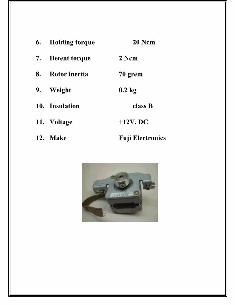
6. Holding torque 20 Ncm
7. Detent torque 2 Ncm
8. Rotor inertia 70 grem
9. Weight 0.2 kg
10. Insulation class B
11. Voltage +12V, DC
12. Make Fuji Electronics

FEATURE

SCONTEN

TSSYNOPS

IS
DATA
SH

EETS
WORKI

NG

THANKS
BBIIBB

LLIIOOGGRRAAPPHHYY

SYNOPSSYNOPSISIS


SOFTWARESOFTWARE

DESCRIPTIONDESCRIPTION


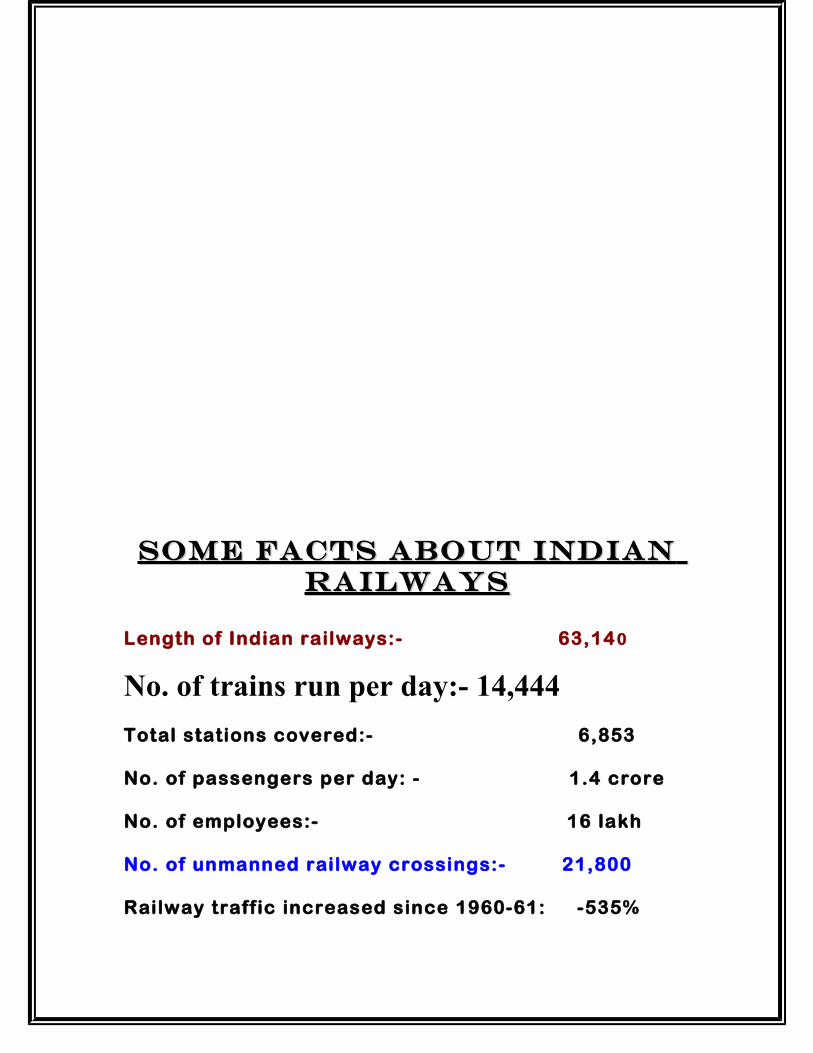
SOME FACTS ABOUT INDIANSOME FACTS ABOUT INDIAN RAILWAYSRAILWAYS
Length of Indian railways:- 63,14 0
No. of trains run per day:- 14,444
Total stations covered:- 6,853
No. of passengers per day: - 1.4 crore
No. of employees:- 16 lakh
No. of unmanned railway crossings:- 21,800
Railway traffic increased since 1960-61: -535%
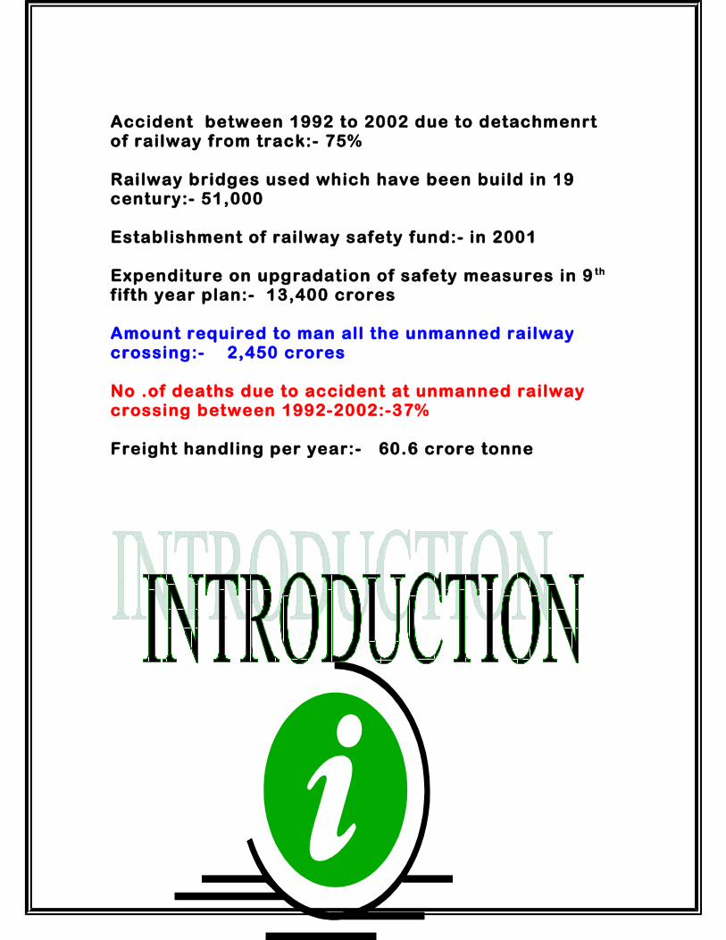
Accident between 1992 to 2002 due to detachmenrt of railway from track:- 75%
Railway bridges used which have been build in 19 century:- 51,000
Establishment of railway safety fund:- in 2001
Expenditure on upgradation of safety measures in 9 th f ifth year plan:- 13,400 crores
Amount required to man all the unmanned railway crossing:- 2,450 crores
No .of deaths due to accident at unmanned railway crossing between 1992-2002:-37%
Freight handling per year:- 60.6 crore tonne

SYNOPSISSYNOPSISThe project presented here is novel approach to the signaling & safety system
of the Railway System. The modern electronic system is basically useful to
warn/display the status of the traffic signals to the driver. Here, the traffic
signals are direct in the hands of the signalmen and he can take appropriate
action.
In conventional method, the Railway Signalmen operate the particular
electromechanical switches to illuminate the desired incandescent bulbs located at a

pole near the railway station. The railway driver is supposed note the status of the
signals & depending upon the same he is supposed to mover further or stop the train.
If due to the mist/fog or smoke or any other reason, suppose the driver is not able the
notice or see the signal lights, he may not be able to judge the situation and may lead
to possible accident and loss of life and property.
Here, in contrast to this existing system, we are trying to provide a solution to this
system by designing a device which displays the signals to the station master that
includes the status of the track, announcement at railway station and the status of
the track(free or not)is displayed or the engine driver can hear and take preventive
measure.

1. Features of the project.1. Features of the project.2. Introduction.2. Introduction.3. Working.3. Working.4. Block Diagrams.4. Block Diagrams.

5. Software Description.5. Software Description.6. Introduction to PIC microcontroller.6. Introduction to PIC microcontroller.7. Details of Stepper motor.7. Details of Stepper motor.8. Details of APR 9301-V2(announcement ic).8. Details of APR 9301-V2(announcement ic).9. Synopsis.9. Synopsis.10.Data Sheets.10.Data Sheets.11.Application/Advantages.11.Application/Advantages.12.Bibliography.12.Bibliography.