RAILBLAZERS® Aluminum Railing System · No representation or warranty is given that your...
25
No representation or warranty is given that your particular application of these products complies with relevant building codes or that the fasteners provided or used are appropriate for your application. Therefore consult with professionals and local building officials before beginning work: (i) to ensure compliance with relevant building codes for your application and for your proposed use of fasteners; (ii) to ensure the integrity of the structural components in connection with which these products are to be used; (iii) to identify appropriate safety gear that is to be used during installation such as a safety harness when working above ground; (iv) to ensure that the work area is free from utilities, services and hazards; and, (v) to clarify any instructions or warnings that may not be clear. Work in a safe manner wearing protective gear such as gloves, eyewear, headwear, footwear and clothing. When using tools always comply with operation manuals and instructions. Metal and glass may have sharp edges and could fragment or splinter during or as a result of handling or cutting. Do not use these products in connection with any substance that is or may be harmful or corrosive to the products. Inspect and maintain these products and the structural components that they are used in connection with on a regular basis using professionals when appropriate. These instructions have been prepared for certain standard residential applications. Obtain professional advice for any non-standard or non-residential application. WARNING • • • •
Transcript of RAILBLAZERS® Aluminum Railing System · No representation or warranty is given that your...

No representation or warranty is given that your particular application of these products complies with relevant building codes or that the fasteners provided or used are appropriate for your application.
Therefore consult with professionals and local building officials before beginning work: (i) to ensure compliance with relevant building codes for your application and for your proposed use of fasteners; (ii) to ensure the integrity of the structural components in connection with which these products are to be used; (iii) to identify appropriate safety gear that is to be used during installation such as a safety harness when working above ground; (iv) to ensure that the work area is free from utilities, services and hazards; and, (v) to clarify any instructions or warnings that may not be clear. Work in a safe manner wearing protective gear such as gloves, eyewear, headwear, footwear and clothing. When using tools always comply with operation manuals and instructions. Metal and glass may have sharp edges and could fragment or splinter during or as a result of handling or cutting. Do not use these products in connection with any substance that is or may be harmful or corrosive to the products. Inspect and maintain these products and the structural components that they are used in connection with on a regular basis using professionals when appropriate. These instructions have been prepared for certain standard residential applications. Obtain professional advice for any non-standard or non-residential application.
WARNING
••••

RAILBLAZERS® Aluminum Railing System &
RAILBLAZERS® Continuous Handrail
Engineering Review for Compliance with
Canadian Building Codes Part 9
Peak Products Manufacturing Inc.
December 14, 2016
RJC No. VAN.106169.0014
Prepared for:
Peak Products Manufacturing Inc.
www.peakproducts.com
Prepared by:
Read Jones Christoffersen Ltd.
1285 West Broadway, Suite 300
Vancouver BC V6H 3X8

RAILBLAZERS® Aluminum Railing System & RAILBLAZERS® Continuous Handrail
Engineering Review for Compliance with Canadian Building Codes Part 9
December 14, 2016 RJC No. VAN.106169.0014
Table of Contents
1 . 0 O V E R V I E W 1
2 . 0 I N F I L L E L E M E N T S 2
2 . 1 A l u m i n u m I n f i l l E l e m e n t s 2
2 . 2 G l a s s I n f i l l E l e m e n t s 2
3 . 0 R A I L E L E M E N T S 3
3 . 1 G e n e r a l R a i l E l e m e n t s 3
3 . 2 C o n t i n u o u s R a i l E l e m e n t s 3
4 . 0 C O N N E C T O R S 4
4 . 1 C o n n e c t o r s 4
5 . 0 R E S U L T S 4
6 . 0 C O N C L U S I O N 4
APPENDIX A: LIST OF COMPONENTS
APPENDIX B: ASSEMBLY DRAWINGS
RAILBLAZERS® Aluminum Railing System & RAILBLAZERS® Continuous Handrail
Engineering Review for Compliance with Canadian Building Codes Part 9
December 14, 2016 RJC No. VAN.106169.0014 page 1
1 . 0 O VE RVIE W
The RailBlazers® Aluminum Railing System is intended to act as a guard or barrier to protect the public
from a fall and the RailBlazers® Continuous Handrail is intended to act as a guide and support on
walking surfaces. The objectives were to complete a structural review of the structural components
based on Limit States Design, in accordance with applicable material standards and Part 9 of the
following Canadian building codes:
Alberta Building Code 2014
British Columbia Building Code 2012
National Building Code of Canada 2015
Ontario Building Code 2012
For the RailBlazers® Aluminum Railing System, the following specified loads apply (1 and 2 dwelling
units):
Concentrated lateral load of 1 kN (applied the Railing System at top of guard)
Uniformly distributed lateral load of 0.50 kN/m (applied at top of guard)
Uniformly distributed vertical load of 1.5 kN/m (applied at top of guard)
Concentrated infill load of 0.5kN (anywhere within the guard)
For the RailBlazers® Continuous Handrail, the following specified loads apply (single dwelling units):
Concentrated load of 0.9 kN (applied in any direction along the handrail)
A. Infill Elements
1. Aluminum pickets 16 mm (⅝”) wide
2. Wide aluminum pickets 38 mm (1½”) wide
3. Glass panels up to 1.676 m (66”) wide
4. Glass panels 152 mm (6”) wide
B. Rail Elements
1. Post
2. Railing Handrail
3. Railing Base rail
4. Continuous Handrail
5. Continuous Handrail Splice

RAILBLAZERS® Aluminum Railing System & RAILBLAZERS® Continuous Handrail
Engineering Review for Compliance with Canadian Building Codes Part 9
December 14, 2016 RJC No. VAN.106169.0014 page 2
C. Connectors
1. Universal connector
2. Wall mount brackets
3. Mid/stair/end fascia mount bracket
4. Corner fascia mount bracket
5. Continuous handrail bracket
6. Continuous Handrail Post Connection
7. Wood stud/blocking connection
The complete list of all components (including non-structural components) for the system is included
in Appendix A.
2 . 0 INF IL L E L E ME NT S
The primary infill elements included: 16 mm (⅝”) aluminum picket, 38 mm (1½”) wide aluminum picket,
6 mm (¼") thick glass panels (up to 1.676 m (66”) wide), and 8 mm (5/16”) thick glass panels (152 mm
(6”) wide).
The review was based on information and drawings provided by Peak Products Manufacturing Inc.
(Peak) for the elements listed above.
2 . 1 A lu m in u m In f i l l E lem e n ts
Our analysis was based on the following information:
Loads: Prescribed by the Canadian building codes. See Section 1.0, Overview.
Resistance: Completed in accordance with CAN/CSA S157-05 (R2015), Strength in Aluminum
Design.
Section properties: Determined from drawings provided by Peak. Calculations were completed in
accordance with CAN/CSA S157-05 (R2015).
Load configuration: Span and bearing lengths were provided by Peak.
2 . 2 G la s s In f i l l E lem en ts
Our analysis was based on the following information:
Loads: Prescribed by the Canadian building codes. See Section 1.0, Overview.
Resistance: Completed in accordance with CAN/CGSB 12.20-M89, Structural Design of Glass for
Buildings.
Material: Tempered glass in accordance with CAN/CGSB-12.1-M90 per information and drawings
provided by Peak.
Section properties: Determined from drawings provided by Peak.

RAILBLAZERS® Aluminum Railing System & RAILBLAZERS® Continuous Handrail
Engineering Review for Compliance with Canadian Building Codes Part 9
December 14, 2016 RJC No. VAN.106169.0014 page 3
Load configuration: Span and bearing lengths were provided by Peak. The glass panels were
analyzed based on having pinned (simply-supported) ends at the top and bottom.
Allowable deflection: The allowable deflection was calculated based on preventing fall-out of the
glass from the frame.
3 . 0 RA IL E L E ME NT S
3 . 1 G en er a l Ra i l E lem en ts
The general rail elements include the hand rail, base rail, and posts. An analysis was completed based
on the worst-case configuration for these elements.
Loads: Prescribed by the Canadian building codes. See Section 1.0, Overview.
Resistance: Completed in accordance with CAN/CSA S157-05 (R2015), Strength in Aluminum
Design.
Section properties: Determined from drawings provided by Peak. Calculations were completed in
accordance with CAN/CSA S157-05 (R2015).
Fastener resistance: Completed in accordance with CAN/CSA S16-14, Design of Steel Structures.
Load configuration: Span and dimensions were provided by Peak. Posts were modeled as
cantilevers, fixed at the base. The results from our analysis show the maximum span that can be
achieved, as calculated from the material and fastener resistances.
3 . 2 C o n t in u o u s Ra i l E lem e n ts
The primary rail elements include the handrail and splice (which is used to join lengths of handrail
together).
Our analysis was based on the following information:
Loads: Prescribed by the Canadian building codes. See Section 1.0, Overview.
Resistance: Completed in accordance with CAN/CSA S157-05 (R2015), Strength in Aluminum
Design.
Section properties: Determined from drawings provided by Peak. Calculations were completed in
accordance with CAN/CSA S157-05 (R2015).
Load configuration: Span and bearing lengths were provided by Peak.

RAILBLAZERS® Aluminum Railing System & RAILBLAZERS® Continuous Handrail
Engineering Review for Compliance with Canadian Building Codes Part 9
December 14, 2016 RJC No. VAN.106169.0014 page 4
4 . 0 C O NNE C T O RS
4 . 1 C o n n ecto r s
The general connectors included the universal connector, wall mount brackets, mid/stair/end fascia
mount bracket, corner fascia mount bracket, Continuous bracket, Continuous-Railing System post
connection, and wood stud/blocking connection. An analysis was completed based on the worst-case
configuration for these elements.
Loads: Prescribed by the Canadian building codes. See Section 1.0, Overview.
Resistance: Completed in accordance with CAN/CSA S157-05 (R2015), Strength in Aluminum
Design and CAN/CSA S16-14, Design of Steel Structures.
Section properties: Determined by drawings provided by Peak. Calculations were completed in
accordance with CAN/CSA S157-05 (R2015).
Load configuration: Span and dimensions were provided by Peak.
Connections to the base building are not included as part of this review, including but not limited
to the rail and post connections.
5 . 0 RE S U L T S
A full set of calculations and results is presented in RJC #VAN.106169.0014 engineering review
package, including:
Dimensioned drawings of each component, including extrusion drawings
Calculation sheets for the structural capacity of components listed in 1.0 Overview
The above documents contain proprietary information and as such, have not been included in this
report.
6 . 0 C O NC L US IO N
The RailBlazers® Aluminum Railing System meets the requirements for 1 and 2 dwelling units within
Part 9 of the Alberta Building Code 2014, British Columbia Building Code 2012, National Building Code
of Canada 2015, and Ontario Building Code 2012.
The RailBlazers® Continuous Handrail meets the requirements for single dwelling units within Part 9
of the Alberta Building Code 2014, British Columbia Building Code 2012, National Building Code of
Canada 2015, and Ontario Building Code 2012.
Limitations of compliance are defined in the assembly drawings presented in Appendix B.

APPENDIX A
LIST OF COMPONENTS

Compliance with Canadian Building Codes Part 9 RailBlazers® Aluminum Railing System & Continuous Handrail Page 1 Appendix A - List of Components RJC No. VAN.106169.0014
Read Jones Christoffersen Ltd.
SKU (White)
SKU (Black)
Description
10000 10001 END POST
10010 10011 MID POST
10020 10021 CORNER POST
10050 10051 STAIR POST
10100 10101 4’ HAND AND BASE RAIL
10110 10111 6’ HAND AND BASE RAIL
10170 10171 CONTINUOUS HANDRAIL KIT
10200 10201 4’ STANDARD PICKETS AND SPACERS
10210 10211 6’ STANDARD PICKETS AND SPACERS
10260 10261 6’ STANDARD STAIR PICKETS AND SPACERS
10300 10301 4’ WIDE PICKETS AND SPACERS
10310 10311 6’ WIDE PICKETS AND SPACERS
10350 10351 24’ WIDE PICKETS AND SPACERS
10360 10361 6’ WIDE STAIR PICKETS AND SPACERS
10710 10713 6” GLASS PANEL & GASKET
10820 10820 GLASS PANEL 18” x 3 5/16”
10823 10823 GLASS PANEL 21” x 3 5/16”
10830 10830 GLASS PANEL 24” x 3 5/16”
10833 10833 GLASS PANEL 27” x 3 5/16”
10840 10840 GLASS PANEL 30” x 3 5/16”
10843 10843 GLASS PANEL 33” x 3 5/16”
10850 10850 GLASS PANEL 36” x 3 5/16”
10853 10853 GLASS PANEL 39” x 3 5/16”
10860 10860 GLASS PANEL 42” x 3 5/16”
10863 10863 GLASS PANEL 45” x 3 5/16”
10866 10866 HEAT SOAKED GLASS PANEL 42” x 36 5/16”
10870 10870 GLASS PANEL 48” x 3 5/16”
10873 10873 GLASS PANEL 51” x 3 5/16”
10880 10880 GLASS PANEL 54” x 3 5/16”
10883 10883 GLASS PANEL 57” x 3 5/16”
10888 10888 GLASS PANEL 60” x 3 5/16”
10891 10891 GLASS PANEL 63” x 3 5/16”
10895 10895 GLASS PANEL 66” x 3 5/16”
10900 10901 UNIVERSAL CONNECTOR
10920 10921 WALL MOUNT BRACKET
10940 10940 6’ GLASS GASKET
10960 10961 CORNER FASCIA MOUNT BRACKET
10970 10971 MID/END/STAIR FASCIA MOUNT BRACKET
10990 10991 CONTINUOUS HANDRAIL BRACKETS AND END CAPS
APPENDIX B
ASSEMBLY DRAWINGS

MAXIMUM: 1880 mm [74 in]
MAXIMUM: 100 mm [3-15/16 in]
MIN
IMUM
: 107
0 m
m [4
2-1/
8 in
]
SEE DRAWING: POSTS SEE DRAWING: BRACKETS AND CONNECTORS
3
1
4
52
ITEM NO. DESCRIPTION SKU1 STANDARD PICKET 10200, 10201, 10210, 102112 SPACER 10200, 10201, 10210, 102113 HAND RAIL 10100, 10101, 10110, 101114 BASE RAIL 10100, 10101, 10110, 101115 POST 10000, 10001, 10010, 10011, 10020, 10021
DIMENSIONS ARE IN MM UNLESS NOTED
TITLE
SIZE
BDWG. NO.
SCALE: 1:15
RailBlazers® - Railing Assembly with Pickets
Report assembly P9 Pickets
DO NOT SCALE DRAWING
Report assembly - picketsPART FILE
SHT REV2016-06-01-A
DWG REV A
THIS DRAWING AND ITS CONTENTS ARE PROPERTY OF THE ISSUING PEAK COMPANY (INCLUDING PEAK INNOVATIONS INC. AND PEAK PRODUCTS CORPORATION). ANY DISSEMINATION OR REPRODUCTION IN WHOLE OR IN PART IS STRICTLY PROHIBITED.
PROPRIETARY AND CONFIDENTIAL
Compliance with Canadian Building Codes Part 9 (1 and 2 Dwelling Units) RailBlazers® Aluminum Railing System and RailBlazers® Continuous Handrail Page 1 Appendix B - Assembly Drawings RJC No. VAN.106169.0014
MAXIMUM: 1880 mm [74 in]
MAXIMUM: 100 mm [3-15/16 in]
MIN
IMUM
: 107
0 m
m [4
2-1/
8 in
]
SEE DRAWING: POSTS SEE DRAWING: BRACKETS AND CONNECTORS
3
4
5
1
2
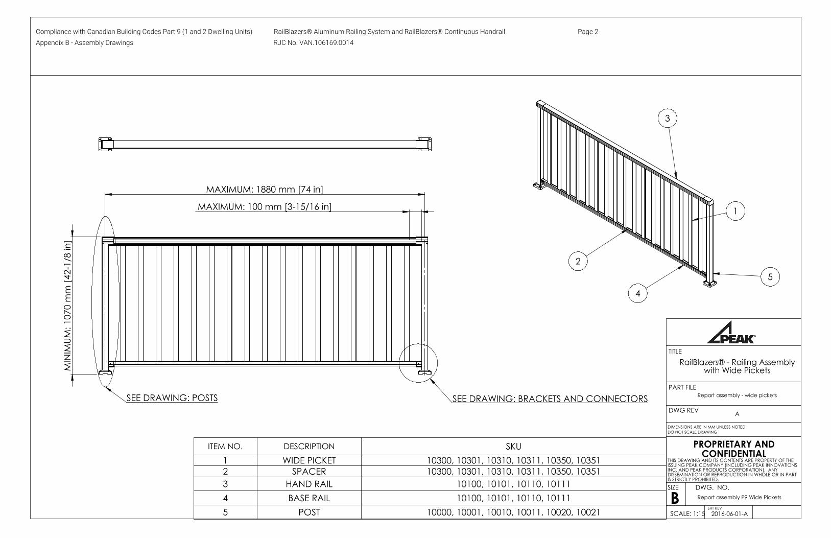
ITEM NO. DESCRIPTION SKU1 WIDE PICKET 10300, 10301, 10310, 10311, 10350, 103512 SPACER 10300, 10301, 10310, 10311, 10350, 103513 HAND RAIL 10100, 10101, 10110, 101114 BASE RAIL 10100, 10101, 10110, 101115 POST 10000, 10001, 10010, 10011, 10020, 10021
DIMENSIONS ARE IN MM UNLESS NOTED
TITLE
SIZE
BDWG. NO.
SCALE: 1:15
RailBlazers® - Railing Assembly with Wide Pickets
Report assembly P9 Wide Pickets
DO NOT SCALE DRAWING
Report assembly - wide picketsPART FILE
SHT REV2016-06-01-A
DWG REV A
THIS DRAWING AND ITS CONTENTS ARE PROPERTY OF THE ISSUING PEAK COMPANY (INCLUDING PEAK INNOVATIONS INC. AND PEAK PRODUCTS CORPORATION). ANY DISSEMINATION OR REPRODUCTION IN WHOLE OR IN PART IS STRICTLY PROHIBITED.
PROPRIETARY AND CONFIDENTIAL
Compliance with Canadian Building Codes Part 9 (1 and 2 Dwelling Units) RailBlazers® Aluminum Railing System and RailBlazers® Continuous Handrail Page 2 Appendix B - Assembly Drawings RJC No. VAN.106169.0014
MAXIMUM: 1880 mm [74 in]
MINIMUM: 457.2 mm [18 in]MAXIMUM: 1676.4 mm [66 in]
MAXIMUM: 100 mm [3-15/16 in]
107
0 m
m [4
2-1/
8 in
]
SEE DRAWING: POSTS
SEE DRAWING: BRACKETS AND CONNECTORS
6 mm (1/4") TEMPERED GLASSCAN/CGSB-12.1-M90 4
2
6
3
1
5
ITEM NO. DESCRIPTION SKU1 HAND RAIL 10100, 10101, 10110, 101112 BASE RAIL 10100, 10101, 10110, 10111
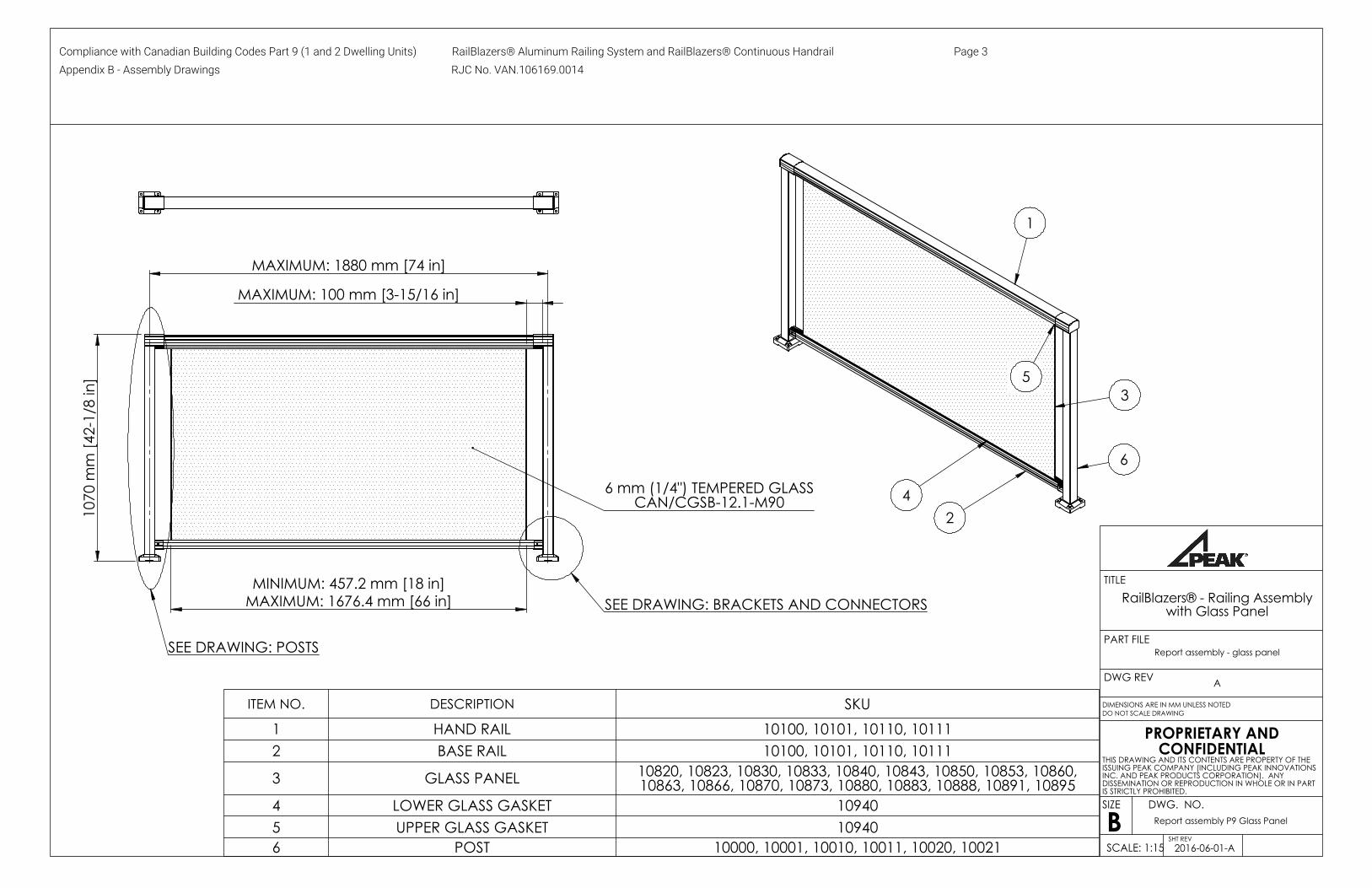
3 GLASS PANEL 10820, 10823, 10830, 10833, 10840, 10843, 10850, 10853, 10860, 10863, 10866, 10870, 10873, 10880, 10883, 10888, 10891, 10895
4 LOWER GLASS GASKET 109405 UPPER GLASS GASKET 109406 POST 10000, 10001, 10010, 10011, 10020, 10021
DIMENSIONS ARE IN MM UNLESS NOTED
TITLE
SIZE
BDWG. NO.
SCALE: 1:15
RailBlazers® - Railing Assembly with Glass Panel
Report assembly P9 Glass Panel
DO NOT SCALE DRAWING
Report assembly - glass panelPART FILE
SHT REV2016-06-01-A
DWG REV A
THIS DRAWING AND ITS CONTENTS ARE PROPERTY OF THE ISSUING PEAK COMPANY (INCLUDING PEAK INNOVATIONS INC. AND PEAK PRODUCTS CORPORATION). ANY DISSEMINATION OR REPRODUCTION IN WHOLE OR IN PART IS STRICTLY PROHIBITED.
PROPRIETARY AND CONFIDENTIAL
Compliance with Canadian Building Codes Part 9 (1 and 2 Dwelling Units) RailBlazers® Aluminum Railing System and RailBlazers® Continuous Handrail Page 3 Appendix B - Assembly Drawings RJC No. VAN.106169.0014
MAXIMUM: 1880 mm [74 in]
107
0 m
m [4
2-1/
8 in
]
MAXIMUM: 96 mm [3-25/32 in]
SEE DRAWING: BRACKETS AND CONNECTORSSEE DRAWING: POSTS
8 mm (5/16") TEMPERED GLASSCAN/CGSB-12.1-M90
1
2
5
3
4
ITEM NO. DESCRIPTION SKU
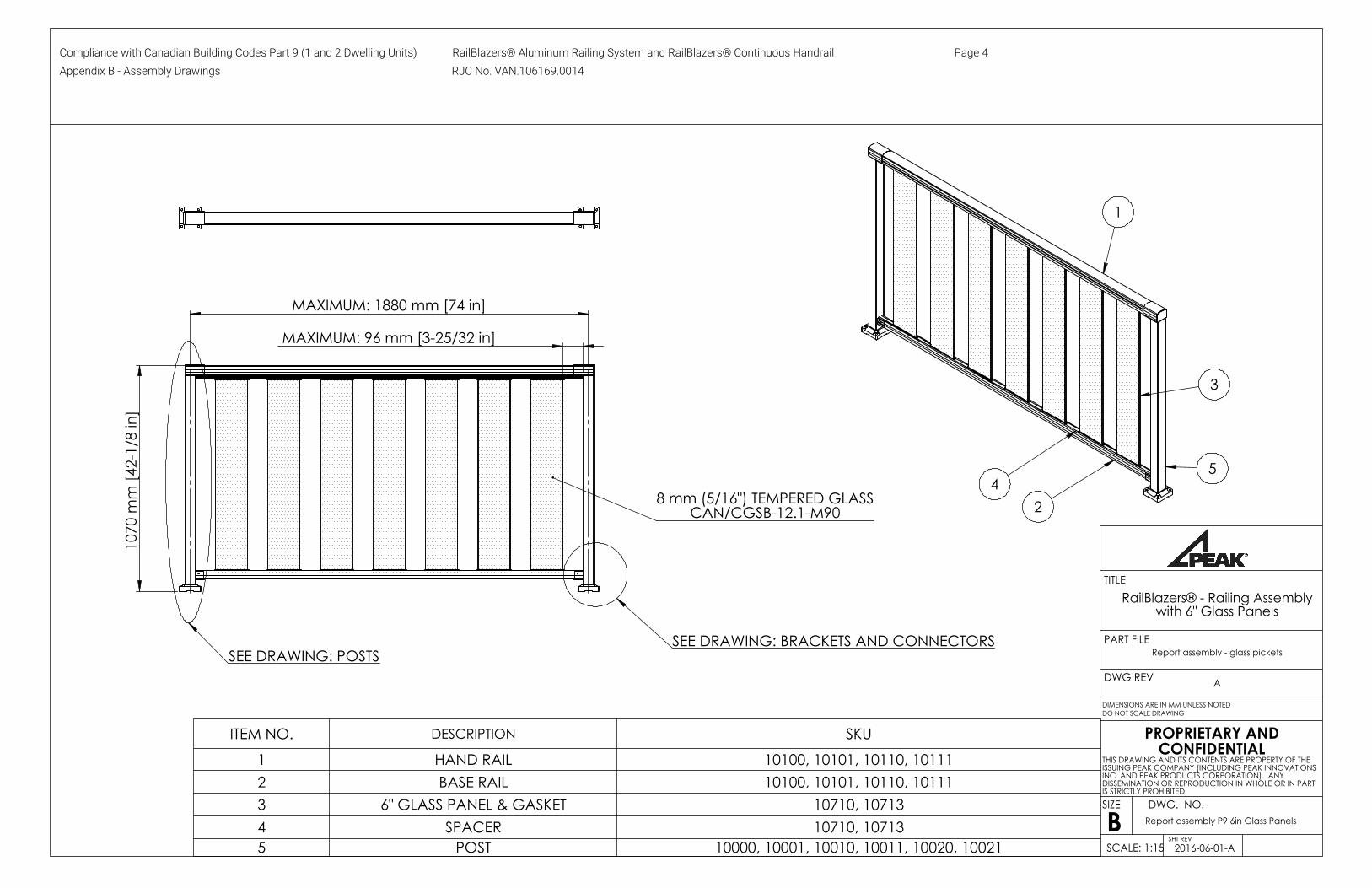
1 HAND RAIL 10100, 10101, 10110, 101112 BASE RAIL 10100, 10101, 10110, 101113 6" GLASS PANEL & GASKET 10710, 107134 SPACER 10710, 107135 POST 10000, 10001, 10010, 10011, 10020, 10021
DIMENSIONS ARE IN MM UNLESS NOTED
TITLE
SIZE
BDWG. NO.
SCALE: 1:15
RailBlazers® - Railing Assembly with 6" Glass Panels
Report assembly P9 6in Glass Panels
DO NOT SCALE DRAWING
Report assembly - glass picketsPART FILE
SHT REV2016-06-01-A
DWG REV A
THIS DRAWING AND ITS CONTENTS ARE PROPERTY OF THE ISSUING PEAK COMPANY (INCLUDING PEAK INNOVATIONS INC. AND PEAK PRODUCTS CORPORATION). ANY DISSEMINATION OR REPRODUCTION IN WHOLE OR IN PART IS STRICTLY PROHIBITED.
PROPRIETARY AND CONFIDENTIAL
Compliance with Canadian Building Codes Part 9 (1 and 2 Dwelling Units) RailBlazers® Aluminum Railing System and RailBlazers® Continuous Handrail Page 4 Appendix B - Assembly Drawings RJC No. VAN.106169.0014

MAXIMUM: 100 mm [3-15/16 in]
MAXIMUM RAIL LENGTH: 1828 mm [72 in]
UNIVERSAL CONNECTOR KIT
SEE DRAWING: POSTS
2
5
3
1
4
6
28 m
m(1
-3/3
2 in
)
7.2 mm
(9/32 in)
UNIVERSAL CONNECTOR
MOUNTINGTEMPLATE:
ITEM NO. DESCRIPTION SKU1 POST 10000, 10001, 10010, 10011, 10020, 10021, 10050, 100512 HANDRAIL 10100, 10101, 10110, 101113 BASE RAIL 10100, 10101, 10110, 101114 UNIVERSAL CONNECTOR 10900, 109015 STANDARD STAIR PICKET 10260, 102616 STAIR SPACER 10260, 10261
DIMENSIONS ARE IN MM UNLESS NOTED
TITLE
SIZE
BDWG. NO.
SCALE: 1:15
RailBlazers® - Stair Railing with Pickets
Report assembly P9 Stair Pickets
DO NOT SCALE DRAWING
Report assembly - stair - pickets - CANPART FILE
SHT REV2016-06-01-A
DWG REV A
THIS DRAWING AND ITS CONTENTS ARE PROPERTY OF THE ISSUING PEAK COMPANY (INCLUDING PEAK INNOVATIONS INC. AND PEAK PRODUCTS CORPORATION). ANY DISSEMINATION OR REPRODUCTION IN WHOLE OR IN PART IS STRICTLY PROHIBITED.
PROPRIETARY AND CONFIDENTIAL
Compliance with Canadian Building Codes Part 9 (1 and 2 Dwelling Units) RailBlazers® Aluminum Railing System and RailBlazers® Continuous Handrail Page 5 Appendix B - Assembly Drawings RJC No. VAN.106169.0014

MAXIMUM RAIL LENGTH: 1828 mm [72 in]
MAXIMUM: 100 mm [3-15/16 in]
UNIVERSAL CONNECTOR KIT
SEE DRAWING: POSTS
2
5
3
1
4
6
28 m
m
(1-3
/32
in)
7.2 mm
(9/32 in)
UNIVERSAL CONNECTOR
MOUNTINGTEMPLATE:
ITEM NO. DESCRIPTION SKU
1 POST 10000, 10001, 10010, 10011, 10020, 10021, 10050, 100512 HANDRAIL 10100, 10101, 10110, 101113 BASE RAIL 10100, 10101, 10110, 101114 UNIVERSAL CONNECTOR 10900, 109015 WIDE STAIR PICKET 10360, 103616 STAIR SPACER 10360, 10361
DIMENSIONS ARE IN MM UNLESS NOTED
TITLE
SIZE
BDWG. NO.
SCALE: 1:15
RailBlazers® - Stair Railing with Wide Pickets
Report assembly P9 Stair WIDE Pickets
DO NOT SCALE DRAWING
Report assembly - stair - Wide pickets - CANPART FILE
SHT REV2016-06-01-A
DWG REV A
THIS DRAWING AND ITS CONTENTS ARE PROPERTY OF THE ISSUING PEAK COMPANY (INCLUDING PEAK INNOVATIONS INC. AND PEAK PRODUCTS CORPORATION). ANY DISSEMINATION OR REPRODUCTION IN WHOLE OR IN PART IS STRICTLY PROHIBITED.
PROPRIETARY AND CONFIDENTIAL
Compliance with Canadian Building Codes Part 9 (1 and 2 Dwelling Units) RailBlazers® Aluminum Railing System and RailBlazers® Continuous Handrail Page 6 Appendix B - Assembly Drawings RJC No. VAN.106169.0014

MAXIMUM:
406 mm [16 in]
MAXIMUM: 1880 mm [74 in]
MAXIMUM:
300 mm [11-3/4 in]
865
mm
- 96
5 m
m[3
4-1/
16 in
- 38
in]
SEE HANDRAIL AND BRACKET CONNECTION ON DRAWING "CONNECTION DETAILS"
SEE DRAWING "POST CONNECTION DETAILS"
SEE SPLICE CONNECTION ON DRAWING "CONNECTION DETAILS"
IMPORTANT: ONLY FOR USE ON STAIRS ANDRAMPS SERVING A SINGLE DWELLING UNIT
3
2
1
4
ITEM NO. DESCRIPTION SKU1 CONTINUOUS HANDRAIL 10170, 101712 BRACKET 10170, 10171, 10990, 109913 END CAP 10170, 10171, 10990, 10991
4 POST 10000, 10001, 10010, 10011, 10020, 10021, 10050, 10051
DIMENSIONS ARE IN MM UNLESS NOTED
TITLE
SIZE
BDWG. NO.
SCALE: 1:20
RailBlazers® - Stair Assembly with Continuous Handrail
Report assembly P9 CH
DO NOT SCALE DRAWING
Assem Final Handrail with guardrail 6ft spans CANPART FILE
SHT REV2016-06-01-A
DWG REV A
THIS DRAWING AND ITS CONTENTS ARE PROPERTY OF THE ISSUING PEAK COMPANY (INCLUDING PEAK INNOVATIONS INC. AND PEAK PRODUCTS CORPORATION). ANY DISSEMINATION OR REPRODUCTION IN WHOLE OR IN PART IS STRICTLY PROHIBITED.
PROPRIETARY AND CONFIDENTIAL
Compliance with Canadian Building Codes Part 9 (1 and 2 Dwelling Units) RailBlazers® Aluminum Railing System and RailBlazers® Continuous Handrail Page 7 Appendix B - Assembly Drawings RJC No. VAN.106169.0014
MAX 1200 mm (47-1/4 in)
865
mm
- 96
5 m
m(3
4-1/
16 in
- 38
in)
MAX 406 mm
(16 in)
MAX 300 mm
(11-3/4 in)
SEE SPLICE CONNECTION ON DRAWING "CONNECTION DETAILS"
SEE DRAWING "ATTACHMENT TO WOOD STUDS OR BLOCKING"
SEE HANDRAIL AND BRACKET CONNECTION ON DRAWING "CONNECTION DETAILS"
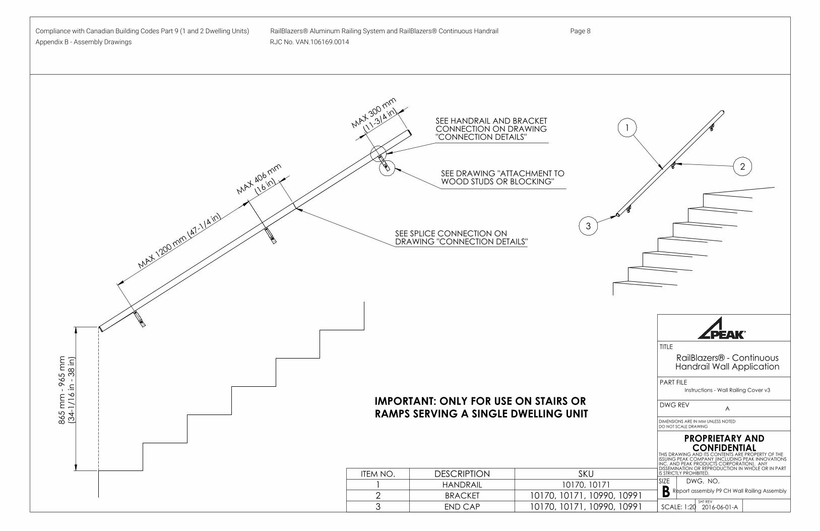
IMPORTANT: ONLY FOR USE ON STAIRS OR RAMPS SERVING A SINGLE DWELLING UNIT
3
2
1
ITEM NO. DESCRIPTION SKU1 HANDRAIL 10170, 101712 BRACKET 10170, 10171, 10990, 109913 END CAP 10170, 10171, 10990, 10991
DIMENSIONS ARE IN MM UNLESS NOTED
TITLE
SIZE
BDWG. NO.
SCALE: 1:20
RailBlazers® - Continuous Handrail Wall Application
Report assembly P9 CH Wall Railing Assembly
DO NOT SCALE DRAWING
Instructions - Wall Railing Cover v3PART FILE
SHT REV2016-06-01-A
DWG REV A
THIS DRAWING AND ITS CONTENTS ARE PROPERTY OF THE ISSUING PEAK COMPANY (INCLUDING PEAK INNOVATIONS INC. AND PEAK PRODUCTS CORPORATION). ANY DISSEMINATION OR REPRODUCTION IN WHOLE OR IN PART IS STRICTLY PROHIBITED.
PROPRIETARY AND CONFIDENTIAL
Compliance with Canadian Building Codes Part 9 (1 and 2 Dwelling Units) RailBlazers® Aluminum Railing System and RailBlazers® Continuous Handrail Page 8 Appendix B - Assembly Drawings RJC No. VAN.106169.0014

2 3 1 4 56
ITEM NO. DESCRIPTION1 BRACKET2 6.4 mm x 79 mm [1/4 x 3-1/8 in] HEX FLANGE BOLT3 39 mm [1-1/2 in] BACKING PLATE4 6.4 mm [1/4 in] LOCK WASHER5 6.4 mm [1/4 in] FLANGE ACORN NUT6 POST
DIMENSIONS ARE IN MM UNLESS NOTED
TITLE
SIZE
BDWG. NO.
SCALE: 1:2
RailBlazers® - Continuous Handrail Post Connection Details
Report assembly P9 CH
DO NOT SCALE DRAWING
Post mount explodedPART FILE
SHT REV2016-06-01-A
DWG REV A
THIS DRAWING AND ITS CONTENTS ARE PROPERTY OF THE ISSUING PEAK COMPANY (INCLUDING PEAK INNOVATIONS INC. AND PEAK PRODUCTS CORPORATION). ANY DISSEMINATION OR REPRODUCTION IN WHOLE OR IN PART IS STRICTLY PROHIBITED.
PROPRIETARY AND CONFIDENTIAL
Compliance with Canadian Building Codes Part 9 (1 and 2 Dwelling Units) RailBlazers® Aluminum Railing System and RailBlazers® Continuous Handrail Page 9 Appendix B - Assembly Drawings RJC No. VAN.106169.0014
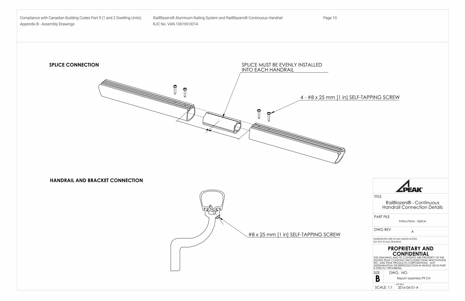
SPLICE MUST BE EVENLY INSTALLED INTO EACH HANDRAIL
SPLICE CONNECTION
4 - #8 x 25 mm [1 in] SELF-TAPPING SCREW
#8 x 25 mm [1 in] SELF-TAPPING SCREW
HANDRAIL AND BRACKET CONNECTION
DIMENSIONS ARE IN MM UNLESS NOTED
TITLE
SIZE
BDWG. NO.
SCALE: 1:1
RailBlazers® - Continuous Handrail Connection Details
Report assembly P9 CH
DO NOT SCALE DRAWING
Instructions - SplicePART FILE
SHT REV2016-06-01-A
DWG REV A
THIS DRAWING AND ITS CONTENTS ARE PROPERTY OF THE ISSUING PEAK COMPANY (INCLUDING PEAK INNOVATIONS INC. AND PEAK PRODUCTS CORPORATION). ANY DISSEMINATION OR REPRODUCTION IN WHOLE OR IN PART IS STRICTLY PROHIBITED.
PROPRIETARY AND CONFIDENTIAL
Compliance with Canadian Building Codes Part 9 (1 and 2 Dwelling Units) RailBlazers® Aluminum Railing System and RailBlazers® Continuous Handrail Page 10 Appendix B - Assembly Drawings RJC No. VAN.106169.0014

MAX 1.2 m (47-1/4 in) MAX 300 mm
(11-3/4 in)A
A
2-8.
5 m
m(1
1/32
in)
10 m
m(1
3/32
in)
20 m
m(2
5/32
in)
SECTION A-A SCALE 1 : 2
Requirements within section 9.8.7.7. of Alberta Building Code 2014, British Columbia Building Code 2012, National Building Code 2015 and Ontario Building Code 2012:
Handrails serving a single dwelling unit attached to wood studs or blocking:a. The attachment points are no more than 1.2 m apart in the horizontal plane,b. The first attachment point at either end is no more than 300 mm from the end of the handrail, andc. The fasteners consist of not less than 2 No. 8 wood screws at each point, penetrating not less than 32 mm into solid wood.
ATTACHMENT TO WOOD STUDS OR BLOCKING
DIMENSIONS ARE IN MM UNLESS NOTED
TITLE
SIZE
BDWG. NO.
SCALE: 1:5
RailBlazers® - Continuous Handrail Wall Attachment
Report assembly P9 CH Wall Connection Details
DO NOT SCALE DRAWING
Report - Wood connectionPART FILE
SHT REV2016-06-01-A
DWG REV A
THIS DRAWING AND ITS CONTENTS ARE PROPERTY OF THE ISSUING PEAK COMPANY (INCLUDING PEAK INNOVATIONS INC. AND PEAK PRODUCTS CORPORATION). ANY DISSEMINATION OR REPRODUCTION IN WHOLE OR IN PART IS STRICTLY PROHIBITED.
PROPRIETARY AND CONFIDENTIAL
Compliance with Canadian Building Codes Part 9 (1 and 2 Dwelling Units) RailBlazers® Aluminum Railing System and RailBlazers® Continuous Handrail Page 11 Appendix B - Assembly Drawings RJC No. VAN.106169.0014

28 mm (1-3/32 in)
2- 7.2 mm
(9/32 in)
UNIVERSAL CONNECTORHORIZONTAL INSTALLATION
SKU: 10900, 10901
MOUNTINGTEMPLATE:
27.5 mm (1-3/32 in)
2-9.5 mm (3/8 in)
24 mm(15/16 in) 2-
9.5 mm (3/8 in)
63.2 mm (2-1/2 in)
38 mm (1-1/2 in)
MOUNTINGTEMPLATE:
WALL MOUNT BRACKETSSKU: 10920, 10921
UNIVERSAL CONNECTORVERTICAL INSTALLATION
SKU: 10900, 10901
DIMENSIONS ARE IN MM UNLESS NOTED
TITLE
SIZE
BDWG. NO.
SCALE: 1:2
RailBlazers® - Railing Brackets and Connectors
Report-brackets RB-CAN
DO NOT SCALE DRAWING
fig-ubrackets-horizPART FILE
SHT REV2016-06-01-A
DWG REV A
THIS DRAWING AND ITS CONTENTS ARE PROPERTY OF THE ISSUING PEAK COMPANY (INCLUDING PEAK INNOVATIONS INC. AND PEAK PRODUCTS CORPORATION). ANY DISSEMINATION OR REPRODUCTION IN WHOLE OR IN PART IS STRICTLY PROHIBITED.
PROPRIETARY AND CONFIDENTIAL
Compliance with Canadian Building Codes Part 9 (1 and 2 Dwelling Units) RailBlazers® Aluminum Railing System and RailBlazers® Continuous Handrail Page 12 Appendix B - Assembly Drawings RJC No. VAN.106169.0014

CORNER FASCIA MOUNT BRACKETSKU: 10960, 10961
LEFT MOUNTINGTEMPLATE:
72 m
m(2
-27/
32 in
) 6- 11.5 mm (7/16 in)
33 mm (1-5/16 in) 33 mm (1-5/16 in)
112 mm(4-13/32 in)
112
mm
(4-1
3/32
in)
MID/STAIR/END FASCIA MOUNT BRACKETSKU: 10970, 10971
MOUNTINGTEMPLATE:
20 mm (25/32 in)
82 m
m (3
-7/3
2 in
)
30 m
m (1
-3/1
6 in
)
4- 11.5 mm(7/16 in)
95 mm (3-3/4 in)
15 m
m (1
9/32
in)
97 m
m (3
-13/
16 in
)
RIGHT MOUNTINGTEMPLATE:
4- 11.5 mm (7/16 in)95 mm (3-3/4 in)
20 mm (25/32 in)
DIMENSIONS ARE IN MM UNLESS NOTED
TITLE
SIZE
BDWG. NO.
SCALE: 1:3
RailBlazers® - Railing Fascia Mount Brackets
Report-brackets RB-CAN
DO NOT SCALE DRAWING
fig-fascia-cornerPART FILE
SHT REV2016-06-01-A
DWG REV A
THIS DRAWING AND ITS CONTENTS ARE PROPERTY OF THE ISSUING PEAK COMPANY (INCLUDING PEAK INNOVATIONS INC. AND PEAK PRODUCTS CORPORATION). ANY DISSEMINATION OR REPRODUCTION IN WHOLE OR IN PART IS STRICTLY PROHIBITED.
PROPRIETARY AND CONFIDENTIAL
Compliance with Canadian Building Codes Part 9 (1 and 2 Dwelling Units) RailBlazers® Aluminum Railing System and RailBlazers® Continuous Handrail Page 13 Appendix B - Assembly Drawings RJC No. VAN.106169.0014

CORNER POSTEND POST MID POST STAIR POST
102
mm
(4 in
)
4 x 9.25 mm (11/32 in)
102 mm (4 in)
78 mm (3-1/16 in)
78
mm
(3-1
/16
in)
12 mm (1/2 in)
12
mm
(1/2
in)
MOUNTINGTEMPLATE
21.
5 m
m (2
7/32
in)
DESCRIPTION SKUEnd Post 10000, 10001Mid Post 10010, 10011
Corner Post 10020, 10021Stair Post 10050, 10051
DIMENSIONS ARE IN MM UNLESS NOTED
TITLE
SIZE
BDWG. NO.
SCALE: 1:8
RailBlazers® Railing Posts
Report-posts RB-CAN
DO NOT SCALE DRAWING
fig-post-corner PABPART FILE
SHT REV2016-06-01-A
DWG REV A
THIS DRAWING AND ITS CONTENTS ARE PROPERTY OF THE ISSUING PEAK COMPANY (INCLUDING PEAK INNOVATIONS INC. AND PEAK PRODUCTS CORPORATION). ANY DISSEMINATION OR REPRODUCTION IN WHOLE OR IN PART IS STRICTLY PROHIBITED.
PROPRIETARY AND CONFIDENTIAL
Compliance with Canadian Building Codes Part 9 (1 and 2 Dwelling Units) RailBlazers® Aluminum Railing System and RailBlazers® Continuous Handrail Page 14 Appendix B - Assembly Drawings RJC No. VAN.106169.0014