HEAVY DUTY MACHINING · Heavy duty machining Heavy duty machining ...
1
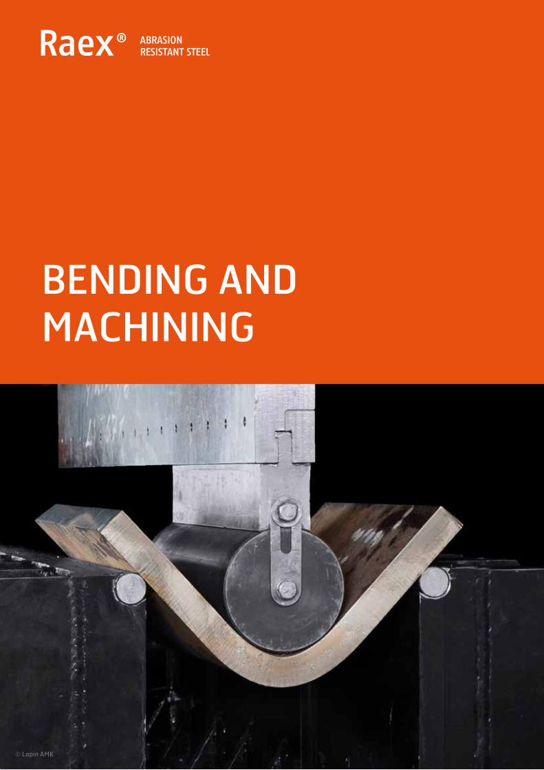
BENDING AND MACHINING
© Lapin AMK

Raex abrasion resistant steel is designed for steel structures that areexposed to abrasive wear and tear. The wear resistance properties ofRaex can significantly prolong the service life of your equipment,saving you time and money. Raex extends the service life of steel structures by cutting downtheir weight in comparison to mild steel. Lighter components increaseload capacity which saves fuel and reduces emissions by reducing the number of trucks in service.
2
YOUR WEARDEMANDSCOVERED
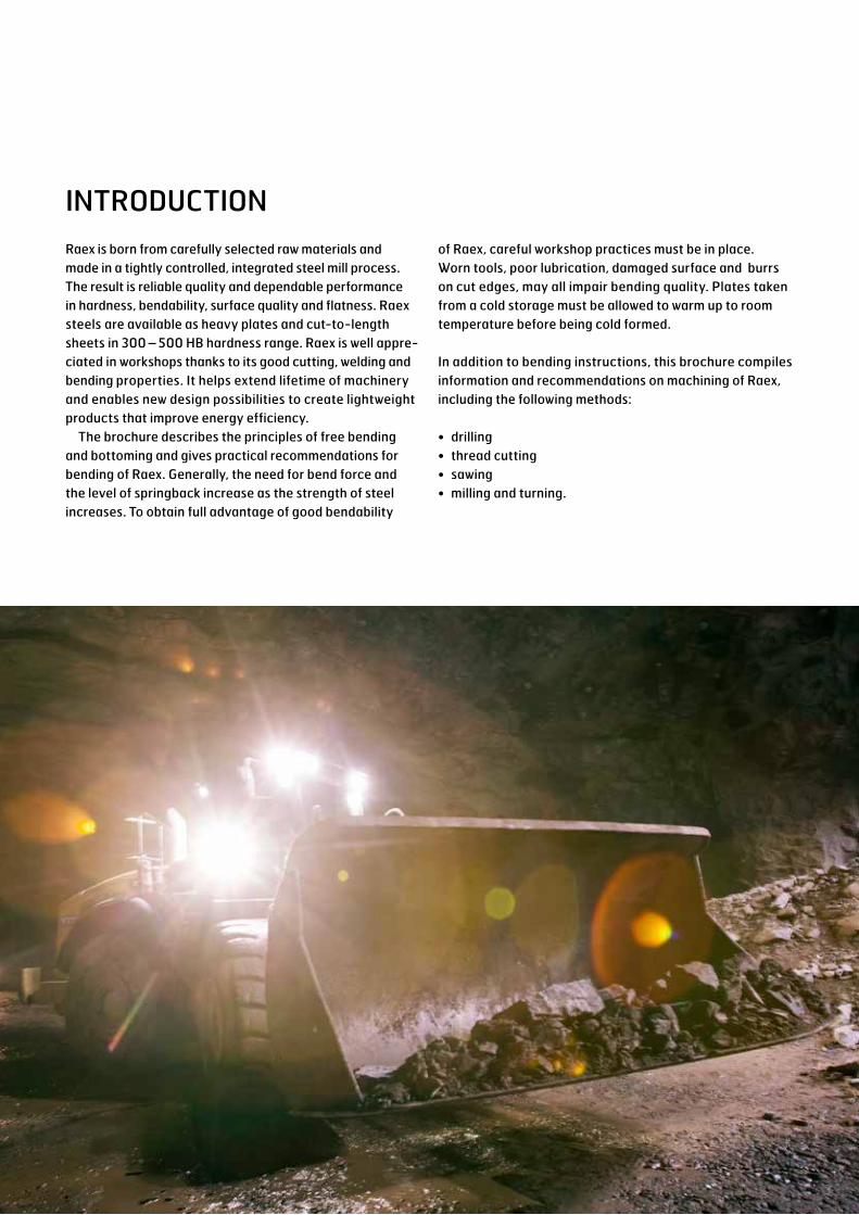
Raex is born from carefully selected raw materials and made in a tightly controlled, integrated steel mill process. The result is reliable quality and dependable performance in hardness, bendability, surface quality and flatness. Raex steels are available as heavy plates and cut-to-length sheets in 300 – 500 HB hardness range. Raex is well appre-ciated in workshops thanks to its good cutting, welding and bending properties. It helps extend lifetime of machinery and enables new design possibilities to create lightweight products that improve energy efficiency.
The brochure describes the principles of free bending and bottoming and gives practical recommendations for bending of Raex. Generally, the need for bend force and the level of springback increase as the strength of steel increases. To obtain full advantage of good bendability
INTRODUCTIONof Raex, careful workshop practices must be in place. Worn tools, poor lubrication, damaged surface and burrs on cut edges, may all impair bending quality. Plates taken from a cold storage must be allowed to warm up to room temperature before being cold formed.
In addition to bending instructions, this brochure compiles information and recommendations on machining of Raex, including the following methods:
• drilling• thread cutting• sawing• milling and turning.
3
4
BENDING METHODSThe plate is bent to the designed angle or free bending radius in a flanging press between the punch and the die.
In free bending, the plate rests on the upper edges of the die gap for the entire duration of the pass. The required bending radius is obtained by adjusting the stroke length (Figure 1). The die gap width can be adjusted.
In bottoming, the stroke length is sufficient for the punch to press the plate entirely against the die. An edge matching that of the punch and die is formed in the plate (Figure 1). The die gap (V-groove) is fixed and its width cannot beadjusted.
PREPARATION BEFORE BENDING• The temperature of the plate must be a minimum of +20°C.• It is recommended to bring plates stored in cold places indoors a day
prior to bending operations.• If required, the area to be bent must be heated using a gas flame.• Preheating to +100 – +200°C reduces the required bending force and
improves bendability in general.• Identify the rolling direction of the plate.• Possible surface defects must be ground away from the tension side face
of the plate.• Grind away defects on the cut edge of a thermally or mechanically cut
plate, at least on the area to be bent.
The contents of this brochure represent general suggestions. SSAB AB accepts no responsibility for their suitability in individual cases. The user is therefore responsible to make the necessary adaptations to the conditions in each individual case.

Free bending
Punch
Die
Bottoming
Punch
Die
FIGURE 1. BENDING METHODS AND TOOLS.
FIGURE 2. BENDING TRANSVERSE TO THE ROLLING DIRECTION IS RECOMMENDED.
Bending area
Bend line
Die width (W)
Plate rolling direction
Plate before bending
Die entry radius, Rd
t
Punch radius, Rp
5The contents of this brochure represent general suggestions. SSAB AB accepts no responsibility for their suitability in individual cases. The user is therefore responsible to make the necessary adaptations to the conditions in each individual case.

BENDING INSTRUCTIONS• Safety instructions must be followed in bending.• The need for bending force, springback effect and
the permitted bending radius increase as the strength of the steel increases.
• The widest possible bending radius must be used.• Flanging must be made in a single pass.• The best possible workshop expertise can be obtained
by combining theoretical and empirical data.• Bending values are defined on the basis of test bending
taking the degree of the springback effect into con- sideration.
• The springback effect in Raex 400 is 8° – 25° and in Raex 500 15° – 35°, depending on bending tool parameters. Wider die-gap results in bigger springback.
• Trial tests are always recommended.
In practical bending or flanging, the punch diameter is defined on the basis of steel grade, plate thickness and bend radius. Table 1 presents the punch diameter (D), plate thickness (t) and internal bend radius (R) for Raex 400, Raex 450 and Raex 500.
BENDING INSTRUCTIONS FOR THE WORKSHOP
BENDING FORCE
P =b • t2 • Rm
(W-Rd-Rp) • 9800
The bending force (P, in metric tons) needed when bending of steel plates can be estimated using the following formula:
P = Bend force, metric tonst = Plate thickness, mmW = Die width, mm (figure 2)b = Bend length, mmRm = Tensile strength, MPa (table 2)Rd = Die entry radius, mm (figure 2)Rp = Punch radius, mm
6The contents of this brochure represent general suggestions. SSAB AB accepts no responsibility for their suitability in individual cases. The user is therefore responsible to make the necessary adaptations to the conditions in each individual case.
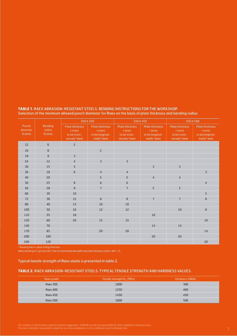
TABLE 1. RAEX ABRASION-RESISTANT STEELS. BENDING INSTRUCTIONS FOR THE WORKSHOP. Selection of the minimum allowed punch diameter for Raex on the basis of plate thickness and bending radius
Punch diameter D (mm)
Bending radius R (mm)
RAEX 400 RAEX 450 RAEX 500
Plate thickness t (mm)
to be trans- versely1) bent
Plate thickness t (mm)
to be longitud- inally1) bent
Plate thickness t (mm)
to be trans- versely1) bent
Plate thickness t (mm)
to be longitud- inally1) bent
Plate thickness t (mm)
to be trans- versely1) bent
Plate thickness t (mm)
to be longitud- inally1) bent
12 6 2
16 8 2
18 9 3
24 12 4 3 3
30 15 5 3 3
36 18 6 4 4 3
40 20 5 5 4 4
50 25 8 6 6 4
56 28 9 7 7 5 5
60 30 10 5
72 36 12 8 8 7 7 6
80 40 13 10 10
100 50 16 12 12 10 8
110 55 18 10
120 60 20 15 15 10
140 70 14 14
170 85 20 20 14
200 100 20 20
240 120 20
1) Bending line vs. plate rolling direction.
When bending in V groove (90°) the recommended die width and plate thickness ratio is W/t ≈ 15.
Typical tensile strength of Raex steels is presented in table 2.
TABLE 2. RAEX ABRASION-RESISTANT STEELS. TYPICAL TENSILE STRENGTH AND HARDNESS VALUES.
Raex grade Tensile strength Rm (MPa) Hardness (HBW)
Raex 300 1000 300
Raex 400 1250 400
Raex 450 1450 450
Raex 500 1600 500
7The contents of this brochure represent general suggestions. SSAB AB accepts no responsibility for their suitability in individual cases. The user is therefore responsible to make the necessary adaptations to the conditions in each individual case.

8
MINIMUM BEND RADIUSTable 3 shows the minimum bending radii for Raex abrasion-resistant steels. In practical bending or flanging in the engineering works, it is recommendable to use inside bending radii which are greater than the minimum allowed bendingradii. In addition to the steel plate, the quality of the bend depends on the bending tools and the performance of the work. Successful bending requires good engineering workshop technology from the steel product processor. Worn-out tools, insufficient lubrication, scratches on the steel surface and burr compromise the quality of the cold forming process.
TABLE 3. RAEX ABRASION-RESISTANT STEELS. MINIMUM BEND RADIUS R, BEND ANGLE ≤ 90.
Raex grade Product formThickness
(mm)R/t minimum
transverseR/t minimumlongitudinal
Die opening widthW/t minimum
Raex 300 Sheet 2 – 8 3 3 12
Raex 400Sheet 2 – 8 3 4 12
Plate 6 – 20 3 4 14
Raex 450Sheet 2.5 – 8 3 4 12
Plate 6 – 20 4 5 14
Raex 500Sheet 3 – 6.5 3.5 4 14
Plate 6 – 20 5 6 14
The contents of this brochure represent general suggestions. SSAB AB accepts no responsibility for their suitability in individual cases. The user is therefore responsible to make the necessary adaptations to the conditions in each individual case.
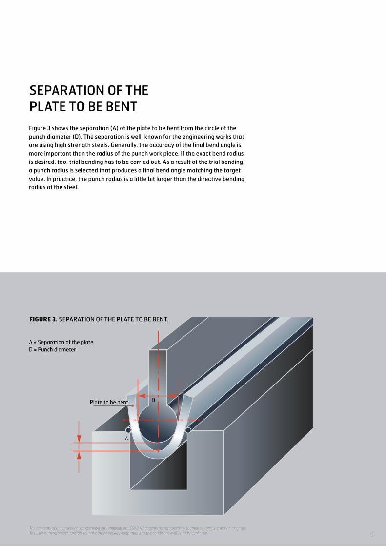
A
D
A = Separation of the plateD = Punch diameter
Plate to be bent
Figure 3 shows the separation (A) of the plate to be bent from the circle of the punch diameter (D). The separation is well-known for the engineering works that are using high strength steels. Generally, the accuracy of the final bend angle is more important than the radius of the punch work piece. If the exact bend radius is desired, too, trial bending has to be carried out. As a result of the trial bending, a punch radius is selected that produces a final bend angle matching the target value. In practice, the punch radius is a little bit larger than the directive bending radius of the steel.
SEPARATION OF THE PLATE TO BE BENT
FIGURE 3. SEPARATION OF THE PLATE TO BE BENT.
9The contents of this brochure represent general suggestions. SSAB AB accepts no responsibility for their suitability in individual cases. The user is therefore responsible to make the necessary adaptations to the conditions in each individual case.

10
MACHINABILITYGENERAL INSTRUCTIONS FOR MACHINING:
• The machine must be rigid and stable.• Clamp the workpiece as rigidly and close to the area
to be cut as possible.• Long tool holders and spindle overhangs must be
avoided.• No harmful vibration may occur during any stage
of machining.• Particular caution must be exercised when starting
a cutting operation.• Grind away any rough edges on a thermally cut plate
in the area where the first cut is started.• Sufficient feed and depth of cut must be used.• Provide a generous flow of cutting fluid.• Lower the cutting speed in dry cutting.• When machining abrasion-resistant steels on a
regular basis, hard metal tools should be selected using the manufacturers’ data sheets.
DRILLINGRecommended drilling parameters for non-alloyed high-speed steel (HSS) drills and cobalt-alloyed HSS drills are presented in tables 4, 5 and 6. Additionally, recommended drilling parameters for the steel grade Raex 500 using solid cemented carbide drills are included in table 6. Raex 400 and Raex 450 can be drilled with HSS drills. For drilling of Raex 500 hard metal drills are recommended.
GENERAL INSTRUCTIONS FOR DRILLING:
• The drilling machine has to be rigid and stable in order to minimize vibrations.
• Clamb the workpiece securely and close to the area to be machined.
• Short-hole drills are recommended.• The service life of the drilling tool can be prolonged
by decreasing the feed.• Provide an abundant supply of cutting fluid.
The contents of this brochure represent general suggestions. SSAB AB accepts no responsibility for their suitability in individual cases. The user is therefore responsible to make the necessary adaptations to the conditions in each individual case.

TABLE 4. RAEX 400. RECOMMENDED DRILLING PARAMETERS.
Drill diameter(mm)
Feed rate (mm/rev)
Feed rate (mm/minute)
Cutting speed (m/minute)
Speed of rotation (rpm)
Uncoated HSS drill
5 0.10 60 – 80 9 – 12 600 – 800
15 0.20 40 – 50 9 – 12 200 – 250
25 0.25 30 – 40 9 – 12 110 – 150
Uncoated HSS-Co drill
5 0.10 70 – 100 12 – 15 800 – 950
15 0.20 50 – 70 12 – 15 250 – 320
25 0.20 25 – 30 9 – 12 110 – 150
TABLE 5. RAEX 450. RECOMMENDED DRILLING PARAMETERS.
Drill diameter(mm)
Feed rate (mm/rev)
Feed rate (mm/minute)
Cutting speed (m/minute)
Speed of rotation (rpm)
Uncoated HSS drill
5 0.08 40 – 50 8 – 10 500 – 650
15 0.20 35 – 45 8 – 10 170 – 210
25 0.25 25 – 35 8 – 10 100 – 130
Uncoated HSS-Co drill
5 0.10 60 – 75 8 – 10 600 – 750
15 0.20 35 – 45 8 – 10 170 – 210
25 0.20 15 – 20 6 – 8 75 – 100
TABLE 6. RAEX 500. RECOMMENDED DRILLING PARAMETERS.
Drill diameter(mm)
Feed rate (mm/rev)
Feed rate (mm/minute)
Cutting speed (m/minute)
Speed of rotation (rpm)
Uncoated HSS drill
5 0.10 25 4 250
15 0.15 15 4 85
25 0.15 8 4 50
Uncoated HSS-Co drill5 0.10 25 – 35 4 – 6 250 – 380
15 0.15 15 – 20 4 – 6 80 – 130
Solid cemented carbide drill 16 0.15 120 40 800
11The contents of this brochure represent general suggestions. SSAB AB accepts no responsibility for their suitability in individual cases. The user is therefore responsible to make the necessary adaptations to the conditions in each individual case.

MACHINE TAPPINGFor thread cutting, micro-alloyed HSS-E or cobalt-alloyed HSS-Co taps with four cutting edges are recommended. The best result is obtained by using cutting oil or paste. When the strength of the joint is not critical, thread holes approximately 3 – 5 percent larger than the standard values are recommended. A larger hole diameter will significantly increase tool life. During the threading pass, unobstructed chip removal must be secured without reversing the tool or alternating the direction of rotation. Shallow holes should be threaded using appropriate taps, see table 7.
TABLE 7. RAEX. MACHINE TAPPING, HSS-E TAP.
Cutting speed (m/min)
Tap size
M10Spindle speed
(rpm)
M16Spindle speed
(rpm)
M20Spindle speed
(rpm)
M24Spindle speed
(rpm)
M30Spindle speed
(rpm)
M42Spindle speed
(rpm)
Raex 400 3.6 115 80 63 53 42 30
Raex 500 1.6 50 40 32 25 21 15
12The contents of this brochure represent general suggestions. SSAB AB accepts no responsibility for their suitability in individual cases. The user is therefore responsible to make the necessary adaptations to the conditions in each individual case.
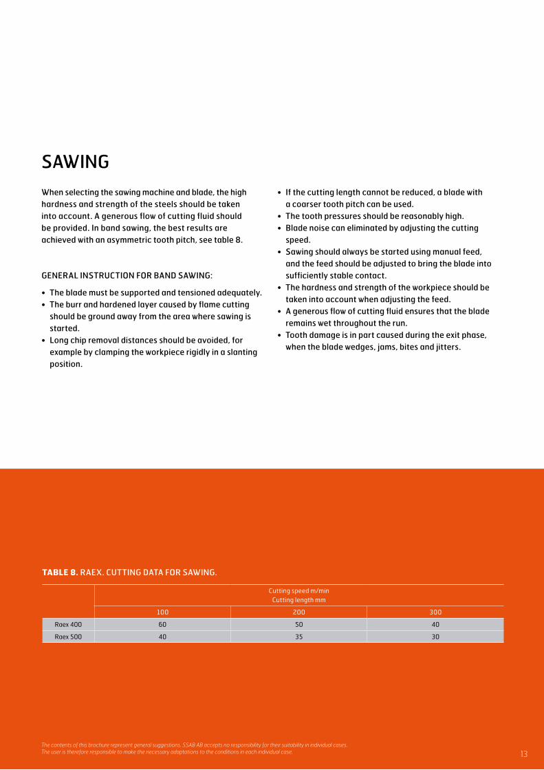
SAWINGWhen selecting the sawing machine and blade, the high hardness and strength of the steels should be taken into account. A generous flow of cutting fluid should be provided. In band sawing, the best results are achieved with an asymmetric tooth pitch, see table 8.
GENERAL INSTRUCTION FOR BAND SAWING:
• The blade must be supported and tensioned adequately.• The burr and hardened layer caused by flame cutting
should be ground away from the area where sawing is started.
• Long chip removal distances should be avoided, for example by clamping the workpiece rigidly in a slanting position.
TABLE 8. RAEX. CUTTING DATA FOR SAWING.
Cutting speed m/minCutting length mm
100 200 300
Raex 400 60 50 40
Raex 500 40 35 30
• If the cutting length cannot be reduced, a blade with a coarser tooth pitch can be used.
• The tooth pressures should be reasonably high.• Blade noise can eliminated by adjusting the cutting
speed.• Sawing should always be started using manual feed,
and the feed should be adjusted to bring the blade into sufficiently stable contact.
• The hardness and strength of the workpiece should be taken into account when adjusting the feed.
• A generous flow of cutting fluid ensures that the blade remains wet throughout the run.
• Tooth damage is in part caused during the exit phase, when the blade wedges, jams, bites and jitters.
13The contents of this brochure represent general suggestions. SSAB AB accepts no responsibility for their suitability in individual cases. The user is therefore responsible to make the necessary adaptations to the conditions in each individual case.
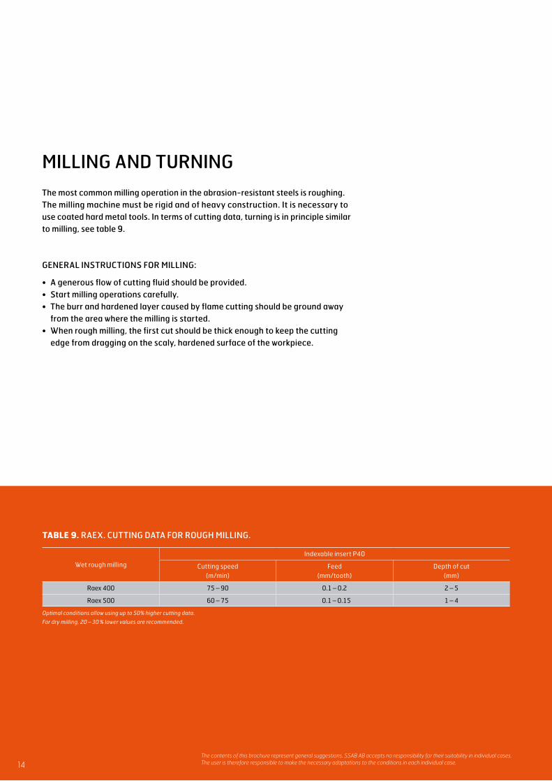
The most common milling operation in the abrasion-resistant steels is roughing. The milling machine must be rigid and of heavy construction. It is necessary to use coated hard metal tools. In terms of cutting data, turning is in principle similar to milling, see table 9.
GENERAL INSTRUCTIONS FOR MILLING:
• A generous flow of cutting fluid should be provided.• Start milling operations carefully.• The burr and hardened layer caused by flame cutting should be ground away
from the area where the milling is started.• When rough milling, the first cut should be thick enough to keep the cutting
edge from dragging on the scaly, hardened surface of the workpiece.
TABLE 9. RAEX. CUTTING DATA FOR ROUGH MILLING.
Wet rough milling
Indexable insert P40
Cutting speed (m/min)
Feed (mm/tooth)
Depth of cut (mm)
Raex 400 75 – 90 0.1 – 0.2 2 – 5
Raex 500 60 – 75 0.1 – 0.15 1 – 4
Optimal conditions allow using up to 50% higher cutting data.
For dry milling, 20 – 30 % lower values are recommended.
MILLING AND TURNING
14The contents of this brochure represent general suggestions. SSAB AB accepts no responsibility for their suitability in individual cases. The user is therefore responsible to make the necessary adaptations to the conditions in each individual case.
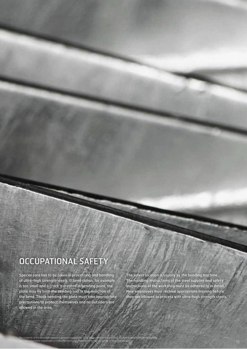
OCCUPATIONAL SAFETYSpecial care has to be taken in processing and handling of ultra-high strength steels. If bend radius, for example, is too small and a crack is created in bending point, the plate may fly from the bending tool in the direction of the bend. Those bending the plate must take appropriate precautions to protect themselves and no outsiders are allowed in the area.
The safest location is usually by the bending machine. The handling instructions of the steel supplier and safety instructions of the workshop must be adhered to in detail. New employees must receive appropriate training before they are allowed to process with ultra-high strength steels.
15The contents of this brochure represent general suggestions. SSAB AB accepts no responsibility for their suitability in individual cases. The user is therefore responsible to make the necessary adaptations to the conditions in each individual case.

CONTACT
300
2-en
-Rae
x-B
endi
ng a
nd m
achi
ning
-V2
.0-2
016
-Co
nfet
ti. Ö
ster
berg
s.