RADIOISOTOPE DOSE CALIBRATOR OWNER’S MANUAL€¦ · CAPINTEC, INC CRC®-15R PREFACE Thank you for...
140
CRC ® -15R RADIOISOTOPE DOSE CALIBRATOR OWNER’S MANUAL Capintec, Inc. Sales and Marketing and Customer Support 6 Arrow Road Ramsey, NJ 07446 Phone (800) ASK-4CRC Fax (201) 825-1336 Capintec, Inc. Service Center 540 Alpha Drive Pittsburgh, PA 15238 Phone (800) 227-6832 Fax (412) 963-0610 Copyright © 1990, Capintec, Inc. CRC ® is a registered trademark of Capintec, Inc. U.S. Patents - 3,748,476 and 3,840,745 ALL RIGHTS RESERVED Manual Stock No. 9250-0038 Rev. W – November 2004
Transcript of RADIOISOTOPE DOSE CALIBRATOR OWNER’S MANUAL€¦ · CAPINTEC, INC CRC®-15R PREFACE Thank you for...

CRC®-15R
RADIOISOTOPE DOSE CALIBRATOR
OWNER’S MANUAL
Capintec, Inc. Sales and Marketing
and Customer Support 6 Arrow Road
Ramsey, NJ 07446 Phone (800) ASK-4CRC
Fax (201) 825-1336
Capintec, Inc. Service Center
540 Alpha Drive Pittsburgh, PA 15238 Phone (800) 227-6832 Fax (412) 963-0610
Copyright© 1990, Capintec, Inc.
CRC® is a registered trademark of Capintec, Inc.
U.S. Patents - 3,748,476 and 3,840,745 ALL RIGHTS RESERVED
Manual Stock No. 9250-0038
Rev. W – November 2004


CAPINTEC, INC CRC®-15R
TABLE OF CONTENTS PREFACE
SAFETY ................................................................................................................................1-1 SYMBOL DEFINITIONS ....................................................................................................1-1 WARNING AND CAUTION LABELS .................................................................................1-2 CAUTIONS AND NOTES ..................................................................................................1-3 GENERAL SAFETY TIPS..................................................................................................1-5
FUNCTIONAL & TECHNICAL DESCRIPTION....................................................................2-1 FUNCTIONAL DESCRIPTION ..........................................................................................2-1
Program Organization....................................................................................................2-2 Overall Program Flow................................................................................................2-2 Utility Programs .........................................................................................................2-2
TECHNICAL DESCRIPTION.............................................................................................2-3 On / Off Switch...............................................................................................................2-3 Warm Up Period.............................................................................................................2-3 Environment Requirements............................................................................................2-3
Operational ................................................................................................................2-3 Storage......................................................................................................................2-3
Power Requirements......................................................................................................2-4 Line Voltage...............................................................................................................2-4 Line Filter...................................................................................................................2-4 Ground Current..........................................................................................................2-4 Power Connector and Cable .....................................................................................2-4
Dimensions ....................................................................................................................2-4 Performance ..................................................................................................................2-5 Regulatory Listings.........................................................................................................2-5
EMC...........................................................................................................................2-5 Electrical ....................................................................................................................2-5 ETL Listed .................................................................................................................2-5
GENERAL OPERATING INSTRUCTIONS ..........................................................................3-1 GENERAL..........................................................................................................................3-1 KEYBOARD.......................................................................................................................3-1
Layout ............................................................................................................................3-1 Key Usage .....................................................................................................................3-2
NUCLIDE Keys: Co57, Ga67, Tc99m, F18, In111, I 123, I 131, Xe133, Tl201........3-2 USER Keys: U1, U2, U3, U4 ....................................................................................3-2 NUCL Key..................................................................................................................3-2 CAL # Key .................................................................................................................3-2 TIME Key...................................................................................................................3-2 TEST Key ..................................................................................................................3-2 BKG Key....................................................................................................................3-2 HOME Key.................................................................................................................3-2
November 04 TABLE OF CONTENTS TOC-1

CAPINTEC, INC CRC®-15R
UTIL Key ...................................................................................................................3-2 MO ASSAY Key ........................................................................................................3-2 NUMBER/LETTER Keys...........................................................................................3-2 CE Key ......................................................................................................................3-3 ENTER Key...............................................................................................................3-3 ARROW Keys ( and )..........................................................................................3-3 Ci / Bq Key ................................................................................................................3-3
Entering Data.................................................................................................................3-3 Numeric Data ............................................................................................................3-3 Alphanumeric Data....................................................................................................3-3
Making Menu Selections................................................................................................3-4 Responding to Questions (Yes or No) ...........................................................................3-4
SYSTEM SETUP ..................................................................................................................4-1 GENERAL .........................................................................................................................4-1 RECEIVING CONDITION EXAMINATION........................................................................4-1 UNPACKING AND INSTALLATION..................................................................................4-1 ASSEMBLY .......................................................................................................................4-2 ENVIRONMENT REQUIREMENTS..................................................................................4-4 POWER REQUIREMENTS...............................................................................................4-4
Readout .........................................................................................................................4-4 Printers ..........................................................................................................................4-4 Remote Display Unit ......................................................................................................4-5
TURN ON PROCEDURES................................................................................................4-5 GENERAL OPERATIONAL SETUP..................................................................................4-5 ACCEPTANCE TESTING .................................................................................................4-6
Diagnostics Test ............................................................................................................4-6 Daily Test.......................................................................................................................4-7 Accuracy Test ................................................................................................................4-7
OPERATIONAL SUMMARY..............................................................................................4-7
SYSTEM INITIALIZATION ...................................................................................................5-1 GENERAL .........................................................................................................................5-1 ENTERING DATE AND TIME ...........................................................................................5-1 CHOOSING Ci or Bq.........................................................................................................5-3 INPUTTING TEST SOURCE DATA..................................................................................5-4
Source Verification.........................................................................................................5-5 Entering Serial Number .................................................................................................5-6 Entering Calibration Date...............................................................................................5-6 Entering Calibration Activity...........................................................................................5-7 Indicating Daily Usage ...................................................................................................5-7 Confirming Calibration Data...........................................................................................5-8
CONSTANCY TEST SOURCE .........................................................................................5-8 USER KEY ASSIGNMENT................................................................................................5-9
Selecting User Key ......................................................................................................5-10 Current Assignment Display ........................................................................................5-10 Nuclide Name Assignment ..........................................................................................5-11 Assignment Confirmation.............................................................................................5-11
ADDING A NUCLIDE ......................................................................................................5-11
TOC-2 TABLE OF CONTENTS November 04

CAPINTEC, INC CRC®-15R
Entering Nuclide Name ................................................................................................5-12 Entering Half-Life .........................................................................................................5-12 Entering Calibration Number........................................................................................5-13 Determining Calibration Numbers ................................................................................5-13
DELETING A NUCLIDE...................................................................................................5-14 CHANGING CALIBRATION NUMBERS .........................................................................5-14
Entering User Defined Calibration Number..................................................................5-14 Restoring Original Calibration Number ........................................................................5-15
SELECTING MOLY ASSAY METHOD............................................................................5-16 VIEWING AND CHANGING MO/TC LIMIT .....................................................................5-17 PRINTING........................................................................................................................5-18
Printer Power Requirements ........................................................................................5-18 Printer Selection...........................................................................................................5-18 Okidata Menu Setup ....................................................................................................5-19
ACCEPTANCE & QUALITY ASSURANCE TESTS.............................................................6-1 GENERAL..........................................................................................................................6-1 ACCEPTANCE TESTS......................................................................................................6-1
Diagnostic Test ..............................................................................................................6-1 Daily Test .......................................................................................................................6-1 Accuracy Test ................................................................................................................6-2
QUALITY ASSURANCE TESTS .......................................................................................6-4 Daily Tests .....................................................................................................................6-4 Contamination Test ........................................................................................................6-4
QUARTERLY TESTS ........................................................................................................6-4 Daily and Diagnostic Tests.............................................................................................6-5 Accuracy Test ................................................................................................................6-5 Linearity Test .................................................................................................................6-7
Decay Method ...........................................................................................................6-7 Sleeve Method...........................................................................................................6-7 Proportional Method ..................................................................................................6-7
TESTS...................................................................................................................................7-1 GENERAL..........................................................................................................................7-1 DAILY TEST ......................................................................................................................7-1
Auto Zero .......................................................................................................................7-1 Background....................................................................................................................7-3 System Test ...................................................................................................................7-4 Data Check ....................................................................................................................7-5 Accuracy Test and Constancy Test ...............................................................................7-5
Accuracy and Constancy Test in Daily Test ..............................................................7-5 Accuracy Test from Menu..........................................................................................7-7
DIAGNOSTIC TEST ..........................................................................................................7-7 Diagnostics Printout .......................................................................................................7-9
MEASUREMENT PROCEDURES........................................................................................8-1 GENERAL..........................................................................................................................8-1 MEASUREMENT PROCEDURES ....................................................................................8-1
November 04 TABLE OF CONTENTS TOC-3

CAPINTEC, INC CRC®-15R
General Activity Measurement Procedure .....................................................................8-1 Specifying Nuclide .........................................................................................................8-1
Pre-Set Nuclide Key:.................................................................................................8-2 User Key: ..................................................................................................................8-2 NUCL Key: ................................................................................................................8-2
Entering Calibration Number .........................................................................................8-2 Selecting Range ............................................................................................................8-3
ACTIVITY AT A DIFFERENT TIME...................................................................................8-3 PRINTING A RECORD OF THE MEASUREMENT ..........................................................8-4
OKIDATA Printer ...........................................................................................................8-4 Ticket Chosen: ..........................................................................................................8-4 Single Line Chosen: ..................................................................................................8-4
Roll Printer .....................................................................................................................8-5 Slip Printer .....................................................................................................................8-5
MOLY ASSAY ...................................................................................................................8-5 Mo99 Background..........................................................................................................8-5 Mo99 Assay ...................................................................................................................8-7 Tc99m Assay .................................................................................................................8-8 Moly Assay Results .......................................................................................................8-9
CALCULATION UTILITIES ..................................................................................................9-1 GENERAL .........................................................................................................................9-1 CONVERSION BETWEEN Ci and Bq (Ci ↔ Bq).............................................................9-1 DECAY CALCULATION....................................................................................................9-2
Calculations for Nuclides in Memory .............................................................................9-2 Calculations for Nuclides not in Memory .......................................................................9-4
CLEANING AND MAINTENANCE.....................................................................................10-1 GENERAL .......................................................................................................................10-1 CLEANING INSTRUCTIONS ..........................................................................................10-1 PREVENTATIVE MAINTENANCE..................................................................................10-2 SERVICING.....................................................................................................................10-2 DISPOSAL ......................................................................................................................10-2 FUSE SERVICING ..........................................................................................................10-3
Readout Fuses ............................................................................................................10-3 Printer Fuse .................................................................................................................10-3
TROUBLESHOOTING ....................................................................................................10-4 Nothing appears on the display. ..................................................................................10-4 Nothing happens when any key is pressed. ................................................................10-4 Buzzer buzzes continuously. .......................................................................................10-4 High background indication. ........................................................................................10-4 Zero activity is indicated with a source in the well. ......................................................10-4 Readings appear overly noisy for low activities. ..........................................................10-4 Indication of significant negative activity. .....................................................................10-4 Printer prints junk or prints with incorrect spacing. ......................................................10-4 Print head hangs up when printing tickets. ..................................................................10-5 Printer will not respond. ...............................................................................................10-5
ACCESSORIES AND REPLACEMENT PARTS.............................................................10-5 SHIPPING .......................................................................................................................10-6
TOC-4 TABLE OF CONTENTS November 04
CAPINTEC, INC CRC®-15R
APPENDIX I – Principle of the Calibrator
APPENDIX II – Table of Calibration Setting Numbers
APPENDIX III – Multiplication Factors for Non-Equilibrium Radioisotopes
APPENDIX IV – Operational Summary
INDEX
WARRANTY
DECLARATION OF CONFORMITY
November 04 TABLE OF CONTENTS TOC-5


CAPINTEC, INC CRC®-15R
PREFACE Thank you for purchasing the Capintec, Inc. CRC®-15R Radioisotope Dose Calibrator. Every effort has been made to insure that the information in this document is complete, accurate, and up-to-date. Capintec, Inc. assumes no responsibility for the results of errors beyond its control. Mention of products manufactured by other companies does not necessarily constitute endorsement by Capintec, Inc. Please address any comments pertaining to this manual to: CAPINTEC, Inc. 540 Alpha Drive Pittsburgh, PA 15238 Phone (412) 963-1988 Fax (412) 963-0610 CRC®-15R and CII are registered trademarks of Capintec, Inc.
SYSTEM DESCRIPTION The basic CRC®-15R Radioisotope Dose Calibrator consists of the following:
• Display Unit • Chamber • Power Cord • Printer (optional)
YEAR 2000 COMPLIANCE The CRC®-15R measurement systems contain information technology that accurately processes date and time data between the years 1999 and 2000. These products, when used in combination with products purchased from other manufacturers whose products properly exchange date and time information, will accurately process the date and time. All future products are committed to meeting the same Year 2000 compliance.
MEDICAL EQUIPMENT SAFETY CLASSIFICATION
• CLASS I EQUIPMENT energized from an external power source.
• TYPE B EQUIPMENT with no applied parts to the patient.
• Ordinary EQUIPMENT without protection against the ingress of water.
• Suitable for CONTINUOUS OPERATION.
• NOT suitable for use in an OXYGEN or a FLAMMABLE ENVIRONMENT.
November 04 PREFACE i
CAPINTEC, INC CRC®-15R
ELECTROMAGNETIC INTERFERENCE POTENTIAL This equipment complies fully with interference immunity requirements of the standard EN 60601-1-2 “Medical electrical equipment: Part 1: General safety requirements; 2. Supplementary standard: Electromagnetic compatibility”. This equipment generates radio frequency energy and, if not installed and used in accordance with the instructions, may cause harmful interference to nearby devices. However, there is no guarantee that interference will not occur in a particular installation. If this equipment does cause harmful interference, the user is encouraged to try to correct the interference by one of the following measures:
• Increase the separation between the equipment and the affected device.
• Plug the unit into an outlet on a circuit different from that to which the affected device is connected.
If this fails to correct the problem, please contact Capintec.
IMPORTANT SAFETY INFORMATION The CRC®-15R measurement system has been carefully designed to give you years of safe and reliable performance. As with all electrical equipment, however, there are basic precautions you must observe to avoid injuring yourself, the patient or damaging the equipment.
• Follow the unpacking and assembly instructions document, and read this manual carefully before using this equipment. Be sure to save all provided documents for future reference.
• Understand all warning and caution labels as explained in the “SAFETY” chapter before operating this equipment.
ii PREFACE November 04

CAPINTEC, INC CRC®-15R
CHAPTER 1
SAFETY These warnings and instructions for use form an integral part of the CRC®-15R and must therefore be kept available for consultation at all times. Precise compliance with the instructions is an essential condition for normal use, correct application and thus safety of the user.
SYMBOL DEFINITIONS
Protective Earth Ground
Functional Earth Ground
Attention: consult owner’s manual for further information
Fuse
AC Voltage
“ON” (power)
“OFF” (power)
November 04 SAFETY 1 - 1

CAPINTEC, INC CRC®-15R
WARNING AND CAUTION LABELS Located on the back of the Readout Unit is a label, (see Fig. 1-1), providing the system power requirements and the replacement fuse values for power line voltages. Please refer to CHAPTER 10: CLEANING AND MAINTENANCE for instructions on how to change the fuses of the CRC®-15R. A fire hazard may exist if the wrong size of fuse is installed.
Figure 1-1 Located on the bottom of the chamber is 2 labels. The first label, (see Figure 1-2), contains statements denoting not to remove the cover because there are no adjustments that the user can perform in the chamber.
Figure 1-2 The second label (Figure 1-3) pertains to the electrical safety of the chamber. It is necessary because of the high voltage present (approximately 180 volts) on the PC board installed in the chamber. A screwdriver is necessary to remove the cover.
Figure 1-3
1 - 2 SAFETY November 04

CAPINTEC, INC CRC®-15R
CAUTIONS AND NOTES CAUTION
Only qualified/trained personnel should operate or service this unit.
CAUTION High voltage is present inside the chamber (up to 180 Volts). Due to the presence of this high voltage, opening the covers with the system plugged in may be hazardous. Refer all servicing to qualified personnel.
CAUTION No internal adjustments inside the chamber may be performed by the user within the conditions of the warranty, except for changing the fuse. Due to the presence of high voltages, opening the cover with the system plugged in may be hazardous. Refer all servicing to qualified personnel.
CAUTION Never use the calibrator without the well liner in place. Liners are inexpensive and easy to replace. A contaminated chamber is a very costly mistake. If unit becomes contaminated remove liner and clean unit as stated in CHAPTER 10: CLEANING AND MAINTENANCE before operating.
CAUTION Care must be exercised when moving the instrument or when maintenance is performed. The shielded cylinder is heavy (13.6 kg or 30 lb.). In order to provide the required sensitivity, the wall of the ionization chamber is extremely thin and the chamber is filled with pressurized gas. It is therefore, essential to avoid mechanical shock or vibration of any kind.
CAUTION When working with a heavy sample (especially a CapMac or Moly Assay Canister) always lower it gently into the chamber well. Dropping any heavy object into the well can cause permanent, expensive damage.
CAUTION The use of multiplication and division factors in Calibration Numbers is only to maintain a degree of consistency with other Capintec dose calibrators. The CRC®-15R is a direct reading instrument. If multiplication or division is required, the arithmetic will be done by the system. The actual activity is displayed. DO NOT apply these factors to the displayed activity yourself.
CAUTION It is desirable to leave the unit powered at all times in order to prevent moisture absorption and to maintain the stability of the instrument (especially if the instrument is subjected to high humidity or low temperature).
November 04 SAFETY 1 - 3

CAPINTEC, INC CRC®-15R
CAUTION The sensitivity of the chamber is somewhat dependent upon the vertical position of the sample within the well. All calibrations were done with a Standard Sample placed in the supplied sample holder (dipper). It should be noted that in this configuration, the sample is not quite at the bottom of the well. If, for any reason, you make a measurement without using the dipper, be sure that the sample is in the correct vertical position. Both the CapMac and the Standard Moly Assay Canister maintain the same position as the dipper.
CAUTION This equipment generates radio frequency energy and, if not installed and used in accordance with the instructions, may cause harmful Electromagnetic Interference (EMI) to nearby devices. However, there is no guarantee that interference will not occur in a particular installation.
CAUTION If any printer other than one of the three models supplied by Capintec is used, the safety of the unit may be compromised or Electromagnetic Interference (EMI) may be introduced into other devices located in the same general area as the CRC®-15R or the CRC®-15R may become susceptible to EMI.
CAUTION The unit contains lead. Appropriate caution should be taken if the interior of the unit is exposed. The unit should be disposed of in accordance with local and national regulations.
CAUTION The unit contains a Lithium Battery. This should be disposed of in accordance with local and national regulations.
CAUTION The user should always verify the validity of any measurement or test result in order to minimize measurement errors.
NOTE It is recommended that periodic (every five years) re-calibration of the unit be performed by Capintec to guarantee that the instrument's high reliability is maintained.
1 - 4 SAFETY November 04

CAPINTEC, INC CRC®-15R
GENERAL SAFETY TIPS • Unplug the equipment before cleaning it. Use only a damp cloth; do not use liquids or
aerosol cleaners.
• To protect the equipment from overheating, do not use the equipment directly in front of a radiator or heat register.
• Do not use the equipment near water, or spill liquids of any kind into the equipment.
• Be sure that your power source matches the rating listed on the CRC®-15R calibrator.
• The CRC®-15R power cord has a grounded, 3-prong plug as a safety feature, and it will only fit into a grounded outlet. Do not use an adapter to defeat the grounding.
• To avoid damaging the power cord, do not place anything on it or place it where it will be stepped on. If the cord becomes damaged, replace it immediately.
• Aside from the routine maintenance described in this manual, do not try to service this equipment yourself. Do not make any adjustments other than those outlined in this manual, as you may in-validate the calibration or cause damage requiring extensive repair work. Refer servicing to qualified service personnel.
November 04 SAFETY 1 - 5


CAPINTEC, INC CRC®-15R
CHAPTER 2
FUNCTIONAL & TECHNICAL DESCRIPTION
FUNCTIONAL DESCRIPTION The CRC®-15R provides a precise, accurate, fast and very convenient method of measuring the activity of a radioisotope sample for Nuclear Medicine and Brachytherapy. The activity of the sample will be displayed with a proper unit when a sample of unknown strength (activity) of a known radioisotope is placed in the ionization chamber and the correct calibration number is selected. The sample must be placed in the same geometry as the reference source used to determine the calibration number by using the appropriate source holder. Note: For a detailed description of the basic principles of the calibrator, see to APPENDIX I:
PRINCIPLE OF THE CALIBRATOR. Activity measurements are performed by the state of the art electronic circuits in conjunction with an ionization chamber possessing extremely high sensitivity and stability. The effects of the sample container, sample volume, and activity concentration are minimized by optimizing the counting geometries. Nine preset nuclide keys are provided for the most often used radioisotopes. Four user assignable nuclide keys are provided for commonly used radioisotopes that do not have a preset nuclide key. Assays may be made reliably in the Chamber, from as low as 1 microcurie (0.1 megabequerel) for most radioisotopes to as high as 8 curies [200 giga (109) Becquerel] of Tc99m. The 6cm diameter and 25cm deep ionization chamber well allows convenient measurements of virtually any radioisotope geometry in clinical use including whole generators, syringes and seed trains. The external shield of the ionization chamber protects users from exposure to intensive radiation and reduces the effect from background radiation on low-level measurements.
November 04 FUCTIONAL & TECHNICAL DESCRIPTION 2 - 1

CAPINTEC, INC CRC®-15R
Program Organization Overall Program Flow
When the power is turned on, the Sign-On Screen appears. When the ENTER key is pressed, the Measurement Screen is displayed and the CRC®-15R begins measuring the activity in the Chamber.
Utility Programs Utility Programs can be accessed by pressing UTIL key from the Measurement Screen. Figure 2-1 illustrates utilities available from the Utility Menu.
ChamberMeasurement
Screen
UTILKey
Ci - BqConversion
DecayCalculation
Diagnostics
Setup
Time
Ci / Bq
Printing
Other
EnterPassword
(last 3digits ofSerial
Number)
User Keys
Test Sources
Mo Assay
Nuclide Data Add Nuclide
DeleteNuclide
CalibrationNumbers
convert from Ci to Bq or Bq to Ci
calculate activity at another date/time
confirm all the programs, memories and setups
reset date and time
Ci only, Bq only, User selectable
select printer
assign nuclides to User keysfor Chamber measurement
enter Test Source data
choose CAPMAC or Canisterenter Mo/Tc limit
add nuclide data
delete nuclide dataadded by user
enter new Cal #restore original Cal #
Figure 2-1 Program Flow
2 - 2 FUCTIONAL & TECHNICAL DESCRIPTION November 04

CAPINTEC, INC CRC®-15R
TECHNICAL DESCRIPTION On / Off Switch The on/off switch (I = on; = off) is located on the back of the instrument. Warm Up Period Approximately 30 minutes should be allowed for the instrument to stabilize. While the instrument is warming up, it is strongly recommended that you become familiar with the CRC®-15R. Environment Requirements
Operational The instrument should be located where the level of the background radiation is as low and as constant as possible. The instrument should be located where the temperature is stable within a range of +50°F to +85°F (+10°C to +30°C) and the maximum relative humidity is 90% non-condensing to warrant maximum reliability and accuracy. The instrument should be located where the barometric pressure is within a range of 27 – 31 inches of mercury (91 – 105 kilopascals).
Storage The instrument should be stored where the temperature is stable and the range is from +39°F to +110°F (+4°C to +43°C) and the maximum relative humidity is 90% non-condensing to warrant maximum reliability. The instrument should be stored where the barometric pressure is within a range of 15 – 33 inches of mercury (51 – 112 kilopascals).
CAUTION
If these environmental requirements are not followed, the instrument may display erroneous readings.
November 04 FUCTIONAL & TECHNICAL DESCRIPTION 2 - 3

CAPINTEC, INC CRC®-15R
Power Requirements
CAUTION If the input voltage to the following items is not within the stated limits, the unit may not
function correctly or may be damaged.
Line Voltage Readout
100-240VAC, 120mA, 50/60Hz Printers
Okidata Microline 320 120VAC, 60Hz, 0.9A or 230/240VAC, 50/60Hz, 0.5A
Epson TM-295II Slip Printer (optional) Input: 100-240VAC, 50/60Hz, 1.2A; Output: +24VDC, 0.8A
Epson TM-U200D Roll Printer (optional) Input: 120VAC, 60Hz, 0.45A; Output: 33VDC, 1.2A or Input: 220VAC, 50/60Hz, 1.2A; Output: +24VDC, 0.8A
Remote Display Unit Input: 90~264VAC, 47-63Hz, 0.40A; Output: +5.0 VDC, 2.4A
Line Filter
Line filter is provided internally. Use of a filtered line is recommended if excessive line noise is anticipated.
Ground Current less than 0.5mA
Power Connector and Cable A grounded 3-prong plug cord for the instrument which is approved for use at the user's site must be used. Interconnection of devices must be made using the cables supplied with the instrument.
Dimensions Console: Height 12.1cm (4.75in)
Width 25.4cm (10.0in) Depth 26.7cm (10.5in) Weight 1.8kg (3.9lb)
2 - 4 FUCTIONAL & TECHNICAL DESCRIPTION November 04

CAPINTEC, INC CRC®-15R
Well Chamber: Height 41.9cm (16.5in) Diameter 17.2cm (6.76in) Weight 13.6kg (30lb) Well Dia. 6.1cm (2.4in) Well Depth 25.4cm (10.0in) Cable Length1 2.4m (8ft)
Cables: Power 1.8m (6ft)
Printer2 1.8m (6ft) Performance Measurement Range:
Maximum Activity (Tc99m in CAPMAC) 300 GBq (8 Ci) Maximum Activity (Tc99m) 240 GBq (6.5 Ci)
Resolution .001 MBq (.01 µCi) Electrometer Accuracy3 better than ±2% System Precision better than ± 0.1% of FSD System Linearity within ±2% Response Time (Low activity sample) within 4 or 16 sec. Response Time (All other samples) within ±1% Regulatory Listings The CRC®-15R has been independently tested and is manufactured in compliance with the following Standards:
EMC • European Union Norm EN 60601-1-2: Medical Electrical Equipment – Part 1
General Requirements for Safety – Section 1.2 Collateral Standard: Electromagnetic Compatibility – Requirements and Tests
Electrical
• European Union Norm EN 60601-1: Medical Electrical Equipment – Part 1 General Requirements for Safety
• European Union Norm EN 60601-1-1: Medical Electrical Equipment – Part 1 General Requirements for Safety – Section 1.1 Collateral Standard: Safety Requirements for Medical Electrical Systems
ETL Listed
1 Longer cables are available. Consult factory. 2 Optional 3 Overall accuracy is determined by the calibration for the specific nuclide and the sample configuration and the accuracies of the standard sources used for calibration of the electrometer.
November 04 FUCTIONAL & TECHNICAL DESCRIPTION 2 - 5

CAPINTEC, INC CRC®-15R
CHAPTER 3
GENERAL OPERATING INSTRUCTIONS
GENERAL This section describes general operating procedures: the keyboard, how to enter data and make menu selections.
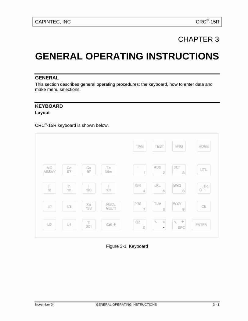
KEYBOARD Layout CRC®-15R keyboard is shown below.
Figure 3-1 Keyboard
November 04 GENERAL OPERATING INSTRUCTIONS 3 - 1

CAPINTEC, INC CRC®-15R
Key Usage General usage of keys is briefly described. Specific key usage will be given in the appropriate sections.
NUCLIDE Keys: Co57, Ga67, Tc99m, F18, In111, I 123, I 131, Xe133, Tl201 Pressing one of these keys selects that nuclide.
USER Keys: U1, U2, U3, U4 Any nuclide in memory may be assigned to each User Key. When a key is assigned, it acts just like a Nuclide Key.
NUCL Key Pressing this key allows the user to select any nuclide in memory (including nuclides added by the user). The nuclide is chosen using the number/letter keys.
CAL # Key Pressing this key allows the user to input a calibration number to be used for the current measurement.
TIME Key After pressing this key, a time and date is input. The activity at the input time of the source being measured is displayed under the current activity along with the input time and date.
TEST Key Pressing this key brings up the Test Menu.
BKG Key Pressing this key steps the user through the Background Measurement.
HOME Key Pressing this key will return the user to the Measurement Screen. If this key is pressed before ending the task being performed, the task will be terminated without being finished (e.g. entered data will not be stored and previous values are maintained).
UTIL Key Pressing this key brings up the Utility Menu.
MO ASSAY Key Pressing this key steps the user through a Molyassay Procedure.
NUMBER/LETTER Keys The keys with Numbers and Letters on them are used to enter data. The decimal point is the UP ARROW ( ) key.
3 - 2 GENERAL OPERATING INSTRUCTIONS November 04

CAPINTEC, INC CRC®-15R
CE Key
This is the Clear Entry key and is used to erase the last character when entering data.
ENTER Key This is used to accept entered data and print a record of the measurement.
ARROW Keys ( and ) When alpha numeric input is being entered, the Arrow keys are used to scroll through the possible values on each number/letter key. During a Chamber measurement, the arrows are used to change the precision of the displayed measurement for low activity. When a multi-field entry is being made (e.g. date, time, activity, half-life) the arrows are used to move to the next field or to change the value of the unit.
Ci / Bq Key Pressing this key toggles the measurement between Curies and Becquerels. It is only active if USER SELECTABLE has been chosen for Ci/Bq.
Entering Data
Numeric Data Numeric data is entered via the NUMBER/LETTER keys on the right hand side of the keyboard. The decimal point is on the same key as the UP ARROW ( ). If the entry must be an integer, the decimal point will not be allowed. Press CE to erase the last digit entered. Press ENTER when a correct entry has been made.
Alphanumeric Data Alphanumeric data (numbers and letters) are also entered via the NUMBER/LETTER keys. When a NUMBER/LETTER key is pressed, the number appears. Use the ARROW keys to change the number into one of the letters on the same key. When the UP ARROW ( ) is pressed, the letters appear in the clockwise direction. When the DOWN ARROW ( ) is pressed, the letters appear in the counter clockwise direction.
November 04 GENERAL OPERATING INSTRUCTIONS 3 - 3

CAPINTEC, INC CRC®-15R
Making Menu Selections All menus appear with a number in front of each selection. To make a selection, press the NUMBER/LETTER key corresponding to the desired selection. Responding to Questions (Yes or No) There are several occasions where the user is asked a question which is to be answered Yes or No. Press Y (9, WXY) for Yes. Press N (6, MNO) for No.
3 - 4 GENERAL OPERATING INSTRUCTIONS November 04

CAPINTEC, INC CRC®-15R
CHAPTER 4
SYSTEM SETUP
GENERAL Initial installation and checkout procedures are described in this section.
RECEIVING CONDITION EXAMINATION Be sure to verify that the shipping carton is received in good condition, i.e., no damage should be visible and the box should be dry and clean. Should the instrument be received in a damaged condition, save the shipping container and the packing material and request an immediate inspection by the carrier. Capintec, Inc. is not responsible for the damage, which occurs during shipment but will make every effort to help obtain restitution from the carrier.
UNPACKING AND INSTALLATION The instrument is packed and shipped as a complete unit. All the accessories are contained in the carton. (If an optional printer or remote display is included, they will be in separate cartons) The instrument is shipped in a plastic bag in order to provide a dry and clean environment during shipment.
CAUTION Be sure the instrument has reached room temperature prior to opening the bag.
(Leave the box in the room 4 hours before opening it.)
1. Remove all outer packing material and tapes. The shipping and packing material should be saved for future use.
2. The following equipment should be found upon unpacking:
• Readout Unit • Chamber and Liner/Dipper • Power Cord • Remote Display and cable (if ordered) • Printer (if ordered)
o OKIDATA MICROLINE 320, or o EPSON SLIP PRINTER, or o EPSON ROLL PRINTER
November 04 SYSTEM SETUP 4 - 1

CAPINTEC, INC CRC®-15R
The Printer should have the following accessories:
• Power Supply • Printer Ribbon • Communications Cable • Roll Paper (If Roll printer ordered) • Tickets (If Ticket printer ordered)
Note: If Test Sources are ordered, they will be shipped separately.
3. Be sure to remove all tape and protective material from the instrument prior to connecting to the power line.
ASSEMBLY
Figure 4-1
1. Verify that all power switches (Readout, Printer, Remote Display) are in the “OFF” or “0” position. (Note: If using the Slip-Ticket printer, please unplug from AC Power)
2. Connect the Chamber Cable to the connector at the rear of the CRC®-15R Readout
labeled “CHAMBER”.
3. Attach the Power Cable to the receptacle on the Power Module located on the back of the Readout Unit.
4 - 2 SYSTEM SETUP November 04

CAPINTEC, INC CRC®-15R
Figure 4-2 Printers
4. Attach the printer cable (one end has a 9 pin “D” connector, the other end has a 25 pin “D” connector) to the connector at the rear of the CRC®-15R Readout marked “PRINTER”. Attach the other end to the printer. Note: Do not attach the printer cable to the “RS-232” connector.
5. For each printer type, verify that the correct paper is installed. (Note: the Slip-Ticket printer paper is manually inserted at the time of printing.)
Figure 4-3 Remote Display
6. Connect the Remote Display Cable (both ends have a 9 pin “D” connector) to the connector at the rear of the CRC®-15R labeled “RS-232”. Attach the other end to the Remote Display labeled “DATA”.
November 04 SYSTEM SETUP 4 - 3

CAPINTEC, INC CRC®-15R
Note: Do not attach the Remote Display cable to the “PRINTER” connector.
7. Attach the Remote Display Power Supply to the Remote Display power input jack labeled as “DC IN”.
ENVIRONMENT REQUIREMENTS The instrument should be located where the level of the background radiation is as low and as constant as possible. The instrument should be located where the temperature is stable within a range of 50°F to 85°F (10°C to 30°C) and the maximum relative humidity is 90% non-condensing to warrant maximum reliability and accuracy. The instrument should be located where the barometric pressure is within a range of 27 – 31 inches of mercury (91 – 105 kilopascals).
CAUTION If these environmental requirements are not followed,
the instrument may display erroneous readings.
POWER REQUIREMENTS
CAUTION If the input voltage to the following items is not within the stated limits,
the unit may not function correctly or may be damaged. Readout
100-240VAC, 120mA, 50/60Hz
Printers Okidata Microline 320
120VAC, 60Hz, 0.9A or 230/240VAC, 50/60Hz, 0.5A
Epson TM-295II Slip Printer (optional) Input: 100-240VAC, 50/60Hz, 1.2A; Output: +24VDC, 0.8A
Epson TM-U200D Roll Printer (optional) Input: 120VAC, 60Hz, 0.45A; Output: 33VDC, 1.2A or Input: 220VAC, 50/60Hz, 1.2A; Output: +24VDC, 0.8A
4 - 4 SYSTEM SETUP November 04

CAPINTEC, INC CRC®-15R
Remote Display Unit Input: 90-264VAC, 47-63Hz, 0.40A; Output: +5.0 VDC, 2.4A
TURN ON PROCEDURES 1. Be sure the interconnecting cable from the detector assembly is properly plugged into
the back of the main unit.
2. Confirm the power requirements of the instrument.
3. Be sure the power switch is off. (Push lower part of the toggle switch next to the power receptor located on the rear of the main unit.)
4. Plug the power plug into a grounded three-wire outlet of the specified power line.
5. Turn on the Display Unit using the power switch located at the rear of the unit.
6. The unit should now display the CRC®-15R start up screen (see Figure 4-4)
CAUTION Accidental connection of the power plug into a DC line or to an AC line which exceeds the
specified voltage may result in catastrophic damage to the instrument's circuits.
CRCR - 15R Rev X.XX
COPYRIGHT 1995 ALL RIGHTS RESERVED
CAPINTEC, INC. NJ USA
ENTER to Continue
Figure 4-4
Note: The screen will display the revision level of the installed software.
GENERAL OPERATIONAL SETUP There are several things that must be done before using the CRC®-15R Radioisotope Dose Calibrator for the first time. The following briefly describes these steps:
• Verify or set the date/time: Although the date and time are set in the factory, you should verify that the date and time are correct for your location. See CHAPTER 5: SYSTEM INITIALIZATION, SECTION: ENTERING DATE AND TIME.
• Select proper units: Ci or Bq. Although the system can be changed at any time, it is recommended that the user set the proper units prior to using the unit to prevent confusion. See CHAPTER 5: SYSTEM INITIALIZATION, SECTION: CHOOSING Ci or Bq.
November 04 SYSTEM SETUP 4 - 5

CAPINTEC, INC CRC®-15R
• Enter Test Source Data: Test sources (standard sources) are used for the accuracy and constancy tests. The accuracy may be tested using Co57, Co60, Ba133, Cs137 or Ra226. There can be a Test Source for each of these nuclides. One or more of the Test Sources must be designated as the source(s) to be used in the Daily Test. See CHAPTER 5: SYSTEM INITIALIZATION, SECTION: ENTERING TEST SOURCE DATA.
• Enter Constancy Test Source: The source for the Constancy Test is chosen from the sources designated as Daily Sources. See CHAPTER 5: SYSTEM INITIALIZATION, SECTION: CONSTANCY TEST SOURCE.
• Verify correct printer setting: The CRC®-15R may be used with three printers: See CHAPTER 5: SYSTEM INITIALIZATION, SECTION: PRINTING.
o OKIDATA MICROLINE 320 o EPSON SLIP PRINTER o EPSON ROLL PRINTER
The following items should be performed before use if required:
• Assign USER Keys: The USER Keys (U1, U2, U3, U4) are a quick way to select a nuclide. A nuclide may be assigned to each key. See CHAPTER 5: SYSTEM INITIALIZATION, SECTION: USER KEY ASSIGNMENT.
• Adding a Nuclide: The CRC®-15R contains nuclide data (name, half-life, calibration number) for over 80 nuclides. The user may add up to 10 nuclides. The name and half-life and calibration number will be added for each one. See CHAPTER 5: SYSTEM INITIALIZATION, SECTION: ADDING A NUCLIDE.
• Changing Calibration Numbers: The user is allowed to change the calibration number of up to 10 built-in nuclides. See CHAPTER 5: SYSTEM INITIALIZATION, SECTION: CHANGING CALIBRATION NUMBERS.
• Selecting Moly Assay Method: Moly Assay can be performed using the CAPMAC or CANISTER. See CHAPTER 5: SYSTEM INITIALIZATION, SECTION: SELECTING MOLY ASSAY METHOD.
• Setting MO/MT Limit: The Mo/Tc limit is set at the factory to 0.15µCi/mCi. The user can change this value. See CHAPTER 5: SYSTEM INITIALIZATION, SECTION: VIEWING OR CHANGING Mo/Tc LIMIT.
ACCEPTANCE TESTING The following tests should be performed prior to operational use of the unit. Diagnostics Test See CHAPTER 7: TESTS, SECTION: DIAGNOSTIC TEST for instructions on how to perform this test.
4 - 6 SYSTEM SETUP November 04

CAPINTEC, INC CRC®-15R
Daily Test See CHAPTER 7: TESTS, SECTION: DAILY TEST for instructions on how to perform this test. Accuracy Test See CHAPTER 7: TESTS, SECTION: DAILY TEST for instructions on how to perform this test.
OPERATIONAL SUMMARY While all users the CRC®-15R are strongly encouraged to read the manual, we realize that there are some who would much rather jump right in. If you are one of those people who say “if all else fails, read the manual”, then refer to Appendix IV. These very simplified instructions are intended to assist in getting you familiar with the basic operation of the CRC®-15R. They are not intended to replace the detailed operating directions in the main body of the manual.
WARNING The General Operational Setup and Acceptance Testing sections above must be performed before referring to Appendix IV. The steps described omit several important tests which may be required by your license and which are also required in order to achieve the full accuracy of the system. Samples measured without the complete start-up procedure having been performed should not be administered to patients.
November 04 SYSTEM SETUP 4 - 7


CAPINTEC, INC CRC®-15R
CHAPTER 5
SYSTEM INITIALIZATION
GENERAL This section describes initialization and parameter setup. All of these functions are accessed via the Main Utility Menu. Press UTIL from the Measurement Screen.
UTILITIES
1. Ci↔Bq CONV 2. DECAY CALC 3. DIAGNOSTICS 4. SETUP
Figure 5-1 Utility Menu
ENTERING DATE AND TIME To view and/or change the date and/or time, press UTIL from the Measurement Screen and then press 4 to select SETUP. The Setup Menu screen should be displayed (Figure 5-2).
SETUP 1. TIME 2. Ci/Bq 3. PRINTING 4. OTHER
Figure 5-2 Setup Menu
Press 1 to view and change the date and/or time. The current date and time will be displayed:
November 04 SYSTEM INITIALIZATION 5 - 1

CAPINTEC, INC CRC®-15R
NOV 09 2004 13:32 CORRECT? Y OR N:
Figure 5-3 Date and Time Verification
If the date or time is not correct, press N. The date/time entry screen will appear with the current date and time displayed in the order hour, minute, day, month, year:
DATE AND TIME h m D M Y 13 32 09 11 04
Figure 5-4 Date / Time Entry Screen
Note that time in input in 24 hour format (e.g., 5:29am is 05 29, 5:29pm is 17 29). Use the arrow keys to highlight the field that you want to change (you can back up by using the left arrow) and then enter the new value. The date and time are checked for validity. If an invalid date or time is entered, a beep sounds and the current date and time are displayed again. Press ENTER when the correct date and time have been entered. The Date and Time Verification Screen will appear with the date and time just entered.
5 - 2 SYSTEM INITIALIZATION November 04

CAPINTEC, INC CRC®-15R
CHOOSING Ci or Bq Measurement results can be displayed in Ci or Bq. The Ci/Bq key is used to switch the measurement result between Ci and Bq. However, in some facilities, it may be decided to disable this feature and allow measurements to be displayed only in Ci or only in Bq. When the system arrives, it is set up to display in Ci and Bq. To enable or disable Ci/Bq switching:
Press UTIL from the Measurement Screen. Press 4 to select SETUP.
From the Setup Menu, press 2 to select Ci/Bq. The current Ci/Bq selection will be shown. The example below is for the default of Selectable (i.e., the user may select Ci or Bq)
Ci / Bq SELECTABLE OK? Y OR N
Figure 5-5 Ci/Bq Verification Screen
If it is correct, press Y. If it is not correct, press N. The Ci/Bq Selection Menu will appear:
1. SET TO Ci 2. SET TO Bq 3. Ci OR Bq
Figure 5-6 Ci/Bq Selection Screen
Press 1, 2 or 3 to make the correct selection. The Ci/Bq Verification Screen will re-appear with the new selection. If 1 was pressed, the selection will be: FIXED TO Ci. If 2 was pressed, the selection will be: FIXED TO Bq. If 3 was pressed, the selection will be: Ci / Bq SELECTABLE.
November 04 SYSTEM INITIALIZATION 5 - 3

CAPINTEC, INC CRC®-15R
INPUTTING TEST SOURCE DATA Test Sources (Standard Sources) are used for the Accuracy and Constancy Tests. The Accuracy and Constancy may be tested using Co57, Co60, Ba133, Cs137 or Ra226. There can be a Test Source for each of these nuclides. One or more of the Test Sources must be designated as the source(s) to be used in the Daily Test. One of the daily sources must be designated as the source to be used for the Constancy Test. The Test Source Menu allows you to enter data for any Test Source and to choose a Constancy Source. When the Measurement Screen appears, press UTIL. From the Utility Menu (Figure 5-1), press 4 to select SETUP. From the Setup Menu (Figure 5-2), press 4 to select OTHER. When the Password Entry Screen appears, input your password (last 3 digits of your serial number) and press ENTER. The Other Menu screen will then appear (Figure 5-7).
1. USER KEYS 2. TEST SOURCES 3. MO ASSAY 4. NUCLIDE DATA
Figure 5-7 Other Menu
Press 2 to select TEST SOURCES. The Test Source Menu will appear:
1. CO57 2. CO60 3. BA133 4. CS137 5. RA226 6. CONSTANCY
Figure 5-8 Test Source Menu
Press 1, 2, 3, 4 or 5 to enter, change or delete the Test Source for the designated nuclide.
5 - 4 SYSTEM INITIALIZATION November 04

CAPINTEC, INC CRC®-15R
Source Verification The previously entered data will be displayed. If there is no data for that nuclide, the message “NO SOURCE” will be displayed. The example below is for Co57 which will be used in the Daily Test.
CO57 S/N: 123456ABC JUN 30 2003 100.0 mCi DAILY OK? Y OR N
Figure 5-9 Test Source Verification
If the data is correct press Y. To change the data, press N. To add a source (if “NO SOURCE”) or delete a source which is no longer being used, press N. If N was pressed and there was data displayed, you will have the opportunity to delete the source:
DO YOU HAVE CO57 ? Y OR N:
Figure 5-10 Source Existence
If you are no longer using the source, press N and it will be deleted. Press Y to enter data for the source.
November 04 SYSTEM INITIALIZATION 5 - 5

CAPINTEC, INC CRC®-15R
Entering Serial Number The serial number may be any combination of 10 numbers and letters.
CO57 ENTER S/N █
Figure 5-11 Entering Serial Number
Follow the directions in CHAPTER 3: GENERAL OPERATING INSTRUCTIONS, SECTION: ALPHANUMERIC DATA for entering alphanumeric data. Press ENTER when a correct serial number has been entered. Entering Calibration Date The calibration date is input next: The Date Entry Screen will appear with the current date displayed in the order: day month year. The day is highlighted.
CO57 CALIBRATED: D M Y 18 03 04
Figure 5-12 Date Entry Screen
The entry format is similar to entering date and time (See CHAPTER 5: SYSTEM INITIALIZATION, SECTION: ENTERING DATE AND TIME) except that only the date is entered. Input the Source calibration date and press ENTER. The date is checked for validity. If an invalid date is entered a beep sounds and the current date is displayed again.
5 - 6 SYSTEM INITIALIZATION November 04

CAPINTEC, INC CRC®-15R
Entering Calibration Activity The calibration activity can now be entered:
CO57 CALIB ACTIVITY: valu unit █ µCi
e
-> to change unit ENTER to accept
Figure 5-13 Entering Activity Screen
Input the value of the calibrated activity and then press the RIGHT ARROW ( ). Use the arrow keys to scroll the activity units: µCi, MBq or mCi. If the value needs to be changed, press the CE key. When the value and unit are correct, press ENTER. Note: The Calibration activity must be less than 1 Ci. The current activity (calibration activity
decayed to the present time) must be greater than the activity in the table below.
Minimum at Current Time
Co57 50. µCi
Co60 50. µCi
Ba133 50. µCi
Cs137 50. µCi
Ra226 10. µCi Indicating Daily Usage You must now indicate whether the source will be used for the Daily Test:
CO57 USE DAILY ? Y OR N
Figure 5-14 Daily Use Screen
November 04 SYSTEM INITIALIZATION 5 - 7

CAPINTEC, INC CRC®-15R
If the source is to be used in the Daily Test, press Y. If it will not be used in the Daily Test, press N. Confirming Calibration Data The Test Source Verification Screen (Figure 5-9) will now be displayed with the data you have just entered. If the data is correct, press Y. If there is any error, press N. If N is pressed, you will be returned to the Source Existence Screen (Figure 5-10).
CONSTANCY TEST SOURCE The source for the Constancy Test is chosen from the sources designated as Daily Sources. (If there are no Daily Sources, the error message “NO DAILY SOURCE WAS CHOSEN – ANY KEY TO CONTINUE” will appear.) To select the source to use in the Constancy Test:
Press UTIL from the Measurement Screen. From the Utility Menu, press 4 to select SETUP. From the Setup Menu, press 4 to select OTHER. When the password entry screen appears, input your password (last 3 digits of your serial number) and press ENTER. Press 2 to select TEST SOURCES. Press 6 to select CONSTANCY.
The source for the Constancy Test is chosen from the sources designated as Daily Sources. If only one Test Source is designated as a Daily Source, it will be set as the Constancy Test Source as shown.
CONSTANCY TEST CO57 Any Key to Continue
Figure 5-15 Constancy Source Verification
If more than one Test Source is designated as a Daily Source and one of the sources was already set as the Constancy Test Source, you will be asked if it is OK. In the example below, Co57 is the current source.
5 - 8 SYSTEM INITIALIZATION November 04

CAPINTEC, INC CRC®-15R
CONSTANCY TEST CO57 OK? Y OR N
Figure 5-16 Constancy Source Verification Screen
If you answer No, you will be asked to select the Constancy Test Source from the Test Sources that were designated as Daily Sources (Figure 5-17). If more than one Test Source is designated as a Daily Source and none of the sources were set as the Constancy Test Source, you will be asked to select one of the Test Sources that were designated as Daily Sources. In the example below, Co57 and Co60 were designated as Daily Sources:
CONSTANCY TEST 1. CO57 2. CO60
Figure 5-17 Constancy Test Source Selection
Enter the number corresponding to the source to be used for the Constancy Test. The Constancy Source Verification screen (Figure 5-16) will reappear showing the selected source.
USER KEY ASSIGNMENT The USER Keys (U1, U2, U3, U4) are a quick way to select a nuclide. A nuclide may be assigned to each key. Press UTIL from Measurement Screen. Press 4 to select SETUP. Press 4 to select OTHER. Input your password (last 3 digits of serial number). From the Other Menu (Figure 5-7), press 1 to select USER KEYS.
November 04 SYSTEM INITIALIZATION 5 - 9

CAPINTEC, INC CRC®-15R
Selecting User Key
SELECT USER KEY U1 TO U4 Any Other Key To Continue Setup
Figure 5-18 User Key Selection Screen
Press the User Key to which a nuclide is to be assigned. Press any other key to exit User Key Assignment. Current Assignment Display The current key assignment will be displayed. In the example, Co60 has been assigned to U1.
U1: CO60 OK? Y OR N
Figure 5-19 User Key Verification Screen
If no assignment has been made, the word NONE will appear after the key name. If the assignment is correct, press Y and you will be returned to User Key Selection Screen. Press N to change the assignment.
5 - 10 SYSTEM INITIALIZATION November 04

CAPINTEC, INC CRC®-15R
Nuclide Name Assignment
SPECIFY NUCLIDE █
Figure 5-20 Nuclide Name Assignment Screen
Press the alphanumeric keys corresponding to the nuclide name. The number on each key will appear. For example, if Cs137 is entered, 27137 will appear. Press ENTER when the nuclide has been specified. To change the assignment to NONE, press ENTER without specifying a nuclide. Assignment Confirmation The User Key Verification Screen will appear with the nuclide just entered. If it is correct, press Y. If it is not correct, press N and Nuclide Name Assignment Screen will re-appear.
ADDING A NUCLIDE The CRC®-15R contains nuclide data (name, half-life, calibration number) for over 80 nuclides. The user may add up to 10 nuclides. The name and half-life and calibration number will be added for each one. Press UTIL from the Measurement Screen. Press 4 to select SETUP. Press 4 to select OTHER. Input your password (last 3 digits of the serial number) and press ENTER. From the Other Menu (Figure 5-7), press 4 to select NUCLIDE DATA.
November 04 SYSTEM INITIALIZATION 5 - 11

CAPINTEC, INC CRC®-15R
1. ADD NUCLIDE 2. DEL NUCLIDE 3. CAL NUMBERS
Figure 5-21 Nuclides Menu
Press 1 to select ADD NUCLIDE. Entering Nuclide Name
TYPE IN NUCLIDE NAME
Figure 5-22 Entering Nuclide Name Screen
User the NUMBER/LETTER keys to input the nuclide name. The first 2 characters will be displayed as letters (use the 1 key for a blank if there is only 1 character in the name) and the next 3 characters as numbers. If the nuclide is in a metastable state, use the Tc99m key on the left of the keyboard for the m. Press ENTER when the nuclide name has been entered. Entering Half-Life
HALF-LIFE: value unit █ MIN -> to change unit ENTER to accept
Figure 5-23 Entering Half-Life Screen
5 - 12 SYSTEM INITIALIZATION November 04

CAPINTEC, INC CRC®-15R
Enter the value of the half-life and then press the RIGHT ARROW ( ). Use the arrow keys to scroll the half-life from Min to Year to Day to Hour. If the value needs to be changed, press the CE key. When the value and unit are correct, press ENTER. Entering Calibration Number
ENTER CALIBRATION # █
Figure 5-24 Enter Calibration Number Screen
Input the calibration number if known. If the calibration number is not known then it can be determined by the following procedure. Determining Calibration Numbers An initial Calibration Number (as an initial starting point choose 450) must be entered into the CRC®-15R for the nuclide. Note: In order to obtain a correct reading for a Vial or Syringe, the supplied liner and dipper
must be used to achieve the correct geometry. If the source is contained in a different type of container, then contact Capintec, Inc. for further assistance.
1. Place the standard source of the nuclide in the chamber and record the displayed
activity. 2. If the displayed activity is higher than the measured/calculated activity of the
standard source, increase the Calibration Number. If the displayed activity is lower than the measured/calculated activity of the standard source, decrease the Calibration Number.
3. Re-measure the activity of the standard source. 4. Continue to increase or decrease the Calibration Number (e.g. repeat steps 2 and 3)
until the displayed activity matches the measured/calculated activity of the standard source.
5. Record the Calibration Number of the nuclide for future reference. 6. Enter the calibration number.
November 04 SYSTEM INITIALIZATION 5 - 13

CAPINTEC, INC CRC®-15R
DELETING A NUCLIDE Any nuclide added by the user may be deleted. When the Nuclide Menu appears, press 2 for DEL NUCLIDE. When “SPECIFY NUCLIDE” appears, specify the nuclide to be deleted via the Number/Letter keys. The name of the nuclide and its half-life will be displayed. If this is the correct nuclide to delete, press Y; if not, press N.
CHANGING CALIBRATION NUMBERS The user is allowed to change the calibration number of up to 10 built-in nuclides. To change a calibration number or restore the original number:
Press UTIL from the Measurement Screen. Press 4 to select SETUP. Press 4 to select OTHER. Enter your password (last 3 digits of the serial number) and press ENTER. From the Other Menu, press 4 to select NUCLIDE DATA.
When the Nuclide Menu appears, press 3, CAL NUMBERS.
CAL NUMBERS CHOOSE NUCLIDE Press NUCL or Pre-set nuclide key or User key
Figure 5-25 Choose Nuclide for User Defined Calibration Number Screen
Choose the nuclide via NUCL key, pre-set nuclide key or user key. Entering User Defined Calibration Number If the nuclide does not have a new calibration number, the following screen appears (example is for Tc99m):
5 - 14 SYSTEM INITIALIZATION November 04
CAPINTEC, INC CRC®-15R
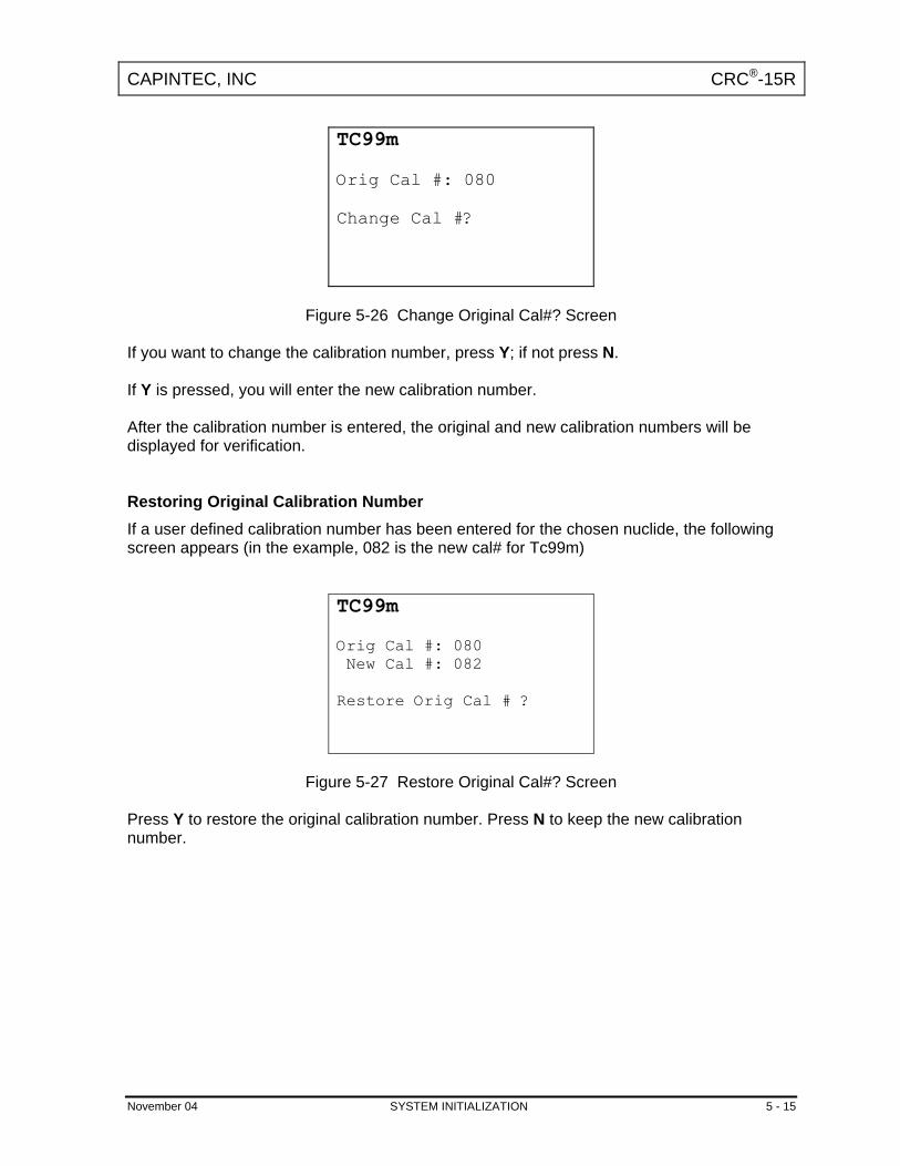
TC99m Orig Cal #: 080 Change Cal #?
Figure 5-26 Change Original Cal#? Screen
If you want to change the calibration number, press Y; if not press N. If Y is pressed, you will enter the new calibration number. After the calibration number is entered, the original and new calibration numbers will be displayed for verification. Restoring Original Calibration Number If a user defined calibration number has been entered for the chosen nuclide, the following screen appears (in the example, 082 is the new cal# for Tc99m)
TC99m Orig Cal #: 080 New Cal #: 082 Restore Orig Cal # ?
Figure 5-27 Restore Original Cal#? Screen
Press Y to restore the original calibration number. Press N to keep the new calibration number.
November 04 SYSTEM INITIALIZATION 5 - 15

CAPINTEC, INC CRC®-15R
SELECTING MOLY ASSAY METHOD Moly Assay can be performed using the CAPMAC or CANISTER. When Moly Assay is chosen, the Moly Assay Method Selection Screen will appear. However, if you always use either CAPMAC or CANISTER, the Moly Assay Method Selection screen can be skipped by making the choice in utilities.
MO ASSAY 1. METHOD 2. MO/TC LIMIT
Figure 5-28 Mo Assay Menu
Press 1 to select METHOD.
CAPMAC FOR MALLINCKRODT Y CAPMAC FOR BRISTOL MYERS Y CANISTER Y OK? Y OR N
Figure 5-29 Moly Assay Method Verification Screen
Press N the change the selection. You will then be asked if you will use “CAPMAC FOR MALLINCKRODT GENERATOR”. Press Y or N. You will next be asked if you will use “CAPMAC FOR BRISTOL MYERS GENERATOR”. Press Y or N. You will next be asked if you will use “CANISTER”. Press Y or N. The Moly Assay Method Verification Screen will reappear. Press Y if the selection is correct. Press N to change the selection.
5 - 16 SYSTEM INITIALIZATION November 04

CAPINTEC, INC CRC®-15R
VIEWING AND CHANGING MO/TC LIMIT The Mo/Tc limit is set at the factory to 0.150µCi/mCi. This value can be changed by the user. From the Moly Assay Menu, press 2 to select MO/TC LIMIT. The current value will be displayed:
MO/TC LIMIT: 0.150µCi/mCi OK? Y OR N
Figure 5-30 Mo/Tc Limit Verification Screen
Press Y to keep the value. Press N to change the value.
INPUT MO/TC LIMIT IN µCi/mCi █
Figure 5-31 Mo/Tc Limit Entry Screen
Input the new value and press ENTER. You will be returned to the Mo/Tc Limit Verification Screen. Note: If Bq had been chosen before entering Utilities, the Mo/Tc limit would be displayed
and entered in MBq/GBq.
November 04 SYSTEM INITIALIZATION 5 - 17

CAPINTEC, INC CRC®-15R
PRINTING CAUTION
If any printer other than one of the three models supplied by Capintec is used, Electromagnetic Interference (EMI) may be introduced into other devices located in the same
general area as the CRC®-15R. The CRC®-15R may be used with three printers:
• OKIDATA MICROLINE 320 • EPSON TM-295II SLIP PRINTER • EPSON TM-U200D ROLL PRINTER
Printer Power Requirements Okidata Microline 320
120VAC, 60Hz or 230/240VAC, 50/60Hz
Epson TM-295II Slip Printer (optional) Input: 100-240VAC, 50/60Hz, 1.2A; Output: +24VDC, 0.8A
Epson TM-U200D Roll Printer (optional) Input: 120VAC, 60Hz, 0.45A; Output: 33VDC, 1.2A or Input: 220VAC, 50/60Hz, 1.2A; Output: +24VDC, 0.8A
Printer Selection If the OKIDATA 320 is used, the calibration measurement can be printed on a ticket or as a single line. To view and/or change the selected printer (and the type of measurement printout if OKIDATA is used): Press UTIL from the Measurement Screen and then press 4 to select SETUP. When the Setup Menu (Figure 5-2) appears, press 3 to select PRINTING. The currently selected printer will be displayed. If OKIDATA is selected, “TICKET” or “ONE LINE” will be displayed. You will be asked if the display is correct. If the display is not correct, press N (no). The Printer Selection Screen will appear:
5 - 18 SYSTEM INITIALIZATION November 04

CAPINTEC, INC CRC®-15R
PRINTER IS 1. SLIP-TICKET 2. ROLL 3. OKI 4. NONE
Figure 5-32 Printer Selection Menu
Press the number corresponding to your printer, or press 4 for NONE if you do not have a printer. If OKI is selected, you must now choose to print the measurement as a TICKET or a SINGLE LINE:
PRINT MEASUREMENT ON 1. TICKET 2. ONE LINE
Figure 5-33 Printout Selection Menu
Select the type of measurement printout. After selecting the printer (and measurement printout) your selection will be displayed for verification. Okidata Menu Setup As it comes from the factory, the Okidata printer should be set-up to function properly with the CRC®-15R. Should you experience printer difficulties, such as not printing, improper print spacing, printing the wrong characters, etc., make sure that the printer Setup is exactly as indicated in Figure 5-34. If any differences are found, they must be corrected. The buttons referred to are all located on the front panel of the printer. The Paper Lever is on the right side of the top surface of the printer near the paper roller. To print and correct the Setup:
1 Make sure that the form paper is properly loaded in the printer.
2 Press the SEL button (to take printer off-line).
3 Press SHIFT + MENU (SEL) to enter the Setup Menu.
November 04 SYSTEM INITIALIZATION 5 - 19

CAPINTEC, INC CRC®-15R
4 Press the PRINT button and the entire Setup listing will print.
5 If there are no differences between what just printed and Figure 5-34 go to step 10.
6 Press the GROUP button. The first line of the first group of lines of the Setup will print.
7 If all lines in the group just printed match the corresponding lines in Figure 5-34, repeat step 6 for the next group.
8 If any line in the group just printed does not match the corresponding line in Figure 5-34, it must be corrected. For example, to change the Baud Rate to 4800:
A. Press the GROUP button until Serial I/F is printed.
B. Press the ITEM button until Baud Rate is printed.
C. Press the SET button until 4800 BPS is printed.
9 If any differences remain, return to step 6 for the next group.
10 Press the SHIFT + MENU (SEL) buttons to return to SEL (on-line).
Note: The Setup printout shown in Figure 5-34 is for example only. Your printer
Setup may differ slightly from that shown. Verify that the settings, which are the same between your Setup and that shown, concur.
5 - 20 SYSTEM INITIALIZATION November 04

CAPINTEC, INC CRC®-15R
Figure 5-34 Listing of the Turbo OKIDATA 320 Printer Set-Up Data
Printer Control Emulation Mode IBM PPR Font Print Mode Utility Font DRAFT Mode HSD Font Pitch 10 CPI Font Proportional Spacing No Font Style Normal Font Size Single Symbol Sets Character Set Set I Symbol Sets Language Set American Symbol Sets Zero Character Slashed Symbol Sets Code Page USA Rear Feed Line Spacing 8 LPI Rear Feed Form Tear-Off Off Read Feed Skip Over Perforation No Rear Feed Page Length 11” Bottom Feed Line Spacing 8 LPI Bottom Feed Form Tear-Off Off Bottom Feed Skip Over Perforation No Bottom Feed Page Length 11” Top Feed Line Spacing 8 LPI Top Feed Bottom Margin Valid Top Feed Page Length 11” Top Feed Wait Time 1 sec Top Feed Page Length Control by Actual Page Length Set-Up Graphics Uni-directional Set-Up Receive Buffer Size 16K Set-Up Paper Out Override No Set-Up Print Registration 0
||||||||||||||||||||||||||||||||||||||||||||||| SET |||||| SHIFT+SET ||||||||||||||||||| <----- -----> Set-Up Operator Panel Functions Full Operation Set-Up Reset Inhibit Yes Set-Up Print Suppress Effective No Set-Up Auto LF No Set-Up Auto CR No Set-Up SI Select Pitch (10CPI) 17.1 CPI Set-Up SI Select Pitch (12CPI) 12 CPI Set-Up Time Out Print Valid Set-Up Auto Select No Set-Up Centering Position DEFAULT Set-Up ESC SI Pitch 17.1 CPI Parallel I/F I-Prime Buffer Print Parallel I/F Pin 18 +5v Serial I/F Parity None Serial I/F Serial Data 7/8 Bits 8 bits Serial I/F Protocol Ready/Busy Serial I/F Diagnostic Test No Serial I/F Busy Line SSD- Serial I/F Baud Rate 4800 BPS Serial I/F DSR Signal Invalid Serial I/F DTR Signal Ready on Power Up Serial I/F Busy Time 200 ms
November 04 SYSTEM INITIALIZATION 5 - 21


CAPINTEC, INC CRC®-15R
CHAPTER 6
ACCEPTANCE & QUALITY ASSURANCE TESTS
GENERAL To insure proper operation of the CRC®-15R, the following tests should be preformed at the indicated intervals.
ACCEPTANCE TESTS The following tests must be preformed in the following order before the initial use of the CRC®-15R:
• Diagnostic Test • Daily Test • Accuracy (for those nuclides that are not used in the Daily Test)
Diagnostic Test When DIAGNOSTICS is selected, the system diagnostic testing will begin. The instrument's memories and the programs are checked (this takes about 1 to 2 minutes) and the results printed and displayed. If any of these tests (RAM, PROM or EEPROM) fail, contact Capintec’s Authorized Service Center. See CHAPTER 7: TESTS, SECTION: DIAGNOSTIC TEST for detailed instructions. Daily Test The Daily Tests should be conducted at the beginning of each working day, prior to measuring any samples, which will be administered to patients. These tests consist of an Auto Zero operation, a Background Adjustment, a System Test, a Data Check, an Accuracy Test, and a Constancy Test. Consider using one or more sources of different photon energy and activity for these tests. See CHAPTER 7: TESTS, SECTION: DAILY TEST for detailed instructions. When TEST is pressed from the Measurement Screen, the Test Menu appears:
November 04 ACCEPTANCE & QUALITY ASSURANCE TESTS 6 - 1

CAPINTEC, INC CRC®-15R
TESTS 1. DAILY 2. SYSTEM 3. ACCURACY
Figure 6-1 Test Menu
Press the 1 key to begin the Daily Test. When the test is complete, if a printer is connected to the system, a report is printed. An example of the Daily Test Report is illustrated in Figure 6-2. If no printer is available, you may record the data by hand. Copies of the completed reports (either printed or hand written) should be retained in a safe place. Accuracy Test If your Accuracy Test setup (CHAPTER 7: TESTS, SECTION: ACCURACY and CONSTANCY TEST) includes nuclides that are not used in the Daily Tests, you should perform the Accuracy Test with those nuclides. It will not be necessary to repeat the test for those nuclides which were included in the Daily Test.
6 - 2 ACCEPTANCE & QUALITY ASSURANCE TESTS November 04

CAPINTEC, INC CRC®-15R
CRC-15R RADIOISOTOPE DOSE CALIBRATOR Nov. 11,2004 13:26 S/N Main Unit: 123456 Rev: 4.00 Capintec, Inc. USA Chamber: 456789 Printer: 258741 DAILY TESTS: ZERO: -0.05 mV BACKGROUND: .35µCi SYSTEM TEST: 160.2 volts DATA CHECK: ALL OK ACCURACY TEST: Source: Co57 Cs137 Serial #: EPOXY-VIAL ABCDEFGHIJ Stand. Source(S): 2.36 mCi 111.4 µCi Measured As (M): 2.36 mCi 112.3 µCi Deviation(M-S)/S: -0.1% 0.9% Daily test report. CONSTANCY TEST: Standard Source: Co57 S/N: EPOXY-VIAL Nuclide Activity CO57 2.36 mCi GA67 2.51 mCi TC99m 2.81 mCi C 11 860. µCi IN111 1.200 mCi I 123 1.29 mCi I 131 1.97 mCi N 13 .86 mCi CR51 25.1 mCi XE133 1.70 mCi TA179 2.27 mCi CO60 .43 mCi TL201 1.60 mCi MOCAP 16.12 mCi TCCAP 3.65 mCi SR85 1.67 mCi HG203 2.61 mCi F 18 .89 mCi IN113m 2.88 mCi AU199 3.36 mCi
_________________________________ signature By : 77
Figure 6-2 Daily Test Report
November 04 ACCEPTANCE & QUALITY ASSURANCE TESTS 6 - 3

CAPINTEC, INC CRC®-15R
QUALITY ASSURANCE TESTS Daily Tests The Daily Tests should be conducted at the beginning of each working day, prior to measuring any samples, which will be administered to patients. These tests consist of an Auto Zero operation, a Background Adjustment, a System Test, a Data Check, an Accuracy Test, and a Constancy Test. See CHAPTER 7: TESTS, SECTION: DAILY TEST for detailed instructions. Contamination Test This test is normally performed at the end of each work day. At the very least, it should be performed once per week. To test for contamination of the dipper and/or well liner:
1. Make sure that the dipper is in the well and there is no source in the dipper.
2. Press Co57 and then SPC.
3. Record the displayed activity.
4. Remove the dipper from the well and record the displayed activity.
5. Subtract the activity in step 4 from the activity in step 3. This is the amount of contamination of the dipper.
6. Remove the liner from the well and record the displayed activity.
7. Subtract the activity in step 6 from the activity in step 4. This is the amount of contamination of the liner.
8. Should either the dipper or the liner exhibit contamination greater than 3 µCi or 0.1 MBq, they should be decontaminated or replaced.
9. Return the liner to the well.
CAUTION Never use the calibrator without the well liner being in place. Liners are inexpensive and
easy to replace. A contaminated chamber is a very costly mistake.
QUARTERLY TESTS The Quarterly Tests consist of:
• Diagnostic Test • Daily Test • Accuracy Test (for those nuclides that are not used in the Daily Test) • Linearity Test
6 - 4 ACCEPTANCE & QUALITY ASSURANCE TESTS November 04

CAPINTEC, INC CRC®-15R
Daily and Diagnostic Tests The normal Daily Tests should be performed as a part of the Quarterly Tests. The operation of the Daily Tests is fully described in CHAPTER 7: TESTS. At least one accuracy measurement (See CHAPTER 7: TESTS, SECTION: ACCURACY TEST) must be included in the test sequence. The Diagnostic Test described in this chapter should be done as a part of the Quarterly Test sequence also. Accuracy Test If your Accuracy Test setup (See CHAPTER 7: TESTS, SECTION: ACCURACY TEST) includes nuclides that are not used in the Daily Tests, you should perform the Accuracy Test with those nuclides as a part of the Quarterly Test. It will not be necessary to repeat the test for those nuclides, which were included in the Daily Test. This test is essentially the same as the Accuracy Test described in CHAPTER 7: TESTS, SECTION: ACCURACY TEST. There are, however, three differences. First, this test is performed independently from the other portions of the Daily Test sequence. Second, it may be set up to use nuclides other than those used in the Daily Tests. Third, as you are doing the test you can opt to skip some nuclides. If there is a printer connected to the system, the test results will automatically be printed at the end of all source measurements. The Accuracy Tests cannot be conducted until the Reference Source data has been entered. To start the Accuracy Tests, press TEST. You will then see the display illustrated in Figure 6-3.
TESTS 1. DAILY 2. SYSTEM 3. ACCURACY
Figure 6-3
Select ACCURACY by pressing 3. The test will start with a display similar to that illustrated in Figure 6-4. The actual nuclide and serial number of the check source will, of course, depend upon how you have initially defined the test.
November 04 ACCEPTANCE & QUALITY ASSURANCE TESTS 6 - 5

CAPINTEC, INC CRC®-15R
MEASURE CO57 S/N:123456ABC Y OR N ?
Figure 6-4
If you want to test with this source press the Y key. If not, press N. If you answered, “Yes”, you will see a display similar to that illustrated in Figure 6-5. If not, you will continue with the next source. Begin the test by inserting the requested check source into the well. The number in the center of the display is the measured activity. The number in the upper right corner of the display is the anticipated actual activity of the check source based upon the initial calibration of the source, corrected for decay. The number on the bottom of the display is the percent deviation of the measured activity from the anticipated activity. If the deviation is greater than ±20%, the reading will be replaced by a dashed line.
CO57 36 mCi 2.
2.35 mCiDeviation: -0.4% ENTER to Accept
Figure 6-5
Press ENTER to accept the measurement. If the Reference Source data for the Accuracy Test includes more than one nuclide, the test sequence will repeat as many times as required. At the end of the last test, if there is a printer attached, the test results will be printed and you will be asked if you wish to print again. Press Y to answer Yes and the test results will be printed again. Press N to answer No and you will return to the Measurement mode.
6 - 6 ACCEPTANCE & QUALITY ASSURANCE TESTS November 04

CAPINTEC, INC CRC®-15R
Linearity Test The linearity of the CRC®-15R should be checked over the entire range of activities which are reasonably anticipated to be used. This can be done by any of several methods. The three most common methods are described below.
Decay Method Start by measuring the activity of a sample of Tc99m or other nuclide of reasonably short half-life. The activity of the sample should be at least as large as the maximum assayed in normal use. At regular intervals, make repeated measurements of the same sample as it decays. Continue until the activity is below the minimum assayed in normal use.
CAUTION Initially the activity of the Mo99 contamination in the sample will be insignificant
compared to the activity of the Tc99m. However, Mo99 has a much longer half life than Tc99m. If the test is continued down to very low levels, the activity of the Mo99 may become significant by the end of the test. If this is not taken into account, it may
adversely affect the results of the test.
Sleeve Method There are several manufacturers of sets of shielding “sleeves” that may be used for performing the linearity test. When testing by this method, follow the directions that come with the set. Be sure that you calibrate the sleeves first.
Proportional Method The linearity can be confirmed by measuring the activity of a sample and then checking the activity of carefully measured portions of the sample. The activity of the initial sample should be at least as large as the maximum assayed in normal use. The ratio of the measured activities should be the same as the ratio of the measured weights or volumes. The weights or volumes must be measured to a degree of accuracy much greater than the expected linearity (i.e. ±0.5%)
November 04 ACCEPTANCE & QUALITY ASSURANCE TESTS 6 - 7

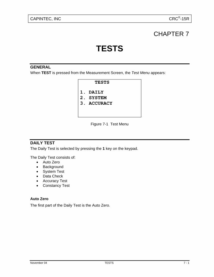
CAPINTEC, INC CRC®-15R
CHAPTER 7
TESTS
GENERAL When TEST is pressed from the Measurement Screen, the Test Menu appears:
TESTS 1. DAILY 2. SYSTEM 3. ACCURACY
Figure 7-1 Test Menu
DAILY TEST The Daily Test is selected by pressing the 1 key on the keypad. The Daily Test consists of:
• Auto Zero • Background • System Test • Data Check • Accuracy Test • Constancy Test
Auto Zero The first part of the Daily Test is the Auto Zero.
November 04 TESTS 7 - 1

CAPINTEC, INC CRC®-15R
AUTO ZERO NO SOURCES Any Key to Continue
Figure 7-2 Auto Zero Instructions
Remove all sources from the vicinity of the Chamber and press any key. You will be told to wait until a measurement is available.
AUTO ZERO PLEASE WAIT
Figure 7-3 Auto Zero Please Wait Screen
The results screen will appear:
AUTO ZERO - 0.05 mV OK ENTER to Accept
Figure 7-4 Auto Zero Results Screen
Press ENTER to accept the result and continue the Daily Test. If the value has drifted since the last measurement, it will be indicated. Check to make sure no sources are in the area. If any sources are found, remove them and repeat the measurement. If the value is out of range, an error message will appear. Check to make sure no sources are in the area. If any sources are found, remove them and repeat the measurement. If no sources were found, consult Capintec’s Authorized Service Center.
7 - 2 TESTS November 04

CAPINTEC, INC CRC®-15R
Background The second part of the Daily Test is Background measurement. Background measurement can also be performed by pressing the BKG key. If Background is performed via the BKG key, you will first be told to remove all sources: You will be told to wait until a measurement is available.
BACKGROUND PLEASE WAIT
Figure 7-5 Background Please Wait Screen
BACKGROUND 0.56 µCi OK ENTER to Accept
Figure 7-6 Background Results Screen
If the background is high but still acceptable (> 27µCi and < 500µCi or > 1MBq and < 20MBq) the word “HIGH” will appear instead of “OK”. Although the value is acceptable, the reason for the high value should be investigated. If any sources are found nearby, repeat the measurement. If the background is above the acceptable range (> 500µCi or > 20MBq), the value will not be shown but the Background Too High Screen will appear:
November 04 TESTS 7 - 3

CAPINTEC, INC CRC®-15R
BACKGROUND TOO HIGH SEE MANUAL Acknowledge by ID:█
Figure 7-7 Background Too High Screen
This background cannot be accepted by the CRC®-15R. If the cause of the high reading (nearby source, contaminated well etc.) cannot be found, consult Capintec’s Authorized Service Center. System Test The third part of the Daily Test is the System Test. The System Test can also be performed by pressing 2 on the keypad when at the Test Menu (Figure 7-1).
SYSTEM TEST PLEASE WAIT
Figure 7-8 System Test Please Wait Screen
When a measurement is available, it is compared with the value entered at the factory and displayed:
SYSTEM TEST 151.2V OK ENTER to Accept
Figure 7-9 System Test Results Screen
If the results are out of range, the message “FAIL SEE MANUAL” appears. If this happens, contact Capintec’s Authorized Service Center.
7 - 4 TESTS November 04

CAPINTEC, INC CRC®-15R
Data Check The next part of the Daily Test is a check of the built-in nuclide data.
DATA CHECK OK Any Key to Continue
Figure 7-10 Data Check Results
If this test ever fails, consult Capintec’s Authorized Service Center. Accuracy Test and Constancy Test
Accuracy and Constancy Test in Daily Test The next part of the Daily Test is the Accuracy Test. You will be stepped through performing the Accuracy Test for all sources, which have been designated as a Daily Source (See CHAPTER 5: SYSTEM INITIALIZATION, SECTION: ENTERING TEST SOURCE DATA). When the source designated as the Constancy Source has been measured, you will be instructed to perform the Constancy Test. In the example below, Co57 is the Daily Source and the Constancy Source.
MEASURE CO57 S/N:123456ABC Any Key to continue
Figure 7-11 Accuracy Test in Daily Test Instruction Screen
Press any key to continue testing. The measurement screen will appear with the calculated activity of the source in the upper right hand corner. The deviation between the measured activity and the calculated activity will be displayed. If the deviation is greater than ±20%, dashes will be shown instead of the deviation – this indicates an error condition (perhaps the wrong source is being measured).
November 04 TESTS 7 - 5

CAPINTEC, INC CRC®-15R
CO57 4.41mCi
4.68 mCi D e v i a t i o n : 6.2% ENTER to Accept
Figure 7-12 Accuracy Test Measurement Screen
Press ENTER to accept the measurement. If the source being measured is not the Constancy Source, the instruction screen for the next Daily Source will appear. If the source being measured is the Constancy Source, the Constancy Test Instruction Screen will appear:
LEAVE SOURCE IN FOR CONSTANCY TEST Any Key to Continue
Figure 7-13 Constancy Test Instruction Screen
When any key (except HOME) is pressed, the Constancy Measurement Screen for the nuclide that is the Constancy Source will appear:
CO57 CONSTANCY TEST
4.68 mCi Cal #: 112
Figure 7-14 Constancy Test Measurement Screen
To perform Constancy Test for other nuclides, press any pre-set nuclide key, user key or specify nuclide via NUCL key.
7 - 6 TESTS November 04

CAPINTEC, INC CRC®-15R
When all Constancy Tests are done, press ENTER to end the test. The Daily Test report will be printed.
Accuracy Test from Menu Accuracy Test can also be performed by pressing 3 on the keypad when at the Test Menu (Figure 7-1). This will allow you to perform the test using any of the Test Sources. The “Accuracy Test Measure?” screen will appear for each Test Source (Co57 is again used as the example):
MEASURE CO57 S/N:123456ABC Y OR N ?
Figure 7-15 Accuracy Test Measure? Screen
Press Y to measure the source. Press N to skip the measurement and proceed to the next Test Source. When all desired sources have been measured, the Accuracy Test Report will be printed.
DIAGNOSTIC TEST When DIAGNOSTICS is selected, the system diagnostic testing will begin. The instrument's memories and the programs are checked (this takes about 1 to 2 minutes) and the results printed and displayed. If any of these tests (RAM, PROM or EEPROM) fail, contact Capintec’s Authorized Service Center. Press UTIL from the Measurement Screen. Press 3 to select DIAGNOSTICS. If a printer is part of the system, but is not ready for printing, you will see the display illustrated in Figure 7-16. If you want a printed report, get the printer ready before doing anything else. Press any key (except HOME) to continue. If the printer is ready, or if the system does not include a printer, this step will be skipped. Nuclear data and other system values will be printed. This printout should be kept for future reference.
November 04 TESTS 7 - 7

CAPINTEC, INC CRC®-15R
DIAGNOSTICS CHECK PRINTER Any Key to Continue
Figure 7-16
Note: The above message “Check Printer” is displayed if the OKI Printer is selected as the
system printer. If the SLIP Printer is selected as the system printer, the Message is “Connect Printer”. If the ROLL Printer is selected as the system printer, no Message is displayed.
Next, you will see the screen illustrated in Figure 7-17. The PROM test requires about 1-1/2 minutes. Be patient.
DIAGNOSTICS RAM: PASS
PROM:
PLEASE WAIT
Figure 7-17
The test results will appear on the display similar to that illustrated in Figure 7-18. The test should always indicate PASS for RAM, PROM‚ and EEPROM. If any of these tests indicate FAIL, copy all of the other data on the display and contact Capintec’s Authorized Service Center. When you have finished viewing the results, press any key to continue.
DIAGNOSTICS RAM: PASS PROM: PASS XXXX XXXX XXXX XXXX XXXX EEPROM: PASS Any Key to Continue
Figure 7-18
7 - 8 TESTS November 04

CAPINTEC, INC CRC®-15R
Diagnostics Printout Examples of the printout are shown on the following pages for the Okidata 320 printer. (The PROM values are just examples).
November 04 TESTS 7 - 9

CAPINTEC, INC CRC®-15R
Figure 7-19 Diagnostics Printout on OKIDATA Printer (page 1 of 4 pages)
7 - 10 TESTS November 04

CAPINTEC, INC CRC®-15R
Figure 7-19 Diagnostics Printout on OKIDATA Printer (page 2 of 4 pages)
November 04 TESTS 7 - 11

CAPINTEC, INC CRC®-15R
Figure 7-19 Diagnostics Printout on OKIDATA Printer (page 3 of 4 pages)
7 - 12 TESTS November 04

CAPINTEC, INC CRC®-15R
Figure 7-19 Diagnostics Printout on OKIDATA Printer (page 4 of 4 pages)
November 04 TESTS 7 - 13


CAPINTEC, INC CRC®-15R
CHAPTER 8
MEASUREMENT PROCEDURES
GENERAL Instructions for measuring a sample are given in this section. The Measurement Screen is shown below.
TC99m 13:55
6.27 mCi Cal #: 080
Figure 8-1 Measurement Screen
MEASUREMENT PROCEDURES Note: In order to obtain a correct reading for a Vial or Syringe, the supplied liner and dipper
must be used to achieve the correct geometry. If the source is contained in a different type of container, then contact Capintec, Inc. for further assistance.
General Activity Measurement Procedure To measure the activity of a sample:
Insert sample into the Chamber. Specify nuclide.
To print a record of the measurement:
Press ENTER. To find out what the activity will be at a different time:
Press TIME. Specifying Nuclide A nuclide may be specified via one of the pre-set nuclide keys, one of the user keys or via the NUCL key.
November 04 MEASUREMENT PROCEDURES 8 - 1

CAPINTEC, INC CRC®-15R
Pre-Set Nuclide Key: Press one of the 9 pre-set Nuclide Keys. Co57 Ga67 Tc99m F18 In111 I123 I131 Xe133 Tl201
User Key: Press one of the 4 User Assigned Nuclide Keys. U1 U2 U3 U4
Note: Before using one of these keys, a nuclide must be assigned to the key. (See:
CHAPTER 5: SYSTEM INITIALIZATION, SECTION: USER KEY ASSIGNMENT)
NUCL Key:
Press NUCL. “SPECIFY NUCLIDE” is displayed. Input the nuclide name via the number/letter keys (only numbers will appear). Press ENTER when done. The entire name does not have to be input. If the nuclide is not uniquely specified, a list of possibilities will appear. (If there are more than 10 possibilities, “SPECIFY FURTHER” will appear.) Input the number corresponding to the desired nuclide and press ENTER. If NUCL was accidentally pressed, press ENTER without any input.
Entering Calibration Number A measurement may also be made by entering a calibration number instead of selecting a nuclide from memory. Press CAL#. “ENTER CALIBRATION #” is displayed. Input the desired calibration number and press ENTER. A calibration number may include a multiplication sign (* on the keyboard, displayed as X) or a division sign. However, the chamber is always direct reading and the multiplication or division sign is only used to be consistent with existing calibration numbers. If CAL# was accidentally pressed, press HOME to return to Figure 8-1.
8 - 2 MEASUREMENT PROCEDURES November 04

CAPINTEC, INC CRC®-15R
Selecting Range The CRC®-15R is auto ranging over 3 ranges. However, the ranges can be cycled through manually by using the UP ( ) and DOWN ( ) ARROW keys. When the unit is first powered on, the display will be in the high activity range (.xx mCi). To display greater accuracy with the medium activity range (x. µCi), press the DOWN ARROW ( ). For the greatest accuracy, select the low activity range (x.xx µCi) by pressing the DOWN ARROW ( ) again. Pressing the DOWN ARROW ( ) a third time will keep the unit in the low activity range (x.xx µCi) but with a longer averaging time. Pressing the UP ARROW ( ) will reverse the process. When HOME is pressed, the display reverts to the power up range (high activity range).
ACTIVITY AT A DIFFERENT TIME It is often desirable to know the activity of the sample at another time (usually in the future). When another date / time is chosen, the activity at that date and time will be displayed (and printed) along with the measured activity. The feature is only available when a nuclide is specified because the half-life of the nuclide must be known. Press TIME. The calibration number is erased and the current time and date appear in the order: hour, minute, Day, Month, Year. The hour is highlighted.
TC99m 17:29
6.27 mCi h m D M Y 12 43 19 03 04
Figure 8-2 Time / Date Input Screen
Use the ARROW keys to highlight the field (hour, min, Day, Month, Year) that you want to change, then use the numeric keypad to change the value of that field. Press ENTER when the desired time and date is displayed.
November 04 MEASUREMENT PROCEDURES 8 - 3
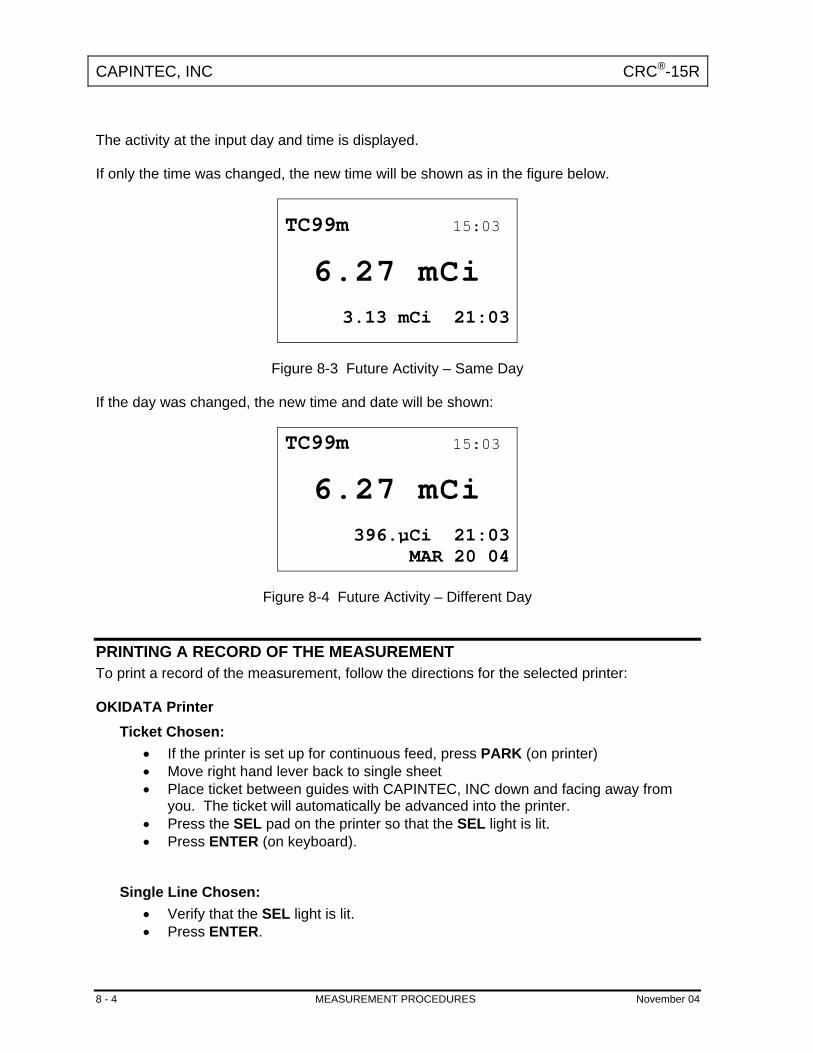
CAPINTEC, INC CRC®-15R
The activity at the input day and time is displayed. If only the time was changed, the new time will be shown as in the figure below.
TC99m 15:03
6.27 mCi
3.13 mCi 21:03
Figure 8-3 Future Activity – Same Day
If the day was changed, the new time and date will be shown:
TC99m 15:03
6.27 mCi
396.µCi 21:03MAR 20 04
Figure 8-4 Future Activity – Different Day
PRINTING A RECORD OF THE MEASUREMENT To print a record of the measurement, follow the directions for the selected printer: OKIDATA Printer
Ticket Chosen: • If the printer is set up for continuous feed, press PARK (on printer) • Move right hand lever back to single sheet • Place ticket between guides with CAPINTEC, INC down and facing away from
you. The ticket will automatically be advanced into the printer. • Press the SEL pad on the printer so that the SEL light is lit. • Press ENTER (on keyboard).
Single Line Chosen:
• Verify that the SEL light is lit. • Press ENTER.
8 - 4 MEASUREMENT PROCEDURES November 04

CAPINTEC, INC CRC®-15R
Roll Printer
• Press ENTER.
Slip Printer
• If the RELEASE light (on printer) is not lit, press RELEASE (on printer). • Place Ticket in printer, face up. • Slide the ticket under the mechanism until the PAPER OUT light is off. • Press ENTER (on keyboard).
MOLY ASSAY The CRC®-15R steps the user through a Moly Assay procedure. The assay may be performed in the CAPMAC or the CANISTER. If one method (CAPMAC or CANISTER) is to be used all the time, choose the method in Utilities (See: CHAPTER 5: SYSTEM INITIALIZATION, SECTION: MOLY ASSAY METHOD). To perform a Moly Assay, press Mo Assay key while in the Measurement Screen. If the assay method has not been uniquely specified, you must choose the method.
SELECT 1. CAPMAC for Mallinckrodt Gen 2. CAPMAC for Bristol Myers Gen 3.Capintec Canister
Figure 8-5 Moly Assay Method Selection Screen
Select the method to be used for the current test only. If only CAPMAC or only CANISTER has been chosen in utilities, this screen will be skipped. Mo99 Background Measuring the background for Mo99 is optional. This background will only be used for the current assay. If it is skipped, the background previously measured by pressing BKG or during the Daily Test will be used. The following examples are for CAPMAC. CANISTER will be exactly the same except that the screens will prompt for measurements in the CANISTER.
November 04 MEASUREMENT PROCEDURES 8 - 5

CAPINTEC, INC CRC®-15R
MO99 BKG EMPTY CAPMAC Press N(6) to Skip Other Key to Proceed
Figure 8-6 Moly Assay Background Choice Screen
Press N if you don't want to measure background with the CAPMAC or CANISTER. You will go directly to Mo99 Assay. Press any other key (except HOME) to begin Mo background measurement (Moly Assay Instruction Screen). Measuring Mo99 background is very similar to measuring background via BKG key or Daily Test.
MO99 BKG PLEASE WAIT
Figure 8-7 Moly Assay Background Wait Screen
When a measurement is ready:
MO99 BKG
.27µCi PLEASE WAIT
Figure 8-8 Moly Assay Background Measurement Ready Screen
When enough measurements are made, you may accept the measurement and continue:
8 - 6 MEASUREMENT PROCEDURES November 04

CAPINTEC, INC CRC®-15R
MO99 BKG
.27µCi OK ENTER to Accept
Figure 8-9 Moly Assay Background Measurement Accept Screen
Press ENTER to accept measurement and continue to Mo99 Assay. Note: The activity will be tested to see if it's too high the same way that Background is
tested. Mo99 Assay You will now be instructed to measure the eluate in the CAPMAC or CANISTER.
MO99 ASSAY ELUATE IN CAPMAC Any Key to Continue
Figure 8-10 Moly Assay Instruction Screen
Press any key (except HOME) to begin the measurement. Since this is also a measurement of a very low activity, the screens are similar to background:
MO99 ASSAY PLEASE WAIT
Figure 8-11 Moly Assay Wait Screen
November 04 MEASUREMENT PROCEDURES 8 - 7

CAPINTEC, INC CRC®-15R
When a measurement is ready:
MO99 ASSAY
.33µCi PLEASE WAIT
Figure 8-12 Moly Assay Ready Screen
When enough measurements are made, then you may accept the measurement and continue:
MO99 ASSAY
.47µCi ENTER to Accept
Figure 8-13 Moly Assay Accept Screen
Press ENTER to accept measurement and continue to Tc99m Assay. Note: The activity will be tested to see if it's too high the same way that Mo99 Background
is tested. Tc99m Assay The Tc99m Assay is performed next:
TC99m ASSAY
1.127 Ci ENTER to Accept
Figure 8-14 Tc99m Measurement
8 - 8 MEASUREMENT PROCEDURES November 04

CAPINTEC, INC CRC®-15R
Press ENTER to accept the measurement. Note: An error message (ACTIVITY TOO LOW – Any Key to Continue) will appear if the
Tc99m activity is too low (below 1 mCi). Moly Assay Results The Mo99/Tc99m ratio is calculated and displayed. The ratio is compared to the allowable value (which can be changed in Utilities) and the time when the ratio will exceed this limit is calculated. If the calculated time limit is less than 12 hours, a usage message is displayed depending upon the useable time for the elution. An example of such a case is given below:
MO99/TC99m: .058 µCi/mCi DO NOT USE AFTER 9 HOURS Acknowledge by ID:
Figure 8-15 Mo99/Tc99m Exceeding Limit Screen
Input your ID number and press ENTER to acknowledge the usage message, erase it. The next screen requests the user to enter the volume of the eluate in ml. This is the screen that will appear if the ratio is within limits and is useable for more than 12 hours.
MO99/TC99m: .058 µCi/mCi VOLUME? ml █
Figure 8-16 Mo99/Tc99m with Volume Entry Screen
Enter the volume of the elution and press ENTER. The concentration of the elution is calculated and displayed.
November 04 MEASUREMENT PROCEDURES 8 - 9

CAPINTEC, INC CRC®-15R
TC99m 1.127 Ci 112.7 mCi/ml Any Key to Continue
Figure 8-17 Elution Concentration Screen
Press any key (except HOME) to print a ticket with the details of the assay. You will then be asked if you want to print again. If Y is pressed, another ticket is printed. If N is pressed, you will be returned to the Measurement Screen.
8 - 10 MEASUREMENT PROCEDURES November 04
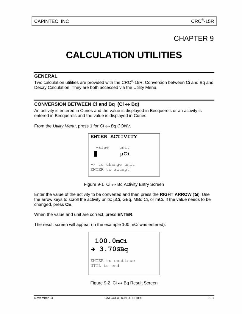
CAPINTEC, INC CRC®-15R
CHAPTER 9
CALCULATION UTILITIES
GENERAL Two calculation utilities are provided with the CRC®-15R: Conversion between Ci and Bq and Decay Calculation. They are both accessed via the Utility Menu.
CONVERSION BETWEEN Ci and Bq (Ci ↔ Bq) An activity is entered in Curies and the value is displayed in Becquerels or an activity is entered in Becquerels and the value is displayed in Curies. From the Utility Menu, press 1 for Ci ↔ Bq CONV.
ENTER ACTIVITY value unit
█ µCi -> to change unit ENTER to accept
Figure 9-1 Ci ↔ Bq Activity Entry Screen
Enter the value of the activity to be converted and then press the RIGHT ARROW ( ). Use the arrow keys to scroll the activity units: µCi, GBq, MBq Ci, or mCi. If the value needs to be changed, press CE. When the value and unit are correct, press ENTER. The result screen will appear (in the example 100 mCi was entered):
100.0mCi 3.70GBq
ENTER to continue UTIL to end
Figure 9-2 Ci ↔ Bq Result Screen
November 04 CALCULATION UTILITIES 9 - 1
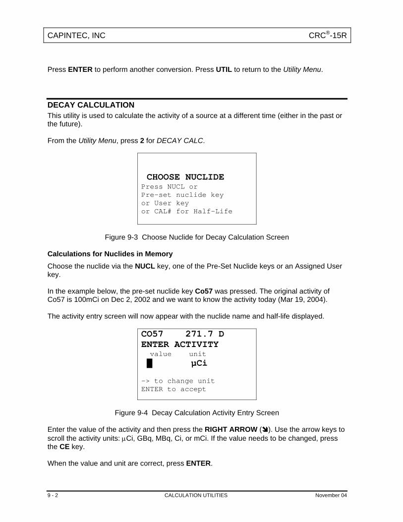
CAPINTEC, INC CRC®-15R
Press ENTER to perform another conversion. Press UTIL to return to the Utility Menu.
DECAY CALCULATION This utility is used to calculate the activity of a source at a different time (either in the past or the future). From the Utility Menu, press 2 for DECAY CALC.
CHOOSE NUCLIDE Press NUCL or Pre-set nuclide key or User key or CAL# for Half-Life
Figure 9-3 Choose Nuclide for Decay Calculation Screen
Calculations for Nuclides in Memory Choose the nuclide via the NUCL key, one of the Pre-Set Nuclide keys or an Assigned User key. In the example below, the pre-set nuclide key Co57 was pressed. The original activity of Co57 is 100mCi on Dec 2, 2002 and we want to know the activity today (Mar 19, 2004). The activity entry screen will now appear with the nuclide name and half-life displayed.
CO57 271.7 D ENTER ACTIVITY value unit █ µCi -> to change unit ENTER to accept
Figure 9-4 Decay Calculation Activity Entry Screen
Enter the value of the activity and then press the RIGHT ARROW ( ). Use the arrow keys to scroll the activity units: µCi, GBq, MBq, Ci, or mCi. If the value needs to be changed, press the CE key. When the value and unit are correct, press ENTER.
9 - 2 CALCULATION UTILITIES November 04

CAPINTEC, INC CRC®-15R
CO57 271.7 D FROM: h m D M Y 14 23 02 12 02
Figure 9-5 Decay Calculation Activity Starting Time/Date Screen
The current time/date will appear. If the starting time/date is “now”, press ENTER. Otherwise, use the arrow keys to change the date and/or time and press ENTER.
CO57 271.7 D TO: h m D M Y 14 23 19 03 04
Figure 9-6 Decay Calculation Activity Ending Time/Date Screen
The current time/date will appear. If the ending time/date is “now”, press ENTER. Otherwise, use the arrow keys to change the date and/or time and press ENTER. The results screen will appear:
CO57 271.7 D 100.0mCi 14:23 DEC 02 2002 29.9mCi 14:23 MAR 19 2004
Figure 9-7 Decay Calculation Result Screen
Press any key when finished viewing the results. You will be returned to the Choose Nuclide for Decay Calculation Screen. To exit Decay Calculation, press UTIL to return to the Utility Menu or HOME to return to the Measurement Screen.
November 04 CALCULATION UTILITIES 9 - 3
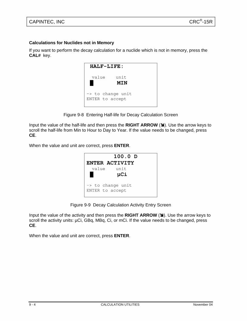
CAPINTEC, INC CRC®-15R
Calculations for Nuclides not in Memory If you want to perform the decay calculation for a nuclide which is not in memory, press the CAL# key.
HALF-LIFE: value unit █ MIN -> to change unit ENTER to accept
Figure 9-8 Entering Half-life for Decay Calculation Screen
Input the value of the half-life and then press the RIGHT ARROW ( ). Use the arrow keys to scroll the half-life from Min to Hour to Day to Year. If the value needs to be changed, press CE. When the value and unit are correct, press ENTER.
100.0 D ENTER ACTIVITY value unit █ µCi -> to change unit ENTER to accept
Figure 9-9 Decay Calculation Activity Entry Screen
Input the value of the activity and then press the RIGHT ARROW ( ). Use the arrow keys to scroll the activity units: µCi, GBq, MBq, Ci, or mCi. If the value needs to be changed, press CE. When the value and unit are correct, press ENTER.
9 - 4 CALCULATION UTILITIES November 04

CAPINTEC, INC CRC®-15R
100.0 D FROM: h m D M Y 14 46 02 12 02
Figure 9-10 Decay Calculation Activity Starting Time / Date Screen
The current time/date will appear. If the starting time/date is “now”, press ENTER. Otherwise, use the arrow keys to change the date and/or time and press ENTER.
100.0 D TO: h m D M Y 14 47 19 03 04
Figure 9-11 Decay Calculation Activity Ending Time/Date Screen
The current time/date will appear. If the ending time/date is “now”, press ENTER. Otherwise, use the arrow keys to change the date and/or time and press ENTER. The results screen will appear:
100.0 D 100.0mCi 14:46 DEC 02 2002 3.77mCi 14:47 MAR 19 2004
Figure 9-12 Decay Calculation Result Screen
Press any key when finished viewing the results. You will be returned to the Choose Nuclide for Decay Calculation Screen. To exit Decay Calculation, press UTIL to return to the Utility Menu or HOME to return to the Measurement Screen.
November 04 CALCULATION UTILITIES 9 - 5

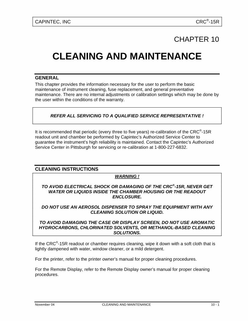
CAPINTEC, INC CRC®-15R
CHAPTER 10
CLEANING AND MAINTENANCE
GENERAL This chapter provides the information necessary for the user to perform the basic maintenance of instrument cleaning, fuse replacement, and general preventative maintenance. There are no internal adjustments or calibration settings which may be done by the user within the conditions of the warranty.
REFER ALL SERVICING TO A QUALIFIED SERVICE REPRESENTATIVE ! It is recommended that periodic (every three to five years) re-calibration of the CRC®-15R readout unit and chamber be performed by Capintec’s Authorized Service Center to guarantee the instrument’s high reliability is maintained. Contact the Capintec’s Authorized Service Center in Pittsburgh for servicing or re-calibration at 1-800-227-6832.
CLEANING INSTRUCTIONS WARNING !
TO AVOID ELECTRICAL SHOCK OR DAMAGING OF THE CRC®-15R, NEVER GET
WATER OR LIQUIDS INSIDE THE CHAMBER HOUSING OR THE READOUT ENCLOSURE.
DO NOT USE AN AEROSOL DISPENSER TO SPRAY THE EQUIPMENT WITH ANY
CLEANING SOLUTION OR LIQUID.
TO AVOID DAMAGING THE CASE OR DISPLAY SCREEN, DO NOT USE AROMATIC HYDROCARBONS, CHLORINATED SOLVENTS, OR METHANOL-BASED CLEANING
SOLUTIONS. If the CRC®-15R readout or chamber requires cleaning, wipe it down with a soft cloth that is lightly dampened with water, window cleaner, or a mild detergent. For the printer, refer to the printer owner’s manual for proper cleaning procedures. For the Remote Display, refer to the Remote Display owner’s manual for proper cleaning procedures.
November 04 CLEANING AND MAINTENANCE 10 - 1

CAPINTEC, INC CRC®-15R
PREVENTATIVE MAINTENANCE The Quality Assurance Tests described in CHAPTER 6: ACCEPTANCE & QUALITY ASSURANCE TESTS, should be performed periodically as stated. Tests must be performed in an environment where the temperature is stable within a range of +50°F to +85°F (+10°C to +30°C) and the maximum relative humidity is 90% non-condensing. The unit should be powered-up for at least one-half hour prior to performing any measurements. No other precautions need to be observed.
CAUTION If these environmental requirements are not followed,
the instrument may display erroneous readings. If the unit fails to pass Autocalibration Test or any other test, the user should not attempt to perform any adjustments to the system. In this event, please contact Capintec for further assistance. The Quality Assurance tests should be immediately performed if:
• The equipment has been subjected to extreme physical stress, • Liquids enter the readout unit, and/or chamber, or • Any cable shows signs of damage
SERVICING The system is covered by a one year limited warranty, under normal conditions of use. Other than the Readout Unit fuses (see Fuse Servicing in this chapter), there are no user serviceable parts contained in the system. Every five years, the system should be returned to Capintec’s Authorized Service Center for a complete verification. CAPINTEC, Inc. 540 Alpha Drive Pittsburgh, PA 15238 Phone (412) 963-1988, 1-800-227-6832 Fax (412) 963-0610
DISPOSAL The following items should be taken into consideration before disposing. The unit contains two types of hazardous items:
1. Lead – the shielding around the chamber. 2. Lithium Battery – contained on the HPC/CPU printed circuit board inside of the
readout unit. These items should be disposed of in accordance with local and national regulations.
10 - 2 CLEANING AND MAINTENANCE November 04
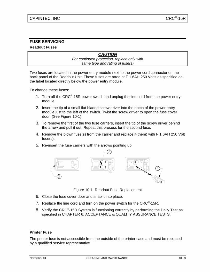
CAPINTEC, INC CRC®-15R
FUSE SERVICING Readout Fuses
CAUTION For continued protection, replace only with
same type and rating of fuse(s) Two fuses are located in the power entry module next to the power cord connector on the back panel of the Readout Unit. These fuses are rated at F 1.6AH 250 Volts as specified on the label located directly below the power entry module. To change these fuses:
1. Turn off the CRC®-15R power switch and unplug the line cord from the power entry module.
2. Insert the tip of a small flat bladed screw driver into the notch of the power entry module just to the left of the switch. Twist the screw driver to open the fuse cover door. (See Figure 10-1).
3. To remove the first of the two fuse carriers, insert the tip of the screw driver behind the arrow and pull it out. Repeat this process for the second fuse.
4. Remove the blown fuse(s) from the carrier and replace it(them) with F 1.6AH 250 Volt fuse(s).
5. Re-insert the fuse carriers with the arrows pointing up.
Figure 10-1 Readout Fuse Replacement 6. Close the fuse cover door and snap it into place. 7. Replace the line cord and turn on the power switch for the CRC®-15R. 8. Verify the CRC®-15R System is functioning correctly by performing the Daily Test as
specified in CHAPTER 6: ACCEPTANCE & QUALITY ASSURANCE TESTS. Printer Fuse The printer fuse is not accessible from the outside of the printer case and must be replaced by a qualified service representative.
November 04 CLEANING AND MAINTENANCE 10 - 3

CAPINTEC, INC CRC®-15R
TROUBLESHOOTING Some problems may be very easy to diagnose and correct in the field with little or no equipment. If a problem should occur, check here before you call for service. You may be able to save a considerable amount of time and money. Nothing appears on the display.
• Make sure calibrator is plugged into a live outlet and is turned on. • Check fuse and replace if necessary. See: FUSE SERVICING.
Nothing happens when any key is pressed.
• One of the keys may be stuck. Try wiggling each key. • A brief power line disruption may have caused the program to “lose its place”. Try
turning the power off and then on again.
Buzzer buzzes continuously.
• A brief power line disruption may have caused the program to “lose its place”. Try turning the power off and then on again. If the buzzing continues, turn the power off and consult the factory. DO NOT leave the unit buzzing longer than necessary.
High background indication.
• Chamber Well, liner, or dipper may have become contaminated. See: CHAPTER 6: ACCEPTANCE & QUALITY ASSURANCE TESTS, SECTION: CONTAMINATION TEST.
• Background may actually be high. Check by removing the dipper and placing a lead sheet over the top of the well.
Zero activity is indicated with a source in the well.
• System may not be in lowest range. Try pressing SPC.
Readings appear overly noisy for low activities.
• System may not be in long averaging period. Try pressing SPC twice. • Make sure that the chamber is on a solid surface and is not subject to vibration.
Indication of significant negative activity.
• Background level may have changed. Re-do the Background Adjust. See: CHAPTER 7: TESTS, SECTION: BACKGROUND.
Printer prints junk or prints with incorrect spacing.
• Make sure that the Printer Menu Setup is correct. See: CHAPTER 5: SYSTEM INITIALIZATION, SECTION: PRINTING.
10 - 4 CLEANING AND MAINTENANCE November 04

CAPINTEC, INC CRC®-15R
Print head hangs up when printing tickets.
• Lever on left side of print head must be set to position 2.
Printer will not respond.
• Make sure printer is plugged into a live outlet, turned on, and “selected”. • Make sure that either paper or a ticket is in the paper path. • Run the Diagnostic Test and make sure that the system expects to have a printer.
If not, add it to the Factory Set-up data. • Make sure that the Printer Menu Setup is correct See: CHAPTER 5: SYSTEM
INITIALIZATION, SECTION: PRINTING.
ACCESSORIES AND REPLACEMENT PARTS The following accessories and replacement parts are available from Capintec. Call Capintec’s Authorized Service Center at 1-800-227-6832 for answers to your questions or to place an order.
• CAPMAC Moly Assay Kit (specify generator)....................................CALL • Dose Calibrator Reference Sources..................................................CALL • Shielded products for PET.................................................................CALL • Standard Moly Assay Kit ...............................................................5130-0006 • Calicheck Linearity Test Kit ...........................................................5120-2144 • Ionization Chamber Well Inserts (liners)........................................7300-2004 • Plastic Sample Holders (dippers) ..................................................7300-2005 • Environmental Shield.....................................................................7300-2450 • Flush Mount Mounting Flange .......................................................7310-2307 • Shielded Platform with 2mm shielded glass ..................................5150-3010 • Shielded Platform with 4mm shielded glass ..................................5150-3011 • Dosilift™ remote lowering/raising of syringes or vials ...................5120-2175 • Remote Display .............................................................................5130-2082 • RS-232 Port ...................................................................................5130-0151 • Keyboard Membrane .....................................................................7800-2164 • Okidata 320 Ticket and Report Printer ..........................................5110-1150 • Epson Roll Printer..........................................................................5430-0058 • Epson Ticket Printer ......................................................................5430-0100 • Printer Ribbons..................................................................................CALL • Multi-part Tickets, Paper, etc. ............................................................CALL • Additional copies of Owner’s Manual ............................................9250-0038
Note: Circuit diagrams, component parts lists, descriptions and calibration instructions are
available to appropriately qualified personnel.
November 04 CLEANING AND MAINTENANCE 10 - 5

CAPINTEC, INC CRC®-15R
SHIPPING If for any reason the CRC®-15R must be returned to Capintec, the shipping carton must contain the following or equivalent labeling as shown in figures 10-2 and 10-3. Label stipulating the maximum environmental conditions for safe storage and shipment.
Figure 10-2
Figure 10-3 In order to ship this product, all appropriate Department of Transportation (DOT) and, if shipped by air, the International Aviation and Transportation Administration (IATA) requirements for the shipment of the pressurized (12 Atmosphere) Ionization Chamber Detector must be met.
10 - 6 CLEANING AND MAINTENANCE November 04
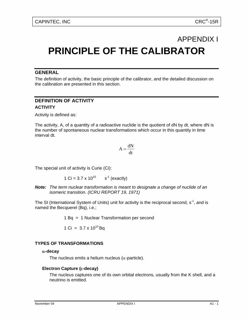
CAPINTEC, INC CRC®-15R
APPENDIX I
PRINCIPLE OF THE CALIBRATOR
GENERAL The definition of activity, the basic principle of the calibrator, and the detailed discussion on the calibration are presented in this section.
DEFINITION OF ACTIVITY ACTIVITY Activity is defined as: The activity, A, of a quantity of a radioactive nuclide is the quotient of dN by dt, where dN is the number of spontaneous nuclear transformations which occur in this quantity in time interval dt.
dtdNA =
The special unit of activity is Curie (Ci): 1 Ci = 3.7 x 10¹⁰ s-1 (exactly) Note: The term nuclear transformation is meant to designate a change of nuclide of an
isomeric transition. (ICRU REPORT 19, 1971) The SI (International System of Units) unit for activity is the reciprocal second, s-1, and is named the Becquerel (Bq), i.e.; 1 Bq = 1 Nuclear Transformation per second 1 Ci = 3.7 x 10¹⁰ Bq TYPES OF TRANSFORMATIONS
α-decay The nucleus emits a helium nucleus (α-particle).
Electron Capture (ε-decay) The nucleus captures one of its own orbital electrons, usually from the K shell, and a neutrino is emitted.
November 04 APPENDIX I A1 - 1

CAPINTEC, INC CRC®-15R
β- Decay The nucleus emits an electron (β- particle), and a neutrino.
β+ decay The nucleus emits a positron (β+ particle) and a neutrino.
Nuclear Transition A photon (electromagnetic radiation, γ-decay), electron (Internal Conversion Electron Emission, CE or electron-positron pair (Internal-pair emission, e±) is emitted by a nucleus in a transition from a higher to lower energy state. No nuclear transformation occurs if there is no change in the atomic number nor the mass number. The de-excitation of a nucleus in its unstable state (metastable state) is, however, included in the definition of activity.
MEASUREMENT OF ACTIVITY A Nuclear Transformation is always associated with one or more of the following types of radiation:
α β+, β- and ν Photons
We can, therefore, measure activity by detecting one or more of the above radiations. α-PARTICLE RADIATION
The most energetic α-particle emitted by a radionuclide has an energy of less than 10 MeV, which corresponds to a range of about 10 mg/cm2 (8 cm in air). Because of its short range, an α-particle from a radionuclide cannot penetrate to the ionization chamber's sensitive volume and therefore, cannot be detected. All α-decays, however, are accompanied by photon radiation as the daughter nucleus decays to its ground state. The activity of a nuclide which decays through a radiation can therefore, be measured by detecting the associated photon radiation. β+ RADIATION
β+ particle (positron) emitted from a nucleus comes to rest in the media by losing its kinetic energy mainly by direct ionization processes and then annihilates with an electron to produce two photons of 511 keV each. These photons are easily detected by the ionization chamber. De-excitation photons are also associated with β+ decay. β- RADIATION The ejected electron loses kinetic energy in matter mainly by direct ionization.
A1 - 2 APPENDIX I November 04

CAPINTEC, INC CRC®-15R
The range of most emitted β's is very short. It should be noted that in β+ and β-emission, the emitted electron or positron has a continuous energy spectrum, which ranges from Emax to zero, where Emax is the maximum transition energy. β-rays (with the exception of a small portion of very high energy βs) will be stopped in the sample, in the chamber liner, and in the chamber wall. As the electron decelerates, it also produces continuous low energy photon emission called Bremsstrahlung (stopping or braking radiation). Many radionuclides that decay by β emission also emit de-excitation photons (x-rays, γ-rays), which can be detected by the ionization chamber. ELECTRON CAPTURE The actual electron capture process cannot be detected since the electron is not emitted but is captured by the nucleus. The capture of the orbital electron, however, leaves a vacancy in the atomic orbital shell, resulting in x-rays as the atom de-excites. The energy of k x-ray is approximately
100
2ZEk ≈ [keV]
where Z is the atomic number of the daughter nucleus. γ-rays are also often given off as the daughter nucleus de-excites. PHOTON RADIATION Photon radiation is associated with most nuclear transformations. A high energy photon interacts with matter very weakly. Photon intensity is therefore, not altered substantially by the surrounding media, i.e., measurement of activity can be accomplished with a minimum of disturbance from the sample configuration. As can be seen from the above, in all cases we are detecting photons. We will therefore, discuss photons and their interactions with matter in detail.
PHOTONS Photon is the general term for a quantum of radiation. Photons are classified according to their method of production. γ-Rays Photons resulting from nuclear transitions, nuclear reaction or annihilation of particles (e.g., electron-positron annihilation) are called Gamma-rays (γ-rays). Radioisotope sources
November 04 APPENDIX I A1 - 3

CAPINTEC, INC CRC®-15R
(radionuclides) are the most common means of γ-ray production. Radioisotope γ-sources emit photons of one or more discrete energies. X-Rays X-rays are associated with the deceleration of electrons or with orbital electron transitions in atoms. The radiation from a γ-source is often accompanied by characteristic x-rays from transitions of the orbital electrons in the daughter atom. Bremsstrahlung When very fast electrons are brought to rest in a medium (or pass through media) a continuous low energy photon spectrum occurs. This is called Bremsstrahlung ("stopping or braking radiation"). The intensity and the energy spectrum of Bremsstrahlung are highly dependent upon the source configuration and media surrounding the sample. (See Appendix of this manual for more detailed discussion on Bremsstrahlung.) In this manual, the term photon will be used when the method of production of the radiation has no bearing on the discussion. INTERACTIONS OF PHOTONS WITH MATTER There are three mechanisms by which photons can interact with matter and, thus, deposit their energy. These mechanisms are: Photoelectric effect, Compton effect, and, pair production. The energy of the photon determines which process (or processes) are possible.
Photoelectric Effect The photoelectric effect is an interaction between a photon and an electron which is bound to an atom. In the photoelectric process, the photon is absorbed by the atom and a bound electron is ejected. The kinetic energy of the ejected electron is equal to the photon energy minus the binding energy of the electron. The binding energy of an electron is the energy which must be supplied in order to remove the electron from the atom. In nuclear medicine, we are interested in photon energies of 20 keV or greater. At these energies, all the electrons in the materials used for the chambers are able to participate in the photoelectric process. The photoelectric effect is the most important process at low energies. However, for photon energies much greater than electron binding energies, the processes described below become more important and the number of photoelectric interactions occurring becomes small. At a given energy, the number of photoelectric interactions per unit mass varies as the 4th power of the atomic number and is inversely proportional to the atomic weight of the medium (Z4/A).
A1 - 4 APPENDIX I November 04

CAPINTEC, INC CRC®-15R
Compton Effect The Compton Effect is a collision between a photon and an electron which can be considered unbound. An electron can be considered to be unbound (or "free") if the energy of the incident photon is much greater than the binding energy of the electron. The kinetic energy of the scattered electron is not constant, but is a function of the angle through which it is scattered. The scattered photon must interact again in order to impart all of its energy to the medium. The Compton effect is the dominant process for photon energies from 100 keV to about 10 MeV in the region of the atomic numbers for detector materials. At 100 keV, the maximum kinetic energy of the scattered electron is about 30 percent of that of the incident photon; at 1 MeV, it is about 80 per cent; and at 10 MeV, it is about 98 percent. The number of Compton interactions per unit mass varies directly as the atomic number and inversely as the atomic weight of the medium (Z/A).
Pair Production The process of pair production is difficult to comprehend because it is strictly a relativistic quantum mechanical effect. What is observed to take place is that in the presence of the electric field of a nucleus, the incident photon disappears and an electron and a positron appear. (A positron is a particle with the same properties as an electron, except that it has a positive charge.) In order to produce an electron-positron pair, the incident photon must have an energy of at least twice the mass of an electron, i.e., 1.022 MeV. This process dominates for very high energies, that is, above about 10 MeV. The number of pair production interactions per unit mass is proportional to the square of the atomic number and inversely proportional to the atomic weight of the medium (Z2/A).
IONIZATION CHAMBER MEASURING PROCESS An ionization chamber consists of two or more electrodes. The electrodes confine a volume of gas and collect the charge (ions) produced by radiation within the volume. Thus, ionization chambers can be used to measure radiation fields if the relationship between the radiation field and the charge produced is known. The radiation enters the chamber through the chamber wall and interacts with the gas in the chamber or with the chamber wall. It must be pointed out that photons cannot produce ionization directly, but must first interact with the chamber material (gas and wall) producing electrons. That is, through a series of interactions, the photon transfers its energy to one or more electrons. The electron is slowed down through collisions with the chamber gas (argon). The collisions knock electrons off the molecules producing positive ions (this is the ionization process). The collection voltage across the chamber sets up an electric field. The positive ions will drift towards the negative electrode and the electron (and negative ions if they are formed) will drift towards the positive electrode, thus producing a current. The electronic circuitry then measures either the current or the total charge produced during the period of interest.
November 04 APPENDIX I A1 - 5

CAPINTEC, INC CRC®-15R
The number of ions produced in the chamber is directly related to the energy deposited in the chamber by the radiation.
DETERMINING CALIBRATION SETTING NUMBERS A method of determining a calibration setting number is described in this section.1 RESPONSE and Sensitivity It is very convenient to express the response of the detector to a radioisotope, A, relative to that of a standard reference material, e.g. Co60.
⎟⎟⎠
⎞⎜⎜⎝
⎛
⎟⎟⎠
⎞⎜⎜⎝
⎛
≡
Co60 SRM ofActivity CertifiedCo60 SRM todueOutput Detector
A Sample ofActivity A Sample todueOutput Detector
R A (1)
The sensitivity of the detector for a photon of energy Ei is defined as:
60-Co of Curie one todueOutput Dtector
E of Photons 103.7 todueOutput Detector i10
i×
≡S (2)
The detector response and the sensitivity have the following relation: (3) ∑≡
iii SIiR
Where Ii is the intensity of the photon whose energy is Ei. The procedure is to measure the response of the detector to all the available primary standard samples and to establish the sensitivity of the detector as a function of photon energy so as to satisfy equation (3) for all standards. Once the sensitivity curve has been determined, the response of the detector to any radioisotope may be calculated using equation (3), provided that the decay data are known. The sensitivity curve for a CRC®-ionization chamber is given in Figure A1-1. The figure depicts the sensitivity of the ionization chamber as a function of photon energy up to 1.9 MeV. Above a photon energy of 200 keV, the ionization in the chamber is mainly due to electrons resulting from Compton scattering of photons by the filling gas (argon) and the chamber walls (aluminum).
1 See Suzuki, A., Suzuki M.N., and Weis A.M.: Analysis of a Radioisotope Calibrator; Journal of Nuclear Medicine Technology Dec. 1976 for more detailed discussions.
A1 - 6 APPENDIX I November 04

CAPINTEC, INC CRC®-15R
The peak in the low-energy region of the sensitivity curve is due to the rapid increase in photoelectric effect as photon energy decreases and to the attenuation of low energy photons by the sample holder, the chamber liner and the chamber walls, as well as the absorption of photons in the sample material and its container. Although a significant fraction of photons with energies below 50 keV are stopped in the chamber wall, some photons could enter the sensitive volume of the chamber and could, therefore, contribute to the activity measurement. All photons with energies below about 13 keV are stopped before they reach the sensitive volume of the chamber and, therefore, these photons do not contribute to the activity measurement. Calibration Setting Numbers The relationship between the response of the detector and the gain setting (relative to that for Co-60, in order for the instrument to give a direct reading of the activity) is given by:
AR
1G A ≡ (4)
The calibration setting number is linearly related to the chamber response. All the calibrators are calibrated with certified Cobalt-60 and Cobalt-57 standard source. A calibration setting number of 990 was assigned to Co60 and 112 was chosen for Co57. The calibration setting number of CRC® Calibrator for radioisotope A, NA, is given by:
( )( )
( )( )5760
576060
5760
5760AA -1R N
CoCo
CoCoCo
CoCo
CoCo
RRNN
NNNRR
−−
∗⎟⎟⎠
⎞⎜⎜⎝
⎛⎟⎟⎠
⎞⎜⎜⎝
⎛∗
−−
−= (5)
Entering numerical values:
(6)
( )
N 990 N 112R 1.000 R 0.189 2%one obtains: N 1076 R 0.080
Co60 Co57
Co60 Co57
A A
= == = ±
= − The accuracy of the sensitivity curve and the calibration number determination was tested by calculating calibration numbers for all the radioisotope standards used for the studies of the sensitivity. The agreement between the calculated and the observed responses were all within ±3%. The accuracy of the chamber response calculation for a particular radioisotope, hence the accuracy which can be attained by using a calculated Calibration Setting Number depends not only on the accuracy of the available primary standards used to determine Figure A1-1,
November 04 APPENDIX I A1 - 7

CAPINTEC, INC CRC®-15R
on the nuclear data, on the variation in the chamber sensitivity and electrometer gain setting, but also on the sample configuration due to low energy photon absorption. The calibration Setting Numbers for pure and equilibrium state radioisotopes for the CRC® calibrators are listed in Appendix II of this manual. Appendix III contains tables of multiplication factors for obtaining the activity of a parent nuclide when it is not in equilibrium with the daughter nuclide. A general equation for this situation is also given in that appendix. Since the determination of the Calibration Numbers and the calibrations (normalization) of the instrument are performed using standard reference materials issued by the NIST and/or the LMR, the Calibration Numbers for radioisotopes are given for sample configuration similar to those issued by the NIST. All of the NIST standards, with the exception of Xe-133, were of the liquid solution form. Approximately 5 g of radioactive liquid were sealed in borosilicate glass ampoules having a diameter of about 17 mm, a length of 40 mm, and a wall thickness of 0.6 mm. The Xe-133 standard was sealed together with inactive xenon gas in a borosilicate glass ampoule having a volume of about 5 ml, a length of 45 mm, a diameter of 15 mm, and a wall thickness of 1.3 mm. DETAILED DISCUSSIONS
Effects of the Integral Shield The advantage of the shield is the reduction of radiation exposure to the personnel handling the radioisotopes, as well as reduction of the background effects on the activity measurements. It is important to note, however, that if a shield is placed around or near a calibrator, the sensitivity of the ionization chamber is enhanced due to backscattering of photons by the shielding. Above about 250 keV, the scattering of photons is mainly forward and at the low energy region, attenuation of photons by the outer wall of the chamber becomes significant. For a CRC® calibrator the backscattering effects are more significant for photons of energies between 70 keV and 250 keV than photons in other energy regions.
Effects of the Container The radioactive standard materials in the ampoules now being provided by NIST are a good approximation to an assay of a radiopharmaceutical in a plastic syringe or in a glass syringe (a wall thickness of about 1.2 mm), even for radioisotopes that decay with a significant abundance of low-energy photons. The user should select, whenever possible, a standardized procedure, volume, and container for all radioactivity measurements. The plastic syringe is convenient since it represents the delivery vehicle to the patient in most clinical situations. Significant errors will occur in some instances, e.g., if the radioisotope is assayed in an appreciably different material and/or wall thickness than that of the standards.
A1 - 8 APPENDIX I November 04

CAPINTEC, INC CRC®-15R
The ampoules of recently available standards from NIST are uniform. Plastic syringes also have a rather uniform wall thickness and absorption is low. However, a random sampling of 5-, 10-, 25-, 50-, and 125-ml size multi-injection dose vials from several sources indicated that the wall thickness varied randomly from 1 to 3 mm quite independently of the volume of glass vial. The assay of radioisotopes having a significant abundance of low- energy gamma-, x-, and/or high-energy beta-ray radiation may be affected by changes in the sample configuration used to assay the radio-pharmaceutical if the samples are severely different from the standard source. In such cases, an independent check or determination of a calibration appropriate to a user's needs is advised. Fortunately, most radioisotopes can be accurately assayed independently of the sample size. The radioisotopes most sensitive to source configuration and type of container are I-125 and Xe-133. Other radioisotopes which fall into this category are I-123, Y-169, Tl-201, and other radioisotopes that decay with significant low-energy photon emission. It is not unusual to have a required correction factor of 2 if I-125 is measured in a glass vial.
Effects of Impurities An Ionization chamber itself does not have intrinsic energy- discrimination capability. The presence of radioisotope impurities will affect the reading of the instrument unless the effect of impurities is eliminated by photon filtration as is done with Mo-99 breakthrough in Tc-99m. However, the presence of low-level radionuclide impurity does not negate the usefulness of a radioisotope calibrator, if the user is aware of its presence and has an independently determined calibration including photons arising from the impurities.
November 04 APPENDIX I A1 - 9

CAPINTEC, INC CRC®-15R
CAPINTEC RADIOISOTOPE DOSE CALIBRATOR CHAMBER SENSITIVITY
Y 88
Co 60Na 22
Co 60
Bi 207
Y 88Cs 134
Cs 137Cs 134
Bi 207Na 22
Sn 113 : In 113mCr 51
Hg 203
Am 241 Bi 207 Hg 203 Xe 133
Co 57 Tc 99m
Ce 139
Sn 113
I 125
Ce 139 Xe 133
Am 241, Co 57
500 1000 1500
0.1
0.2
0.3
0.4
0.5
0.6
PHOTON ENERGY (keV)
Co60 = 1.00
A1 - 10 APPENDIX I November 04

CAPINTEC, INC CRC®-15R
November 04 APPENDIX II A2 - 1
APPENDIX II
TABLE OF CALIBRATION SETTING NUMBERS
CALIBRATION SETTING NUMBERS The Calibration Setting Numbers in Table I are applicable to the Capintec Radioisotope Calibrator only. The CRC®-15R is a direct reading instrument. No manual multiplication or division should be performed, even if the Calibration Setting Number is followed by a multiplication sign "×" or a division sign "÷“ and a number. If the sample contains radioactive impurities, the meter indication will always be higher than the actual activity of the principal isotope. It will not, however, be the total activity of the principal isotope and the impurities. If a Radium Needle is measured, the reading will be lower than the true activity in the needle due to the shielding effects (filtration) of the needle. To estimate the true activity in a needle, increase the reading obtained with a calibration number for Ra-226 (778) by 2% for each 0.1 mm. of platinum wall thickness. For example, add 10% to the reading for a 0.5 mm. wall platinum needle and add 20% to the reading for a 1.0 mm. wall platinum needle to estimate the true Radium activity.
ABBREVIATIONS USED IN TABLE I Abbreviation Meaning Abbreviation Meaning
eqb. equilibrium D days S seconds Y years H hours E exponential, i.e., M minutes 3E5 = 3 × 10⁵
UNCERTAINTY DUE TO SYRINGE CORRECTION The Calibration Setting Numbers are given for approximately 5 grams of radioactive solution in a standard source ampoule made of about 0.6 mm. thick borosilicate glass. The standard radioactive source in the ampoule is, however, a good approximation for a radiopharmaceutical in a plastic syringe or a glass syringe (wall thickness about 1.2 mm.) for most radioisotopes. In general, the attenuation of radiation by a plastic syringe is less than for the standard ampoule, while for most glass syringes, the attenuation will be greater than for the standard ampoule.

CAPINTEC, INC CRC®-15R
A2 - 2 APPENDIX II November 04
The anticipated syringe corrections are listed on the table under the column "Uncertainty Due to Syringe Correction." For example, the required correction for I-125 activity is estimated to be about, ±25%. This means that you should add 25% to the meter reading if the I-125 is in a glass syringe or subtract 25% if it is in a plastic syringe. Since the attenuation of low energy radiation is very dependent upon the material of the container, the value given in the syringe correction column should be used mainly as a guide giving relative magnitude. If a measurement of activity in a glass vial is anticipated, the container correction for low energy isotopes will be substantial. It could be about 3 to 5 times that for a syringe. If no value is given in this column, the correction is not significant, except for a container differing greatly from the standard ampoule (e.g. very thick glass container, vial made of glass which contains lead, etc.).
UNCERTAINTY DUE TO PUBLISHED DATA This is the uncertainty on the value of the activity. From calibration numbers calculated from decay data, the uncertainty given is calculated using only the reported errors on the intensity of the g and/or x-rays. For calibration numbers measured from NBS standard reference materials (known as SRM;s), the uncertainty given is the reported uncertainty on the activity of the SRM. For these numbers, the reference is given as NBS (or LMR - Laboratoire de Metrologie de la Radioactivite - France), and year of source.
HALF-LIFE The number before the letter is the value of the half-life. The number following the letter is the reported uncertainty on the half-life. Examples: 12.34 D1 means 12.34 days ±0.01 days 12.34 D11 means 12.34 days ±0.11 days 12.340 D1 means 12.340 days ±0.001 days 1.234 D1 means 1.234 days ±0.001 days
CAPINTEC, INC CRC®-15R
November 04 APPENDIX II A2 - 3
REFERENCES This is the source of the data from which the calibration number was calculated. NBS or LMR means that the calibration number was obtained by measuring a standard reference material (SRM). NM75 (Nuclear Medicine 75): L.T. Dillman and F.C. Von Der Lage, Radionuclide Decay Schemes and Nuclear Parameters for Use in Radiation-Dose Estimation. NM/MIRD Pamphlet No. 10, 1975. ORNL76: M.J. Martin Ed., Nuclear Decay Data for Selected Radionuclides. ORNL-5114, Oak Ridge National Laboratory, March 1976. NDT70: M.J. Martin and P.H. Blichert-Toft. Radioactive Atoms: Auger-Electrons, a -, bA, Vol. 8, Nos.1,2. October, 1970 NDS: Nuclear Data Sheets, Academic Press. Martin: M. J. Martin. Evaluated Nuclear Data File. Nuclear Data Project. Oak Ridge National Laboratory. NCRP-58: National Council on Radiation Protection and Measurement., Report No.58 A HANDBOOK OF RADIOACTIVITY MEASUREMENTS PROCEDURE. NUCLIDES and ISOTOPES: Chart of the nuclides. Fourteenth Edition. General Electric Company Nuclear Energy Operations. Rev. 1989
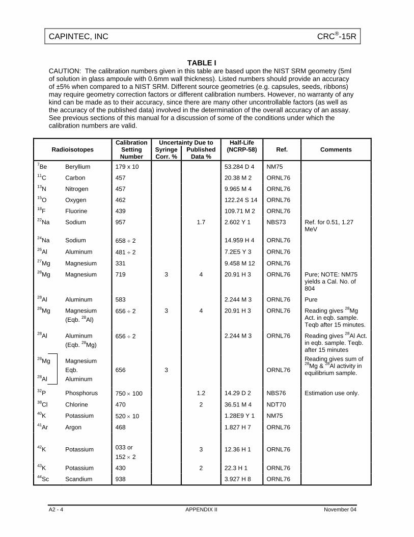
CAPINTEC, INC CRC®-15R
A2 - 4 APPENDIX II November 04
TABLE I CAUTION: The calibration numbers given in this table are based upon the NIST SRM geometry (5ml of solution in glass ampoule with 0.6mm wall thickness). Listed numbers should provide an accuracy of ±5% when compared to a NIST SRM. Different source geometries (e.g. capsules, seeds, ribbons) may require geometry correction factors or different calibration numbers. However, no warranty of any kind can be made as to their accuracy, since there are many other uncontrollable factors (as well as the accuracy of the published data) involved in the determination of the overall accuracy of an assay. See previous sections of this manual for a discussion of some of the conditions under which the calibration numbers are valid.
Calibration Uncertainty Due to Half-Life Radioisotopes Setting
Number SyringeCorr. %
Published Data %
(NCRP-58) Ref. Comments
7Be Beryllium 179 x 10 53.284 D 4 NM75 11C Carbon 457 20.38 M 2 ORNL76 13N Nitrogen 457 9.965 M 4 ORNL76 15O Oxygen 462 122.24 S 14 ORNL76 18F Fluorine 439 109.71 M 2 ORNL76 22Na Sodium 957 1.7 2.602 Y 1 NBS73 Ref. for 0.51, 1.27
MeV 24Na Sodium 658 ÷ 2 14.959 H 4 ORNL76 26Al Aluminum 481 ÷ 2 7.2E5 Y 3 ORNL76 27Mg Magnesium 331 9.458 M 12 ORNL76 28Mg Magnesium 719 3 4 20.91 H 3 ORNL76 Pure; NOTE: NM75
yields a Cal. No. of 804
28Al Aluminum 583 2.244 M 3 ORNL76 Pure 28Mg Magnesium
(Eqb. 28Al) 656 ÷ 2 3 4 20.91 H 3 ORNL76 Reading gives 28Mg
Act. in eqb. sample. Teqb after 15 minutes.
28Al Aluminum (Eqb. 28Mg)
656 ÷ 2 2.244 M 3 ORNL76 Reading gives 28Al Act. in eqb. sample. Teqb. after 15 minutes
28Mg 28Al
Magnesium Eqb. Aluminum
656
3
ORNL76
Reading gives sum of 28Mg & 28Al activity in equilibrium sample.
32P Phosphorus 750 × 100 1.2 14.29 D 2 NBS76 Estimation use only. 38Cl Chlorine 470 2 36.51 M 4 NDT70 40K Potassium 520 × 10 1.28E9 Y 1 NM75 41Ar Argon 468 1.827 H 7 ORNL76 42K Potassium 033 or
152 × 2 3 12.36 H 1 ORNL76
43K Potassium 430 2 22.3 H 1 ORNL76 44Sc Scandium 938 3.927 H 8 ORNL76
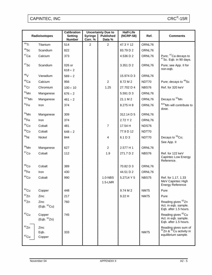
CAPINTEC, INC CRC®-15R
November 04 APPENDIX II A2 - 5
Calibration Uncertainty Due to Half-Life Radioisotopes Setting
Number SyringeCorr. %
Published Data %
(NCRP-58) Ref. Comments
44Ti Titanium 514 2 2 47.3 Y 12 ORNL76 46Sc Scandium 822 83.79 D 2 ORNL76 47Ca Calcium 373 4.536 D 2 ORNL76 Pure; 47Ca decays to
47Sc. Eqb. in 90 days. 47Sc Scandium 026 or
618 × 2 3.351 D 2 ORNL76 Pure; see App. II for
non-eqb.
48V Vanadium 569 ÷ 2 15.974 D 3 ORNL76 49Ca Calcium 956 2 8.72 M 2 NDT70 Pure; decays to 49Sc 51Cr Chromium 100 × 10 1.25 27.702 D 4 NBS76 Ref. for 320 keV 52Mn Manganese 676 ÷ 2 5.591 D 3 ORNL76 52mMn Manganese 461 ÷ 2 21.1 M 2 ORNL76 Decays to 52Mn 52Fe Iron 374 8.275 H 8 ORNL76 52mMn will contribute to
dose. 54Mn Manganese 309 312.14 D 5 ORNL76 55Fe Iron 374 2.72 Y 2 ORNL76 55Co Cobalt 481 7 17.54 H NDS76 56Co Cobalt 648 ÷ 2 77.9 D 12 NDT70 56Ni Nickel 844 4 6.1 D 3 NDT70 Decays to 56Co;
See App. II 56Mn Manganese 627 2 2.577 H 1 ORNL76 57Co Cobalt 112 1.9 271.7 D 2 NBS76 Ref. for 122 keV
Capintec Low Energy Reference.
58Co Cobalt 389 70.82 D 3 ORNL76 59Fe Iron 430 44.51 D 2 ORNL76 60Co Cobalt 990 1.0-NBS
1.5-LMR 5.2714 Y 5 NBS75 Ref. for 1.17, 1.33
MeV Capintec High Energy Reference
62Cu Copper 448 9.74 M 2 NM75 Pure 62Zn Zinc 217 9.22 H NM75 Pure 62Zn Zinc
(Eqb. 62Cu) 760 Reading gives 62Zn
Act. in eqb. sample. Eqb. after 1.5 hours.
62Cu Copper (Eqb. 62Zn)
745 Reading gives 62Cu Act. in eqb. sample. Eqb. after 1.5 hours.
62Zn 62Cu
Zinc Eqb. Copper
333
NM75
Reading gives sum of 62Zn & 62Cu activity in equilibrium sample.

CAPINTEC, INC CRC®-15R
A2 - 6 APPENDIX II November 04
Calibration Uncertainty Due to Half-Life Radioisotopes Setting
Number SyringeCorr. %
Published Data %
(NCRP-58) Ref. Comments
64Cu Copper 015 or 115 × 2
12.701 H 2 ORNL76
65Zn Zinc 172 243.9 D 1 ORNL76 66Ga Gallium 903 2 9.40 H 7 ORNL76 67Cu Copper 052 4 2.575 D 3 ORNL76 67Ga Gallium 100 1.4 3.261 D 1 NBS78 68Ga Gallium 416 68.0 M 2 ORNL76 69mZn Zinc 143 13.76 H 3 ORNL76 72As Arsenic 795 26.0 H 1 ORNL76 72Ga Gallium 470 ÷ 2 2 14.10 H 1 ORNL76 73As Arsenic 324 × 10 4 3 80.30 D 6 ORNL76 73Se Selenium 748 7.15 H 8 ORNL76 Decays to 73As. 74As Arsenic 304 5 17.78 D 3 ORNL76 75Se Selenium 258 2.5 119.8 D 1 NBS75 76As Arsenic 110 6 26.32 H 7 ORNL76 77As Arsenic 481 × 100 26 38.8 H 3 ORNL76 Estimation use only. 77Br Bromine 091 3 56 H 2 ORNL76 79Kr Krypton 050 3 35.04 H 10 ORNL76 81Rb Rubidium 174 4.58 H NM75 Pure 81mKr Krypton 915 × 10 13 S 1 NM75 Pure 81Rb 81mKr
Rubidium Eqb. Krypton
270
NM75
Reading gives act. of 81Rb or 81mKr in equilibrium sample. Eqb. after 2 minutes.
82Br Bromine 536 ÷ 2 2 35.34 H 2 ORNL76 82Rb Rubidium 504 1.273 M 2 NM75 84Rb Rubidium 347 32.77 D 4 NM75 85mKr Krypton 065 1 4.480 H 8 ORNL76 Decays to 85Kr 85Kr Krypton 031 × 100 2 10.72 Y 1 ORNL76 85Sr Strontium 193 1.0 64.854 D 3 NBS75 86Rb Rubidium 411 × 10 18.64 D 2 ORNL76 86Y Yttrium 711 ÷ 2 14.74 H 2 ORNL76 86Zr Zirconium 167 18 3 16.5 H 1 ORNL76 87Kr Krypton 250 6 76.3 M 5 ORNL76 87mSr Strontium 095 2.805 H 3 ORNL76 Pure 87Y Yttrium 170 1 80.3 H 3 ORNL76 Pure

CAPINTEC, INC CRC®-15R
November 04 APPENDIX II A2 - 7
Calibration Uncertainty Due to Half-Life Radioisotopes Setting
Number SyringeCorr. %
Published Data %
(NCRP-58) Ref. Comments
87Y Yttrium (Eqb. 87mSr)
357 ORNL76 Reading gives 87Y Act. in eqb. sample. Eqb. after 18 hours.
87Y 87mSr
Yttrium Eqb. Strontium
341
2
ORNL76
Reading gives sum of 87Y & 87mSr activity in equilibrium sample.
88Rb Rubidium 189 14 17.8 M 1 ORNL76 88Y Yttrium 465 ÷ 2 1.8 106.61 D 2 NBS73 89Rb Rubidium 768 1 15.2 M 1 ORNL76 90Y Yttrium 48 × 10 64.0 H 1 NIST92 Estimation use only. 91Y Yttrium 850 × 10 58.5 D 4 NDT70 Almost pure β decay.
Estimation use only. 94Nb Niobium 673 2.03E4 Y 16 ORNL76 95Nb Niobium 285 34.97 D 1 NDT70 Pure 95Zr Zirconium 271 64.02 D 5 NDT70 Pure 95Zr 95m95Nb
Zirconium Eqb. Niobium
145
95mNb 3.61 D 1
NDT70
Reading gives sum of 95mNb & 95Nb activity in equilibrium sample. Eqb. after 2 years.
97Nb Niobium 249 72.1 M 7 ORNL76 97Zr 97mNb
Zirconium Eqb. Niobium
341
12
16.90 H 5
ORNL76
Reading gives sum of 97Zr & 97mNb activity in equilibrium sample. Eqb. after 10 minutes.
97mNb Niobium 271 60 S 1 ORNL76 97Ru Ruthenium 116 15 2 2.9 D 1 ORNL76 Decays to 97mTc 97mTc Technetium 256 × 10 65 91.0 D NM75 Estimation use only. 99Mo Molybdenum
(in Std. Mo Kit) 080 × 5 or 246× 10 or 030 × 3.5
NTS78
99Mo Molybdenum (in CAP-MAC)
030 × 4 or 204 × 10
NBS78
99Mo Molybdenum (in MAC-S)
030 × 4 or 204 × 10
NBS78
99Mo Molybdenum (Eqb. 99mTc)
165 2 1.9 65.92 H 2 NBS78
99mTc Technetium 080 2 2.1 6.007 H 1 NBS76 99mTc Technetium
(in CAP-MAC) 042 2.1 6.007 H 1 NBS76

CAPINTEC, INC CRC®-15R
A2 - 8 APPENDIX II November 04
Calibration Uncertainty Due to Half-Life Radioisotopes Setting
Number SyringeCorr. %
Published Data %
(NCRP-58) Ref. Comments
99mTc Technetium (Eqb. 99Mo)
175 2 NBS78
99Mo 99mTc
Molybdenum Eqb. Technetium
145
2
NBS78
Reading gives sum of 99Mo & 99mTc activity in equilibrium sample.
103Pd Palladium 562 × 10 50 4 16.97 D 2 ORNL76 Pure 103Pd 103mRh
Palladium Eqb. Rhodium
634 × 10
50
5
ORNL76
Reading gives sum of 103Pd & 103mRh activity in equilibrium sample. Eqb. after 9 hours.
103mRh Rhodium 631 × 100 50 5 56.114 M 6 ORNL76 103Ru Ruthenium 165 50 3 39.26 D 2 ORNL76 103Ru 103mRh
Ruthenium Eqb. Rhodium
172
50
ORNL76
Reading gives sum of 103Ru & 103m,Rh activity in equilibrium sample. Eqb. after 9 hours.
106Ru Ruthenium (Eqb. 106Rh)
027 or 140 × 2
369 D 2 NDT70 Reading gives 106Ru Act. in eqb. sample. Eqb. after 5 minutes.
106Ru 106Rh
Ruthenium Eqb. Rhodium
480 × 10
369 D 2
NDT70
Reading gives sum of 106Ru & 106Rh activity in equilibrium sample.
108mAg Silver 830 3 127 Y 21 ORNL76 108Ag Silver 099 × 10 6 15 2.37 M 1 ORNL76 Large β contribution. 109Cd 109mAg
Cadmium Eqb. Silver
047 or 180 × 2
40 4 462.6 D 4 39.8 S
Reading gives act of 109Cd, 109mAg, or Total Act. in eqb. sample. Eqb. after 6 minutes.
109Pd 109mAg
Palladium Eqb. Silver
435 × 10
13.427 H 14 39.8 S
Reading gives act of 109Pd, 109mAg, or Total Act. in eqb. sample. Eqb. after 6 minutes.
110mAg Silver 554 ÷ 2 2 249.8 D 1 ORNL76 111Ag Silver 054 × 10 30 7.45 D 1 ORNL76 111In Indium 303 10 1.36 2.805 D 1 NBS77 113Sn Tin 022 or
129 × 2 35 5 115.08 D 3 MARTIN77 For pure 113Sn.
113mIn Indium 076 7 2 1.658 H 1 Separated for pure 113mIn.
113Sn 113mIn
Tin Eqb. Indium
180
15
3.2
NBS73,77
Reading gives act. of 113Sn, 113mIn, or Total Act. in eqb. sample. Eqb. after 15 hours.
115mIn Indium 058 15 2 4.486 H 4 ORNL76
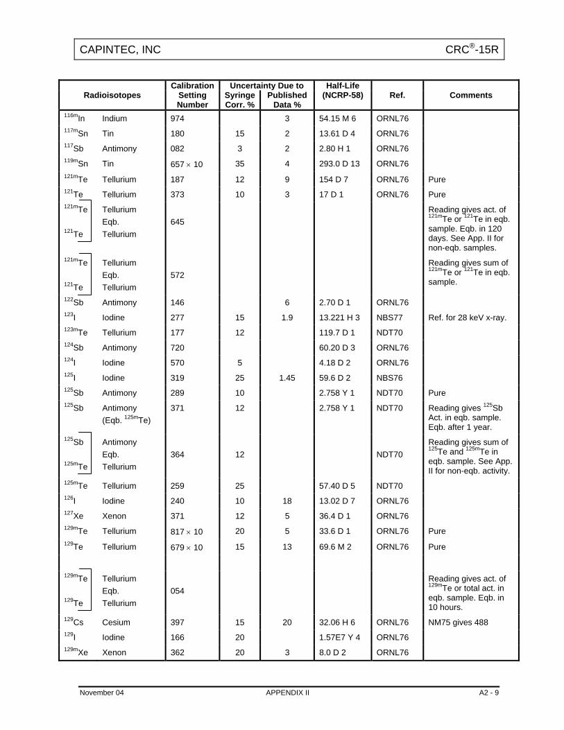
CAPINTEC, INC CRC®-15R
November 04 APPENDIX II A2 - 9
Calibration Uncertainty Due to Half-Life Radioisotopes Setting
Number SyringeCorr. %
Published Data %
(NCRP-58) Ref. Comments
116mIn Indium 974 3 54.15 M 6 ORNL76 117mSn Tin 180 15 2 13.61 D 4 ORNL76 117Sb Antimony 082 3 2 2.80 H 1 ORNL76 119mSn Tin 657 × 10 35 4 293.0 D 13 ORNL76 121mTe Tellurium 187 12 9 154 D 7 ORNL76 Pure 121Te Tellurium 373 10 3 17 D 1 ORNL76 Pure 121mTe 121Te
Tellurium Eqb. Tellurium
645
Reading gives act. of 121mTe or 121Te in eqb. sample. Eqb. in 120 days. See App. II for non-eqb. samples.
121mTe 121Te
Tellurium Eqb. Tellurium
572
Reading gives sum of 121mTe or 121Te in eqb. sample.
122Sb Antimony 146 6 2.70 D 1 ORNL76 123I Iodine 277 15 1.9 13.221 H 3 NBS77 Ref. for 28 keV x-ray. 123mTe Tellurium 177 12 119.7 D 1 NDT70 124Sb Antimony 720 60.20 D 3 ORNL76 124I Iodine 570 5 4.18 D 2 ORNL76 125I Iodine 319 25 1.45 59.6 D 2 NBS76 125Sb Antimony 289 10 2.758 Y 1 NDT70 Pure 125Sb Antimony
(Eqb. 125mTe) 371 12 2.758 Y 1 NDT70 Reading gives 125Sb
Act. in eqb. sample. Eqb. after 1 year.
125Sb 125mTe
Antimony Eqb. Tellurium
364
12
NDT70
Reading gives sum of 125Te and 125mTe in eqb. sample. See App. II for non-eqb. activity.
125mTe Tellurium 259 25 57.40 D 5 NDT70 126I Iodine 240 10 18 13.02 D 7 ORNL76 127Xe Xenon 371 12 5 36.4 D 1 ORNL76 129mTe Tellurium 817 × 10 20 5 33.6 D 1 ORNL76 Pure 129Te Tellurium 679 × 10 15 13 69.6 M 2 ORNL76 Pure
129mTe 129Te
Tellurium Eqb. Tellurium
054
Reading gives act. of 129mTe or total act. in eqb. sample. Eqb. in 10 hours.
129Cs Cesium 397 15 20 32.06 H 6 ORNL76 NM75 gives 488 129I Iodine 166 20 1.57E7 Y 4 ORNL76 129mXe Xenon 362 20 3 8.0 D 2 ORNL76

CAPINTEC, INC CRC®-15R
A2 - 10 APPENDIX II November 04
Calibration Uncertainty Due to Half-Life Radioisotopes Setting
Number SyringeCorr. %
Published Data %
(NCRP-58) Ref. Comments
130I Iodine 984 12.36 H 1 ORNL76 131I Iodine 151 1.65 8.021 D 1 NBS76 Decays to 131mXe.
1.1% feeding. 131mXe Xenon 089 20 3 11.9 D 1 ORNL76 131Cs Cesium 148 20 3 9.69 D 1 ORNL76 131Ba Barium 505 10 7 11.8 D 2 ORNL76 132Te Tellurium 315 10 5 76.3 H 2 ORNL76 Pure 132I Iodine 999 2.30 H 3 ORNL76 Pure 132Te Tellurium
(Eqb. 132I) 675 ÷ 2 Reading gives 132Te
Act. in eqb. sample. Eqb. after 1 day.
132I Iodine (Eqb. 132Te)
653 ÷ 2 Reading gives 132I Act. in eqb. sample.
132Te 132I
Tellurium Eqb. Iodine
663
ORNL76
Reading gives sum of 132Te and 132I in eqb. sample.
132Cs Cesium 485 10 2 6.475 D 10 ORNL76 133I Iodine 225 20.8 H 1 ORNL76 Decays to 133mXe. 133mXe Xenon 100 20 3 2.19 D 1 Decays to 133Xe. See
App. II. 133Xe Xenon 188 12 1.95 5.243 D 1 NBS76 133mBa Barium 132 12 3 38.9 H 1 ORNL76 Decays to 133Ba. 133Ba Barium 591 10 3 10.5 Y 1 ORNL76 134Te Tellurium 533 3 6 41.8 M 8 ORNL76 134mCs Cesium 037 or
160 × 2 15 2.91 H NM75 Decays to 134Cs.
134Cs Cesium 726 2.3 2.065 Y 1 NBS73 135mXe Xenon 181 3 15.29 M 3 ORNL76 Decays to 135Xe. See
App. II. 135Xe Xenon 085 2 9.09 H 1 ORNL76 135mBa Barium 130 15 4 28.7 H 2 ORNL76 136Cs Cesium 489 ÷ 2 4 13.1 D 1 ORNL76 137Cs 137mBa
Cesium Eqb. Barium
220
2.0 30.0 Y 2 2.553 M 1
NBS73
Ref: 661.6 & 32.9 keV. Reading gives 137Cs or Total Activity of eqb. sample. Often referred to as "Cs-137" Source.
139Ba Barium 445 × 10 5 12 82.8 M 2 ORNL76 139Ce Cerium 352 5 2.6 137.64 D 2 NBS73 Ref: 36.8 keV 141Ce Cerium 061 5 5 32.50 D 1 ORNL76
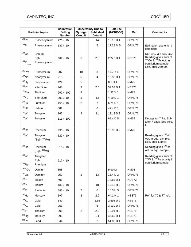
CAPINTEC, INC CRC®-15R
November 04 APPENDIX II A2 - 11
Calibration Uncertainty Due to Half-Life Radioisotopes Setting
Number SyringeCorr. %
Published Data %
(NCRP-58) Ref. Comments
142Pr Praseodymium 226 × 10 14 19.13 H 4 ORNL76 144Pr Praseodymium 137 × 10 5 17.28 M 5 ORNL76 Estimation use only. β
dominant. 144Ce 144Pr
Cerium Eqb. Praseodymium
387 × 10
5
2.8
285.0 D 1
NBS73
Ref: 36.7 & 133.5 keV. Reading gives sum of 144Ce & 144Pr Act. in equilibrium sample. Eqb. after 2 hours.
145Pm Promethium 207 10 3 17.7 Y 4 ORNL76 147Nd Neodymium 213 5 4 10.98 D 1 ORNL76 157Dy Dysprosium 424 5 8.1 H 1 NM75 169Yb Ytterbium 948 3 2.5 32.03 D 1 NBS78 171Tm Thulium 292 × 100 4 1.92 Y 1 NM75 175Yb Ytterbium 308 × 10 2 13 4.19 D 1 ORNL76 177Lu Lutetium 450 × 10 2 7 6.71 D 1 ORNL76 181Hf Hafnium 387 6 42.4 D 1 ORNL76 181W Tungsten 165 3 11 121.2 D 3 ORNL76 188W Tungsten 111 × 100 69.4 D 5 NM75 Decays to 188Re. Eqb.
after 7 days. See App. II
188Re Rhenium 496 × 10 16.98 H 2 NM75 188W Tungsten
(Eqb. 188Re) 522 × 10 Reading gives 188W
Act. in eqb. sample. Eqb. after 5 days.
188Re Rhenium (Eqb. 188W)
516 × 10 Reading gives 188Re Act. in eqb. sample.
188W 188Re
Tungsten Eqb. Rhenium
217 × 10
Reading gives sum of 188W & 188Re activity in equilibrium sample.
190mOs Osmium 858 9.90 M NM75 191Os Osmium 250 2 13 15.4 D 2 ORNL76 192Ir Iridium 408 73.83 D 1 NDS73 194Ir Iridium 469 × 10 18 19.15 H 3 ORNL76 197Pt Platinum 686 × 10 2 6 18.3 H 3 ORNL76 197Hg Mercury 197 2 2.9 64.1 H 1 NBS76 Ref. for 70 & 77 keV. 198Au Gold 149 1.65 2.696 D 2 NBS78 199Au Gold 053 6 3.139 D 7 ORNL76 201Tl Thallium 205 2 2.0 72.91 H 2 NBS76 203Hg Mercury 093 1.1 46.60 D 1 NBS73 203Pb Lead 344 2 51.88 H 1 ORNL76

CAPINTEC, INC CRC®-15R
A2 - 12 APPENDIX II November 04
Calibration Uncertainty Due to Half-Life Radioisotopes Setting
Number SyringeCorr. %
Published Data %
(NCRP-58) Ref. Comments
204Tl Thallium 420 × 100 2 2 3.78 Y 2 NDT70 207Bi Bismuth 846 1.7 32.2 Y 9 NBS73 Ref. for 1064, 569.7,
76.7, & 1772 keV. 208Tl Thallium 571 ÷ 2 3.053 M 4 NM75 212Pb Lead 101 10.64 H 1 NM75 Decays to 212Bi. Eqb.
after 1 hr. See App. II. 212Bi Bismuth 489 × 10 60.55 M 6 NM75 212Pb Lead
(Eqb. 212Bi) 158 Reading gives 212Pb
Act. in eqb. sample. Eqb. after 8 hours.
212Bi Bismuth (Eqb. 212Pb)
135 Reading gives 212Bi Act. in eqb. sample.
212Pb 212Bi
Lead Eqb. Bismuth
030 or 146 × 2
Reading gives sum of 212Pb & 212Bi activity in equilibrium sample.
224Ra Radium 646 × 100 3.66 D 4 NM75 226Ra Radium
+ chain of daughters
778 0.5 1600 Y 7 NBS73 Reading in grams. Commonly referred to as "Radium "Source. 1.025 g/Ci of Ra-226. See explanation of table entries in appendix I.
239Np Neptunium 147 6 2.355 D 4 ORNL76 241Am Americium 055 4 1 432.2 Y 5 LMR69 Ref. for 59.5 & 14 keV.

CAPINTEC, INC CRC®-15R
APPENDIX III
MULTIPLICATION FACTORS FOR NON-EQUILIBRIUM RADIOISOTOPES
The activity in a non-equilibrium sample can be determined by using the following equation:
A
B
BA
BA
BA
A
RRn21t
T TT T- exp - 1
T TT F + 1
A"" Purefor Number Cal. with ReadingMeter = A"" ofActivity
⎥⎦
⎤⎢⎣
⎡⎟⎟⎠
⎞⎜⎜⎝
⎛××
×−
−
where “A” and “B” are parent and daughter nuclide respectively, T's are half lives, and RA and RB are the chamber responses to the isotopes A and B, “t” is the elapsed time after the pure parent isotope was produced, and “F” is the decay branching ratio. The chamber response,”R,” may be obtained from the calibration number “N,” using the following equation:
0797.01075.8
N=R +
When the half-life of the parent nucleus (TA) is much shorter than that of the daughter nucleus (TR), the parent decays down to the daughter. After about 10 × TA, we can assume that only the daughter is left (except if the original activity of the parent was exceptionally high). The equation above for the Activity of “A” can be used to obtain the activity of the parent while it has measurable activity. Multiplication factors obtained by using the equation are given in the following tables for selected isotopes.
November 04 APPENDIX III A3 - 1

CAPINTEC, INC CRC®-15R
MULTIPLICATION FACTORS FOR Ca47 ACTIVITY MEASUREMENTS Use a Calibration Number of 373 and a multiplication factor as indicated in the following table to obtain Ca47 activity at time “t” days after an initially pure source of Ca47 is obtained.
Ca47 t
[days] Multiplication
Factor t
[days] Multiplication
Factor 0 1.000 12 0.672 1 0.950 14 0.648 2 0.906 16 0.627 3 0.869 18 0.609 4 0.836 20 0.594 5 0.806 25 0.566 6 0.781 30 0.545 7 0.757 40 0.519 8 0.737 50 0.496 9 0.718 100 0.485
10 0.701 150 0.484
MULTIPLICATION FACTORS FOR Ni56 ACTIVITY MEASUREMENTS Use a Calibration Number of 844 and a multiplication factor as indicated in the following table to obtain Ni56 activity at time “t” days after an initially pure source of Ni56 is obtained.
Ni56 t
[days] Multiplication
Factor t
[days] Multiplication
Factor 0 1.000 9 0.824 1 0.985 10 0.799 2 0.969 12 0.745 3 0.952 15 0.659 4 0.934 20 0.508 5 0.915 25 0.366 6 0.894 30 0.249 7 0.872 40 0.101 8 0.849 60 0.013
A3 - 2 APPENDIX III November 04

CAPINTEC, INC CRC®-15R
MULTIPLICATION FACTORS FOR Zn62 ACTIVITY MEASUREMENTS Use a Calibration Number of 217 and a multiplication factor as indicated in the following table to obtain Zn62 activity at time “t” minutes after an initially pure source of Zn62 is obtained.
Zn62 t
[minutes] Multiplication
Factor t
[minutes] Multiplication
Factor 0 1.000 45 0.368
10 0.526 60 0.361 20 0.425 75 0.359 30 0.389 90 0.358
MULTIPLICATION FACTORS FOR Y87 ACTIVITY MEASUREMENTS Use a Calibration Number of 170 and a multiplication factor as indicated in the following table to obtain Y87 activity at time “t” hours after an initially pure source of Y87 is obtained.
Y87 t
[hours] Multiplication
Factor t
[hours] Multiplication
Factor 0 1.000 5 0.664
0.25 0.960 6 0.644 0.50 0.926 8 0.618 0.75 0.893 10 0.602 1.00 0.866 12 0.593 1.5 0.820 18 0.582 2.0 0.784 24 0.580 3.0 0.729 48 0.579 4.0 0.691 ∞ 0.579
November 04 APPENDIX III A3 - 3
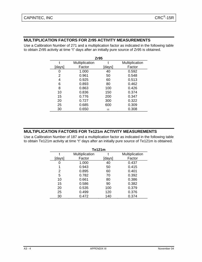
CAPINTEC, INC CRC®-15R
MULTIPLICATION FACTORS FOR Zr95 ACTIVITY MEASUREMENTS Use a Calibration Number of 271 and a multiplication factor as indicated in the following table to obtain Zr95 activity at time “t” days after an initially pure source of Zr95 is obtained.
Zr95 t
[days] Multiplication
Factor t
[days] Multiplication
Factor 0 1.000 40 0.592 2 0.961 50 0.548 4 0.925 60 0.513 6 0.893 80 0.462 8 0.863 100 0.426
10 0.836 150 0.374 15 0.776 200 0.347 20 0.727 300 0.322 25 0.685 600 0.309 30 0.650 ∞ 0.308
MULTIPLICATION FACTORS FOR Te121m ACTIVITY MEASUREMENTS Use a Calibration Number of 187 and a multiplication factor as indicated in the following table to obtain Te121m activity at time “t” days after an initially pure source of Te121m is obtained.
Te121m t
[days] Multiplication
Factor t
[days] Multiplication
Factor 0 1.000 40 0.437 1 0.943 50 0.415 2 0.895 60 0.401 5 0.782 70 0.392
10 0.661 80 0.386 15 0.586 90 0.382 20 0.535 100 0.379 25 0.499 120 0.376 30 0.472 140 0.374
A3 - 4 APPENDIX III November 04

CAPINTEC, INC CRC®-15R
MULTIPLICATION FACTORS FOR Sb125 ACTIVITY MEASUREMENTS Use a Calibration Number of 289 and a multiplication factor as indicated in the following table to obtain Sb125 activity at time “t” days after an initially pure source of Sb125 is obtained.
Sb125 t
[days] Multiplication
Factor t
[days] Multiplication
Factor 0 1.000 90 0.878
10 0.977 120 0.861 20 0.958 150 0.849 30 0.941 180 0.841 40 0.927 360 0.824 50 0.914 540 0.822 60 0.903 ∞ 0.821
MULTIPLICATION FACTORS FOR Te129m ACTIVITY MEASUREMENTS Use a Calibration Number of 817 and a multiplication factor as indicated in the following table to obtain Te129m activity at time “t” hours after an initially pure source of Te129m is obtained.
Te129m t
[hours] Multiplication
Factor t
[hours] Multiplication
Factor 0 10.0 6 6.55 1 8.04 8 6.50 2 7.25 10 6.49 4 6.701 12 6.48 Equilibrium
November 04 APPENDIX III A3 - 5

CAPINTEC, INC CRC®-15R
MULTIPLICATION FACTORS FOR Te132 ACTIVITY MEASUREMENTS Use a Calibration Number of 315 and a multiplication factor as indicated in the following table to obtain Te132 activity at time “t” hours after an initially pure source of Te132 is obtained.
Te132 t
[hours] Multiplication
Factor t
[hours] Multiplication
Factor 0 1.000 4 0.342
0.25 0.836 5 0.318 0.50 0.725 10 0.275 1.00 0.586 15 0.266 2.00 0.447 20 0.265 3.00 0.380 24 0.264
Equilibrium
MULTIPLICATION FACTORS FOR Xe133m ACTIVITY MEASUREMENTS Use a Calibration Number of 100 and a multiplication factor as indicated in the following table to obtain Xe133m activity at time “t” days after an initially pure source of Xe133m is obtained.
Xe133m t
[days] Multiplication
Factor t
[days] Multiplication
Factor 0 1.000 4 0.465 1 0.824 5 0.385 2 0.680 10 0.151 3 0.562 20 0.024
A3 - 6 APPENDIX III November 04
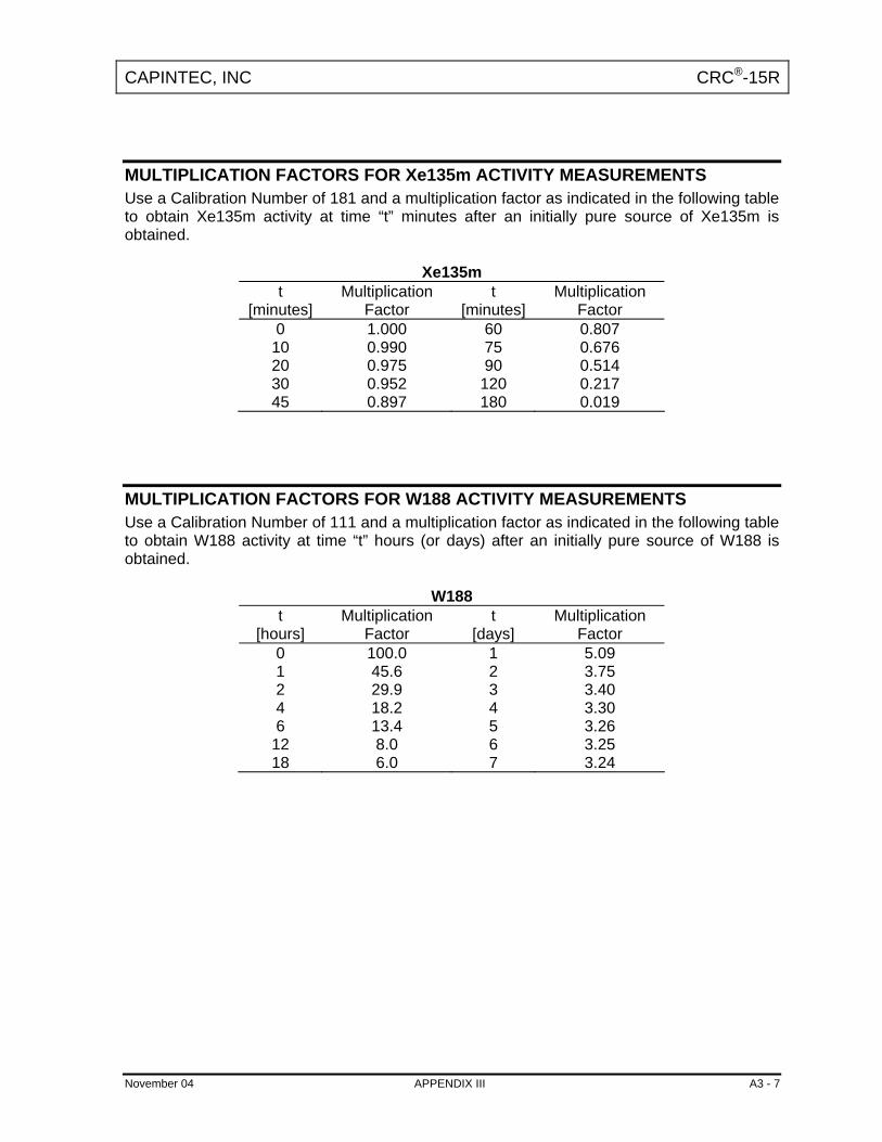
CAPINTEC, INC CRC®-15R
MULTIPLICATION FACTORS FOR Xe135m ACTIVITY MEASUREMENTS Use a Calibration Number of 181 and a multiplication factor as indicated in the following table to obtain Xe135m activity at time “t” minutes after an initially pure source of Xe135m is obtained.
Xe135m t
[minutes] Multiplication
Factor t
[minutes] Multiplication
Factor 0 1.000 60 0.807
10 0.990 75 0.676 20 0.975 90 0.514 30 0.952 120 0.217 45 0.897 180 0.019
MULTIPLICATION FACTORS FOR W188 ACTIVITY MEASUREMENTS Use a Calibration Number of 111 and a multiplication factor as indicated in the following table to obtain W188 activity at time “t” hours (or days) after an initially pure source of W188 is obtained.
W188 t
[hours] Multiplication
Factor t
[days] Multiplication
Factor 0 100.0 1 5.09 1 45.6 2 3.75 2 29.9 3 3.40 4 18.2 4 3.30 6 13.4 5 3.26
12 8.0 6 3.25 18 6.0 7 3.24
November 04 APPENDIX III A3 - 7

CAPINTEC, INC CRC®-15R
MULTIPLICATION FACTORS FOR Pb212 ACTIVITY MEASUREMENTS Use a Calibration Number of 101 and a multiplication factor as indicated in the following table to obtain Pb212 activity at time “t” hours after an initially pure source of Pb212 is obtained.
Pb212 t
[hours] Multiplication
Factor t
[hours] Multiplication
Factor 0 1.000 5 0.772
0.5 0.924 6 0.768 1.0 0.875 7 0.766 2.0 0.820 8 0.765 3.0 0.793 9 0.765 4.0 0.779 10 0.764
Equilibrium
A3 - 8 APPENDIX III November 04

CAPINTEC, INC CRC®-15R
APPENDIX IV
OPERATIONAL SUMMARY Thank you for choosing CAPINTEC. This “Start-Up” aid is designed to allow you to use the CRC-15R to perform immediate nuclide measurements.
QUALITY CONTROL & DAILY TESTS Prior to making any activity measurements, Daily Tests must be performed.
Press . You will see this screen: . Select Daily Test by pressing . The Daily Tests include Auto Zero, Background Adjustment, System Test, Data Check, and Constancy. You will be required to perform your normal or manual Accuracy and Constancy tests if you have not entered your Test Source data in the CRC®-15R. To enter Test Source data, see CHAPTER 5: SYSTEM INITIALIZATION, SECTION: ENTERING TEST SOURCE DATA.
1. Daily Test2. System 3. Accuracy 1
- TEST
BACKGROUND ADJUSTMENT Background adjustment is performed automatically in the Daily Test sequence. It can also be performed by pressing the Background key.
To perform a Background Adjustment, press . You will see the following BKG
screen: . Make sure that no sources are in the vicinity of the chamber. Press any key, other than the HOME key, to begin. At the end of the measuring period, you will see the message “OK - ENTER to accept”. Press the ENTER key. The background value will be stored and automatically subtracted from all measurements.
BACKGROUND NO SOURCES
Any key to continue
MEASURING NUCLIDE ACTIVITY To measure the activity of a sample, simply place the sample in the dipper, lower it into the well, and select the nuclide from the keypad.
November 04 APPENDIX IV A4 - 1

CAPINTEC, INC CRC®-15R
SELECTING A NUCLIDE FOR MEASUREMENT When measuring the activity of a nuclide, you must indicate the nuclide being measured. This can be accomplished in four (4) simple ways:
1. PRE-SET KEYS: You can select from 10 pre-defined keys. Each key is labeled to indicate the corresponding nuclide as shown below.
Mo Assay
Co 57
Ga 67
Tc99m
In111
I123
I 131
Xe133
Tl201
F18
Example: Measuring Tc99m. Place the sample in the well and press . Tc
99m
The activity for Tc99m is automatically displayed. 2. USER DEFINED KEYS: The CRC®-15R has 4 user defined keys. You can
assign nuclides to these keys. (See: CHAPTER 5: SYSTEM INITIALIZATION, SECTION: USER KEY ASSIGNMENT)
3. NUCLIDE KEY: The Nuclide Key allows you to select a nuclide from the list of 85
nuclides that have been stored in the memory. Simply press the NUCL key and use the keypad to specify the nuclide. After selecting the values press the ENTER key.
Example: Co60 Press . Press . ABC
2 MNO
6 QZ 0
MNO6 NUCL
Press . ENTER
4. CALIBRATION NUMBERS: To measure the activity of a nuclide that is not
stored in the memory, pre-set keys, or user defined keys, press the CAL# key, enter the calibration number for the nuclide, and press the ENTER key. The activity can then be measured. Simply place the sample in the chamber.
Note: Calibration numbers are listed in Appendix II.
Example: Press . Enter the calibration number. Press . CAL# EN TER
A4 - 2 APPENDIX IV November 04

CAPINTEC, INC CRC®-15R
FUTURE ACTIVITY The CRC®-15R has a special feature that allows you to automatically determine the activity of a sample at some point in the future.
Example: Press . Enter the new time & date in the 24 hour format. TIME
Press . The “FUTURE” activity is displayed. EN TER
ENTER TEST DATA (See: CHAPTER 5: SYSTEM INITIALIZATION, SECTION: ENTERING TEST SOURCE DATA)
The Test Data must be entered from the main Utility Menu. To access this menu,
press to get to the Chamber measurement screen. Press to HOME UTIL
display the Utilities Menu. Press , , , , :4. Setup :
:4. Other :
Enter Password (last three (3) digits of the serial number)
: 2. Test Sources :
.
: 4. Cs137 :
If the Test Source data has been entered in the system, verify that these are the dates from your Cs137 Test Source and press Y. Press N if the dates are incorrect or if no source data has been entered in the system. The system then displays:
Input the serial number of the Test Source and press ENTER. Input the Calibration Day and press ENTER. Input the Calibration Activity and press ENTER. Answer (Y)es or (N)o to “USE FOR DAILY?”.
CS137 ENTER S/N
The system will display the inserted data. Verify the data and confirm with Y. To correct any errors, press N.
Press . this brings you back to the Measurement Screen. HOME
November 04 APPENDIX IV A4 - 3


CAPINTEC, INC CRC®-15R
INDEX A Accuracy Test, 7-5 Activity
Specifying a Nuclide, 8-1 ARROW Keys, 3-3 Auto Zero, 7-1 B Background (Chamber), 7-3 BKG Key, 3-2 BSP Key, 3-3 C CAL # Key, 3-2 Calibration Numbers
changing, 5-14 determining, 5-13
CAPMAC, 4-6, 5-16 CE Key, 3-3 Ci / Bq
Choosing, 5-3 Conversion, 9-1
Ci / Bq Key, 3-3 Constancy Test, 7-5 D Date
Entering, 5-1, 5-18 Decay Calculation, 9-2 Diagnostics, 6-1, 7-7 E ENTER Key, 3-3 H HOME Key, 3-2 I Installation, 4-1 M Measurement
Activity at a Different Time, 8-3 Nuclide Specification, 8-1
Moly Assay, 4-6, 5-16
Moly Assay Mo/Tc Limit, 5-17
Moly Assay results, 8-9
N NUCL Key, 8-2 NUCL KEY, 3-2 Nuclide Keys, 3-2 Nuclides
adding, 4-6, 5-11 deleting, 5-14 specification, 8-1
Number / Letter Keys, 3-2 P Preliminary Procedures, 2-3 R Receiving Condition Examination, 4-1 Requirements
Environment, 2-3, 4-4 Power, 2-4, 4-4
S System Test, 7-4 T Test
Report, 6-2 Test Source
Daily usage, 5-7 Serial Number, 5-6
Test Source, 4-6, 5-4 Time
Entering, 5-1, 5-18 TIME key, 8-3 U Unpacking, 4-1 User Keys, 3-2
Assignment, 4-6, 5-9 UTIL key, 2-2 UTIL Key, 3-2
November 04 INDEX i - 1

CAPINTEC, INC CRC®-15R
V Voltage
High, 1-2
Y Yes or No, 3-4
i - 2 INDEX November 04

NEW PRODUCT WARRANTY
Conditions and Limitations
CAPINTEC warrants our products to be free from defects in material and workmanship for a period of 12 months after delivery to the original buyer (unless indicated otherwise). Our obligation under this warranty is limited to servicing or adjusting products returned to our factory for that purpose promptly upon any claim under this warranty, provided our examination discloses to our satisfaction that the affected parts were originally defective and have not been subjected to misuse, abuse, mishandling or improper operation. This warranty extends to every part of the product except batteries, fuses, ink, magnetic storage media, toner, transistors, tubes or any other normally consumable item. In no event shall we liable for transportation, installation, adjustment or any other expenses which may arise in connection with such products or their servicing or adjustment. This warranty is expressly in lieu of any other express or implied warranties, and we make no warranty that the products sold herein are merchantable or are suitable for any particular purpose. The benefits of this warranty shall extend only to the buyer and to none other. We shall have no liability of any nature arising out of the use or application of the product in conformity with this warranty. If the product shall fail to perform in conformity with the warranty made herein, we shall be liable solely for the repair and replacement of the product as provided hereinabove, and shall have no other liability in respect of such failure or performance, or any consequences therefrom, including, without limitation, business impairment or loss, personal injury or property damage. No agent, employee, or representative of ours has any authority to bind us to any representation or warranty concerning the product sold herein, and unless a representation or warranty made by an agent, employee or representative is specifically included herein, it shall not be enforceable by the buyer. No waiver, alteration or modification of the foregoing conditions shall be valid, unless made in writing and signed by an executive officer of our corporation.