RADIO TEST REPORT For Happy Plugs AB True wireless earbuds ...
21
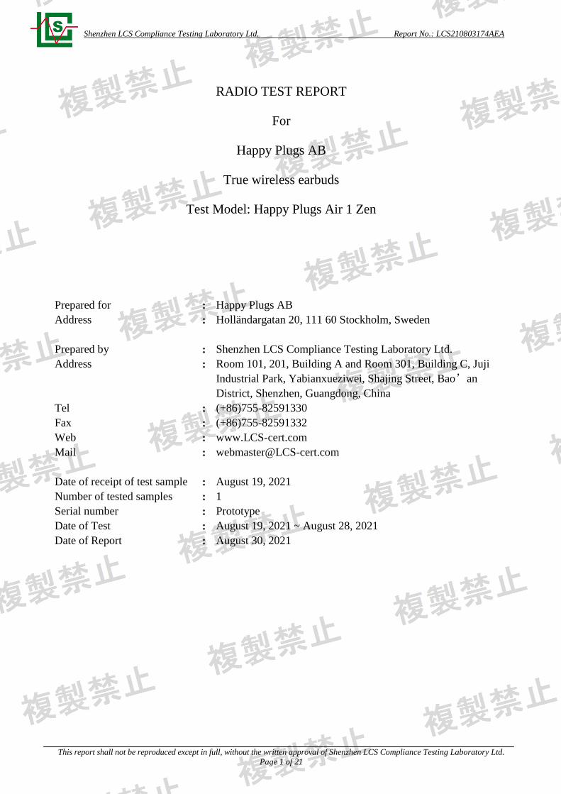
Shenzhen LCS Compliance Testing Laboratory Ltd. Report No.: LCS210803174AEA This report shall not be reproduced except in full, without the written approval of Shenzhen LCS Compliance Testing Laboratory Ltd. Page 1 of 21 RADIO TEST REPORT For Happy Plugs AB True wireless earbuds Test Model: Happy Plugs Air 1 Zen Prepared for : Happy Plugs AB Address : Holländargatan 20, 111 60 Stockholm, Sweden Prepared by : Shenzhen LCS Compliance Testing Laboratory Ltd. Address : Room 101, 201, Building A and Room 301, Building C, Juji Industrial Park, Yabianxueziwei, Shajing Street, Bao’an District, Shenzhen, Guangdong, China Tel : (+86)755-82591330 Fax : (+86)755-82591332 Web : www.LCS-cert.com Mail : [email protected] Date of receipt of test sample : August 19, 2021 Number of tested samples : 1 Serial number : Prototype Date of Test : August 19, 2021 ~ August 28, 2021 Date of Report : August 30, 2021
Transcript of RADIO TEST REPORT For Happy Plugs AB True wireless earbuds ...
Shenzhen LCS Compliance Testing Laboratory Ltd. Report No.: LCS210803174AEA
This report shall not be reproduced except in full, without the written approval of Shenzhen LCS Compliance Testing Laboratory Ltd.
Page 1 of 21
RADIO TEST REPORT
For
Happy Plugs AB
True wireless earbuds
Test Model: Happy Plugs Air 1 Zen
Prepared for : Happy Plugs AB
Address : Holländargatan 20, 111 60 Stockholm, Sweden
Prepared by : Shenzhen LCS Compliance Testing Laboratory Ltd.
Address : Room 101, 201, Building A and Room 301, Building C, Juji
Industrial Park, Yabianxueziwei, Shajing Street, Bao’an
District, Shenzhen, Guangdong, China
Tel : (+86)755-82591330
Fax : (+86)755-82591332
Web : www.LCS-cert.com
Mail : [email protected]
Date of receipt of test sample : August 19, 2021
Number of tested samples : 1
Serial number : Prototype
Date of Test : August 19, 2021 ~ August 28, 2021
Date of Report : August 30, 2021
Shenzhen LCS Compliance Testing Laboratory Ltd. Report No.: LCS210803174AEA
This report shall not be reproduced except in full, without the written approval of Shenzhen LCS Compliance Testing Laboratory Ltd.
Page 2 of 21
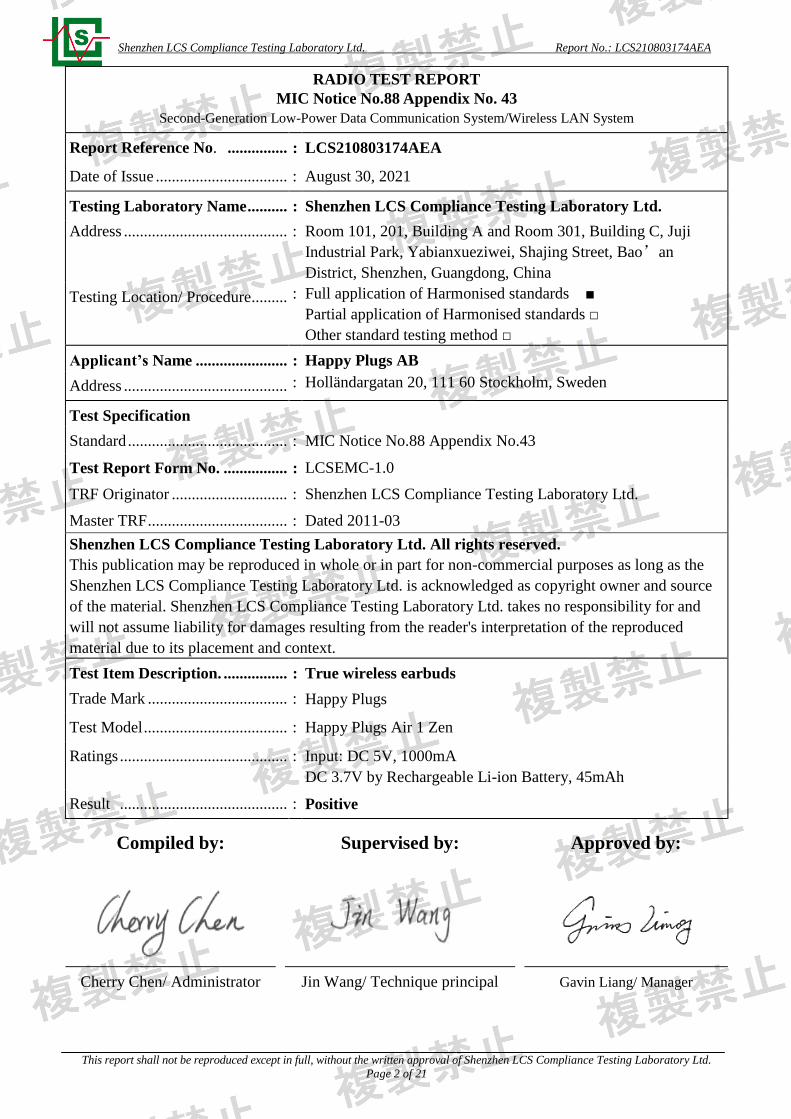
RADIO TEST REPORT
MIC Notice No.88 Appendix No. 43
Second-Generation Low-Power Data Communication System/Wireless LAN System
Report Reference No. ............... : LCS210803174AEA
Date of Issue ................................. : August 30, 2021
Testing Laboratory Name .......... : Shenzhen LCS Compliance Testing Laboratory Ltd.
Address ......................................................................................................................................... : Room 101, 201, Building A and Room 301, Building C, Juji
Industrial Park, Yabianxueziwei, Shajing Street, Bao’an
District, Shenzhen, Guangdong, China
Testing Location/ Procedure ......... :
Full application of Harmonised standards ■
Partial application of Harmonised standards □
Other standard testing method □
Applicant’s Name ....................... : Happy Plugs AB
Address ......................................... : Holländargatan 20, 111 60 Stockholm, Sweden
Test Specification
Standard ........................................ : MIC Notice No.88 Appendix No.43
Test Report Form No. ................ : LCSEMC-1.0
TRF Originator ............................. : Shenzhen LCS Compliance Testing Laboratory Ltd.
Master TRF ................................... : Dated 2011-03
Shenzhen LCS Compliance Testing Laboratory Ltd. All rights reserved.
This publication may be reproduced in whole or in part for non-commercial purposes as long as the
Shenzhen LCS Compliance Testing Laboratory Ltd. is acknowledged as copyright owner and source
of the material. Shenzhen LCS Compliance Testing Laboratory Ltd. takes no responsibility for and
will not assume liability for damages resulting from the reader's interpretation of the reproduced
material due to its placement and context.
Test Item Description. ................ : True wireless earbuds
Trade Mark ................................... : Happy Plugs
Test Model .................................... : Happy Plugs Air 1 Zen
Ratings .......................................... : Input: DC 5V, 1000mA
DC 3.7V by Rechargeable Li-ion Battery, 45mAh
Result .......................................... : Positive
Compiled by:
Supervised by:
Approved by:
Cherry Chen/ Administrator Jin Wang/ Technique principal Gavin Liang/ Manager

Shenzhen LCS Compliance Testing Laboratory Ltd. Report No.: LCS210803174AEA
This report shall not be reproduced except in full, without the written approval of Shenzhen LCS Compliance Testing Laboratory Ltd.
Page 3 of 21
RADIO -- TEST REPORT
Test Result Positive
The test report merely corresponds to the test sample.
It is not permitted to copy extracts of these test result without the written permission of the test laboratory.
Test Report No. : LCS210803174AEA
August 30, 2021
Date of issue
Test Model.............................. : Happy Plugs Air 1 Zen
EUT......................................... : True wireless earbuds
Applicant............................... : Happy Plugs AB
Address.................................. : Holländargatan 20, 111 60 Stockholm, Sweden
Telephone............................... : /
Fax.......................................... : /
Manufacturer........................ : Dongguan meiyin technology co.LTD
Address................................... : Building C, No. 1, Zhiquan Hi-tech park road, Dongkeng town,
Dongguan city
Telephone............................... : /
Fax.......................................... : /
Factory................................... : Dongguan meiyin technology co.LTD
Address................................... : Building C, No. 1, Zhiquan Hi-tech park road, Dongkeng town,
Dongguan city
Telephone............................... : /
Fax.......................................... : /

Shenzhen LCS Compliance Testing Laboratory Ltd. Report No.: LCS210803174AEA
This report shall not be reproduced except in full, without the written approval of Shenzhen LCS Compliance Testing Laboratory Ltd.
Page 4 of 21
Revision History Revision Issue Date Revisions Revised By
000 August 30, 2021 Initial Issue Gavin Liang
Shenzhen LCS Compliance Testing Laboratory Ltd. Report No.: LCS210803174AEA
This report shall not be reproduced except in full, without the written approval of Shenzhen LCS Compliance Testing Laboratory Ltd.
Page 5 of 21
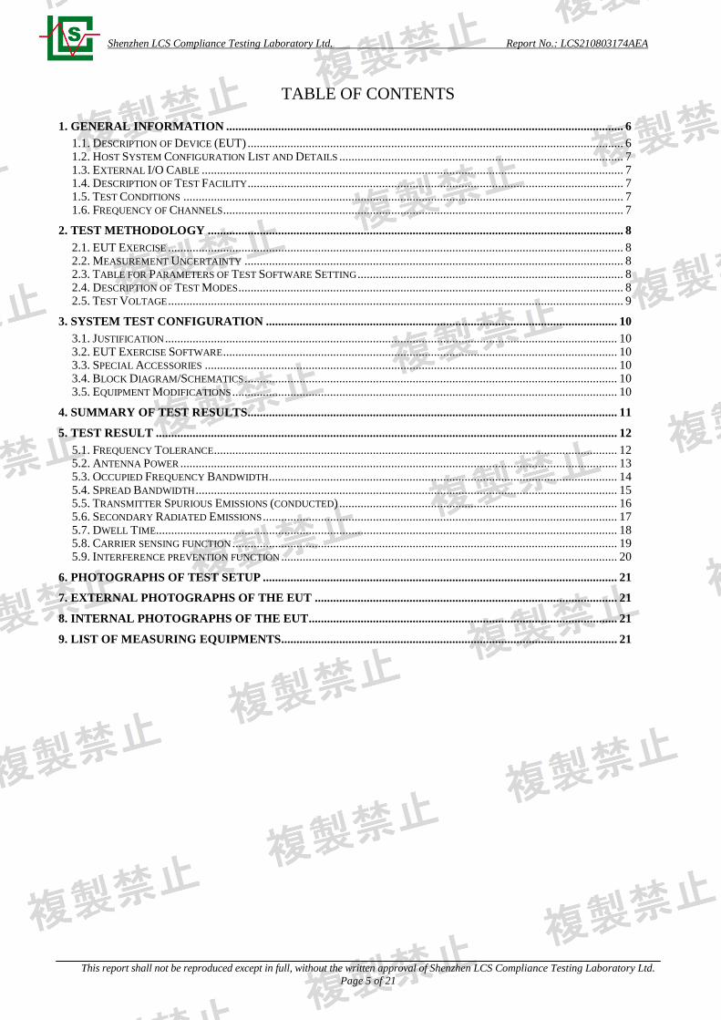
TABLE OF CONTENTS
1. GENERAL INFORMATION .................................................................................................................................. 6
1.1. DESCRIPTION OF DEVICE (EUT) ........................................................................................................................... 6 1.2. HOST SYSTEM CONFIGURATION LIST AND DETAILS ............................................................................................. 7 1.3. EXTERNAL I/O CABLE .......................................................................................................................................... 7 1.4. DESCRIPTION OF TEST FACILITY ........................................................................................................................... 7 1.5. TEST CONDITIONS ................................................................................................................................................ 7 1.6. FREQUENCY OF CHANNELS ................................................................................................................................... 7
2. TEST METHODOLOGY ........................................................................................................................................ 8
2.1. EUT EXERCISE ..................................................................................................................................................... 8 2.2. MEASUREMENT UNCERTAINTY ............................................................................................................................ 8 2.3. TABLE FOR PARAMETERS OF TEST SOFTWARE SETTING ....................................................................................... 8 2.4. DESCRIPTION OF TEST MODES .............................................................................................................................. 8 2.5. TEST VOLTAGE ..................................................................................................................................................... 9
3. SYSTEM TEST CONFIGURATION ................................................................................................................... 10
3.1. JUSTIFICATION .................................................................................................................................................... 10 3.2. EUT EXERCISE SOFTWARE ................................................................................................................................. 10 3.3. SPECIAL ACCESSORIES ....................................................................................................................................... 10 3.4. BLOCK DIAGRAM/SCHEMATICS .......................................................................................................................... 10 3.5. EQUIPMENT MODIFICATIONS .............................................................................................................................. 10
4. SUMMARY OF TEST RESULTS......................................................................................................................... 11
5. TEST RESULT ....................................................................................................................................................... 12
5.1. FREQUENCY TOLERANCE .................................................................................................................................... 12 5.2. ANTENNA POWER ............................................................................................................................................... 13 5.3. OCCUPIED FREQUENCY BANDWIDTH .................................................................................................................. 14 5.4. SPREAD BANDWIDTH .......................................................................................................................................... 15 5.5. TRANSMITTER SPURIOUS EMISSIONS (CONDUCTED) ........................................................................................... 16 5.6. SECONDARY RADIATED EMISSIONS .................................................................................................................... 17 5.7. DWELL TIME....................................................................................................................................................... 18 5.8. CARRIER SENSING FUNCTION .............................................................................................................................. 19 5.9. INTERFERENCE PREVENTION FUNCTION .............................................................................................................. 20
6. PHOTOGRAPHS OF TEST SETUP .................................................................................................................... 21
7. EXTERNAL PHOTOGRAPHS OF THE EUT ................................................................................................... 21
8. INTERNAL PHOTOGRAPHS OF THE EUT ..................................................................................................... 21
9. LIST OF MEASURING EQUIPMENTS.............................................................................................................. 21

Shenzhen LCS Compliance Testing Laboratory Ltd. Report No.: LCS210803174AEA
This report shall not be reproduced except in full, without the written approval of Shenzhen LCS Compliance Testing Laboratory Ltd.
Page 6 of 21
1. GENERAL INFORMATION
1.1. Description of Device (EUT)
EUT : True wireless earbuds
Test Model : Happy Plugs Air 1 Zen
Power Supply : Input: DC 5V, 1000mA
DC 3.7V by Rechargeable Li-ion Battery, 45mAh
Hardware Version : B96-BES2500IU-V2.0
Software Version : B96_SDK081_20210823_V005
Bluetooth
Frequency Range : 2402-2480MHz for Bluetooth
(79 channels for Bluetooth V5.0(BDR/EDR)
Channel Frequency=2402+(K-1), K=1, 2, 3 ……79
Declared Antenna Power : Bluetooth V5.0(BDR/EDR): 2.5mW/MHz
Modulation Technology : Bluetooth V5.0(BDR/EDR): GFSK, π/4-DQPSK, 8-DPSK
Data Rate : Bluetooth V5.0(BDR/EDR): 1/2/3Mbps
Antenna Description : Internal Antenna, 0.69dBi(Max)
Shenzhen LCS Compliance Testing Laboratory Ltd. Report No.: LCS210803174AEA
This report shall not be reproduced except in full, without the written approval of Shenzhen LCS Compliance Testing Laboratory Ltd.
Page 7 of 21
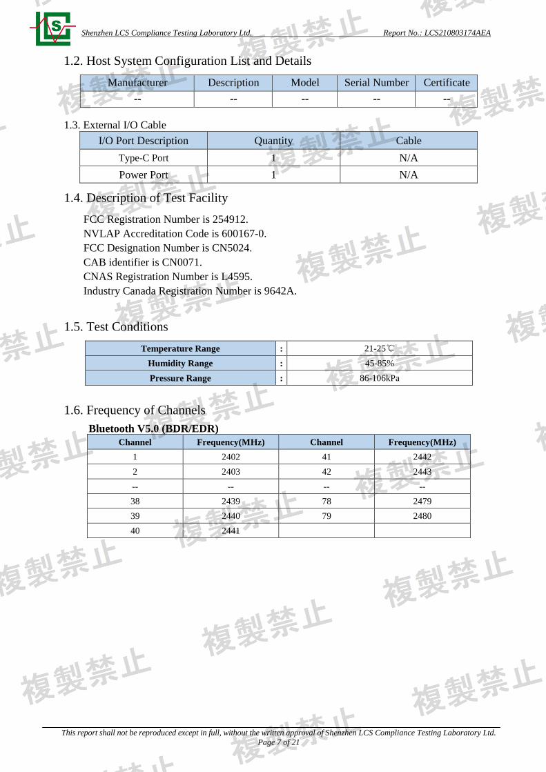
1.2. Host System Configuration List and Details
Manufacturer Description Model Serial Number Certificate
-- -- -- -- --
1.3. External I/O Cable
I/O Port Description Quantity Cable
Type-C Port 1 N/A
Power Port 1 N/A
1.4. Description of Test Facility
FCC Registration Number is 254912.
NVLAP Accreditation Code is 600167-0.
FCC Designation Number is CN5024.
CAB identifier is CN0071.
CNAS Registration Number is L4595.
Industry Canada Registration Number is 9642A.
1.5. Test Conditions
Temperature Range : 21-25℃
Humidity Range : 45-85%
Pressure Range : 86-106kPa
1.6. Frequency of Channels
Bluetooth V5.0 (BDR/EDR)
Channel Frequency(MHz) Channel Frequency(MHz)
1 2402 41 2442
2 2403 42 2443
-- -- -- --
38 2439 78 2479
39 2440 79 2480
40 2441
Shenzhen LCS Compliance Testing Laboratory Ltd. Report No.: LCS210803174AEA
This report shall not be reproduced except in full, without the written approval of Shenzhen LCS Compliance Testing Laboratory Ltd.
Page 8 of 21
2. TEST METHODOLOGY
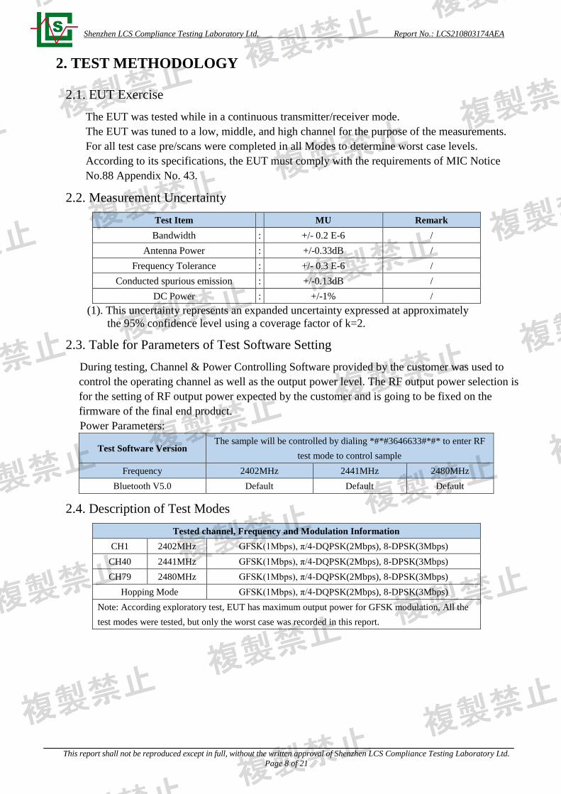
2.1. EUT Exercise
The EUT was tested while in a continuous transmitter/receiver mode.
The EUT was tuned to a low, middle, and high channel for the purpose of the measurements.
For all test case pre/scans were completed in all Modes to determine worst case levels.
According to its specifications, the EUT must comply with the requirements of MIC Notice
No.88 Appendix No. 43.
2.2. Measurement Uncertainty
Test Item MU Remark
Bandwidth : +/- 0.2 E-6 /
Antenna Power : +/-0.33dB /
Frequency Tolerance : +/- 0.3 E-6 /
Conducted spurious emission : +/-0.13dB /
DC Power : +/-1% /
(1). This uncertainty represents an expanded uncertainty expressed at approximately
the 95% confidence level using a coverage factor of k=2.
2.3. Table for Parameters of Test Software Setting
During testing, Channel & Power Controlling Software provided by the customer was used to
control the operating channel as well as the output power level. The RF output power selection is
for the setting of RF output power expected by the customer and is going to be fixed on the
firmware of the final end product.
Power Parameters:
Test Software Version The sample will be controlled by dialing *#*#3646633#*#* to enter RF
test mode to control sample
Frequency 2402MHz 2441MHz 2480MHz
Bluetooth V5.0 Default Default Default
2.4. Description of Test Modes
Tested channel, Frequency and Modulation Information
CH1 2402MHz GFSK(1Mbps), π/4-DQPSK(2Mbps), 8-DPSK(3Mbps)
CH40 2441MHz GFSK(1Mbps), π/4-DQPSK(2Mbps), 8-DPSK(3Mbps)
CH79 2480MHz GFSK(1Mbps), π/4-DQPSK(2Mbps), 8-DPSK(3Mbps)
Hopping Mode GFSK(1Mbps), π/4-DQPSK(2Mbps), 8-DPSK(3Mbps)
Note: According exploratory test, EUT has maximum output power for GFSK modulation, All the
test modes were tested, but only the worst case was recorded in this report.
Shenzhen LCS Compliance Testing Laboratory Ltd. Report No.: LCS210803174AEA
This report shall not be reproduced except in full, without the written approval of Shenzhen LCS Compliance Testing Laboratory Ltd.
Page 9 of 21
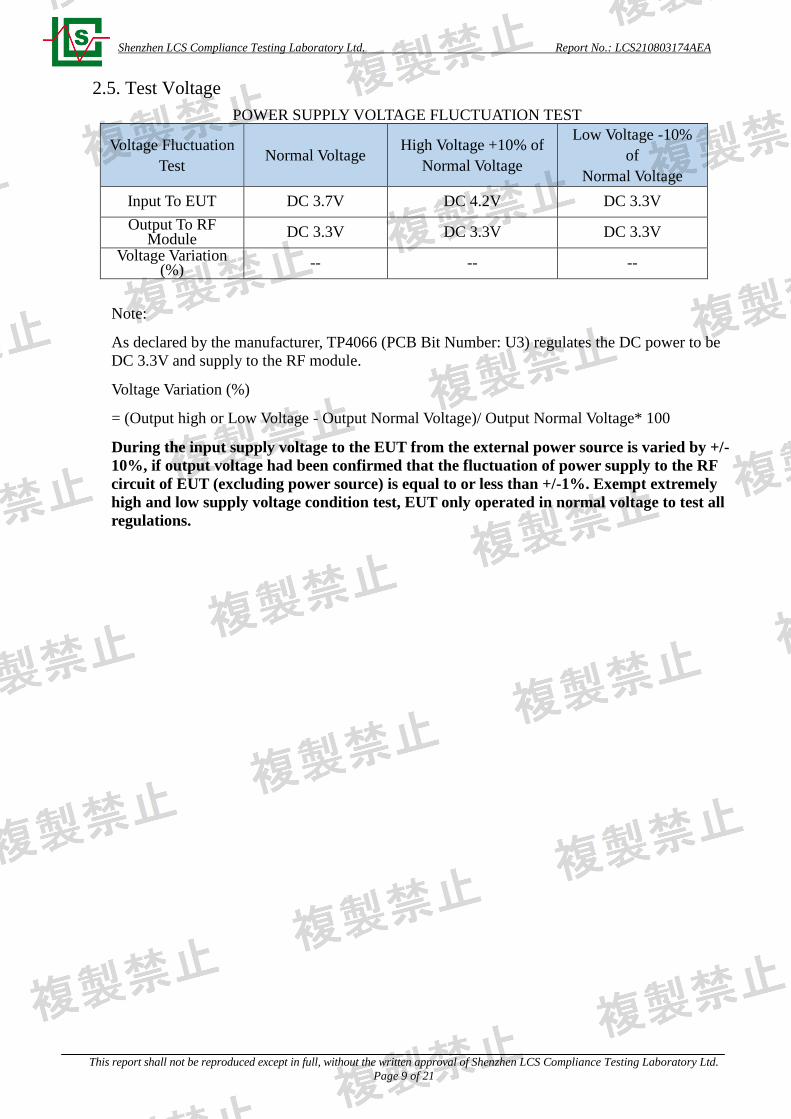
2.5. Test Voltage
POWER SUPPLY VOLTAGE FLUCTUATION TEST
Voltage Fluctuation
Test Normal Voltage
High Voltage +10% of
Normal Voltage
Low Voltage -10%
of
Normal Voltage
Input To EUT DC 3.7V DC 4.2V DC 3.3V
Output To RF Module
DC 3.3V DC 3.3V DC 3.3V
Voltage Variation (%)
-- -- --
Note:
As declared by the manufacturer, TP4066 (PCB Bit Number: U3) regulates the DC power to be
DC 3.3V and supply to the RF module.
Voltage Variation (%)
= (Output high or Low Voltage - Output Normal Voltage)/ Output Normal Voltage* 100
During the input supply voltage to the EUT from the external power source is varied by +/-
10%, if output voltage had been confirmed that the fluctuation of power supply to the RF
circuit of EUT (excluding power source) is equal to or less than +/-1%. Exempt extremely
high and low supply voltage condition test, EUT only operated in normal voltage to test all
regulations.

Shenzhen LCS Compliance Testing Laboratory Ltd. Report No.: LCS210803174AEA
This report shall not be reproduced except in full, without the written approval of Shenzhen LCS Compliance Testing Laboratory Ltd.
Page 10 of 21
3. SYSTEM TEST CONFIGURATION
3.1. Justification
The system was configured for testing in a typical fashion.
3.2. EUT Exercise Software
N/A.
3.3. Special Accessories
N/A.
3.4. Block Diagram/Schematics
Please refer to the report.
3.5. Equipment Modifications
Shenzhen LCS Compliance Testing Laboratory Ltd. has not done any modification on the EUT.

Shenzhen LCS Compliance Testing Laboratory Ltd. Report No.: LCS210803174AEA
This report shall not be reproduced except in full, without the written approval of Shenzhen LCS Compliance Testing Laboratory Ltd.
Page 11 of 21
4. SUMMARY OF TEST RESULTS
MIC Notice No.88 Appendix No.43 Article 2 Paragraph 1 Item 19
Clause Description of Test
(Transmitter Parameters) Result
3 Frequency Tolerance PASS
6 Antenna Power PASS
6 Tolerances for Antenna Power PASS
4 Transmission Rate PASS
4 Occupied Frequency Bandwidth PASS
4 Spread Bandwidth PASS
13 Dwell Time PASS
5 Spurious Emissions PASS
10 Transmission Antenna Gain
(EIRP Antenna Power) N/A
11 Transmission Radiated Angle Width
(3dB Beam width) N/A
12 Interference prevention function PASS
8 Carrier Sensing function N/A
Receiver Parameters
7 Secondary Radiated Emissions PASS
(1) N/A is an abbreviation for Not Applicable.
Shenzhen LCS Compliance Testing Laboratory Ltd. Report No.: LCS210803174AEA
This report shall not be reproduced except in full, without the written approval of Shenzhen LCS Compliance Testing Laboratory Ltd.
Page 12 of 21
5. TEST RESULT
5.1. Frequency Tolerance
5.1.1. Standard Applicable
Tolerance of frequency shall be ±50ppm.
5.1.2. Test Procedures
a. Set EUT work in test mode as described in clause 2.4.
b. Connected the EUT’s antenna port to the Spectrum Analyzer by suitable attenuator, set the
Spectrum Analyzer as below:
Centre Frequency: The centre frequency of the channel under test.
Resolution BW: 10 KHz.
Video BW: 10 KHz.
Span: 1MHz.
Detector: Peak.
Trace Mode: Max Hold.
c. When the trace is complete, find the peak value of the power envelope and record.
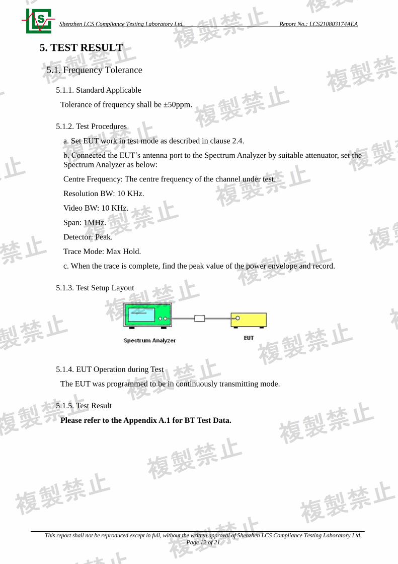
5.1.3. Test Setup Layout
5.1.4. EUT Operation during Test
The EUT was programmed to be in continuously transmitting mode.
5.1.5. Test Result
Please refer to the Appendix A.1 for BT Test Data.
Shenzhen LCS Compliance Testing Laboratory Ltd. Report No.: LCS210803174AEA
This report shall not be reproduced except in full, without the written approval of Shenzhen LCS Compliance Testing Laboratory Ltd.
Page 13 of 21
5.2. Antenna Power
5.2.1. Standard Applicable
Type Limit
Antenna Power 3mW/MHz
Tolerance +20%,-80%
5.2.2. Measuring Instruments
Please refer to section 6 of equipments list in this report.
5.2.2. Test Procedures
a. EUT have transmitted continuous maximum power
b. Antenna Power Error is definition that actual measure antenna power tolerance between +20%
to -80% power range that base on manufacturer declare the conducted power density.
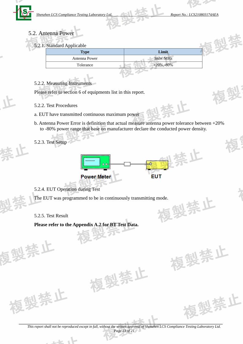
5.2.3. Test Setup
5.2.4. EUT Operation during Test
The EUT was programmed to be in continuously transmitting mode.
5.2.5. Test Result
Please refer to the Appendix A.2 for BT Test Data.
Shenzhen LCS Compliance Testing Laboratory Ltd. Report No.: LCS210803174AEA
This report shall not be reproduced except in full, without the written approval of Shenzhen LCS Compliance Testing Laboratory Ltd.
Page 14 of 21
5.3. Occupied Frequency Bandwidth
5.3.1. Standard Applicable
Permissible value for occupied bandwidth using the FH system, a hybrid system combining DS
and FH systems, or a hybrid system combining FH and OFDM systems shall be 83.5 MHz or
less, while necessary bandwidth (minimum occupied bandwidth sufficient to ensure
information transmission of required quality at a required transmission rate for the system used
under specified conditions for a given emission type) using a system other than any of the
above shall be 26 MHz or less.
5.3.2. Test Procedures
a. Set EUT work in test mode as described in clause 2.4.
b. Connected the EUT’s antenna port to the Spectrum Analyzer by suitable attenuator, set the
Spectrum Analyzer as below:
Centre Frequency: The centre frequency of the channel under test.
Resolution BW: 1MHz.
Video BW: 1MHz.
Span: Wide enough to cover the complete power envelope of the signal of the EUT.
Sweep mode: Continuous sweeping.
Detector: Peak.
Trace Mode: Max Hold.
c. When the trace is complete, measure the occupied bandwidth (99% bandwidth) with
spectrum analyzer’s bandwidth measure function.
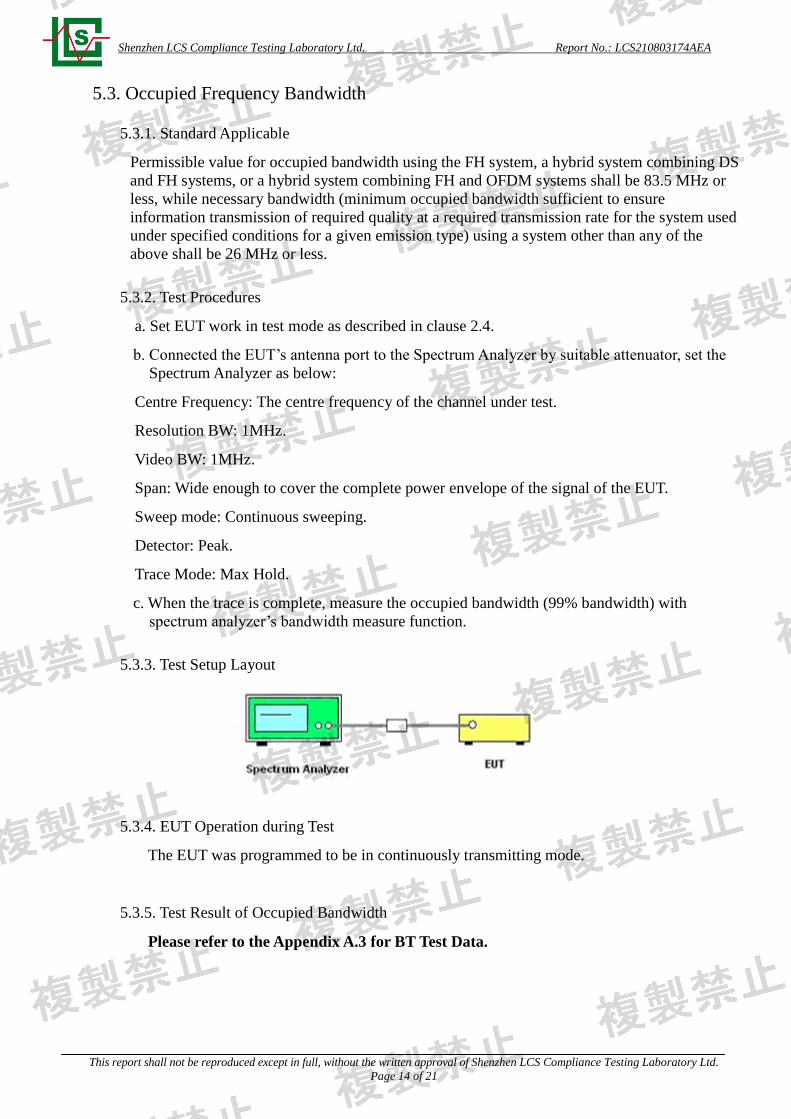
5.3.3. Test Setup Layout
5.3.4. EUT Operation during Test
The EUT was programmed to be in continuously transmitting mode.
5.3.5. Test Result of Occupied Bandwidth
Please refer to the Appendix A.3 for BT Test Data.
Shenzhen LCS Compliance Testing Laboratory Ltd. Report No.: LCS210803174AEA
This report shall not be reproduced except in full, without the written approval of Shenzhen LCS Compliance Testing Laboratory Ltd.
Page 15 of 21
5.4. Spread Bandwidth
5.4.1. Standard Applicable
In spread spectrum systems, spread bandwidth (which refers to a frequency bandwidth with an
upper limit and lower limit such that each of the mean powers radiated above the upper
frequency limit and below the lower frequency limit is equal to 5 % of the total mean power
radiated; this also applies hereafter) shall be 500 kHz or more.
The OFDM system shall have one or more carriers per 1 MHz bandwidth.
5.4.2. Test Procedures
a. Set EUT work in test mode as described in clause 2.4.
b. Connected the EUT’s antenna port to the Spectrum Analyzer by suitable attenuator, set the
Spectrum Analyzer as below:
Centre Frequency: The centre frequency of the channel under test.
Resolution BW: 1MHz.
Video BW: 1MHz.
Span: Wide enough to cover the complete power envelope of the signal of the EUT.
Detector: Peak.
Trace Mode: Max Hold.
c. When the trace is complete, measure the spread bandwidth (90% bandwidth) with spectrum
analyzer’s bandwidth measure function.
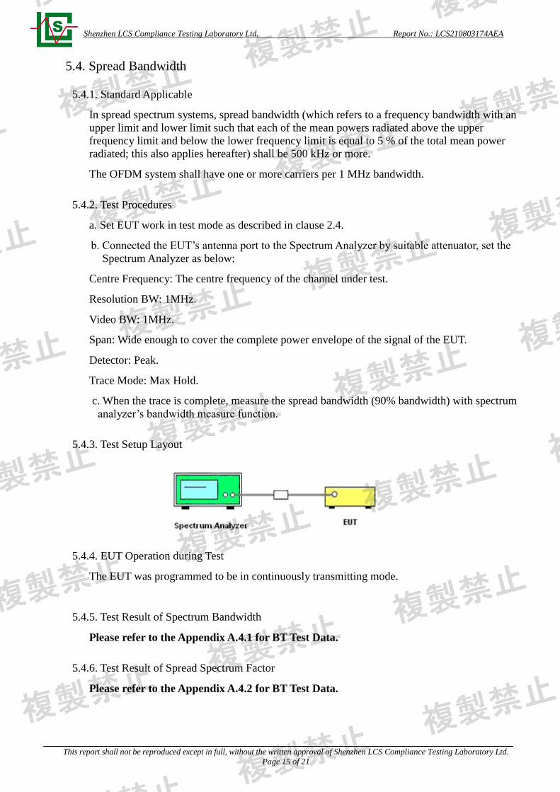
5.4.3. Test Setup Layout
5.4.4. EUT Operation during Test
The EUT was programmed to be in continuously transmitting mode.
5.4.5. Test Result of Spectrum Bandwidth
Please refer to the Appendix A.4.1 for BT Test Data.
5.4.6. Test Result of Spread Spectrum Factor
Please refer to the Appendix A.4.2 for BT Test Data.

Shenzhen LCS Compliance Testing Laboratory Ltd. Report No.: LCS210803174AEA
This report shall not be reproduced except in full, without the written approval of Shenzhen LCS Compliance Testing Laboratory Ltd.
Page 16 of 21
5.5. Transmitter Spurious Emissions (conducted)
5.5.1. Standard Applicable
Permissible mean power of spurious emission of each frequency supplied to a feeder, that is,
mean power of spurious emission in the 1 MHz bandwidth at frequency f other than frequency
band used shall be as follows:
a. 30MHz - 1,000MHz 0.25 μW or less
b. 1,000MHz - 2,387MHz 2.5 μW or less
c. 2,387MHz - 2,400MHz and 2,483.5MHz - 2,496.5MHz 25 μW or less
d. 2,496.5MHz - 12.5GHz 2.5 μW or less
5.5.2. Test Procedures
a. Set EUT work in test mode as described in clause 2.4.
b. Connected the EUT’s antenna port to the Spectrum Analyzer by suitable attenuator, set the
Spectrum Analyzer as below:
Centre Frequency: The centre frequency of the channel under test.
Below 1GHz: RBW/VBW= 100KHz/ 100KHz
Above 1GHz: RBW/VBW= 1MHz / 1MHz.
Detector: Peak.
Trace Mode: Max Hold.
c. All the emissions from 30MHz to 13GHz were measured and record.
5.5.3. Test Setup Layout
5.5.4. EUT Operation during Test
The EUT was programmed to be in continuously transmitting mode.
5.5.5. Test Results
Please refer to the Appendix A.5 for BT Test Data.
Shenzhen LCS Compliance Testing Laboratory Ltd. Report No.: LCS210803174AEA
This report shall not be reproduced except in full, without the written approval of Shenzhen LCS Compliance Testing Laboratory Ltd.
Page 17 of 21
5.6. Secondary Radiated Emissions
5.6.1. Standard Applicable
The limit on secondary emissions radiated from the receiving equipment within which the
function of other radio equipment will not be impaired shall be, in terms of the power of a
dummy antenna circuit that has the same electrical constant as the receiving antenna, 4nW or
less at a frequency below 1 GHz and 20nW or less at a frequency of 1 GHz or higher as
measured using the circuit
5.6.2. Test Procedures
a. Set EUT work in test mode as described in clause 2.4.
b. Connected the EUT’s antenna port to the Spectrum Analyzer by suitable attenuator, set the
Spectrum Analyzer as below:
Resolution BW: 100 KHz for frequency below 1GHz and
1MHz for frequency above 1GHz
Video BW: 100 KHz for frequency below 1GHz and
1MHz for frequency above 1GHz
Detector: Peak.
Trace Mode: Max Hold.
c. All the emissions from 30MHz to 13GHz were measured and record.
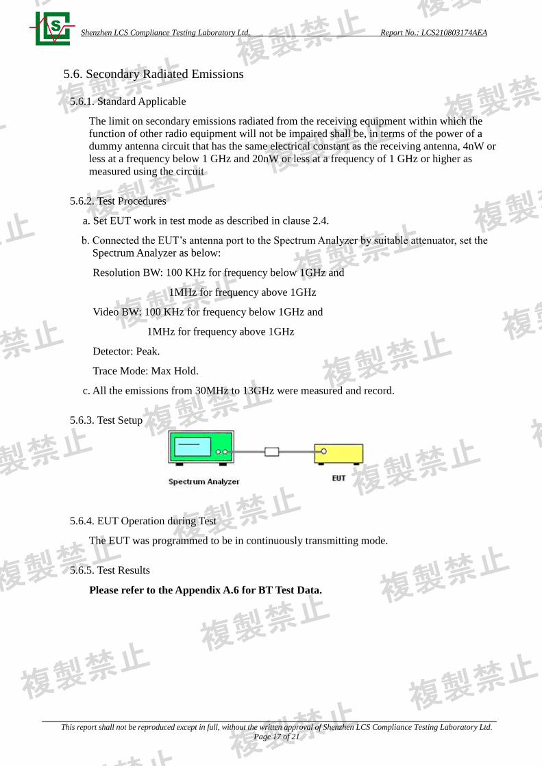
5.6.3. Test Setup
5.6.4. EUT Operation during Test
The EUT was programmed to be in continuously transmitting mode.
5.6.5. Test Results
Please refer to the Appendix A.6 for BT Test Data.
Shenzhen LCS Compliance Testing Laboratory Ltd. Report No.: LCS210803174AEA
This report shall not be reproduced except in full, without the written approval of Shenzhen LCS Compliance Testing Laboratory Ltd.
Page 18 of 21
5.7. Dwell Time
5.7.1. Standard Applicable
Frequency dwell time (time during which radio waves continue to be emitted at a specified
frequency) of a transmitting equipment using the FH system shall be 0.4 seconds or less.
5.7.2. Test Procedures
a. Set EUT work in test mode as described in clause 2.4.
b. Connected the EUT’s antenna port to the Spectrum Analyzer by suitable attenuator, set the
Spectrum Analyzer as below:
Centre Frequency: The centre frequency of the channel under test.
Resolution BW: 1MHz.
Video BW: 1MHz.
Span: Zero MHz
Detector: Peak.
Trace Mode: Max Hold.
c. When the trace is complete, measure the sending time of 1 burst and the duty cycle of 1 burst
cycle.
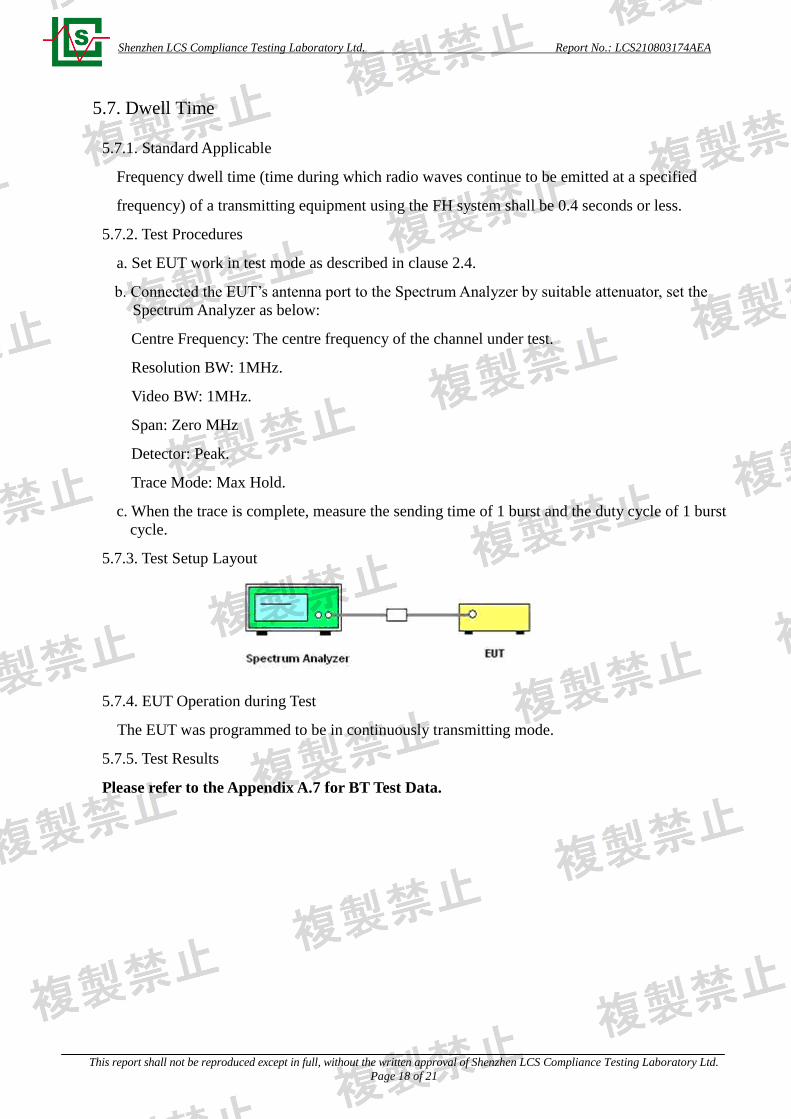
5.7.3. Test Setup Layout
5.7.4. EUT Operation during Test
The EUT was programmed to be in continuously transmitting mode.
5.7.5. Test Results
Please refer to the Appendix A.7 for BT Test Data.
Shenzhen LCS Compliance Testing Laboratory Ltd. Report No.: LCS210803174AEA
This report shall not be reproduced except in full, without the written approval of Shenzhen LCS Compliance Testing Laboratory Ltd.
Page 19 of 21
5.8. Carrier sensing function
5.8.1. Standard Applicable
Item Limits
Carrier Sense Good – EUT stop RF transmission signal after carrier inject to EUT.
(On 22.79+Gr-20*log (f)[dBm] (Gr: dBi; f: MHz) or 100mV/m)
5.8.2. Instruments Setting
The following table is the setting of spectrum analyzer and receiver.
Spectrum Parameter Setting
Attenuation Auto
RB / VB 1 MHz
Span 0 MHz
Sweep Continuous
Detector Peak
Trigger mode Video
5.8.3. Test Procedures
1. SSG adjusted the frequency as same as the EUT transmitted signal and emitted the absence
of modulation from SSG and power level is (On 22.79+Gr-20*log (f) [dBm] (Gr: dBi; f: MHz).
Then turn off the RF signal of SSG.
2. EUT have transmitted the maximum modulation signal and fixed channelize.
3. Setting of SA is following as: RB: 1MHz / VB: 1MHz / SPAN: 50MHz / AT: 10dB /Ref:
0dBm / Sweep time: Auto / Sweep Mode: Continuous sweep / Detect mode: Positive peak.
4. SSG RF Signal On.
5. EUT shall be stop the transmitted any signal and SSG RF Signal Off. Then EUT will be
continuous transmitted signal.
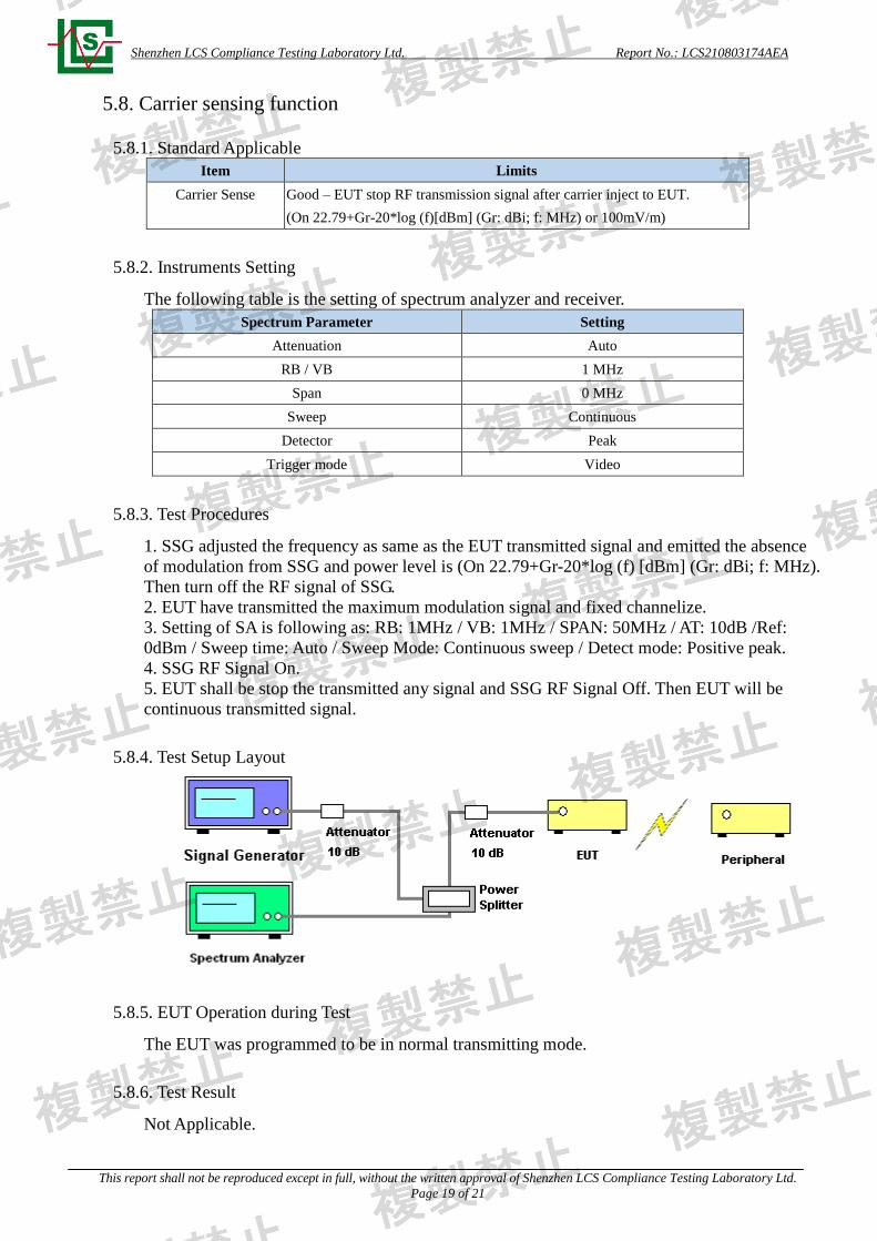
5.8.4. Test Setup Layout
5.8.5. EUT Operation during Test
The EUT was programmed to be in normal transmitting mode.
5.8.6. Test Result
Not Applicable.
Shenzhen LCS Compliance Testing Laboratory Ltd. Report No.: LCS210803174AEA
This report shall not be reproduced except in full, without the written approval of Shenzhen LCS Compliance Testing Laboratory Ltd.
Page 20 of 21
5.9. Interference prevention function
5.9.1. Standard Applicable
Item Limits
Identification code ≧ 48 bits
5.9.2. Measuring ID Code Software
PC with NetTool Setting
MAC IP List MAC Scan
5.9.3. Test Procedures
1. In the case that the EUT has the function of automatically transmitting the identification code:
a. Transmit the predetermined identification codes from EUT. b. Check the transmitted
identification codes with the demodulator.
2. In the case of receiving the identification code: a. Transmit the predetermined identification
codes from the counterpart. b. Check if communication is normal. c. Transmit the other signals
than predetermined ID codes from the counterpart. d. check if the EUT stops the transmission,
or if it displays that identification codes are different from the predetermined ones.
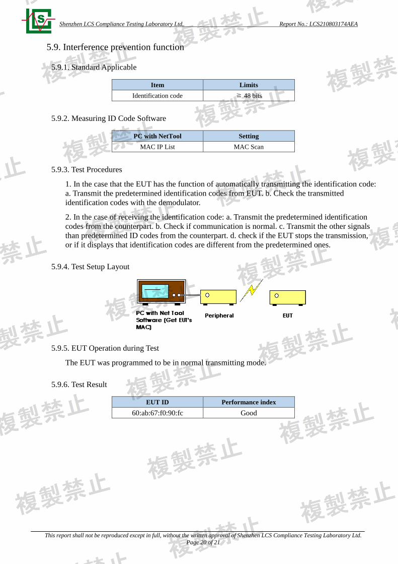
5.9.4. Test Setup Layout
5.9.5. EUT Operation during Test
The EUT was programmed to be in normal transmitting mode.
5.9.6. Test Result
EUT ID Performance index
60:ab:67:f0:90:fc Good
Shenzhen LCS Compliance Testing Laboratory Ltd. Report No.: LCS210803174AEA
This report shall not be reproduced except in full, without the written approval of Shenzhen LCS Compliance Testing Laboratory Ltd.
Page 21 of 21
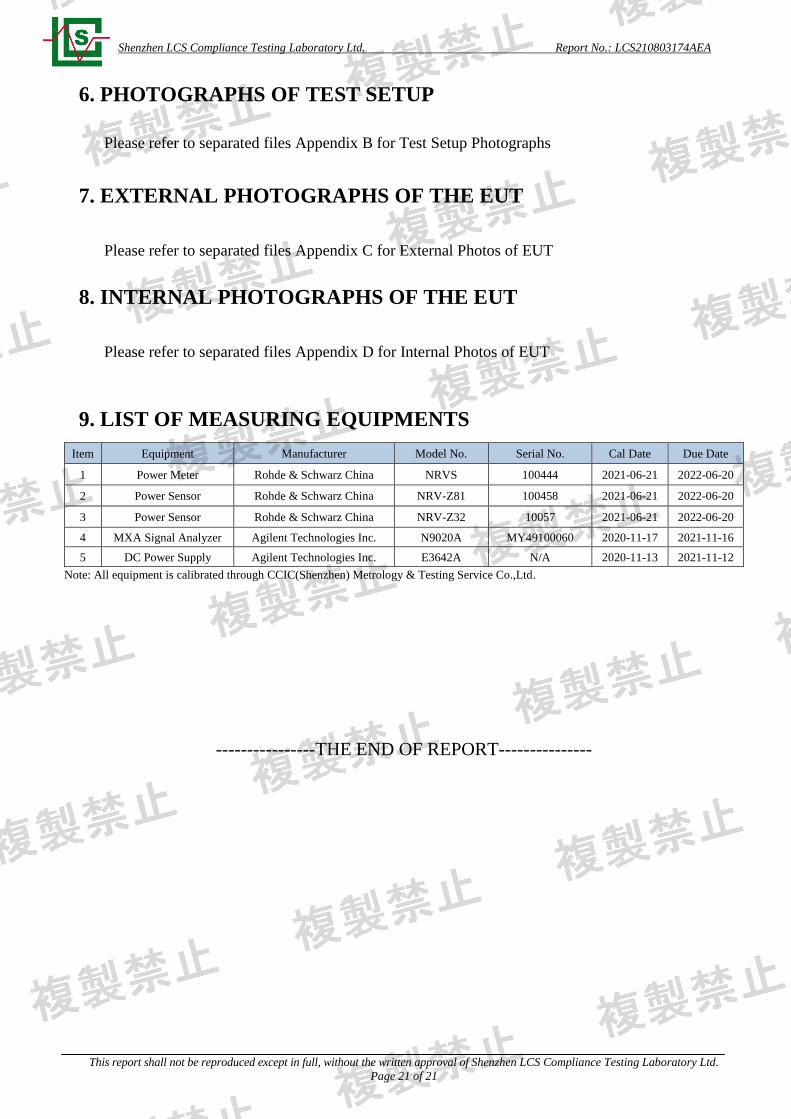
6. PHOTOGRAPHS OF TEST SETUP
Please refer to separated files Appendix B for Test Setup Photographs
7. EXTERNAL PHOTOGRAPHS OF THE EUT
Please refer to separated files Appendix C for External Photos of EUT
8. INTERNAL PHOTOGRAPHS OF THE EUT
Please refer to separated files Appendix D for Internal Photos of EUT
9. LIST OF MEASURING EQUIPMENTS
Item Equipment Manufacturer Model No. Serial No. Cal Date Due Date
1 Power Meter Rohde & Schwarz China NRVS 100444 2021-06-21 2022-06-20
2 Power Sensor Rohde & Schwarz China NRV-Z81 100458 2021-06-21 2022-06-20
3 Power Sensor Rohde & Schwarz China NRV-Z32 10057 2021-06-21 2022-06-20
4 MXA Signal Analyzer Agilent Technologies Inc. N9020A MY49100060 2020-11-17 2021-11-16
5 DC Power Supply Agilent Technologies Inc. E3642A N/A 2020-11-13 2021-11-12
Note: All equipment is calibrated through CCIC(Shenzhen) Metrology & Testing Service Co.,Ltd.
----------------THE END OF REPORT---------------