Radio Propagation Channels - nts.uni-due.dents.uni-due.de/downloads/rpc/radio_pro_ch_1_122.pdf ·...
61
1 Fachgebiet Nachrichtentechnische Systeme NTS UNIVERSITÄT D U I S B U R G E S S E N Prof. Dr.-Ing. Andreas Czylwik Radio Propagation Channels WS 2005/2006 S. 1 Radio Propagation Channels Prof. Dr.-Ing. Andreas Czylwik Fachgebiet Nachrichtentechnische Systeme NTS UNIVERSITÄT D U I S B U R G E S S E N Prof. Dr.-Ing. Andreas Czylwik Radio Propagation Channels WS 2005/2006 S. 2 Radio Propagation Channels Organisational Lecture 2 hours/week Exercise 1 hour/week Transparencies on web site Written examination Department for Communication Systems Diploma and Master Theses Home page: http://nts.uni-duisburg.de
Transcript of Radio Propagation Channels - nts.uni-due.dents.uni-due.de/downloads/rpc/radio_pro_ch_1_122.pdf ·...
1
FachgebietNachrichtentechnische Systeme
N T SUNIVERSITÄT
D U I S B U R GE S S E N
Prof. Dr.-Ing. Andreas Czylwik Radio Propagation Channels WS 2005/2006
S. 1
Radio Propagation Channels
Prof. Dr.-Ing. Andreas Czylwik
FachgebietNachrichtentechnische Systeme
N T SUNIVERSITÄT
D U I S B U R GE S S E N
Prof. Dr.-Ing. Andreas Czylwik Radio Propagation Channels WS 2005/2006
S. 2
Radio Propagation ChannelsOrganisational
Lecture 2 hours/weekExercise 1 hour/weekTransparencies on web siteWritten examination
Department for Communication Systems Diploma and Master ThesesHome page: http://nts.uni-duisburg.de

2
FachgebietNachrichtentechnische Systeme
N T SUNIVERSITÄT
D U I S B U R GE S S E N
Prof. Dr.-Ing. Andreas Czylwik Radio Propagation Channels WS 2005/2006
S. 3
Radio Propagation ChannelsTextbooks
Basic textbooks:T. S. Rappaport: Wireless communications, Prentice HallG. S. Stüber: Principles of mobile communications, KluwerAcademic PublishersW. C. Jakes: Microwave mobile communications, John WileyK. David, T. Benkner: Digitale Mobilfunksysteme, Teubner-Verlag
Advanced textbooks:J. D. Parsons: The mobile radio propagation channel, John WileyJ. Eberspächer, H.-J. Vögel: GSM - Global system for mobilecommunication, Teubner-VerlagH. Holma, A. Toskala: WCDMA for UMTS, John Wiley
FachgebietNachrichtentechnische Systeme
N T SUNIVERSITÄT
D U I S B U R GE S S E N
Prof. Dr.-Ing. Andreas Czylwik Radio Propagation Channels WS 2005/2006
S. 4
Radio Propagation ChannelsContents
1 Introduction2 Wave propagation in mobile communications3 Linear time-variant systems4 Modulation5 Diversity schemes6 Coding7 Multiple access methods8 Cellular systems

3
FachgebietNachrichtentechnische Systeme
N T SUNIVERSITÄT
D U I S B U R GE S S E N
Prof. Dr.-Ing. Andreas Czylwik Radio Propagation Channels WS 2005/2006
S. 5
Radio Propagation Channels1 Introduction
History of radio transmission1888 Heinrich Hertz: Proof of propagation of electromagnetic waves through free space1895 Gugliemo Marconi: First transmission of messages with a radio system over a distance of several km‘s1958-1977 A-Net in Germany1972-1994 B-Net in Germany1986-2000 C-Net (1st generation)1992 D-Net − GSM (2nd generation)1994 E-Net - DCS 1800 (2nd generation)2003 UMTS (3rd generation)2010 4th generation ??
FachgebietNachrichtentechnische Systeme
N T SUNIVERSITÄT
D U I S B U R GE S S E N
Prof. Dr.-Ing. Andreas Czylwik Radio Propagation Channels WS 2005/2006
S. 6
Radio Propagation Channels1 Introduction
Classification of mobile radio systemsType of mobile station
Land radio, marine radio, air radioType of base station
Terrestrical base stations, satellite base stationsType of services
Broadcast (radio/TV), bidirectional communication (mobile phone, wireless local area networks –WLANs)
Type of communication signalsSpeech, pictures, video, data, navigation, locationAnalog/digital
Structure of the networkCellular net, Ad-Hoc net, local net, point-to-point

4
FachgebietNachrichtentechnische Systeme
N T SUNIVERSITÄT
D U I S B U R GE S S E N
Prof. Dr.-Ing. Andreas Czylwik Radio Propagation Channels WS 2005/2006
S. 7
Radio Propagation Channels1 Introduction
Cellular systems in Germany (2nd and 3rd generation)GSM (Global System for Mobile Communications): public mobile phone system with world-wide roamingUMTS (Universal Mobile Telecommunication System): Standard des zukünftigen breitbandigeren öffentlichen Mobilfunksystems
FachgebietNachrichtentechnische Systeme
N T SUNIVERSITÄT
D U I S B U R GE S S E N
Prof. Dr.-Ing. Andreas Czylwik Radio Propagation Channels WS 2005/2006
S. 8
Radio Propagation Channels1 Introduction
Local systems in GermanyDECT (Digital European Cordless Telephone): Cordless standardfor communication short distances (indoor)Bluetooth: cordless standard for small and smallest distances and medium data ratesWLAN IEEE 802.11: Class of wireless local area networks with high data rates
Future systemsUltra-wideband systems for small distances and highest data rates

5
FachgebietNachrichtentechnische Systeme
N T SUNIVERSITÄT
D U I S B U R GE S S E N
Prof. Dr.-Ing. Andreas Czylwik Radio Propagation Channels WS 2005/2006
S. 9
Radio Propagation Channels1 Introduction
Mobile radio systems in GermanySystem / Network GSM: D1/D2 GSM: E1/E2 UMTS, W-CDMA UMTS, TD-CDMA DECT Bluetooth WLAN 802.11a
Frequency range 890-915 / 935-960 MHz
1710-1785 / 1805-1880 MHz
1920-1980 / 2110-2170 MHz
1900-1920 / 2010-2025 MHz
1880-1900 MHz 2402-2485 MHz 5150-5350 / 5470-5725 MHz
Bandwidth 25 MHz (× 2) 75 MHz (× 2) 60 MHz (× 2) (20+15) MHz 20 MHz 83 MHz (ISM) 455 MHz
Duplexing method FDD ∆f = 45 MHz
FDD ∆f = 95 MHz
FDD ∆f = 120 MHz
TDD TDD TDD TDD
Multiple access method FDMA / TDMA FDMA / TDMA FDMA / CDMA CDMA FDMA / TDMA FDMA / FDMA/TDMA
Duplex channels 124 × 8 374 × 8 ca. 60 pro Zelle 10 × 12 79 19 ×
Modulation method GMSK GMSK QPSK QPSK GMSK GMSK OFDM
Channel separation 200 kHz 200 kHz 5 MHz 5 MHz (1,6 MHz) 1728 kHz 1 MHz 20 MHz
Data rate 9,6 kbit/s 9,6 kbit/s 16 ... 384 kbit/s (1,92 Mbit/s)
16 ... 384 kbit/s (1,92 Mbit/s)
32 kbit/s max. 721 kbit/s 6 ... 54 Mbit/s
Mobility vmax = 250 km/h vmax = 130 km/h vmax = 300 km/h vmax = 20 km/h vmax = 30 km/h
MS transmit power 13 ... 33 dBm 4 ... 30 dBm 21 ... 33 dBm 21 ... 33 dBm max. 10 dBm 0 dBm / 20 dBm max. 17 dBm
Range ca. 10 km ca. 8 km ca. 10 km Mainly indoor, up to some km’s
200-300 m 10 m / 100 m einige 100 m
Network operator T-Mobil
D2 Vodafone
E-Plus
VIAG Interkom
5 Network operators Still open Private networks Private networks Private networks
FachgebietNachrichtentechnische Systeme
N T SUNIVERSITÄT
D U I S B U R GE S S E N
Prof. Dr.-Ing. Andreas Czylwik Radio Propagation Channels WS 2005/2006
S. 10
Radio Propagation Channels1 Introduction
Basic problems of mobile radioTime variance of the radio channel (fading, Doppler effect) →Channel coding, diversity schemes
Distance≈λ/2
Rec
eive
d po
wer
[dB
]

6
FachgebietNachrichtentechnische Systeme
N T SUNIVERSITÄT
D U I S B U R GE S S E N
Prof. Dr.-Ing. Andreas Czylwik Radio Propagation Channels WS 2005/2006
S. 11
Radio Propagation Channels1 Introduction
Time dispersion / frequency selectivity→ adapted transmission methods / equalizers
Impulse response:
FachgebietNachrichtentechnische Systeme
N T SUNIVERSITÄT
D U I S B U R GE S S E N
Prof. Dr.-Ing. Andreas Czylwik Radio Propagation Channels WS 2005/2006
S. 12
Radio Propagation Channels1 Introduction
Alternative solution:multicarrier transmission
Transfer function:

7
FachgebietNachrichtentechnische Systeme
N T SUNIVERSITÄT
D U I S B U R GE S S E N
Prof. Dr.-Ing. Andreas Czylwik Radio Propagation Channels WS 2005/2006
S. 13
Radio Propagation Channels1 Introduction
Shared medium → multiple access method necessaryLarge number of users → cellular systems, since bandwidth is limitedSupporting user mobility:
HandoverInternational roaming
Mobile phone is registered at home location register HLR1Connecting in a foreign networkInformation exchange between mobile switching centerMSC2 and MSC1Entries about absence in the home network and connection in the foreign network into HLR1 Entry of the new user in the visitor location register VLR2
FachgebietNachrichtentechnische Systeme
N T SUNIVERSITÄT
D U I S B U R GE S S E N
Prof. Dr.-Ing. Andreas Czylwik Radio Propagation Channels WS 2005/2006
S. 14
Radio Propagation Channels1 Introduction
MSC 1
BS 1
HLR 1
PSTN
MSC 2
BS 2
HLR 2PSTN
VLR 2
PSTN
Fixed Network
BS = base stationMS = mobile stationPSTN = public switched telephone networkMSC = mobile switching centerHLR = home location registerVLR = visitor location register

8
FachgebietNachrichtentechnische Systeme
N T SUNIVERSITÄT
D U I S B U R GE S S E N
Prof. Dr.-Ing. Andreas Czylwik Radio Propagation Channels WS 2005/2006
S. 15
Radio Propagation Channels2 Wave Propagation
Wave propagation
Physical effects
FachgebietNachrichtentechnische Systeme
N T SUNIVERSITÄT
D U I S B U R GE S S E N
Prof. Dr.-Ing. Andreas Czylwik Radio Propagation Channels WS 2005/2006
S. 16
Radio Propagation Channels2 Wave Propagation
Maxwell‘s EquationsAmpere‘s law:
Faraday‘s law:
Notations:E = electrical field strengthH = magnetic field strengthD = electric displacement or electric flux densityB = magnetic induction or magnetic flux densityJ = electric current density
(2.1)t∂
∂+= DJHrot
t∂∂−= BErot (2.2)

9
FachgebietNachrichtentechnische Systeme
N T SUNIVERSITÄT
D U I S B U R GE S S E N
Prof. Dr.-Ing. Andreas Czylwik Radio Propagation Channels WS 2005/2006
S. 17
Radio Propagation Channels2 Wave Propagation
Material properties: ε = permittivityµ = permeabilityκ = conductivity
FachgebietNachrichtentechnische Systeme
N T SUNIVERSITÄT
D U I S B U R GE S S E N
Prof. Dr.-Ing. Andreas Czylwik Radio Propagation Channels WS 2005/2006
S. 18
Radio Propagation Channels2 Wave Propagation
Linear media:ε, µ, κ are independent from field amplitudes
Isotropic media:ε, µ, κ are independent from field directions
Homogeneous media:ε, µ, κ are independent from the position
Dispersion-free media:ε, µ, κ are independent from frequency
Loss-free media:κ = 0 and ε, µ are real

10
FachgebietNachrichtentechnische Systeme
N T SUNIVERSITÄT
D U I S B U R GE S S E N
Prof. Dr.-Ing. Andreas Czylwik Radio Propagation Channels WS 2005/2006
S. 19
Radio Propagation Channels2 Wave Propagation
Material equations for lineare homogeneous isotropic lossy dielectric media:
Notations:κ = conductivityε0 = permittivity of vacuumεr = relative permittivityµ0 = magnetic permeability of vacuum
= diffraction index
HBED
EJ
0
r0µ
εεκ
=== (2.3)
(2.4)(2.5)
rε=n
FachgebietNachrichtentechnische Systeme
N T SUNIVERSITÄT
D U I S B U R GE S S E N
Prof. Dr.-Ing. Andreas Czylwik Radio Propagation Channels WS 2005/2006
S. 20
Radio Propagation Channels2 Wave Propagation
Wave equationInserting material equations:
Introducing complex amplitudes:
(2.6)t∂
∂+= EEH r0rot εεκ
t∂∂−= HE 0rot µ (2.7)
eRe)(,eRe)( jj tt tt ωω ⋅=⋅= HHEE (2.8)
HEEH
0
r0jrot
)j(rotωµ
εωεκ−=
+= (2.9)(2.10)
11
FachgebietNachrichtentechnische Systeme
N T SUNIVERSITÄT
D U I S B U R GE S S E N
Prof. Dr.-Ing. Andreas Czylwik Radio Propagation Channels WS 2005/2006
S. 21
Radio Propagation Channels2 Wave Propagation
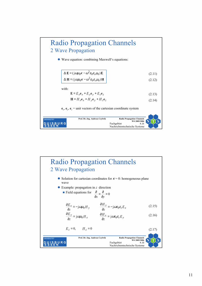
Wave equation: combining Maxwell‘s equations:
with:
ex, ey, ez = unit vectors of the cartesian coordinate system
(2.11)
(2.12)
(2.13)
HH
EE
)j(
)j(
0r02
0
0r02
0
µεεωκωµ
µεεωκωµ
−=∆
−=∆
(2.14)zzyyxx
zzyyxx
HHH
EEE
eeeH
eeeE
++=
++=
FachgebietNachrichtentechnische Systeme
N T SUNIVERSITÄT
D U I S B U R GE S S E N
Prof. Dr.-Ing. Andreas Czylwik Radio Propagation Channels WS 2005/2006
S. 22
Radio Propagation Channels2 Wave Propagation
Solution for cartesian coordinates for κ = 0: homogeneous planewaveExample: propagation in z direction
Field equations for
(2.15)
(2.16)
(2.17)0,0
jj
jj
r00
r00
==
=∂
∂=∂
∂
−=∂
∂−=
∂∂
zz
yx
xy
xy
yx
HE
Ez
HHz
E
Ez
HH
zE
εωεωµ
εωεωµ
0=∂∂=
∂∂
yx

12
FachgebietNachrichtentechnische Systeme
N T SUNIVERSITÄT
D U I S B U R GE S S E N
Prof. Dr.-Ing. Andreas Czylwik Radio Propagation Channels WS 2005/2006
S. 23
Radio Propagation Channels2 Wave Propagation
Independent wave equations per component:
with k2 = ω2ε0εrµ0 k = 2π/λn = ω n/c0
Solution for the electrical field:
(2.18)
(2.19)
(2.20)
0
0
22
2
22
2
=+∂
∂
=+∂
∂
yy
xx
Ekz
E
EkzE
kzy
kzyy
kzx
kzxx
eEeEE
eEeEEjj
jj
+−
−+
+−
−+
+=
+= (2.21)
(2.22)
FachgebietNachrichtentechnische Systeme
N T SUNIVERSITÄT
D U I S B U R GE S S E N
Prof. Dr.-Ing. Andreas Czylwik Radio Propagation Channels WS 2005/2006
S. 24
Radio Propagation Channels2 Wave Propagation
Solution for the magnetic field:
with the characteristic impedance of the dielectric:
Characteristic impedance of vacuum:
(2.23)
(2.24)
(2.25)
( )( )kz
ykz
yx
kzx
kzxy
eEeEZ
H
eEeEZ
H
jj
D
jj
D1
1
+−
−+
+−
−+
−−=
−=
(2.26)
nZZ 0
r0
0D ==
εεµ
−
−
+
+
−
−
+
+ =−=−==y
x
x
y
y
x
y
xHE
HE
HE
HEZD
Ω≈Ω== 377π1200
00 ε
µZ(2.27)

13
FachgebietNachrichtentechnische Systeme
N T SUNIVERSITÄT
D U I S B U R GE S S E N
Prof. Dr.-Ing. Andreas Czylwik Radio Propagation Channels WS 2005/2006
S. 25
Radio Propagation Channels2 Wave Propagation
PolarizationGeneral approach for a plane wave propagating in z-direction:
Phase difference of waves: ∆ϕ = ϕy − ϕx
∆ϕ = 0 (oder ∆ϕ = π) ⇒ linearly polarized wave∆ϕ = ±π/2 und ⇒ circularly polarized wave∆ϕ = ϕ0 ⇒ elliptically polarized wave
(2.28)(2.29)
(2.30)
(2.31)
kzyyyxxx
kzyyxx
kzyyxx
tEtE
tEtEt
EE
j
j
j
e])cos(ˆ)cos(ˆ[
e])()([)(
e][
−
−
−
+++=
+=
+=
ee
eeE
eeE
ϕωϕω
yx EE ˆˆ =
FachgebietNachrichtentechnische Systeme
N T SUNIVERSITÄT
D U I S B U R GE S S E N
Prof. Dr.-Ing. Andreas Czylwik Radio Propagation Channels WS 2005/2006
S. 26
Radio Propagation Channels2 Wave PropagationElectrical field
∆ϕ = 0 ∆ϕ = π/3 ∆ϕ = π/2 and
xExE−
yE−
yEyE
xE xExE−
yE−
yEyE
xE xExE−
yE−
yE
yE
xE
yx EE ˆˆ =

14
FachgebietNachrichtentechnische Systeme
N T SUNIVERSITÄT
D U I S B U R GE S S E N
Prof. Dr.-Ing. Andreas Czylwik Radio Propagation Channels WS 2005/2006
S. 27
Radio Propagation Channels2 Wave Propagation
Planar wave in an arbitrary directionLocation vector: r = xex + yey + zez
Vector wave number: k = kxex + kyey + kzez
Relation to scalar wave numbers:
Generalized planar harmonic wave:
with e1⋅k = 0, e2⋅k = 0, e1⋅e2 = 0
2222zyx kkkkk ++=⇔=⋅kk
(2.32)(2.33)
(2.34)
(2.35)
kr
kr
kr
ee
eeE
eeE
j222111
j2211
j2211
e])cos(ˆ)cos(ˆ[
e])()([)(
e][
−
−
−
+++=
+=
+=
ϕωϕω tEtE
tEtEt
EE
(2.36)(2.37)
(2.38)
FachgebietNachrichtentechnische Systeme
N T SUNIVERSITÄT
D U I S B U R GE S S E N
Prof. Dr.-Ing. Andreas Czylwik Radio Propagation Channels WS 2005/2006
S. 28
Radio Propagation Channels2 Wave Propagation
Reflection and diffraction at the boundary surface z = 0 (x-y-plane) between two lossless dielectrica
⊥eE
||eE⊥rE
||rE
||gE
⊥gE
x
y z
ek
rk
gk
eα rα
gα)( 12
1nn
n>

15
FachgebietNachrichtentechnische Systeme
N T SUNIVERSITÄT
D U I S B U R GE S S E N
Prof. Dr.-Ing. Andreas Czylwik Radio Propagation Channels WS 2005/2006
S. 29
Radio Propagation Channels2 Wave Propagation
Incident wave:
Reflected wave:
Refracted wave:
Continuity conditions at the boundary surface: Et,1 = Et,2,Ht,1 = Ht,2
Law of reflection: αe = αr
Law of refraction: n1 sin αe = n2 sin αg
rkrk eeEEE ee jee||e||e
je||ee e][e][ −
⊥⊥−
⊥ +=+= EE
rkrk eeEEE rr jrr||r||r
jr||rr e][e][ −
⊥⊥−
⊥ +=+= EE
rkrk eeEEE gg jgg||g||g
jg||gg e][e][ −
⊥⊥−
⊥ +=+= EE
(2.39)
(2.40)
(2.41)
(2.42)
(2.43)
FachgebietNachrichtentechnische Systeme
N T SUNIVERSITÄT
D U I S B U R GE S S E N
Prof. Dr.-Ing. Andreas Czylwik Radio Propagation Channels WS 2005/2006
S. 30
Radio Propagation Channels2 Wave Propagation
Reflection and transmission factors (Fresnel equations):
(2.44)
(2.45)
(2.46)
(2.47)
e22
122e1
e22
122e1
||e
||r||
sincos
sincos
αα
αα
nnn
nnnEE
r−+
−−==
e22
1221e
22
e22
1221e
22
e
r
sincos
sincos
αα
αα
nnnn
nnnnEEr
−+
−−−==
⊥
⊥⊥
e22
122e1
e1
||e
||g||
sincos
cos2
ααα
nnn
nEE
t−+
==
e22
1221e
22
e21
e
g
sincos
cos2
ααα
nnnn
nnEE
t−+
−==⊥
⊥⊥

16
FachgebietNachrichtentechnische Systeme
N T SUNIVERSITÄT
D U I S B U R GE S S E N
Prof. Dr.-Ing. Andreas Czylwik Radio Propagation Channels WS 2005/2006
S. 31
Radio Propagation Channels2 Wave Propagation
Can reflection factors become zero?
vanishes only if no boundary surface exists.
αB = Brewster angle
(2.48)
21e22
122e
221
e22
122e1||
sincos
0sincos0
nnnnn
nnnr
=⇒−=
=−−⇒=
αα
αα
22
21
22
B2
e22
122
21e
242
e22
1221e
22
sin
)sin(cos
0sincos0
nnn
nnnn
nnnnr
+=
−=
=−−⇒=⊥
α
αα
αα
||r
FachgebietNachrichtentechnische Systeme
N T SUNIVERSITÄT
D U I S B U R GE S S E N
Prof. Dr.-Ing. Andreas Czylwik Radio Propagation Channels WS 2005/2006
S. 32
Radio Propagation Channels2 Wave Propagation
Total reflectionFor the roots become imaginary.
Total reflection if:
(only possible if n1 > n2)
(2.49)
0sin e22
122 <− αnn
1|||||| ==⇒= ∗∗ z
zrzzr
1
2esin
nn>α

17
FachgebietNachrichtentechnische Systeme
N T SUNIVERSITÄT
D U I S B U R GE S S E N
Prof. Dr.-Ing. Andreas Czylwik Radio Propagation Channels WS 2005/2006
S. 33
Radio Propagation Channels2 Wave Propagation
Reflexion factors for different angles of incidence: αe = 0 αe = π/2n1 > n2
n1 < n2
||r ⊥r
||r ⊥r
1
1
11
1−1
−1
−1
−1 −1
21
21nnnn
+−
21
21nnnn
+−
21
21nnnn
+−
21
21nnnn
+−
ReRe
ReRe
Im
Im
Im
Im
FachgebietNachrichtentechnische Systeme
N T SUNIVERSITÄT
D U I S B U R GE S S E N
Prof. Dr.-Ing. Andreas Czylwik Radio Propagation Channels WS 2005/2006
S. 34
Radio Propagation Channels2 Wave Propagation
Reflection factors for a radio channel with reflection at a lossy dielectric medium
Horizontal polarization:
Vertical polarization:
Limit for very flat incidence αe → π/2:
(2.50)
(2.51)
e2
0re
e2
0re
he,
hr,h
sin)/j(cos
sin)/j(cos
αωεκεα
αωεκεα
−−+
−−−==
EE
r
e2
0re0r
e2
0re0r
ve,
vr,v
sin)/j(cos)/j(
sin)/j(cos)/j(
αωεκεαωεκε
αωεκεαωεκε
−−+−
−−−−==
EE
r
1limlim h2/π
v2/π ee
−==→→
rrαα
(2.52)

18
FachgebietNachrichtentechnische Systeme
N T SUNIVERSITÄT
D U I S B U R GE S S E N
Prof. Dr.-Ing. Andreas Czylwik Radio Propagation Channels WS 2005/2006
S. 35
Radio Propagation Channels2 Wave Propagation
AntennasHertz‘ dipole in free Space
Point-shaped oscillating charges+q and −q
Distance ∆l << λ/4∆l ⋅ I = dipole momentField is symmetric withrespect to rotation
Description in polar coordinates
y
x
z
ϕ
ϑ
r
Er
Eϑ
Hϕ
FachgebietNachrichtentechnische Systeme
N T SUNIVERSITÄT
D U I S B U R GE S S E N
Prof. Dr.-Ing. Andreas Czylwik Radio Propagation Channels WS 2005/2006
S. 36
Radio Propagation Channels2 Wave Propagation
Complex amplitude of the magnetic field:
Complex amplitude of the electric field:
ϕϕλϑ
λeHH ⋅⋅
+⋅⋅∆== − rkerr
lI jπ2j
1sin2
j
rrk
rkr
errr
lIZ
errr
lIZ
e
eEEE
⋅⋅
+⋅⋅∆+
⋅⋅
++⋅⋅∆=+=
−
−
j2
0
j2
0
π2jπ2jcos2
2j
π2jπ2j1sin
2j
λλϑλ
λλϑλ ϑϑ
(2.53)
(2.54)
19
FachgebietNachrichtentechnische Systeme
N T SUNIVERSITÄT
D U I S B U R GE S S E N
Prof. Dr.-Ing. Andreas Czylwik Radio Propagation Channels WS 2005/2006
S. 37
Radio Propagation Channels2 Wave Propagation
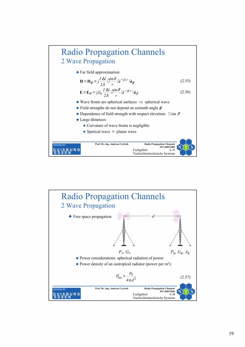
Far field approximation:
Wave fronts are spherical surfaces ⇒ spherical waveField strengths do not depend on azimuth angle ϕDependence of field strength with respect elevation: ∼ sin ϑLarge distances:
Curvature of wave fronts is negligibleSperical wave ≈ planar wave
ϑϑ
ϕϕ
ϑλ
ϑλ
eEE
eHH
⋅⋅⋅∆==
⋅⋅⋅∆==
−
−
rk
rk
er
lIZ
er
lI
j0
j
sin2
j
sin2
j (2.55)
(2.56)
FachgebietNachrichtentechnische Systeme
N T SUNIVERSITÄT
D U I S B U R GE S S E N
Prof. Dr.-Ing. Andreas Czylwik Radio Propagation Channels WS 2005/2006
S. 38
Free space propagation
Power considerations: spherical radiation of powerPower density of an isotropical radiator (power per m2):
Radio Propagation Channels2 Wave Propagation
2T
isoπ4 dPP =′ (2.57)

20
FachgebietNachrichtentechnische Systeme
N T SUNIVERSITÄT
D U I S B U R GE S S E N
Prof. Dr.-Ing. Andreas Czylwik Radio Propagation Channels WS 2005/2006
S. 39
Radio Propagation Channels2 Wave Propagation
Power density of a transmit antenna (power per m2):
Available power at the receive antenna:
Power transfer factor:
2TT
Tπ4 d
GPP ⋅=′
π4π4π4R
2
2TT
R2TT
RG
dGPA
dGPP ⋅⋅⋅=⋅⋅= λ
2
RT
2
RTT
Rπ4π4
⋅⋅=
⋅⋅=fd
cGGd
GGPP λ
(2.58)
(2.59)
(2.60)
FachgebietNachrichtentechnische Systeme
N T SUNIVERSITÄT
D U I S B U R GE S S E N
Prof. Dr.-Ing. Andreas Czylwik Radio Propagation Channels WS 2005/2006
S. 40
Radio Propagation Channels2 Wave Propagation
Antenna gain: gain factor of the power density relative to the (not realizable) isotropic radiatorRelation between antenna gain and effective antenna surface:
Notations:PR = received powerPT = transmit powerGR = gain of the receive antennaGT = gain of the transmit antennaAR = effective surface of the receive antennaλ = carrier wavelength, f = carrier frequency
GA ⋅=π4
2eff
λ(2.61)

21
FachgebietNachrichtentechnische Systeme
N T SUNIVERSITÄT
D U I S B U R GE S S E N
Prof. Dr.-Ing. Andreas Czylwik Radio Propagation Channels WS 2005/2006
S. 41
Radio Propagation Channels2 Wave Propagation
Path loss:
Free space attenuation:
RT
2
RTT
RP
log10log10
π4log10log10
GGL
dGG
PPL
F −−=
⋅⋅−=
−= λ
+
+=
=
=
kmlog20
GHzlog20dB44,92
π4log20π4log20F
dfc
fddLλ
(2.62)
(2.63)
FachgebietNachrichtentechnische Systeme
N T SUNIVERSITÄT
D U I S B U R GE S S E N
Prof. Dr.-Ing. Andreas Czylwik Radio Propagation Channels WS 2005/2006
S. 42
Radio Propagation Channels2 Wave Propagation
Relation between power density (magnitude of the Pointing vector) and the electric field strength:
with Z0 = characteristic impedance of free space: Z0 = 120 π Ω≈ 377 ΩRadiated field strength of the transmit antenna:
0
2eff,0
ZE
P =′
dGP
EdGPE
P TTeff,02
TT
0
2eff,0
T30
π4Z⋅⋅
=⇒⋅==′
(2.64)
(2.65)

22
FachgebietNachrichtentechnische Systeme
N T SUNIVERSITÄT
D U I S B U R GE S S E N
Prof. Dr.-Ing. Andreas Czylwik Radio Propagation Channels WS 2005/2006
S. 43
Radio Propagation Channels2 Wave Propagation
Received power for a given field strength E0,eff :
Formulas for free space transmission can be directly used for point-to-point transmissions (fixed radio systems)
Reciprocity: the antenna gain is the same for transmit and receive usage
Ω
⋅=⋅⋅
Ω=⋅=
120π2π4π120R
2eff,0R
22eff,0
R0
2eff,0
RGEGE
AZ
EP
λλ (2.66)
FachgebietNachrichtentechnische Systeme
N T SUNIVERSITÄT
D U I S B U R GE S S E N
Prof. Dr.-Ing. Andreas Czylwik Radio Propagation Channels WS 2005/2006
S. 44
Radio Propagation Channels2 Wave Propagation
DiffractionWave propagation according to geometrical optics ifλ << object sizeGeometrical optics: tightlight-shadow borderDifference with respect to optics: field strength in the shadow of buildings and other obstacles is not negigibleHuygens‘ principle
23
FachgebietNachrichtentechnische Systeme
N T SUNIVERSITÄT
D U I S B U R GE S S E N
Prof. Dr.-Ing. Andreas Czylwik Radio Propagation Channels WS 2005/2006
S. 45
Radio Propagation Channels2 Wave Propagation
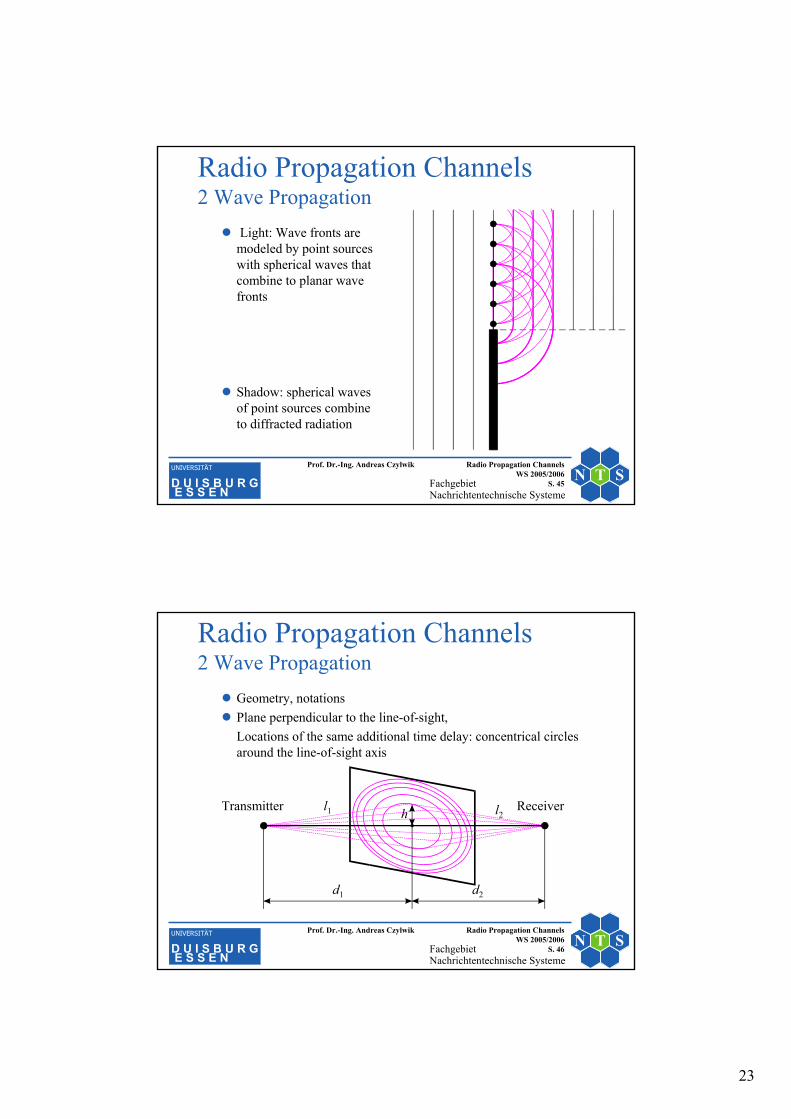
Light: Wave fronts are modeled by point sources with spherical waves that combine to planar wave fronts
Shadow: spherical waves of point sources combine to diffracted radiation
FachgebietNachrichtentechnische Systeme
N T SUNIVERSITÄT
D U I S B U R GE S S E N
Prof. Dr.-Ing. Andreas Czylwik Radio Propagation Channels WS 2005/2006
S. 46
Geometry, notationsPlane perpendicular to the line-of-sight,Locations of the same additional time delay: concentrical circles around the line-of-sight axis
Radio Propagation Channels2 Wave Propagation
d1
h
d2
Transmitter Receiverl1 l2

24
FachgebietNachrichtentechnische Systeme
N T SUNIVERSITÄT
D U I S B U R GE S S E N
Prof. Dr.-Ing. Andreas Czylwik Radio Propagation Channels WS 2005/2006
S. 47
Radio Propagation Channels2 Wave Propagation
Additional path length:
Corresponding phase difference
with the Fresnel-Kirchhoff diffraction parameter:
hdddd
h
ddhdhdddllx
>>
+≈
−−+++=−−+=∆
2121
221
222
2212121
,for112 (2.67)
2
21
2
2π11
2π2π2 v
ddhx ⋅=
+⋅=∆=∆
λλϕ
+⋅=21
112dd
hvλ
(2.69)
(2.68)
FachgebietNachrichtentechnische Systeme
N T SUNIVERSITÄT
D U I S B U R GE S S E N
Prof. Dr.-Ing. Andreas Czylwik Radio Propagation Channels WS 2005/2006
S. 48
Radio Propagation Channels2 Wave Propagation
Definition of Fresnel zones: path difference
Radii of Fresnel zones depend on the location between the antennas:
Numerical example: f = 1 GHz, d1 = d2 = 1 km
(2.70)
21
21dd
ddnrh n +⋅⋅== λ
2λ⋅=∆ nxn
(2.71)
m2,122
11 =⋅= dr λ
(2.72)nvn ⋅= 2
(2.73)

25
FachgebietNachrichtentechnische Systeme
N T SUNIVERSITÄT
D U I S B U R GE S S E N
Prof. Dr.-Ing. Andreas Czylwik Radio Propagation Channels WS 2005/2006
S. 49
Radio Propagation Channels2 Wave Propagation
Fresnel zones: Sum of distances with respect to two points is constant ⇒ ellipseLocations with the same phase difference lie on the Fresnel ellipsoid:
Almost unaffected transmission if no obstacle is within the firstFresnel zone
FachgebietNachrichtentechnische Systeme
N T SUNIVERSITÄT
D U I S B U R GE S S E N
Prof. Dr.-Ing. Andreas Czylwik Radio Propagation Channels WS 2005/2006
S. 50
Radio Propagation Channels2 Wave Propagation
Model for an obstacle: ideal absorbing half-plane
h, v > 0 ⇒ shadowingh, v < 0 ⇒ no shadowing
d1
h
d2Transmitter Receiver

26
FachgebietNachrichtentechnische Systeme
N T SUNIVERSITÄT
D U I S B U R GE S S E N
Prof. Dr.-Ing. Andreas Czylwik Radio Propagation Channels WS 2005/2006
S. 51
Radio Propagation Channels2 Wave Propagation
Transmission factornormalized to free-space transmission:
∫∞ −+=v
t tEE de
2j1 2
2j
0
π(2.74)
FachgebietNachrichtentechnische Systeme
N T SUNIVERSITÄT
D U I S B U R GE S S E N
Prof. Dr.-Ing. Andreas Czylwik Radio Propagation Channels WS 2005/2006
S. 52
Radio Propagation Channels2 Wave Propagation
Diffraction problems in real propagation scenarios are more complex:
Finite dimensions of obstaclesMultiple diffractionsBuildings are not ideal absorbersFinite dimension of the absorbers in propagation directionRough surfacesPropagation over a long distance: earth curvature is not negligible
Solution: empirical formulas for the attenuation in specific propagation scenarios

27
FachgebietNachrichtentechnische Systeme
N T SUNIVERSITÄT
D U I S B U R GE S S E N
Prof. Dr.-Ing. Andreas Czylwik Radio Propagation Channels WS 2005/2006
S. 53
Radio Propagation Channels2 Wave Propagation
Single and multipath propagation, overviewDoppler effectFast fadingTime dispersionPropagation scenariosSpatial correlation
FachgebietNachrichtentechnische Systeme
N T SUNIVERSITÄT
D U I S B U R GE S S E N
Prof. Dr.-Ing. Andreas Czylwik Radio Propagation Channels WS 2005/2006
S. 54
Radio Propagation Channels2 Wave Propagation
Single path propagationAssumptions: distance x << d , direct line-of-sight, no obstacles, plane waveReceived signal:
with the wave number k = 2π / λ
)cos(j0 10e)( xktAtr θω −= (2.75)

28
FachgebietNachrichtentechnische Systeme
N T SUNIVERSITÄT
D U I S B U R GE S S E N
Prof. Dr.-Ing. Andreas Czylwik Radio Propagation Channels WS 2005/2006
S. 55
Radio Propagation Channels2 Wave Propagation
Received signal:
With velocity v ⇒ x = v ⋅ t andDoppler frequency
Numerical example: f0 = 1 GHz, v = 30 m/s = 108 km/h, θ1= 0° ⇒ f D = 100 HzAmplitude amplitude of the received signals:⇒ no fast fading effect
t
tvt
A
Atr)(j
0
)cos2(j0
D0
10
e
e)(ωω
θλπω
−
−
=
=
konst.)( 0 == Atr
10
1 coscos2
θθλπ
ωcfvvf D
D ===
(2.76)
(2.77)
(2.78)
FachgebietNachrichtentechnische Systeme
N T SUNIVERSITÄT
D U I S B U R GE S S E N
Prof. Dr.-Ing. Andreas Czylwik Radio Propagation Channels WS 2005/2006
S. 56
Radio Propagation Channels2 Wave Propagation
Two-path propagationReceived signal:
)cos(j2
)cos(j1 2010 ee)( xktxkt AAtr θωθω −− +=
[ ][ ]
)()cossin()cossin(
)coscos()coscos()(2
2211
22211
2
xfxkAxkA
xkAxkAtr
=++
+=
θθ
θθ
(2.79)
(2.80)

29
FachgebietNachrichtentechnische Systeme
N T SUNIVERSITÄT
D U I S B U R GE S S E N
Prof. Dr.-Ing. Andreas Czylwik Radio Propagation Channels WS 2005/2006
S. 57
Radio Propagation Channels2 Wave Propagation
Special case: A1 = A2= A0
. . .
)cos(j0
)cos(j0 2010 ee)( xktxkt AAtr θωθω −− +=
2)cos(coscos2)( 21
0θθ −= xkAxr
(2.81)
(2.82)
FachgebietNachrichtentechnische Systeme
N T SUNIVERSITÄT
D U I S B U R GE S S E N
Prof. Dr.-Ing. Andreas Czylwik Radio Propagation Channels WS 2005/2006
S. 58
Radio Propagation Channels2 Wave Propagation
Example: θ1 = 0, θ2 = π
)2cos(2)( 0 λπ xAxr =
0.0
0.2
0.4
0.6
0.8
1.0
0.00 0.25 0.50 0.75 1.00 1.25 1.50 x/λ
02)(
Axr
(2.83)

30
FachgebietNachrichtentechnische Systeme
N T SUNIVERSITÄT
D U I S B U R GE S S E N
Prof. Dr.-Ing. Andreas Czylwik Radio Propagation Channels WS 2005/2006
S. 59
Radio Propagation Channels2 Wave Propagation
Example: ground reflection, earth curvature neglectedSmall angle of incidence ⇒
Contributions fron two paths:
1hv −≅≅ rr
l1
l2
hT
hR
d
ϕ∆−⋅−⋅+≅+= j0021 )1( eEEEEE (2.84)
FachgebietNachrichtentechnische Systeme
N T SUNIVERSITÄT
D U I S B U R GE S S E N
Prof. Dr.-Ing. Andreas Czylwik Radio Propagation Channels WS 2005/2006
S. 60
Radio Propagation Channels2 Wave Propagation
Magnitude of the complex amplitude:
Phase difference:
)sinjcos1(0 ϕϕ ∆+∆−= EE (2.85)
2sin2
2sin22cos22
sin)cos1(
0
200
220
ϕ
ϕϕ
ϕϕ
∆⋅⋅=
∆⋅=∆−=
∆+∆−=
E
EE
EE
)(21212 lllklk −=⋅−⋅=∆
λπϕ
2RT
22
2RT
21 )(and)(with hhdlhhdl ++=−+=
(2.86)
(2.87)
(2.88)
(2.89)
(2.90)

31
FachgebietNachrichtentechnische Systeme
N T SUNIVERSITÄT
D U I S B U R GE S S E N
Prof. Dr.-Ing. Andreas Czylwik Radio Propagation Channels WS 2005/2006
S. 61
Radio Propagation Channels2 Wave Propagation
Phase difference:
(2.91)
dhh
dhhd
dhh
dhhd
dhh
dhhd
hhdhhd
λλ
λ
λ
λϕ
RT2
RT
2
2RT
2
2RT
2
2RT
2
2RT
2RT
22RT
2
π4222π2
2)(1
2)(1π2
)(1)(1π2
)()(π2
=⋅⋅⋅=
−−−++⋅⋅≈
−+−++⋅⋅=
−+−++=∆
(2.92)
(2.93)
(2.94)
FachgebietNachrichtentechnische Systeme
N T SUNIVERSITÄT
D U I S B U R GE S S E N
Prof. Dr.-Ing. Andreas Czylwik Radio Propagation Channels WS 2005/2006
S. 62
Radio Propagation Channels2 Wave Propagation
Transmission factor because of ground reflection:
Attenuation because of ground reflection:
Example: hT = 100 λ, hR = 5 λ, λ = 0,3 m
(2.95)
(2.96)
(2.97)
dhh
EE
λRT
0
π2sin2 ⋅=
λλ
λ
RTRT
RT
0ground
forπ22lg20
π2sin2lg20lg20
hhddhh
dhh
EE
a
>>⋅−≈
⋅−=−=−
m150500RT ==>>⇒ λλhhd

32
FachgebietNachrichtentechnische Systeme
N T SUNIVERSITÄT
D U I S B U R GE S S E N
Prof. Dr.-Ing. Andreas Czylwik Radio Propagation Channels WS 2005/2006
S. 63
Radio Propagation Channels2 Wave Propagation
Additional attenuation because of ground reflection: −aground
-50
-40
-30
-20
-10
0
10
0 1 2 3 4
RTlg
hhd
⋅⋅ λ
aground[dB]
(2.97)
FachgebietNachrichtentechnische Systeme
N T SUNIVERSITÄT
D U I S B U R GE S S E N
Prof. Dr.-Ing. Andreas Czylwik Radio Propagation Channels WS 2005/2006
S. 64
Radio Propagation Channels2 Wave Propagation
Total transmission factor including free-space attenuation:
Approximation for long distances
(2.98)
(2.99)
λRThhd >>
dhh
dGG
PP
λλ RT2
2
RTT
R π2sin4π4
⋅⋅
⋅⋅=
2
2RT
RTT
R
⋅⋅=
dhhGG
PP

33
FachgebietNachrichtentechnische Systeme
N T SUNIVERSITÄT
D U I S B U R GE S S E N
Prof. Dr.-Ing. Andreas Czylwik Radio Propagation Channels WS 2005/2006
S. 65
Radio Propagation Channels2 Wave Propagation
n-path propagation for unmodulated carrier signalsComplex amplitude of the received signal:
Squared magnitude (~ received power):
AR and AI are random variablesApproximation: large number of statistically independent propagation paths⇒ central limit theorem is applicable
(2.100)∑=
−=n
i
xki iAtr
1
cosje)( θ
[ ] [ ] 2I
2R
2
1I,
2
1R,
2
)()(
)cossin()coscos()(
xAxA
xkAxkAxrn
iii
n
iii
+=
+
= ∑∑
==θθ (2.101)
(2.102)
FachgebietNachrichtentechnische Systeme
N T SUNIVERSITÄT
D U I S B U R GE S S E N
Prof. Dr.-Ing. Andreas Czylwik Radio Propagation Channels WS 2005/2006
S. 66
Radio Propagation Channels2 Wave Propagation
Assumption: AR and AI show a Gaussian distribution and statistically independent
Probability density functions:
with
(2.103)∑=
−=n
i
xki iAxr
1
cosje)( θ
2I
2I
II
2R
2R
RR
2I
2R
e2
1)(
e2
1)(
A
A
A
AA
A
AA
Af
Af
σ
σ
σπ
σπ
−
−
⋅=
⋅=
222IR AAA σσσ ==
(2.104)
(2.105)
(2.106)

34
FachgebietNachrichtentechnische Systeme
N T SUNIVERSITÄT
D U I S B U R GE S S E N
Prof. Dr.-Ing. Andreas Czylwik Radio Propagation Channels WS 2005/2006
S. 67
Radio Propagation Channels2 Wave Propagation
Variance of the complex random variable r :
Joint probability density function:
(2.107)
22I
2R
IRIR2
IR
2E
)j)(j(EE
j
AAEA
AAAAr
AAr
σ=+=
−+=
+=
2
2I
2R
IRIR
22
IRIR
e2
1
)()(),(
A
AA
A
AAAA AfAfAAf
σσπ
+−⋅=
⋅=
(2.108)
(2.109)
(2.110)
(2.111)
FachgebietNachrichtentechnische Systeme
N T SUNIVERSITÄT
D U I S B U R GE S S E N
Prof. Dr.-Ing. Andreas Czylwik Radio Propagation Channels WS 2005/2006
S. 68
Radio Propagation Channels2 Wave Propagation
Statistical properties of the power transfer factor
Cumulative distribution function of the power transfer factor:
Coordinate transformation
(2.112)
(2.113)
2I
2R
2 AAPr +==
AR
AI
P
∫ ∫=
≤=
IRIR
00
dd),(
)()(
IRAAAAf
PPpPF
AA
P
ϕ
ϕ
ddddej
IR
jIR
AAAAAAAr
⋅=⇒⋅=+=
(2.114)
(2.115)
(2.116)

35
FachgebietNachrichtentechnische Systeme
N T SUNIVERSITÄT
D U I S B U R GE S S E N
Prof. Dr.-Ing. Andreas Czylwik Radio Propagation Channels WS 2005/2006
S. 69
Radio Propagation Channels2 Wave Propagation
Cumulative distribution function of the power transfer factor:
Probability density function of the power transfer factor:
(2.117)
(2.119)
20
0 2
2
2
0
π2
0
220
e1
dde2
1)(
A
A
P
P
A
A
AP AAPF
σ
ϕ
σ ϕπσ
−
= =
−
−=
⋅⋅⋅= ∫ ∫
222 e
21
d)(d)( A
P
A
PP P
PFPf σσ
−==
(2.118)
FachgebietNachrichtentechnische Systeme
N T SUNIVERSITÄT
D U I S B U R GE S S E N
Prof. Dr.-Ing. Andreas Czylwik Radio Propagation Channels WS 2005/2006
S. 70
Radio Propagation Channels2 Wave Propagation
Cumulative distribution function of the power transfer factor:
PPP
PF
A
P
P
P
A
A
==
−−≈
−=−
2
2
2
2
11
e1)(
2
2
σ
σ
σ
-40 -30 -20 -10 0 1010-4
10-3
10-2
10-1
100
Out
age
prob
abili
ty
dBin 2 2
A
Pσ(2.120)

36
FachgebietNachrichtentechnische Systeme
N T SUNIVERSITÄT
D U I S B U R GE S S E N
Prof. Dr.-Ing. Andreas Czylwik Radio Propagation Channels WS 2005/2006
S. 71
Probability density function of the power transfer factor:
P
fP(P)22
1Aσ
22 Aσ
Radio Propagation Channels2 Wave Propagation
FachgebietNachrichtentechnische Systeme
N T SUNIVERSITÄT
D U I S B U R GE S S E N
Prof. Dr.-Ing. Andreas Czylwik Radio Propagation Channels WS 2005/2006
S. 72
Radio Propagation Channels2 Wave Propagation
Amplitude transfer factor A
Statistical properties of the amplitude transfer factor
Coordinate transformation (see Eqns. (2.115) and (2.116))
(2.121)2I
2R AAAr +==
∫ ∫=
≤=
IRIR
00
dd),(
)()(
IRAAAAf
AApAF
AA
A (2.122)
(2.123)

37
FachgebietNachrichtentechnische Systeme
N T SUNIVERSITÄT
D U I S B U R GE S S E N
Prof. Dr.-Ing. Andreas Czylwik Radio Propagation Channels WS 2005/2006
S. 73
Radio Propagation Channels2 Wave Propagation
Cumulative distribution function of the amplitude transfer factor:
Probability density function of the amplitude transfer factor:
(2.124)
(2.125)
(2.126)
2
20
0 2
2
2
0
π2
0
220
e1
dde2
1)(
A
A
A
A
A
A
AA AAAF
σ
ϕ
σ ϕπσ
−
= =
−
−=
⋅⋅⋅= ∫ ∫
2
2
22 e
d)(d)( A
A
A
AA
AA
AFAf σσ
−==
FachgebietNachrichtentechnische Systeme
N T SUNIVERSITÄT
D U I S B U R GE S S E N
Prof. Dr.-Ing. Andreas Czylwik Radio Propagation Channels WS 2005/2006
S. 74
Radio Propagation Channels2 Wave Propagation
Rayleigh probability density function:
0.2
0.4
0.6
0.8
-2 -1 0 1 2 3 4 A/σA
fA(A) ⋅ σA

38
FachgebietNachrichtentechnische Systeme
N T SUNIVERSITÄT
D U I S B U R GE S S E N
Prof. Dr.-Ing. Andreas Czylwik Radio Propagation Channels WS 2005/2006
S. 75
Radio Propagation Channels2 Wave Propagation
n-path propagation with a dominant path: EAR = S
Pdf´s
IR jAAr +=
2
2I
2R
IR
2
2I
I
2
2R
R
2)(
2IR
2I
2)(
R
e2
1),(
e2
1)(
e2
1)(
A
A
A
ASA
AAA
A
AA
SA
AA
AAf
Af
Af
σ
σ
σ
σπ
σπ
σπ
+−−
−
−−
⋅=
⋅=
⋅= (2.128)
(2.127)
(2.130)
(2.129)
FachgebietNachrichtentechnische Systeme
N T SUNIVERSITÄT
D U I S B U R GE S S E N
Prof. Dr.-Ing. Andreas Czylwik Radio Propagation Channels WS 2005/2006
S. 76
Radio Propagation Channels2 Wave Propagation
Coordinate transformation:
Joint pdf for AR and AI
ϕcosR
2I
2R⋅=
+=AA
AAA (2.131)(2.132)
AR
AI
ϕA
2
22
2R
22
IR
2cos2
2
22
2IR
e2
1
e2
1),(
A
A
SASA
A
SASA
AAA AAf
σϕ
σ
σπ
σπ−+−
−+−
⋅=
⋅= (2.133)
(2.134)

39
FachgebietNachrichtentechnische Systeme
N T SUNIVERSITÄT
D U I S B U R GE S S E N
Prof. Dr.-Ing. Andreas Czylwik Radio Propagation Channels WS 2005/2006
S. 77
Radio Propagation Channels2 Wave Propagation
Cumulative distribution function:
(2.135)
(2.136)
(2.137)
(2.138)
∫ ∫=
≤=
IRIR
00
dd),(
)()(
IRAAAAf
AApAF
AA
A
AA
AAAF
A
A
SASA
A
A
A
SASA
AA
AA
A
ddee2
1
dde2
1)(
0 22
22
0 2
22
0
π2
0
2cos2
22
0
π2
0
2cos2
20
∫ ∫
∫ ∫
= =
+−
= =
−+−
⋅⋅⋅⋅=
⋅⋅⋅=
ϕ
σϕ
σ
ϕ
σϕ
ϕπσ
ϕπσ
FachgebietNachrichtentechnische Systeme
N T SUNIVERSITÄT
D U I S B U R GE S S E N
Prof. Dr.-Ing. Andreas Czylwik Radio Propagation Channels WS 2005/2006
S. 78
Radio Propagation Channels2 Wave Propagation
Definition of the modified Bessel function of zeroth order:
Rice' K-factor:
(2.139)
(2.140)
(2.141)
(2.142)
)(Iπ2dedeπ1)(I 0
2π
0
cosπ
0
cos0 xttx txtx =⇒= ∫∫
AASAAFA
A A
SA
AA A dIe)(
0 2
22
020
220 ∫
=
+−
⋅⋅=
σσσ
⋅⋅=
+−
202
2 Ie)(2
22
A
SA
AA
ASAAf A
σσσ
2
2
2 A
SKσ
=

40
FachgebietNachrichtentechnische Systeme
N T SUNIVERSITÄT
D U I S B U R GE S S E N
Prof. Dr.-Ing. Andreas Czylwik Radio Propagation Channels WS 2005/2006
S. 79
Radio Propagation Channels2 Wave Propagation
Ricean pdf for different K-factors:
0.2
0.4
0.6
-2 -1 0 1 2 3 4 5 6 7 A/σA
fA(A) ⋅ σAK = 0
K = 1
K = 2K = 8
FachgebietNachrichtentechnische Systeme
N T SUNIVERSITÄT
D U I S B U R GE S S E N
Prof. Dr.-Ing. Andreas Czylwik Radio Propagation Channels WS 2005/2006
S. 80
Radio Propagation Channels2 Wave Propagation
Pdf of the phase:
with the error function erf(x):
+⋅
⋅⋅+⋅⋅=−
A
S
A
SSSf AA
σϕ
σϕϕ σ
ϕσ
ϕ 2coserf1ecos
2π1e
π21)(
2
22
2
2
2cos
2
(2.143)
∫ −⋅=x
t tx0
deπ
2)(erf2
(2.144)

41
FachgebietNachrichtentechnische Systeme
N T SUNIVERSITÄT
D U I S B U R GE S S E N
Prof. Dr.-Ing. Andreas Czylwik Radio Propagation Channels WS 2005/2006
S. 81
-180 -90 0 90 180 ϕ
fϕ(ϕ)
K = 0K = 1
K = 2
K = 8
Radio Propagation Channels2 Wave Propagation
Rice´ pdf for the phase and different K-factors:
FachgebietNachrichtentechnische Systeme
N T SUNIVERSITÄT
D U I S B U R GE S S E N
Prof. Dr.-Ing. Andreas Czylwik Radio Propagation Channels WS 2005/2006
S. 82
Radio Propagation Channels2 Wave Propagation
Doppler spectrumspectral broadening from different Doppler frequencies for eachindiviual path in a multipath propagation environmentThe number and location of the scatterers depends on the scenario.Special case: large number of scatterers and reflectors in the vicinity of the mobile station

42
FachgebietNachrichtentechnische Systeme
N T SUNIVERSITÄT
D U I S B U R GE S S E N
Prof. Dr.-Ing. Andreas Czylwik Radio Propagation Channels WS 2005/2006
S. 83
Radio Propagation Channels2 Wave Propagation
Calculation of the Doppler spectrum with the following assumptions:
Omnidirectional antenna at the mobile stationMobile stations are moving with constant velocity in any arbitrary directionVery large number of reflectors/scatterers equally distributedaround the mobile stationSame statistical properties for each pathSame average power for each pathAngles of arrival are equally distributedPath amplitudes and angles of arrival are statistically independent
FachgebietNachrichtentechnische Systeme
N T SUNIVERSITÄT
D U I S B U R GE S S E N
Prof. Dr.-Ing. Andreas Czylwik Radio Propagation Channels WS 2005/2006
S. 84
Radio Propagation Channels2 Wave Propagation
1. Approach for calculation of the Doppler spectrum: Transformation of angles of arrival into Doppler frequenciesProbability density function of the angles of arrival:
Doppler frequency as a function of the angle of arrival:
Probability density function of the Doppler frequency:
≤≤−=
else0ππfor)( π2
1 ϕϕϕf
)cos()cos()( maxD ϕϕλ
ϕ ⋅== fvf
∑=i i
fi
ff
ff)(
)()(
ddD
DD ϕ
ϕ
ϕ
ϕ
(2.145)
(2.146)
(2.147)

43
FachgebietNachrichtentechnische Systeme
N T SUNIVERSITÄT
D U I S B U R GE S S E N
Prof. Dr.-Ing. Andreas Czylwik Radio Propagation Channels WS 2005/2006
S. 85
Radio Propagation Channels2 Wave Propagation
Calculationof the Doppler spectrum
ϕ
fϕ(ϕ)
−π π
fD = fmax⋅cos(ϕ)
−fm
ax
f max
f D
ϕ
f f D(f D
)
FachgebietNachrichtentechnische Systeme
N T SUNIVERSITÄT
D U I S B U R GE S S E N
Prof. Dr.-Ing. Andreas Czylwik Radio Propagation Channels WS 2005/2006
S. 86
Radio Propagation Channels2 Wave Propagation
Derivative of the nonlinear characteristic:
Substituting ϕ by fD :
Probability density function of the Doppler frequency
))sin(())sin(()(max
D ϕϕλϕ
ϕ −⋅=−= fvd
df (2.148)
2
max
D2
22
1)(cos1)sin(
1)(cos)(sin
−=−=⇒
=+
ffϕϕ
ϕϕ
2D
2max
Dπ
1)(D ff
ff f−
=
(2.149)
(2.150)
(2.151)

44
FachgebietNachrichtentechnische Systeme
N T SUNIVERSITÄT
D U I S B U R GE S S E N
Prof. Dr.-Ing. Andreas Czylwik Radio Propagation Channels WS 2005/2006
S. 87
Radio Propagation Channels2 Wave Propagation
Equal power for all paths → received spectrum is proportional to the pdf of the Dopplerfrequency
FachgebietNachrichtentechnische Systeme
N T SUNIVERSITÄT
D U I S B U R GE S S E N
Prof. Dr.-Ing. Andreas Czylwik Radio Propagation Channels WS 2005/2006
S. 88
Radio Propagation Channels2 Wave Propagation
2. Approach for calculation of the Doppler spectrum: Analysis of the autocorrelation function of the received signalReceived signal:
with
Autocorrelation function:
)j(])(j[ 000,D0 e)(ReeRe)( ϕωϕωω +++ =
= ∑ t
i
ti tAAtr i
∑=i
tji
iAtA ,De)( ω
⋅=+= ∑∑ +−
j
tj
i
tiAA
ji AAtAtAR )(j*j* ,D,D eeE)()(E)( τωωττ
(2.152)
(2.153)
(2.154)

45
FachgebietNachrichtentechnische Systeme
N T SUNIVERSITÄT
D U I S B U R GE S S E N
Prof. Dr.-Ing. Andreas Czylwik Radio Propagation Channels WS 2005/2006
S. 89
Radio Propagation Channels2 Wave Propagation
Autocorrelation function:
Assumption: Ai, Aj and ωD,i, ωD,j are statistically independent
∑∑ −−=i j
tjiAA
jjiAAR ])j[(* ,D,D,DeE)( τωωωτ
[ ]))cos(sin(Ej))cos(cos(E
eE
eEEeE)(
maxmax0
)cos(j0
j2j2
max
,D,D
τϕωτϕω
τ
τϕω
τωτω
ii
ii
iiAA
PN
PN
AAR
i
ii
−⋅⋅=
⋅⋅=
⋅==
−
−− ∑∑
(2.155)
(2.156)
(2.157)
(2.158)
FachgebietNachrichtentechnische Systeme
N T SUNIVERSITÄT
D U I S B U R GE S S E N
Prof. Dr.-Ing. Andreas Czylwik Radio Propagation Channels WS 2005/2006
S. 90
∫∞
∞
−⋅⋅⋅=-
AA PNS ττωω ωτde)(J)( jmax00
Radio Propagation Channels2 Wave Propagation
Power spectral density: SAA(ω) RAA(τ)
)(J)(
))cos(sin(2π1j
))cos(cos(2π1)(
max00
π
πmax
π
πmax0
τωτ
ϕτϕω
ϕτϕωτ
⋅⋅=
−
⋅⋅=
∫
∫
PNR
d
dPNR
AA
-ii
-iiAA
(2.159)
(2.160)
(2.161)
(2.162)

46
FachgebietNachrichtentechnische Systeme
N T SUNIVERSITÄT
D U I S B U R GE S S E N
Prof. Dr.-Ing. Andreas Czylwik Radio Propagation Channels WS 2005/2006
S. 91
<−
⋅⋅=
else 0
for2
)(max22
max0 ωω
ωωωPN
SAA
Radio Propagation Channels2 Wave Propagation
(2.163)
FachgebietNachrichtentechnische Systeme
N T SUNIVERSITÄT
D U I S B U R GE S S E N
Prof. Dr.-Ing. Andreas Czylwik Radio Propagation Channels WS 2005/2006
S. 92
Radio Propagation Channels2 Wave Propagation
Autocorrelation function of the complex amplitude
-3 -2 -1 1 2 3
RAA(τ)
τ⋅fmax

47
FachgebietNachrichtentechnische Systeme
N T SUNIVERSITÄT
D U I S B U R GE S S E N
Prof. Dr.-Ing. Andreas Czylwik Radio Propagation Channels WS 2005/2006
S. 93
Radio Propagation Channels2 Wave Propagation
Power spectral density of the complex amplitude
SAA(ω)
ωωmax−ωmax
FachgebietNachrichtentechnische Systeme
N T SUNIVERSITÄT
D U I S B U R GE S S E N
Prof. Dr.-Ing. Andreas Czylwik Radio Propagation Channels WS 2005/2006
S. 94
Radio Propagation Channels2 Wave Propagation
Received RF signal:
Autocorrelation function of the received RF signal:
(2.164)
(2.165)
( ))j(-*)j(
)j(
0000
00
e)(e)(21
e)(Re)(
ϕωϕω
ϕω
++
+
⋅+⋅=
⋅=
tt
t
tAtA
tAtr
( )( )
⋅++⋅+⋅
⋅+⋅=+⋅
++++
++
))(j(-*))(j(
)j(-*)j(
0000
0000
e)(e)(
e)(e)(41E)()(E
ϕτωϕτω
ϕωϕω
ττ
τ
tt
tt
tAtA
tAtAtrtr

48
FachgebietNachrichtentechnische Systeme
N T SUNIVERSITÄT
D U I S B U R GE S S E N
Prof. Dr.-Ing. Andreas Czylwik Radio Propagation Channels WS 2005/2006
S. 95
Radio Propagation Channels2 Wave Propagation
Expectation with respect to ϕ0:
Power spectral density of the received RF signal:
(2.166)
(2.167)
( )
( )τωτω
τωτω
τω
τω
τ
τ
τ
ττ
00
00
0
0
jj
jj*
j*
j*
ee)(41
ee)()(E41
e)()(E41
e)()(E41)()(E
+−
+−
+
−
+⋅=
+⋅+=
⋅++
⋅+=+⋅
AAR
tAtA
tAtA
tAtAtrtr
[ ])()(41)()()()(E 00 ωωωωωττ −++==+⋅ AAAArrrr SSSRtrtr
FachgebietNachrichtentechnische Systeme
N T SUNIVERSITÄT
D U I S B U R GE S S E N
Prof. Dr.-Ing. Andreas Czylwik Radio Propagation Channels WS 2005/2006
S. 96
Radio Propagation Channels2 Wave Propagation
Power spectral density of the received RF signal r(t)
Srr(ω)
−ω0−ωmax −ω0+ωmax ω0−ωmax ω0+ωmax
−ω0 ω0 ω

49
FachgebietNachrichtentechnische Systeme
N T SUNIVERSITÄT
D U I S B U R GE S S E N
Prof. Dr.-Ing. Andreas Czylwik Radio Propagation Channels WS 2005/2006
S. 97
Radio Propagation Channels2 Wave Propagation
Temporal dispersionDescription of a radio channel in the time domain:
Idealized representation of the impulse response:
Impulse response taking into account the band limitation:
Average time delay:
∑=
−⋅=N
iii tAth
1)(δ)( τ
∑=
−⋅=N
iii thAth
1BP )()( τ
∫
∫∞
∞⋅
=
0
20
2
d)(
d)(
tth
tthtt (2.170)
(2.169)
(2.168)
FachgebietNachrichtentechnische Systeme
N T SUNIVERSITÄT
D U I S B U R GE S S E N
Prof. Dr.-Ing. Andreas Czylwik Radio Propagation Channels WS 2005/2006
S. 98
Radio Propagation Channels2 Wave Propagation
Standard deviation of the impulse spreading (delay spread):
∫
∫∞
∞⋅−
=∆
0
20
22
d)(
d)()(
tth
tthttt (2.171)

50
FachgebietNachrichtentechnische Systeme
N T SUNIVERSITÄT
D U I S B U R GE S S E N
Prof. Dr.-Ing. Andreas Czylwik Radio Propagation Channels WS 2005/2006
S. 99
Radio Propagation Channels2 Wave Propagation
Average received power per time delay (power delay profile):
Frequently applicable (especially in case of indoor communications): negative-exponential power delay profile
P0 = average received power∆τ = time constant
ττττττ d
)d...()(
+=
PP (2.172)
ττ
τττ ∆−
∆= e)( 0PP log(Pτ(τ))
τ
log(P0/∆τ)(2.173)
FachgebietNachrichtentechnische Systeme
N T SUNIVERSITÄT
D U I S B U R GE S S E N
Prof. Dr.-Ing. Andreas Czylwik Radio Propagation Channels WS 2005/2006
S. 100
Radio Propagation Channels2 Wave Propagation
Power delay profiles for testing GSM systemsrural (non-hilly) area
≤≤⋅=
⋅−
else0µs7,00fore(0))(
µs/2,9 τττ
ττ
PP
-35
-30
-25
-20
-15
-10
-5
0
0 2 4 6 8 10 12 14 16 18 20
10 log(Pτ(τ)/Pτ(0))
τ/µs
20 log(|h(τ)|/hmax)
τ/µs
(2.174)
51
FachgebietNachrichtentechnische Systeme
N T SUNIVERSITÄT
D U I S B U R GE S S E N
Prof. Dr.-Ing. Andreas Czylwik Radio Propagation Channels WS 2005/2006
S. 101
Radio Propagation Channels2 Wave Propagation
typical urban (non-hilly) area
≤≤⋅=
−
else0µs70fore(0))(
µs/ τττ
ττ
PP
-35
-30
-25
-20
-15
-10
-5
0
0 2 4 6 8 10 12 14 16 18 20
10 log(Pτ(τ)/Pτ(0))
τ/µs
20 log(|h(τ)|/hmax)
τ/µs
(2.175)
FachgebietNachrichtentechnische Systeme
N T SUNIVERSITÄT
D U I S B U R GE S S E N
Prof. Dr.-Ing. Andreas Czylwik Radio Propagation Channels WS 2005/2006
S. 102
Radio Propagation Channels2 Wave Propagation
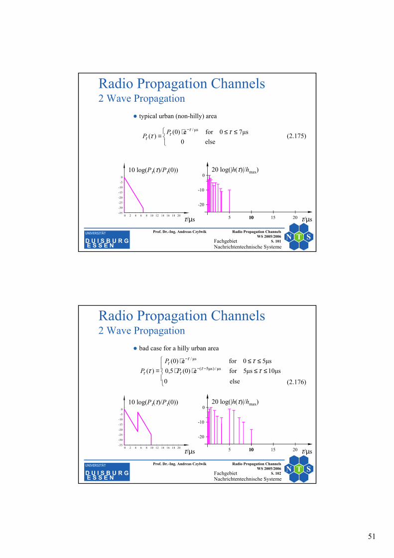
bad case for a hilly urban area
≤≤⋅⋅≤≤⋅
= −−
−
else 0µs10µs5fore(0)5,0
µs50for e(0))( µs/)µs5(
µs/
ττ
τ ττ
ττ
τ PP
P
-35
-30
-25
-20
-15
-10
-5
0
0 2 4 6 8 10 12 14 16 18 20
10 log(Pτ(τ)/Pτ(0))
τ/µs
20 log(|h(τ)|/hmax)
τ/µs
(2.176)

52
FachgebietNachrichtentechnische Systeme
N T SUNIVERSITÄT
D U I S B U R GE S S E N
Prof. Dr.-Ing. Andreas Czylwik Radio Propagation Channels WS 2005/2006
S. 103
Radio Propagation Channels2 Wave Propagation
hilly terrain
≤≤⋅⋅≤≤⋅
= −−
⋅−
else 0µs20µs15fore(0)1,0
µs20for e(0))( µs/)µs15(
µs/5,3
ττ
τ ττ
ττ
τ PP
P
-35
-30
-25
-20
-15
-10
-5
0
0 2 4 6 8 10 12 14 16 18 20
10 log(Pτ(τ)/Pτ(0))
τ/µs
20 log(|h(τ)|/hmax)
τ/µs
(2.177)
FachgebietNachrichtentechnische Systeme
N T SUNIVERSITÄT
D U I S B U R GE S S E N
Prof. Dr.-Ing. Andreas Czylwik Radio Propagation Channels WS 2005/2006
S. 104
Radio Propagation Channels2 Wave Propagation
Short term fadingRayleigh fading with Jakes Doppler spectrum (non-frequency-selective)Logarithmic representation
-40
-30
-20
-10
0
10
0 2 4 6 8 10 12-40
-30
-20
-10
0
10
7.0 7.5 8.0 8.5 9.0
10 log(|A(t)|2/⟨|A(t)|2⟩)
t⋅fmaxx/λ
t⋅fmaxx/λ
10 log(|A(t)|2/⟨|A(t)|2⟩)
53
FachgebietNachrichtentechnische Systeme
N T SUNIVERSITÄT
D U I S B U R GE S S E N
Prof. Dr.-Ing. Andreas Czylwik Radio Propagation Channels WS 2005/2006
S. 105
Radio Propagation Channels2 Wave Propagation
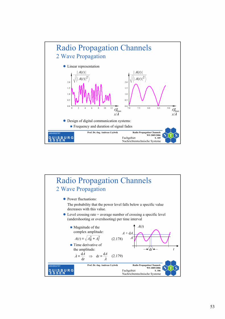
Linear representation
Design of digital communication systems: Frequency and duration of signal fades
0.0
0.5
1.0
1.5
2.0
0 2 4 6 8 10 120.0
0.5
1.0
1.5
2.0
7.0 7.5 8.0 8.5 9.0t⋅fmaxx/λ
t⋅fmaxx/λ
2|)(|
|)(|
tA
tA2|)(|
|)(|
tA
tA
FachgebietNachrichtentechnische Systeme
N T SUNIVERSITÄT
D U I S B U R GE S S E N
Prof. Dr.-Ing. Andreas Czylwik Radio Propagation Channels WS 2005/2006
S. 106
Radio Propagation Channels2 Wave Propagation
Power fluctuations:The probability that the power level falls below a specific value decreases with this value.Level crossing rate = average number of crossing a specific level (undershooting or overshooting) per time interval
Magnitude of thecomplex amplitude:
Time derivative ofthe amplitude:
22)( IR AAtA +=
t
A(t)
A + dA A
dt
AAt
tAA
&& dd
dd =⇒=
(2.178)
(2.179)

54
FachgebietNachrichtentechnische Systeme
N T SUNIVERSITÄT
D U I S B U R GE S S E N
Prof. Dr.-Ing. Andreas Czylwik Radio Propagation Channels WS 2005/2006
S. 107
Radio Propagation Channels2 Wave Propagation
Probability that the amplitude and ist derivative are in the range:
Average time duration that the amplitude and its derivative can be found in D during a time interval of length T :
Average number of level crossings (over- or undershootings):
dd AAAAAAD &&K&K +∩+=
(2.180)AAAAfAAP AA&&& & dd),(),(d ,=
(2.182)
(2.181)AAAAfTAAPTAAT AA&&&& & dd),(),(d),(d ,⋅=⋅=
AAAAfT
AA
AAAAfTt
AATAAN AAAA
T &&&
&
&&&& &
&d),(d
dd),(d
),(d),(d ,, ⋅=
⋅==
FachgebietNachrichtentechnische Systeme
N T SUNIVERSITÄT
D U I S B U R GE S S E N
Prof. Dr.-Ing. Andreas Czylwik Radio Propagation Channels WS 2005/2006
S. 108
Radio Propagation Channels2 Wave Propagation
Number of level crossings per time interval T for the interval of time derivatives :
Number of all level crossings per time:
(2.183)
(2.184)
AAAAfT
AANAAN AAT &&&
&&&
& d),(),(d),(d ,==
A&d
∫∫∞∞
==0
,0
d),(d),(d)( AAAAfAAANAN AA&&&&&&& &

55
FachgebietNachrichtentechnische Systeme
N T SUNIVERSITÄT
D U I S B U R GE S S E N
Prof. Dr.-Ing. Andreas Czylwik Radio Propagation Channels WS 2005/2006
S. 109
Radio Propagation Channels2 Wave Propagation
Joint probability density function of a complex Gaussian process with „Jakes“ Doppler spectrum:
with
and (2.187)
(2.185)
(2.186)
),(, AAf AA&&
)()(eeπ21),(
2
22
2
22
2, AfAfAAAf AA
A
A
A
AAA
AA ⋅=⋅=−−
&& &
&
&&
& σσ
σσ
2I
2R
2 AAA ==σ
2dd
dd 2
max22
I2
R2 ωσσ ⋅=
=
= AA t
At
A&
FachgebietNachrichtentechnische Systeme
N T SUNIVERSITÄT
D U I S B U R GE S S E N
Prof. Dr.-Ing. Andreas Czylwik Radio Propagation Channels WS 2005/2006
S. 110
Radio Propagation Channels2 Wave Propagation
Number of all over- and undershootings per time interval:
(2.190)
(2.188)
(2.189)
2
2
2
2
2
2
2
2
2
2
2
2
2max22
0
2222
2
0
22
0,
eππ2
e
eπ21e
deπ21e
d),()(
AA
AA
AA
A
A
A
A
A
A
AA
A
A
A
A
A
A
AA
AfA
A
AAA
AAAAfAN
σσ
σσ
σσ
σσ
σ
σσσ
σσ
−−
∞−−
−∞−
∞
=⋅=
−
⋅⋅=
⋅⋅=
=
∫
∫
&
&
&&
&
&
&
&
& &&
&&&&
(2.191)

56
FachgebietNachrichtentechnische Systeme
N T SUNIVERSITÄT
D U I S B U R GE S S E N
Prof. Dr.-Ing. Andreas Czylwik Radio Propagation Channels WS 2005/2006
S. 111
Radio Propagation Channels2 Wave Propagation
Substitution:
Number of over- and undershootings per wavelength:
(2.192)
(2.193)2
eπ2)( maxRRfRN −⋅⋅⋅=&
2
2
2 A
ARσ
=
2eπ2
max
RRfN
vNTNN −⋅⋅==⋅=∆⋅=∆
&&& λ
λλ (2.194)
FachgebietNachrichtentechnische Systeme
N T SUNIVERSITÄT
D U I S B U R GE S S E N
Prof. Dr.-Ing. Andreas Czylwik Radio Propagation Channels WS 2005/2006
S. 112
Radio Propagation Channels2 Wave Propagation
level crossing rate (average number of crossings of the level Rper wavelength)
-2.5
-2.0
-1.5
-1.0
-0.5
0.0
-60 -50 -40 -30 -20 -10 0 10
0.0
0.2
0.4
0.6
0.8
1.0
-30 -20 -10 0 1020 lg R
maxfNN&
=∆ λ
=∆
maxlg
fNN&
λ
20 lg R

57
FachgebietNachrichtentechnische Systeme
N T SUNIVERSITÄT
D U I S B U R GE S S E N
Prof. Dr.-Ing. Andreas Czylwik Radio Propagation Channels WS 2005/2006
S. 113
Radio Propagation Channels2 Wave Propagation
Average time interval between two fades:
Average fade duration:
)()()(
)(1
)()(0
00F
0
0F0 RN
RRPRT
RN
RTRRP&
&
<=⇒=<
)(1RN&
)(F RT
2
2
e2π
e1)(max
F R
R
RfRT
−
−
⋅⋅⋅
−=
−⋅⋅
⋅= 1e1
2π1)(
2
maxF
RRf
RT
(2.195)
(2.196)
(2.197)
FachgebietNachrichtentechnische Systeme
N T SUNIVERSITÄT
D U I S B U R GE S S E N
Prof. Dr.-Ing. Andreas Czylwik Radio Propagation Channels WS 2005/2006
S. 114
Radio Propagation Channels2 Wave Propagation
Average fade length:
Average fade duration:
−⋅⋅=⋅=∆ 1e1
2π)(
2FF
RR
vRTx λ (2.198)
-3.5
-3.0
-2.5
-2.0
-1.5
-1.0
-0.5
0.0
-60 -50 -40 -30 -20 -10 0 10
0.0
0.2
0.4
0.6
0.8
1.0
-30 -20 -10 0 10
∆=⋅
λF
maxFlg xfT
λF
maxFxfT ∆=⋅
20 lg R20 lg R

58
FachgebietNachrichtentechnische Systeme
N T SUNIVERSITÄT
D U I S B U R GE S S E N
Prof. Dr.-Ing. Andreas Czylwik Radio Propagation Channels WS 2005/2006
S. 115
Radio Propagation Channels2 Wave Propagation
Average fade length and number of fades per wavelength as a function of the fade depth
fade depth in dB: −20 lg R
average fade length in wave lengths ∆x/λ
average number of fades per wave length ∆Nλ
0 0,479 1,043 10 0,108 0,615 20 0,033 0,207 30 0,010 0,066
FachgebietNachrichtentechnische Systeme
N T SUNIVERSITÄT
D U I S B U R GE S S E N
Prof. Dr.-Ing. Andreas Czylwik Radio Propagation Channels WS 2005/2006
S. 116
Radio Propagation Channels2 Wave Propagation
Spatial correlation
Correlation at the mobile station has already been treated:
Transformation of coordinates:)π2(J)()(E)( max00
* τττ fPNtAtARAA ⋅⋅=+⋅=
)π2(J)()(E)( 00*
λxPNxxAxAxRAA
∆⋅⋅=∆+⋅=∆
λτ
τx
vxffxv ∆=∆⋅=⋅⇒
∆= maxmax
(2.199)
(2.200)
(2.201)

59
FachgebietNachrichtentechnische Systeme
N T SUNIVERSITÄT
D U I S B U R GE S S E N
Prof. Dr.-Ing. Andreas Czylwik Radio Propagation Channels WS 2005/2006
S. 117
-3 -2 -1 1 2 3
RAA(∆x)
∆x/λ
Radio Propagation Channels2 Wave Propagation
The spatial correlation doesnot depend on the direction
The correlation decreasesfast within small distances
FachgebietNachrichtentechnische Systeme
N T SUNIVERSITÄT
D U I S B U R GE S S E N
Prof. Dr.-Ing. Andreas Czylwik Radio Propagation Channels WS 2005/2006
S. 118
Radio Propagation Channels2 Wave Propagation
Correlation at the base station
Calculation procedure similar as for the calculation at the mobile station: base station moves with velocity v.
Differences:
No local scatterers close to the base station.
All waves arrive from a narrow angular range.
Direction of movement of the base station plays an important role
Assumptions
All (micro-)paths exhibit the same power.
Path amplitudes are statistically independent from angles of arrival.

60
FachgebietNachrichtentechnische Systeme
N T SUNIVERSITÄT
D U I S B U R GE S S E N
Prof. Dr.-Ing. Andreas Czylwik Radio Propagation Channels WS 2005/2006
S. 119
Radio Propagation Channels2 Wave Propagation
Approximation: angles of arrival are equally distributed within a small angular range
(2.202)
BS
∆ϕ
ϕ0MS
+≤≤−
∆=∆∆
else0
for1)( 2020
ϕϕ
ϕϕτϕ
ϕϕf
FachgebietNachrichtentechnische Systeme
N T SUNIVERSITÄT
D U I S B U R GE S S E N
Prof. Dr.-Ing. Andreas Czylwik Radio Propagation Channels WS 2005/2006
S. 120
Radio Propagation Channels2 Wave Propagation
Calculation of the autocorrelation function corresponding to Eq. (2.157):
No analytical solution ⇒ numerical evaluation
(2.203)
∫−
∆−
∆−
−
⋅⋅=
⋅⋅=∆⇔
⋅⋅=
π
π
)cos(π2j0
)cos(π2j0
)cos(j0
d)(e
eE)(
eE)( max
ϕϕ
τ
ϕϕ
λ
ϕλ
τϕω
fPN
PNxR
PNR
x
x
AA
AA
(2.204)
(2.205)

61
FachgebietNachrichtentechnische Systeme
N T SUNIVERSITÄT
D U I S B U R GE S S E N
Prof. Dr.-Ing. Andreas Czylwik Radio Propagation Channels WS 2005/2006
S. 121
Radio Propagation Channels2 Wave Propagation
Autocorrelation function at the base station
0.0
0.2
0.4
0.6
0.8
1.0
0 10 20 30 40 500.0
0.2
0.4
0.6
0.8
1.0
0 10 20 30 40 50
RAA(∆x) RAA(∆x)
∆x/λ ∆x/λ
ϕ0 = 0°ϕ0 = 30°ϕ0 = 60°ϕ0 = 90°
∆ϕ = 2,5°∆ϕ = 5°∆ϕ = 10°∆ϕ = 20°
ACF for different average angles of arrival ϕ0 and angular spread ∆ϕ = 5°
ACF for different angular spreads ∆ϕfor a fixed angle of arrival ϕ0 = 60°
FachgebietNachrichtentechnische Systeme
N T SUNIVERSITÄT
D U I S B U R GE S S E N
Prof. Dr.-Ing. Andreas Czylwik Radio Propagation Channels WS 2005/2006
S. 122
Radio Propagation Channels2 Wave Propagation
Path loss modelsAverage attenuation as a function of distance: averaging across medium distances (hundreds of wavelengths) so that fast fading and shadowing effects cancel out
Free-space propagation:
Lee‘s empirical approach for propagation in real environments:
2
RTT
Rπ4
⋅⋅=fd
cGGPP
000
0R kff
ddPP
n⋅
⋅
⋅=
−−γ
(2.206)
(2.207)