Radio Network Management in Cognitive LTE-Femtocell … · proposed to support seamless handover...
212
Radio Network Management in Cognitive LTE-Femtocell Systems A thesis submitted in partial fulfilment of the requirements for the degree of Doctor of Philosophy (PhD) Electronic and Computer Engineering School of Engineering and Design Brunel University United Kingdom By Saba Al-Rubaye January 2013
Transcript of Radio Network Management in Cognitive LTE-Femtocell … · proposed to support seamless handover...

Radio Network Management in Cognitive LTE-Femtocell Systems
A thesis submitted in partial fulfilment of the requirements for the degree
of Doctor of Philosophy (PhD)
Electronic and Computer Engineering
School of Engineering and Design Brunel University United Kingdom
By
Saba Al-Rubaye
January 2013

i
Abstract
There is a strong uptake of femtocell deployment as small cell application
platforms in the upcoming LTE networks. In such two-tier networks of LTE-
femtocell base stations, a large portion of the assigned spectrum is used
sporadically leading to underutilisation of valuable frequency resources.
Novel spectrum access techniques are necessary to solve these current spectrum
inefficiency problems. Therefore, spectrum management solutions should have
the features to improve spectrum access in both temporal and spatial manner.
Cognitive Radio (CR) with the Dynamic Spectrum Access (DSA) is considered
to be the key technology in this research in order to increase the spectrum
efficiency. This is an effective solution to allow a group of Secondary Users
(SUs) to share the radio spectrum initially allocated to the Primary User (PUs) at
no interference.
The core aim of this thesis is to develop new cognitive LTE-femtocell systems
that offer a 4G vision, to facilitate the radio network management in order to
increase the network capacity and further improve spectrum access probabilities.
In this thesis, a new spectrum management model for cognitive radio networks is
considered to enable a seamless integration of multi-access technology with
existing networks. This involves the design of efficient resource allocation
algorithms that are able to respond to the rapid changes in the dynamic wireless
environment and primary users activities. Throughout this thesis a variety of
network upgraded functions are developed using application simulation
scenarios. Therefore, the proposed algorithms, mechanisms, methods, and system
models are not restricted in the considered networks, but rather have a wider
applicability to be used in other technologies.
This thesis mainly investigates three aspects of research issues relating to the
efficient management of cognitive networks: First, novel spectrum resource
management modules are proposed to maximise the spectrum access by rapidly
detecting the available transmission opportunities. Secondly, a developed pilot
power controlling algorithm is introduced to minimise the power consumption by
considering mobile position and application requirements. Also, there is
investigation on the impact of deploying different numbers of femtocell base
stations in LTE domain to identify the optimum cell size for future networks.
Finally, a novel call admission control mechanism for mobility management is
proposed to support seamless handover between LTE and femtocell domains.
This is performed by assigning high speed mobile users to the LTE system to
avoid unnecessary handovers.
The proposed solutions were examined by simulation and numerical analysis to
show the strength of cognitive femtocell deployment for the required
applications. The results show that the new system design based on cognitive
radio configuration enable an efficient resource management in terms of
spectrum allocation, adaptive pilot power control, and mobile handover. The
proposed framework and algorithms offer a novel spectrum management for self-
organised LTE-femtocell architecture.
Eventually, this research shows that certain architectures fulfilling spectrum
management requirements are implementable in practice and display good
performance in dynamic wireless environments which recommends the
consideration of CR systems in LTE and femtocell networks.

ii
Acknowledgements
All praise is to 'My God' for his grace, blessing, mercy and giving me the
ability to complete this thesis. I'm feeling of his support toward me in each stage
of my life.
I would like to express my sincere gratitude to my supervisor professor 'John
Cosmas' for his unflinching support, continuous motivation for quality work and
encouragement. His support was vital to achieving this degree. His momentum
and spontaneity has always restored an aura of research at the Wireless Network
and Communication Centre (WNCC).
I would like to acknowledge the encouraging and supportive attitude of all
staff members at Brunel University for promoting research especially. All of
them have been absolutely professional.
Finally, my deepest gratitude goes to my husband 'Anwer' for his devotion,
love, support, patience, and steady encouragement. I want to thank him from my
heart for everything he has done.

iii
Declaration
I hereby declare that the research documented in this thesis is my own unaided
work, both in conception and execution. Information derived from the published
and unpublished work of others has been acknowledged in the text and
references are given in the list of sources. The thesis itself was composed and
originated entirely by myself in the Wireless Networks and Communications
Centre, Electronic and Computer Engineering Department, School of
Engineering and Design at Brunel University.
Copyright © by
Saba Al-Rubaye
2013, London, UK

iv
Table of Contents
Abstract ………………………………...……….………………….………………….
Acknowledgements ………………………………..……………….………………….
Declaration……………………………………………………………………………..
Table of Contents …………………………………………………….……………….
List of Figures …………………………..………..………………………..………….
List of Tables ………………………………..……….…………………….…………..
List of Abbreviations…………………………….………………………………..…..
List of Publications…………………………………………………………………….
Chapter 1: Introduction...................................................................................
1.1 Motivation …………………....................................................................................
1.2 Problem Statement……………………………………………………………..…..
1.3 Aims of Research……………………………………………………….………….
1.4 Methodology ……………………...........................................................................
1.5 Thesis Novel Contributions………………………………………………………..
1.5.1 Novel Spectrum Resource Management Model………………………….….
1.5.2 Spectrum Allocation Technique……………………………………….…….
1.5.3 New Power Management Approaches……………………………………….
1.5.4 Novel Mobility Management Mechanism…………………….……………..
1.6 Thesis Organisation…………………………………………………….…..……..
1.7 References………………………………………………………………………….
Chapter 2: Background and Technical Challenges in
Cognitive LTE Femtocell Systems ………….…….………
2.1 Introduction ……………………………..............................................................
2.2 Current Standardisation ……….…..……………………………………………...
2.3 Long Term Evolution (LTE) Technology …………………………………………
2.3.1 LTE-OFDM Technique…………………………………………………………..
2.4 Femtocell Networks……………………………………………………………..…
2.4.1 The Need for Small-Cell Base Station………………………………….……
2.4.2 Femtocell Deployment Aspects………………………………………….…..
2.4.3 Access Mechanisms……………………………………………………….….
2.4.3.1 Close Access Method……………………………………………….…
2.4.3.2 Open Access Method……………………………................................
i
ii
iii
iv
viii
xi
xii
xv
1
1
4
5
6
7
9
10
10
10
11
13
15
16
18
18
19
23
24
26
27
27
28

v
2.4.3.3 Hybrid Access Method………………………………………………...
2.5 Cognitive Radio Technique………………………………………………..…….…
2.5.1 Cognitive Networks Functions………………………………………….……
2.5.1.1 Spectrum Sensing……………………………………………………..
2.5.1.2 Spectrum Sharing……………………………………………………...
2.5.1.3 Spectrum Decision……………………………………………….……
2.5.1.4 Location Identification………………………………….…………….
2.5.1.5 Network Discovery……………………………………………………
2.6 Cognitive Network Management………………………………………………….
2.6.1 Centralised Network Architecture……………………………………………
2.6.2 Distributed Network Architecture……………………………….……………
2.6.3 Hybrid Network Architecture………………………………….……………..
2.7 Cognitive Femtocell in LTE Systems……………………………………..……….
2.8 Technical Challenges………………………………………………………………
2.8.1 Spectrum Decision and Allocation Efficiency………………………….……
2.8.2 Providing QoS Awareness over an Internet Backhaul……………………….
2.8.3 Resource Management and Network Planning………………………………
2.8.4 Interference Optimisation Problem……………………………………….….
2.8.5 Mobility Problems……………………………………………………………
2.8.6 Self-Organisation and Power Efficiency Challenges………………………...
2.9 Conclusion…………………………………………………………………………
2.10 References……………………………………………………………………..….
Chapter 3: Spectrum Management in Cognitive Radio Systems
3.1 Introduction………………………………………………………….…….……….
3.2 Related work……………………………………………………………………….
3.3 Problem Formulation………………………………………………………………
3.3.1 Free Channel Occurrence……………………………………………………..
3.4 System Model……………………………………………………………………...
3.4.1 Spectrum Sensing Model……………………………………………..............
3.4.2 Interference Avoidance Module……………………………………….……..
3.4.3 Spectrum Decision Making…………………………………………….…….
3.4.4 Scheduling Mechanism……………………………………………………….
3.5 System Implementation…………………………………………………………….
3.5.1 Integrating the New Cognitive System……………………………………….
3.5.1.1 Generate Management Process Model………………...………………
28
30
31
32
32
33
34
34
34
34
36
37
38
41
41
43
44
44
47
48
49
50
56
57
58
61
61
62
64
66
67
69
74
75
78
vi
3.5.1.2 Generate Spectrum Resource Model……………………...………..….
3.6 System Performance………………………………………………………………..
3.6.1 Results………………………………………………………………………...
3.7 Spectrum Utilisation based Bandwidth Allocation……………………………..….
3.7.1 Channel Allocation in LTE and femtocell……………………………...….…
3.7.2 Queuing Mechanism…………………………………………………….……
3.8 System Model based Priority Spectrum Allocation………………………………..
3.8.1 Spectrum Allocation Technique………………………………………….…..
3.8.2 System Assessment…………………………………………………………..
3.9 System performance………………………………………………………….….…
3.9.1 System Specification………………………………………………………….
3.9.2 Results and Analysis…………………………………………………….……
3.10 Conclusion………………………………………………………………….…….
3.11 References………………………………………………………………….….….
Chapter 4: Radio Power Management and LTE Coverage
Planning ….………………………………………………….…...
4.1 Introduction……………………………………………………….…………….….
4.2 Related Work……………………………………………………….………….…..
4.3 Power Management System………………………………………………….…….
4.3.1 System Formulation…………………………………………………………..
4.3.2 Proposed Scheme: Adaptive Power Control…………………………………
4.3.3 Radio Transceiver Pipeline Models …………………………………….…...
4.4 Simulation……………………………………………………………………...…..
4.5 Power Consumption Estimation…………………………………………………..
4.5.1 Cell Coverage Area……………………………………………………..….…
4.5.2 Area Spectral Efficiency……………………………………………….……..
4.6 Power Consumption Modeling……………………………………………………
4.7 System Power Consumption Evaluated……………………………………………
4.7.1 Numerical Results…….……………………………………………………...
4.7.2 Simulation Results……………………………………………………………
4.8 Site Energy Consumption Modeling………………………………………………
4.9 Efficient Energy Scenario…………………………………………………….……
4.10 Numerical Energy Consumption Analysis………………………………………
4.11 Conclusion………………………………………………………………………..
79
80
81
86
86
88
89
90
93
94
94
96
100
100
106
107
109
111
112
113
117
120
125
125
128
129
131
131
133
136
137
138
141

vii
4.12 Reference………………………………………………………………………….
Chapter 5: Novel Mobility Management for LTE based
Femtocell Networks…………………..……………….…….…
5.1 Introduction………………………………………………………………….……..
5.2 Handover procedure……………………….………………………………………
5.2.1 Cell Discovery and Measurement….…………………………………….…..
5.3 Mobility Management……..………………………………………………….……
5.3.1 Handover Management Operations………………………………….….……
5.3.2 Location management…………………………………………………..…….
5.3.3 Mobile IPv6 Network Layer Performance……………………………………
5.4 Mobility Management in LTE Zones…………………………………………..…..
5.5 Femtocell Migration between LTE Zones…………………………………………
5.6 Handover Call Flow………………………………………………………….…….
5.6.1 Hand-in Procedure……………………………………………………………
5.6.2 Hand-out Procedure………………………………………………………….
5.7 System Model……………………………………………………………….……..
5.7.1 Markov Chain for Handover Decisions………………………………………
5.7.2 Novel Mechanism for Call Admission Control………………………………
5.8 Cognitive Node Implementation in OPNET……………………………………….
5.9 System Configuration……………………………………………………………...
5.9.1 Simulation Results……………………………………………………………
5.10 Conclusion……………………………………………………………………..…
5.11 References…………………………………………………………………..…….
Chapter 6: Conclusions and Future Work……………………………..
6.1 Conclusions………………………………………………………………………...
6.2 Future Work………………………………………………………………………..
6.2.1 Adaptive Spectrum Sensing………………………………………………….
6.2.2 Capacity Improvements in LTE with Power Control………………………...
6.2.3 Adaptive Coverage and Handover……………………………………………
6.2.4 Controlling Radio Interference in OFDM Femtocell…………………………
Appendix A: Channel Negotiation in Cognitive Radio Network……………..........
141
145
146
148
149
150
151
152
153
155
158
161
162
163
166
166
169
173
177
180
184
184
188
189
191
191
192
192
192
193

viii
List of Figures
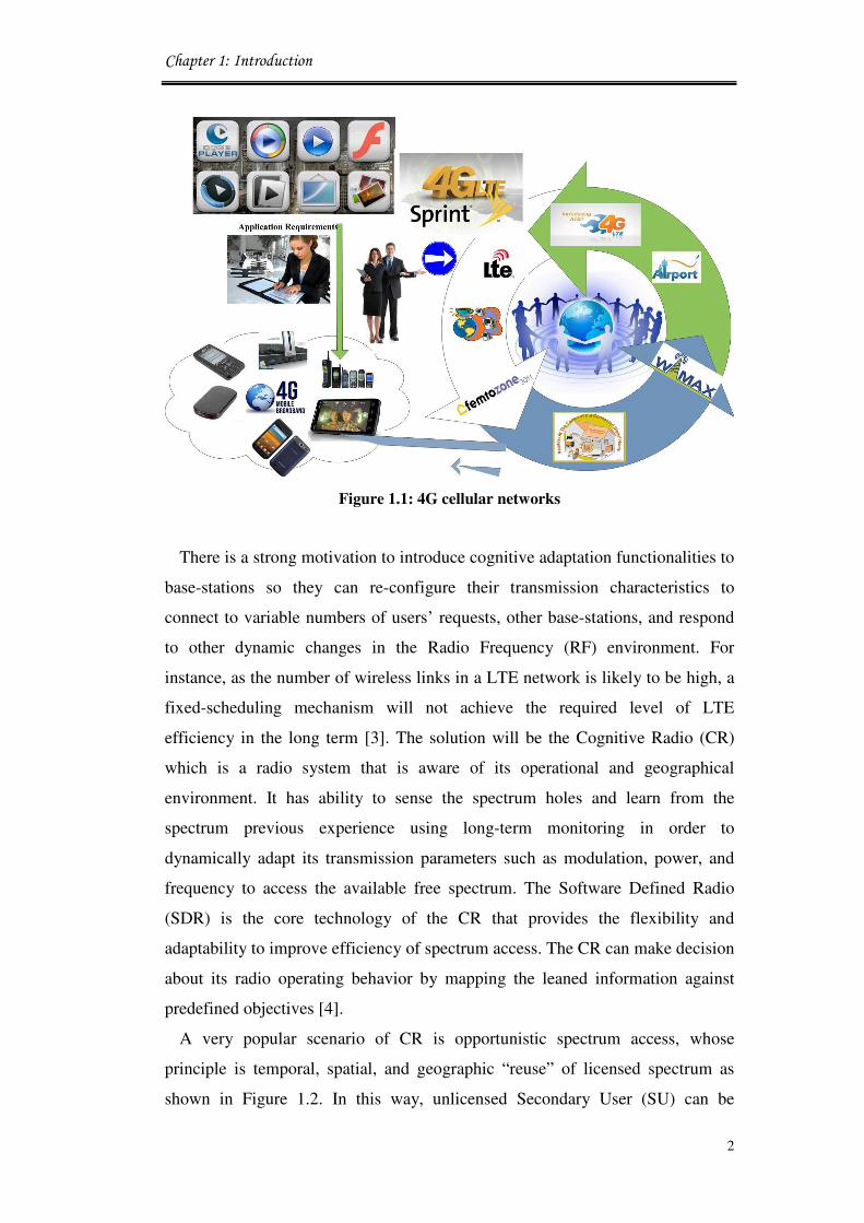
Figure 1.1: 4G cellular networks……..…………………………………………… 2
Figure 1.2: Cognitive radio system scenarios……………………...……………… 3
Figure 1.3: Complete system diagram of research contributions…………………. 8
Figure 2.1: Future 4G systems with different technical applications……………... 17
Figure 2.2: Time-frequency representation of OFDM subcarrier………………… 20
Figure 2.3: Frequency bandwidth of OFDM……………………………….….….. 21
Figure 2.4: LTE frame structure……………………………………………….….. 22
Figure 2.5: Femtocell deployments in 4G wireless systems……………………… 24
Figure 2.6: Femtocell knowledge developed…..………………………………….. 25
Figure 2.7: Femtocell access methods……………………………………….……. 29
Figure 2.8 Spectrum opportunities for cognitive radio…………………………... 30
Figure 2.9: Cognitive radio operations……………..……………………………... 32
Figure 2.10: Centralised network management architecture……………………….. 35
Figure 2.11: Distributed network architecture……………...………………………. 36
Figure 2.12: Hybrid network architecture……………...…….…………………….. 38
Figure 2.13: Framework for green network managements……..…………….……. 40
Figure 2.14: Spectrum sub-channels division……………………………………… 42
Figure 2.15: Mobile (IPTV) technologies for next-generation systems………….... 43
Figure 2.16: Macrocell downlink interference to the femtocell user……….……… 45
Figure 2.17: Downlink interference in LTE/femtocell OFDM co-channel………… 46
Figure 3.1: Spectrum management architecture for cognitive radio networks…… 57
Figure 3.2: Functional design of spectrum management……………………….…. 63
Figure 3.3: Function of spectrum sensing………………………………………… 64
Figure 3.4: Avoiding interference at the edge of the primary’s coverage.………... 66
Figure 3.5: Spectrum decision function…………………………………………… 68
Figure 3.6 Robing Round schedule approach……………………………………. 70
Figure 3.7: Class scheduler design…….………………………………………….. 73
Figure 3.8: Structure of DSA negotiation policy……………………………..…... 74
Figure 3.9: Cognitive LTE/femtocell systems testbed in OPNET………………... 75
Figure 3.10: Modified node modules in OPNET……………………………….….. 76
Figure 3.11: Channel access mechanism in MAC (Process Domain)……………… 77
Figure 3.12: Management module (Process Domain)……………………………… 78
Figure 3.13: Resource allocation module (Process Domain)………………………. 80
Figure 3.14: BER vs. number of site femtocell users………………………………. 83

ix
Figure 3.15: SNR vs number of site femtocell users……………………………….. 83
Figure 3.16 Power vs number of site femtocell users……………………………... 84
Figure 3.17: Throughput vs number of site femtocell users………………………... 85
Figure 3.18: End-to-end time delay vs number of site femtocell users…………….. 86
Figure 3.19 Various channel allocations……………………………………….….. 87
Figure 3.20: OFDM, a) Multicarrier transmission, b) orthogonally……….….……. 89
Figure 3.21: Scheme for allocating UEs to the OFDM sub-bands………..………... 92
Figure 3.22: Channels free time as a percentage ……………………………….….. 94
Figure 3.23: Throughputs of the two applications Video and VoIP…………….…. 97
Figure 3.24: Comparison of End-to-End time delay……………………………….. 97
Figure 3.25: Medium access delay for the two applications Video and VoIP...…... 98
Figure 3.26: Traffic sent and received for Video…………………………………... 98
Figure 3.27: Traffic sent and received for VoIP……………………………………. 99
Figure 4.1: Cooperative in heterogeneous networks……………………………… 107
Figure 4.2: Management approach for power efficiency of 4G radio
communications LTE system………………………………………….
111
Figure 4.3: Adaptive coverage adjustment for femtocell management…………… 112
Figure 4.4: Femtocell coverage as a function of mobile distance …………….….. 114
Figure 4.5: Sample of power management project in OPNET17.1………………. 120
Figure 4.6: Power consumption as a function of traffic…………………………... 122
Figure 4.7: Mobile power received as a function of connection time…………….. 123
Figure 4.8: Time delay improvements due to the LTE femtocell design…………. 124
Figure 4.9: SNR improvements due to the LTE femtocell design………………... 125
Figure 4.10: Networks node coverage for different size areas.……………………. 126
Figure 4.11: Hexagonal cell site types……..………………………………………. 127
Figure 4.12: Regular grid of base stations and corresponding cell geometry with
inter site distance ISD and cell area �����……………………………..
128
Figure 4.13: Area power consumption vs ISD………………………………….….. 132
Figure 4.14: Okumura–Hata model………………………………………………… 133
Figure 4.15: Downlink throughput delivered from LTE layer………………..……. 134
Figure 4.16: Impact of system load……………………………………………...…. 135
Figure 4.17: Average system end to end packet delays…………………………..… 136
Figure 4.18: Energy consumption vs ratio connection of LTE/femtocell….…….… 140
Figure 5.1: Handover procedure in 3GPP-LTE…………………………………… 147
Figure 5.2: Admission control procedure…………………………………………. 149
Figure 5.3: Handover of management operations……………….………………... 151

x
Figure 5.4: Handover routing from node A to node E……………………………. 152
Figure 5.5:
Figure 5.6:
Figure 5.7:
Mobile IPv6 architecture and operations……...………………………
Multi-access networks of femtocell and LTE base stations…………...
Femtocell migrations between two LTE zones………………………..
154
156
159
Figure 5.8: Handover scenario in femtocell networks…………………………….. 161
Figure 5.9: Handover from macrocell to femtocell…………….…………………. 164
Figure 5.10: Handover from femtocell to macrocell……………………………….. 165
Figure 5.11: Multi server queues systems………………………………………….. 166
Figure 5.12: Markov chain model of LTE-femtocell handover scheme…………… 167
Figure 5.13: Markov model………….……………………………………………... 168
Figure 5.14: Handover decisions in the hierarchical system model………………... 170
Figure 5.15: New CAC mechanism for handover call authentication……………... 172
Figure 5.16: Node process model in OPNET17.1………………………….………. 174
Figure 5.17: Node modification by adding admission control process…………….. 174
Figure 5.18: Call admission control “process model”……………………………… 175
Figure 5.19: Simulation scenarios for the proposed handover mechanism.……….. 178
Figure 5.20: Scenario (1) for handover LTE/femtocell in OPNET17.1……………. 179
Figure 5.21: Retransmission rate vs number of handover………………………….. 180
Figure 5.22: Latency of the successful handover…………………………………... 181
Figure 5.23: Throughput graphs for simulated scenarios….….………………….... 182
Figure 5.24: Total number of admitted GBR bearers with access time……………. 183
xi
List of Tables Table 3.1: New LTE/femtocell system characteristics…………………..…… 82
Table 3.2: Spectrum allocation system parameters………………………...…. 95
Table 4.1: System parameters for LTE-femtocell network……………...……. 121
Table 4.2: System theoretical characteristics…………….………………..…. 139
Table 5.1: Simulation parameters for handover project…………………….. 177

xii
List of Abbreviations 3G Third Generation
3GPP 3rd
Generation Partnership Project
4G Fourth Generation
ACK ACKnowledgement
AD Administrative Domain
AN Access Network
AODV Ad hoc On-Demand Distance Vector
APC Area Power Consumption
BE Best Effort
BER Bit Error Rate
CAC Call Admission Control
CFS Cognitive Femtocell Systems
CN Correspondent Node
CoA Care-of Address
CR Cognitive Radio
CRM Cognitive Resource Management
CRN Cognitive Radio Network
CSCC Common Spectrum Control Channel
CSG Closed Subscriber Group
CSMA/CA Carrier Sense Multiple Access with Collision Avoidance
CTS Clear-to-Send
CW Contention Window
DC Direct Current
DHCP Dynamic Host Configuration Protocol
DL Downlink
DL-DPCH Downlink Dedicated Physical Channel
DSA Dynamic Spectrum Access
DSL Digital Subscriber Line
EPC Evolved Packet Core
FA Foreign Agent
FBS Femtocell Base Station

xiii
FCC Federal Communications Commission
FEC Forward Error Correction
FIFO First In First Out
FN Foreign Network
FUE Femtocell Users Equipment
GBR Guaranteed Bit Rate
HA Home Agent
HeNB Home Evolved Node-B
HNB-GW Home Node B- Network Gateway
HSDPA High Speed Downlink for Packet Access
HSPA High-Speed Packet Access
HTTP Hypertext Transfer Protocol
Hz Hertz
IF Intermediate Frequency
IP Internet Protocol
IPTV Internet Protocol Television
ISD Inter Side Distance
LTE Long Term Evolution
M/M/1 Markov/Markov/1 Queue
MAC Medium Access Control
MANET Mobile Ad-Hoc Network
MH Mobile Host
MIMO Multiple Input Multiple Output
MIPv6 Mobile Internet Protocol Version 6
MLB Mobility Load Balancing
MN Mobile Node
MUE Mobile User Equipment
NET Network
NRTPS Non- Real-Time Polling Services
OFDM Orthogonal Frequency Division Multiplexing
OPNET Optimized Network Engineering Tool
PDU Protocol Data Unit
PHY Physical Layer

xiv
PQ Priority Queuing
PRBs Physical Resource Blocks
PU Primary User
QoS Quality of Services
QPSK Quadrature Phase-Shift Keying
RAN Radio Access Network
RBR Requested Bandwidth Range
RF Radio Frequency
RNC Radio Network Controller
RSRP Reference Signal Received Power
RSS Received Signal Strength
RTPS Real Time Polling Services
RTS Request-to-Send
SDR Soft Defined Radio
SINR Signal-to-Interference-Noise-Ratio
SNR Signal-to-Noise-Ratio
SU Secondary User
TDA Transmission Data Attributes
TV Television
UDP User Datagram Protocol
UE Users Equipment
UGS Unsolicited Grant Service
UL Up Link
UMTS Universal Mobile Telecommunications System
VoIP Voice over IP
WiMax Worldwide Interoperability for Microwave Access
WLANs Wireless Local Area Network

xv
List of Publications
Book Chapters:
[1] S. Al-Rubaye and J. Cosmas, “Technical Challenges in 4G Cognitive
Femtocell Systems,” In Self-Organization and Green Applications in
Cognitive Radio Networks, Edited by A. Al-Dulaimi, J. Cosmas, and A.
Mohammed to be published by IGI Global, February 2013.
[2] S. Al-Rubaye, A. Al-Dulaimi, and J. Cosmas, Spectrum Handover Strategies
for Cognitive Femtocell Networks, In Femtocell Communications and
Technologies: Business Opportunities and Deployment Challenges, Edited
by R. Saeed, B. Chaudhari, and R. Mokhtar, IGI Global, July 2012.
[3] A. Al-Dulaimi, S. Al-Rubaye, and J. Cosmas, “Adaptive Coexistence between
Cognitive and Fibre Networks,” In Wireless Multi-Access Environments and
Quality of Service Provisioning: Solutions and Application,” Edited by G.
Muntean and R. Trestian, IGI Global, January 2012.
Journals:
[4] S. Al-Rubaye and J. Cosmas, “A Novel Power Consumption Modelling for
LTE-Femtocell Networks Deployment,” IEEE Transactions on Vehicular
Technology, submitted 2012.
[5] S. Al-Rubaye and J. Cosmas, “Network Capacity Planning for LTE
Macrocell Systems”, IEEE Transactions on Wireless Communications,
submitted 2012.
[6] S. Al-Rubaye, A. Al-Dulaimi and J. Cosmas, “Cognitive Femtocell, Future
Wireless Networks for Indoor Applications,” IEEE Vehicular Technology
Magazine, vol. 6, no. 1, pp. 44 - 5, 2011.
[7] S. Al-Rubaye, A. Al-Dulaimi, and H. Al-Raweshidy, “Next Generation
Optical Access Network using CWDM Technology,” International Journal
of Communications, Network and System Sciences (IJCNS), no 7, pp. 636-
640, 2009.

xvi
Conferences:
[8] S. Al-Rubaye and J. Cosmas, “Energy efficiency model for LTE/Femtocell
systems,” in Proc. of the 5th
annual student research conference (Rescon12),
Brunel University, London, UK, 2012.
[9] S. Al-Rubaye and J. Cosmas, “Pilot Power Optimization for Autonomous
Femtocell Networks,” In Proc. of the IEEE 7th
International Conference on
Wireless Advanced, Kings College London, UK, 2011.
[10] A. Al-Dulaimi, S. Al-Rubaye and J. Cosmas, “Adaptive Congestion Control
for Mobility in Cognitive Radio Networks,” In Proc. of the IEEE 7th
International Conference on Wireless Advanced, Kings College London,
UK, 2011.
[11] H. AlSabbagh, F. Mahmood, S. Al-Rubaye, and R. Edwards “The Design of
Fractal Antennas for UWB using MoM,” in Proc. of the IEEE/IET 5th
European Conference on Antennas and Propagation, Loughborough
Antennas and Propagation Conference (LAPC), Loughborough , UK, 2011
[12] S. Al-Rubaye, A. Al-Dulaimi and J. Cosmas, “Cognitive Femtocells for
Future Internet base on QoS,” In Proc. of the 25th
Wireless World Research
Forum (WWRF#25), London, UK, 2010.
[13] A. Al-Dulaimi, S. Al-Rubaye, H. Al-Raweshidy, J. Cosmas, and K. K. Loo,
“Multi-Zones of Cognitive to Fibre Networks,” In Proc. of the IEEE/IET
International Symposium on Communication Systems, Networks And Digital
Signal Processing (CSNDSP’10), Newcastle, UK, pp.762 - 765, 2010.
[14] S. Al-Rubaye, “Green Radio over Fibre and Femtocell Access Network,” In
Proc. of the 25th
Wireless World Research Forum (WWRF#25), London,
UK, Nov. 2010.
[15] A. Al-Dulaimi, S. Al-Rubaye, and H. Al-Raweshidy, “Renovate Cognitive
Networks under Spectrum Unavailability,” In Proc. of the IEEE 6th
Advanced International Conference on Telecommunications (AICT 2010),
Barcelona, Spain, pp.41- 45, 2010
[16] A. Al-Dulaimi, S. Al-Rubaye, and H. Al-Raweshidy, “Radio over Fibre
Transceiver Designed for Cognitive Communications Architecture,” In
Proc. of the 25th
Wireless World Research Forum (WWRF#25), London,
UK, Nov. 2010

xvii
[17] E. Kadhum, W. Ismail, and S. Al-Rubaye, “Noise Analysis based on BERT
Using Hardware -in-the-loop co-simulation Based FSK Transceiver Through
a Hybrid DSP/FPGA Platform,” In Proc. of the 25th
Wireless World
Research Forum (WWRF#25), London, UK, Nov 2010.
[18] S. Al-Rubaye, A. Al-Dulaimi, L. AL-Saeed, H. Al-Raweshidy, E. Kadhum,
and W. Ismail, “Development of Heterogeneous Cognitive Radio and
Wireless Access Network,” In Proc. of the 24th
Wireless World Research
Forum (WWRF#24), Penang Island, Malaysia, April 2010.
[19] E. Kadhum, W. Ismail, and S. Al-Rubaye,” Software Digital modems for
Software Defined Radio (SD4R) using Hybrid architecture platform,” In
Proc. of the 24th
Wireless World Research Forum (WWRF#24), Penang
Island, Malaysia, April 2010.
Posters:
[20] S. Al-Rubaye, “Energy Efficiency Scenarios in LTE/Femtocell Systems,” In
Proc. of the Poster Graduate School Conference, Brunel University,
London, UK, 2012.
[21] S. Al-Rubaye, “Cognitive Femtocell for Future Wireless Access Networks,”
In Proc. of the Poster Graduate School Conference, Brunel University,
London, UK, 2011.

Chapter 1: Introduction
1
ChapterChapterChapterChapter 1111
Introduction
1.1 Motivation
An important feature of Long Term Evolution/Third Generation Partnership
Project (LTE/3GPP) systems is that it allows a distributed implementation of
femtocells to meet a variety of service requirements by end users. The femtocell
access points, denoted as Home evolved Node-B (HeNB) in 3GPP, are low cost,
low-power, plug-and-play cellular base stations that provide local broadband
connectivity. These HeNBs will need to possess adaptive/cognitive facilities to
meet the deployment requirements [1].
Current wireless networks are characterised by a static spectrum assignment
policy where government agencies allocate wireless spectrum to licensed holders
on a long term basis for large geographical regions. The limited available
spectrum and inefficient spectrum utilisation make it necessary to develop a new
communication paradigm to exploit the existing wireless spectrum
opportunistically. To address these critical problems, the Federal
Communications Commission (FCC) recently approved the use of unlicensed
devices in licensed bands [2] and this trend is likely to be repeated in other
countries in Europe and around the world. Future wireless communication
systems will be characterised by the coexistence of several different radio access
technologies like Universal Mobile Telecommunications System (UMTS), LTE,
LTE-Advance, and Worldwide Interoperability for Microwave Access (WiMax),
Wireless Local Area Network (WLANs), and femtocell, as shown in Figure 1.1.
Chapter 1: Introduction
2
Figure 1.1: 4G cellular networks
There is a strong motivation to introduce cognitive adaptation functionalities to
base-stations so they can re-configure their transmission characteristics to
connect to variable numbers of users’ requests, other base-stations, and respond
to other dynamic changes in the Radio Frequency (RF) environment. For
instance, as the number of wireless links in a LTE network is likely to be high, a
fixed-scheduling mechanism will not achieve the required level of LTE
efficiency in the long term [3]. The solution will be the Cognitive Radio (CR)
which is a radio system that is aware of its operational and geographical
environment. It has ability to sense the spectrum holes and learn from the
spectrum previous experience using long-term monitoring in order to
dynamically adapt its transmission parameters such as modulation, power, and
frequency to access the available free spectrum. The Software Defined Radio
(SDR) is the core technology of the CR that provides the flexibility and
adaptability to improve efficiency of spectrum access. The CR can make decision
about its radio operating behavior by mapping the leaned information against
predefined objectives [4].
A very popular scenario of CR is opportunistic spectrum access, whose
principle is temporal, spatial, and geographic “reuse” of licensed spectrum as
shown in Figure 1.2. In this way, unlicensed Secondary User (SU) can be

Chapter 1: Introduction
3
permitted to use the licensed spectrum, provided that it does not interfere any of
the Primary Users (PUs) in the band. Therefore, CRs employ Dynamic Spectrum
Access (DSA) to all available channels especially Television (TV) bands in order
to improve the effective use of free channels using flexible spectrum access [5].
Figure 1.2: Cognitive radio system scenarios
Incorporating CR into femtocell has the potential to improve the macrocell
capacity and spectrum efficiency. Despite the fact that a cognitive femtocell
network can improve the performance of the macrocell network, the co-existence
of the two networks can lead to interference problems. The two types of
interferences that can occur between these domains are: cross layer which take
place between femtocell and macrocell areas and co-layer which happens
between femtocell and femtocell domains [6].
The motivation behind this research is to address wireless radio management
for cognitive LTE-femtocell network deployments. The goal is to increase the
spectrum access and data deliver rates using the same frequency bandwidth with
the lowest possible power consumption metrics. This provides a flexible,
adaptive and reconfigurable solution that interconnects this tired network to offer
real time correspondence for subscriber to any available access node.

Chapter 1: Introduction
4
1.2 Problem Statement
There are many obstacles and problems that need to be resolved in order to
obtain an efficient cognitive system of large/small scale based converged LTE-
femtocell networks. This thesis deals with the radio system management of
cognitive femtocells deployed in LTE network. Specifically, the study addresses
the problem of spectrum access, power allocation control, as well as handover
aspect in cognitive radio networks.
The spectrum obtainable by any network operator is limited compared with
growing capacity for Fourth Generation (4G) networks. In addition, the predicted
new available spectrum gained from users reallocation such as digital TV, will
still be insufficient due to the increase of users and applications. Therefore, 4G
radio access technologies may be able to provide higher data rates and more
users’ connections through more developed technologies. LTE and full 4G
services may seem flatter and more predictable because they are based on
universal IP and packet switching. However, there should be a consideration for
more local access systems (such as cognitive femtocells) that can handle local
transmission opportunities in order to increase the overall LTE network
performance.
The efficiency of spectrum sharing increases when deploying femtocell within
macrocell networks. At the same time, spectrum sharing is not in fact unique to
femtocell networks, but is also relevant for macrocell networks. Since the
number of femtocells could be much higher than the number of macrocells in a
certain area, this kind of spectrum allocation requires an efficient spectrum
trading to attain an efficient and fair spectrum utilisation [7]. The difficulty of the
devoted spectrum formation is that the usage of radio spectrum is not efficient
enough and the operator has to reserve a particular spectrum for the femtocell
base station. Accordingly the highest risk of spectrum unavailability across the
whole system would be resulted from unsuccessful deployment configuration of
base stations.
The cognitive femtocell systems may be assigned to operate in their own
devoted spectrum which is separated from the macrocell base stations. This
deployment is referred to the “dedicated channel” deployment. However, the
performance of this solution is limited by the assigned bandwidth, which makes

Chapter 1: Introduction
5
it unreasonable application especially in dense femtocells environments. As a
result, a practical solution turns out to be the co-channel sharing where femtocell
and macrocell networks share all available spectrums as one common pool.
Dynamic spectrum nature of cognitive radio may require good channel
conditions with interference avoidance, which means that in the case of dead
zone coverage, QoS cannot be guaranteed due to the variations in channel
conditions. To mitigate interference in the co-channel deployment, dynamically
power adapting schemes are necessary for femtocell networks to effectively
alleviate any interference for systems employ Orthogonal Frequency Division
Multiplexing (OFDM) technique [8].
The other challenge that is facing cognitive radio systems is the growing
number of wireless technologies that may force more usage for power in future
systems. In a typical wireless cellular network, the radio access part accounts for
up to more than 70 present of the total energy consumption [9]. Therefore,
increasing the energy efficiency of LTE-femtocell radio networks is very
important to meet the challenges raised by the high demands of traffic and
increased numbers of users.
The main obstacle in femtocell networks is due to the fact that an increased
number of smaller cells [10] results in a proportional increase in the numbers of
occurred handovers. The users moving between Femtocell Base Stations (FBSs)
increase the technological challenges of real time services and re-connection
procedures. Therefore, a successful FBS deployment should be combined by
reducing the unjustified frequent handovers.
The above challenges mentioned are the main driving points for the
contributions of this research and the developed algorithms given in the
following chapters.
1.3 Aims of Research
The aim of this thesis is to investigate the key issues that enable efficient
spectrum management and increase the network capacity using new cognitive
LTE-femtocell techniques. The aims of this research are addressed through the
following objectives:

Chapter 1: Introduction
6
• The aim of the first part of this research is to investigate the management
of radio resources in order to improve the spectrum allocation
performance. In this regard, three novel algorithms for spectrum sensing,
spectrum access decision and scheduling are proposed for utilising the
unused spectrum while avoiding collision between femtocell and LTE
users. These provide a better and flexible modelling for radio coexistence
between multi-access system that is composed of different transmission
functionalities and technologies.
• The second part of the thesis presents novel power management
algorithms to improve the network capacity for outdoor users using the
proposed cognitive system. The new power controlling schemes adjust
the power of transmission by adapting the size of the coverage areas
according to the position of the mobile end users in relative to the
femtocell base station. The aim is to increase the power savings of the
system and reduce the interference between various domains in such
heterogonous mobile network.
• The third part of the thesis is to improve the mobility management
between LTE and femtocell networks by introducing a new entity named
Call Admission Control (CAC) at the femtocell base station. The CAC
mechanism proposes a local handover management that is able to reduce
unnecessary handovers between femtocell and LTE base stations. This is
performed using Markov chain [11] process that handles the call arrival
as a function for mobile speed transitions. The aim is to reduce the time
of connection consumed during admission of mobile user moving
between femtocell and macrocell domains.
1.4 Methodology
The cognitive management system involves various operations in different
network layers, which are cooperating with each other. Therefore, it is difficult to
derive a stringent mathematical optimal solution to evaluate the system
performance. In this research, advanced approaches are used with novel proposed

Chapter 1: Introduction
7
algorithms alongside mathematical models for each of the investigated topics.
The performance of the given solutions are evaluated at the system level and
compared with existing literature solutions. The interactions among these
proposed solutions also add difficulties in the numerical modelling and the
system evaluation of the network performance. This motivates the use of system
simulations using the Optimised Network Engineering Tools (OPNET) simulator
that provides multi-options for examining wide sized networks with many project
nodes.
The system design for model evaluations involves two different networks
coexisting together as primary and secondary systems. This generates a wireless
environment of dynamic spectrum access that is similar to the anticipated
proposals for future heterogeneous networks. In this method, the primary users
can access the spectrum at any time as the licensed spectrum occupiers. While,
the cognitive network composing of LTE-femtocell nodes can access the
spectrum on temporarily occasions whenever the primary system is offline.
This thesis proposes a novel system management design for cognitive
femtocells. The new system considers the information from both Physical (PHY)
sensors and Medium Access Control (MAC) layers as the factor inputs for the
proposed algorithms. Jointly, a new entity named “channel allocation” is
incorporated with the MAC layer to perform the spectrum access decisions and
resource allocation actions. The development in the MAC layer includes also the
solution to reduce the power consumption of femtocell BS transmission with
developed pipeline models. The handover solution for reducing the unnecessary
redundant handovers is installed at the Network (NET) layer to perform the
admission control of call arrival.
The ultimate goal is to explore different configurations to achieve the seamless
communications in the future converged 4G systems networks and propose
efficient coexistence solutions.
1.5 Thesis Novel Contributions
This thesis addresses the task of supporting new system for cognitive LTE-
femtocell wireless networks. It provides different procedures with special focus
on: spectrum management algorithms, developed power control model, and a

Chapter 1: Introduction
8
new handover mechanism. The following figure highlights the main
contributions of the new cognitive femtocell system functioning, as follows:
Figure 1.3: Complete system diagram of research contributions
The following are the main features of spectrum management functions:
Spectrum Sensing: the cognitive radio makes observations of the RF (Radio
Frequency) spectrum and captures their information to determine and detect
which of the TV channels are occupied and which are free. The free channels
represent white space that can be used by the cognitive radio network.
Management: this function can communicate with all CR users within its
coverage and decide the spectrum availability of its coverage. The observed
information of each CR user will pass to the cognitive base station or exchanged
with its neighbours, and then spectrum availability is determined accordingly.
This function it has ability to contract between different layers and organised the
tasked between them. Moreover, it includes new scheduling policy that has
ability to delegate management of resource policy to users using Round Robin
(RR) algorithm.

Chapter 1: Introduction
9
Resource Allocation: Based on the QoS monitoring results, CR users select the
proper channels (channel allocation) [12] and adjust their transmission power
(power control) [13] to achieve QoS requirements as well as resource fairness.
Especially in power control, sensing results need to be considered so as not to
violate the interference constraints.
Spectrum Decision: Based on spectrum availability and the information that are
collected form the cognitive sensor, the spectrum decision unit decides on the
best spectrum band among the available bands according to the QoS
requirements of the applications. The main functionalities required for spectrum
decision are spectrum characterisation, spectrum selection, and reconfiguration.
Call Admission control: The CR network is responsible for processing the
handover call requests from mobile end users. Admission control strategy will
decide, at the time of call arrival, whether or not a new call should be accepted
by the system.
1.5.1 Novel Spectrum Resource Management Model
In this thesis, novel spectrum management functionalities such as spectrum
sensing, spectrum access, and spectrum decision, are introduced as shown in the
Figure 1.2. One main challenge in CR networks is to integrate these functions in
the layers of the protocol stack. Therefore, the CR users can communicate
reliably over a dynamic spectrum environment. In this task, novel algorithms for
optimal spectrum allocation system and the overall network management
framework are researched in order to solve the spectrum efficiency problem.
Management unit is interacting with the distributed resources using the new
installed functions (e.g., power control, spectrum allocation, and scheduling).
This is also used in later contributions in order to achieve the goals of the thesis.
More specifically, first the unit exploit various spectrum bands using upgraded
sensing technique in order to maximise spectrum access efficiency. Secondly, the
new scheduling strategy process is considered based on round robin method to
balance the interchange between cognitive femtocell and their clients subject to
channel variability.

Chapter 1: Introduction
10
Finally, the framework design of the resource management has the ability to
check the domain network for new available resources, and gets comprehensive
information about the radio channel resource availability using the RF
observation unit. Therefore, the resource management algorithms can efficiently
increase the capacity of the network.
1.5.2 Spectrum Allocation Technique
New channel allocation function is introduced to identify the Quality of
Service (QoS) requirements and white space available for transmissions using
priority queuing. Here, the priority is determined based on the data rate requested
by an application, with minimum BER threshold of 10-3
in order to achieve an
efficient spectrum utilisation. This type of spectrum allocation compares BER
requirements of all applications in the queue before allocating any sub-band to a
certain application. Based on this model, different applications are assigned to
different spectrum queues and transmission decision choice between them is
made whenever the investigated a channel that matches the QoS requested by
one of applications.
1.5.3 New Power Management Approaches
The new cognitive management system should target self-organised, self-
configuration operations, cooperative network, and seamless power consumption
across multiple operators. This certainly leads to flexible and intelligent network
management. The optimisation algorithms that intelligently control the power of
the cognitive femtocell are proposed to reduce the power consumed in link
formulation. The algorithm periodically updates the pilot power configuration
based on the distance and the moving mobile user position. Then, the cell
coverage planning function is applied to evaluate the cognitive coverage area and
set the optimum LTE cell size.
1.5.4 Novel Mobility Management Mechanism
In this thesis, a novel mobility management mechanism is proposed for
cognitive femtocell networks to enable seamless handover between LTE-
femtocell arrangements considering user speed. The proposed CAC addresses a

Chapter 1: Introduction
11
two level-value of threshold which leads to maximise capacity with minimum
switching latency. This is performed by allowing mobile users with low and
medium speeds to connect to the femtocell BS while mobile users at higher
speeds are assigned to the LTE macrocell BS. This leads achieving seamless
heterogeneous handovers by saving the resources and time consumed for
unnecessary handovers.
This new CAC mechanism involves the identification of the mobile users’
ground speed through calculating the distance and time of signal delays between
the femtocell BS and the moving mobile user. In this way, whenever a cognitive
femtocell receives a handover request from a UE, the cognitive femtocell BS
makes a decision to accept or reject the handover after comparing user speed
with a given threshold. This mechanism allocates a new handover call to a
selected femtocell BS based on the threshold that is classifies mobiles into three
groups low, medium, and high speeds. However, the proposed mechanism not
only considers user speed, but also takes the outstanding capacity of the
femtocell and LTE BSs into account to decide a suitable network. Based on this
scheme, the mobility management performance evaluation shows an improved
performance for the chosen mobile users’ speeds over the traditional handover
schemes.
1.6 Thesis Organisation
This thesis mainly addresses the aforementioned challenges of cognitive
femtocell deployment in 4G wireless systems. The work presented in this thesis
is organised into six chapters with three chapters for the novel contributions. The
first chapter is introducing the thesis contributions, viewpoints and the
motivations for the research. The research goal of this thesis is stated according
to the requirements of cognitive femtocell networks and resource management.
Each chapter starts with a brief introduction that highlights the main
contributions and provides an overview of that chapter. There are also related
work sections in each of the analysis chapters on the research topics, and
technical solutions and challenge aspects that are analysed in these chapters. In
each of the analysis chapters a technical solution or concept is evaluated using a
system model and compared to existing work. At the end of each chapter, a brief

Chapter 1: Introduction
12
conclusion and list of references is presented. The remainder of this thesis is
organized as following:
Chapter 2: Explains the technical challenges of the proposed cognitive
system for this research in terms of PHY and MAC layer models respectively.
This chapter starts by presenting the technical requirements and deployment
feasibility for the network systems. Then, the existing and future types of
network coexistence models are introduced and described in terms of value
networks.
Chapter 3: In this chapter, a novel spectrum resource management system is
designed in order to precisely produce various adaptation techniques and the
analysis of various aspects of wireless femtocell systems is presented. This
chapter discusses in detail various aspects including analysis of different types of
resource management systems. A novel spectrum management functions,
spectrum sensing, scheduling and decision algorithms are applied to ensure the
service quality, enhanced resources allocation and to prevent waste of
transmission power.
Chapter 4: This chapter first highlight the limitations of the existing power
controlling approaches and then address a new adaptive power management
algorithm. A novel power consumption modelling that defines a new power
metric as the objective optimisation problem is presented and successfully
evaluated. Then, numerical results show that deploying femtocells can
significantly improving the daily energy consumption.
Chapter 5: Describes the proposed mobility management scenarios using a
novel handover mechanism that reduces the numbers of unnecessary handovers.
The mechanisms used to manage both challenges of maintaining
communications among multiple base stations, and mobile network components.
A detail of new call admission control methodology is explained based on mobile
velocity and received signal strength. Moreover, Markov chain method is

Chapter 1: Introduction
13
presented for the managing the call arrival admission.
Chapter 6: Present the summary, major conclusions and a discussion on the
limitations in its current state and offers a number of possible areas for future
research.
1.7 References
[1] J. Huang and V. Krishnamurthy, “Cognitive Base Stations in LTE/3GPP
Femtocells: A Correlated Equilibrium Game-Theoretic Approach,” IEEE
Transactions on Communications, vol. 59, no. 12, pp. 3485 - 3493,
December 2011.
[2] I. F. Akyildiz, W. Y. Lee, M. C. Vuran, and S. Mohanty, “A Survey on
Spectrum Management in Cognitive Radio Networks,” IEEE
Communications Magazine, vol. 46, no. 4, pp. 40 - 48, April 2008.
[3] A. Attar, V. Krishnamurthy, and O. Gharehshiran, “Interference
Management Using Cognitive Base Stations for UMTS LTE,” IEEE
Communications Magazine, vol. 49, no. 8, pp. 152 - 159, June 2011.
[4] V. T. Nguyen, F. Villain, and Y. L. Guillou, “Cognitive Radio RF:
Overview and Challenges,” Journal of Hindawi, Hindawi Publishing
Corporation VLSI Design, vol. 2012, Article ID 716476, pp. 13.
[5] D. Willkomm, S. Machiraju, J. Bolot, and A. Wolisz, “Primary User
Behavior in Cellular Networks and Implications for Dynamic Spectrum
Access,” IEEE Communications Magazine, vol. 47, no. 3, pp. 88 - 95,
March 2009.
[6] Y. Bai, J Zhou and L. Chen, “Hybrid spectrum usage for overlaying LTE
macrocell and femtocell,” In Proc. of the 28th
IEEE conference on Global
Telecommunications, Hawaii, USA, pp. 1642 - 1647, 2009.
[7] J. Xiang, Y. Zhang, T. Skeie, and L. Xie, “Downlink Spectrum Sharing for
Cognitive Radio Femtocell Networks,” IEEE Systems Journal, vol. 4, no.
4, pp. 524 - 534, December 2010.
[8] T. Zahir, K. Arshad, A. Nakata, and K. Moessner, “Interference Management
in Femtocells,” IEEE Communications Surveys & Tutorials, vol. PP, no.
99, pp.1 - 19, February 2012.

Chapter 1: Introduction
14
[9] Y. Chen, S. Zhang, S. Xu, and G. Li, “Fundamental trade-offs on green
wireless networks,” IEEE Communications Magazine, vol. 49, no. 6, pp. 30
- 37, June 2011.
[10] H. Claussen, “Performance of Macro- and Co-Channel Femtocells in a
Hierarchical Cell Structure,” In Proc. of the 18th
Annual IEEE
International Symposium on Personal, Indoor and Mobile Radio
Communications (PIMRC'07), Athens, Greece, pp. 1- 5, 2007.
[11] Y. Fang and Y. Zhang, “Call Admission Control Schemes and Performance
Analysis in Wireless Mobile Networks,” IEEE Transactions on Vehicular
Technology, vol. 51, no. 2, March 2002.
[12] L. Cao and H. Zheng, “Distributed spectrum allocation via local
bargaining,” In Proc. of the IEEE Sensor and Ad Hoc Communications and
Networks (SECON), California, USA, pp. 475 - 486, 2005.
[13] L. Zhang, Y. Liang, and Y. Xin, “Joint Beamforming and Power Allocation
for Multiple Access Channels in Cognitive Radio Networks,” IEEE
Journal on Selected Areas in Communications, vol. 26, no. 1, pp. 38 - 51,
January 2008.

Chapter 2: Background and Technical Challenges
15
Chapter 2Chapter 2Chapter 2Chapter 2
Background and Technical
Challenges in Cognitive LTE
Femtocell Systems
This chapter presents the technical background that motivates the research case
studies of this thesis. It starts with a demonstration of the evolution of 4G
wireless networks. The development towards the LTE network framework is
described in detail. Then a survey is given for the impact of deploying femtocells
with various access techniques while interconnected to the macrocell base
station. The cognitive radio technologies and their wireless coexistence
challenges are discussed to allow a reconfigurable interfacing to LTE-femtocell
network models. Next, the state of on-going femtocell research efforts are
discussed with special focus on the key technical challenges of managing cross-
tier radio interference, resource allocation, QoS assurance, multi-tier spectrum
access, and how to provide power control over the cognitive femtocell based
LTE backbone network. The challenging requirements for effective mobility
management are presented to devise solutions in later chapters. The chapter is
concluded with a short summary.

Chapter 2: Background and Technical Challenges
16
2.1 Introduction
The 4G mobile broadband systems are expected to solve outstanding problems
of Third Generation (3G) systems and to provide a wide variety of new services,
by handling the predicted traffic volumes and meet constantly increasing user
data rate demands in an approachable manner. The term 4G is used broadly to
include several types of wireless access communication systems, not limited by
cellular telephone systems. 4G is projected to provide high speed; high capacity
low cost per bit, and IP based services. 4G is all about an integrated, IP global
network that is based on an open system approach [1]. Increased the adjustable
bandwidth demand of mobile clients, will force operators to optimise the way the
capability of a base station is utilised. Unlike in previous generations, the ability
of a base station to effectively satisfy the service demand of all its mobile clients
would be highly limited and will mostly depend on its infrastructure restrictions,
as well as on the service distribution among its mobile clients. However, the
successful deployment of 3G cellular networks worldwide, the attention of the
mobile industry is now motivated on the beyond 3G evolution of the wireless
broadband systems in order to satisfy the end users. The upcoming 4G cellular
broadband system is predicting potentially a smooth integrate of these new
technologies in order to support effective seamless communication at high speed
data rate supported with global roaming and user modified personal services [2].
There are three different potential approaches in developing the future 4G
networks. Firstly, is to increase the cell capacity using new techniques such as
LTE which is replacing the WiMAX backbone stations. Secondly, is to improve
the spectral efficiencies using reconfigurable technologies such as the CR and
advanced antenna systems. The third approach is to develop new architectures
for mobile networks that help to achieve an autonomous communications. A
combination of these technologies and arrangements, if not all three, will lead to
the new generation of efficient 4G networks that can be deployed to deal with
huge traffic requirements and various corresponding technologies. Figure 2.1
illustrates the various given solutions for future standardisation of 4G systems.
The future networks employ an IP-based environment for all traffic requests
counting voice, video, and broadcasting media that can access landline and
wireless networks. This is integrated in the future 4G solutions and its

Chapter 2: Background and Technical Challenges
17
applications. Together with intelligent terminals, 4G can provide easy access to
the broadband services and understanding of the personal downloading profiles.
Figure 2.1: Future 4G systems with different technical applications
This allows uninterrupted coverage for a user that changes terminals or
switches unnoticeably between the underlying fixed and mobile networks. This is
very important for ad-hoc networking and for a mobile user that travels among
different terminals of a single network or with the terminals of third parties. In
short, a 4G network provides its individual users with full control over privacy
and costs. This is a natural extension of the current technologies of broadband
Internet and 3G mobile networks like UMTS.
This chapter addresses the key technical challenges encountering suitable
femtocell system deployment management. There are so many requirements for
keeping femtocell costs as low as possible for effectively competing against the
ubiquitous Wi-Fi technology. The main challenge for the femtocell deployments
is the interference with the macrocell base station. Other femtocell functions are
addressed, including resource management, spectrum allocation management,
providing QoS over an Internet backhaul and allowing access to femtocells [3].
Handover and mobility are also very important aspects in femtocell networks as
there are different types in femtocell handover from/to macrocell. Furthermore,
power consumption is very important consideration to be taken into account in
the next generation wireless networks.

Chapter 2: Background and Technical Challenges
18
2.2 Current Standardisation
Just as for any other new technology, industry standardisation is a very
important factor from both the market acceptance and economy of scale (i.e.,
ecosystem) perspectives. Femtocells are no exception [4]. Early in 2008, the
UMTS femtocell standardisation topic gained tremendous interest from many
mobile operators, and efforts to find a way to have the capability incorporated
into UMTS Release 8 began with great intensity. During April 2009, the Third
Generation Partnership Project (3GPP) in collaboration with the femto-forum
and the broadband forum released the world's first femtocell standard. This
standard covers different aspects of femtocell deployments including the network
architecture, radio interference, femtocell management, provisioning, and
security [5]. Concurrently, a number of operators-AT &T (USA), O2, and
Motorola (Europe) and Softbank (Japan)-are conducting femtocell trials prior to
market.
The 3GPP is the primary international standards organisation dealing with
mobile networks using the GSM/UMTS and LTE family of air interface
technologies. Therefore 3GPP has been linking the standards of UMTS
femtocells [6]. Although the standardisation efforts are still on-going process, the
current applicable technologies are the inspiring guide to develop any models for
the future.
2.3 Long Term Evolution (LTE) Technology
Fourth generation technology is structured to meet the essential requirements
for increased capacity and improved network performance. LTE is intended to
provide high data rate, low latency, and packet optimised. Meanwhile, there is no
circuit switched domain in LTE, voice connectivity is based on Voice over
Internet Protocol (VoIP) on top of packet switched IP-protocol. LTE supports a
wide range of bandwidths from 1.25 MHz to 20 MHz. The 20 MHz bandwidth
gives peak data rate of 326 Mbps using 4x4 Multiple Input Multiple Output
(MIMO). For uplink, MIMO currently is not realised, so the uplink data rate is
limited to 86 Mbps. Being an evolution of LTE, LTE-Advanced should be
backwards compatible in the sense that it should be possible to deploy LTE-
Advanced in spectrum already occupied by LTE with no impact on existing LTE

Chapter 2: Background and Technical Challenges
19
terminals [7].
LTE offers important developments over previous technologies such as High-
Speed Packet Access (HSPA) and Universal Mobile Telecommunications
System (UMTS) by presenting a novel PHY layer and improving the central
network. The main reasons for these modifications in the Radio Access Network
(RAN) system design are the demand to provide higher spectral efficiency, lower
time delay, and more multi-user flexibility than the currently deployed networks.
In the development and standardisation of LTE, as well as the implementation
process of equipment manufacturers, simulations are necessary to test and
optimise algorithms and procedures. This has to be performed on both, the
physical layer (link-level) and in the network (system-level) context [8].
2.3.1 LTE-OFDM Technique
In LTE and LTE-Advanced networks, Orthogonal Frequency-Division
Multiplexing (OFDM) [9] has been chosen as the multiple access method since it
can provide high data rates and spectrum efficiency. In OFDM the whole
bandwidth is divided into small sub-carriers or parallel channels which is then
used for transmission with a reduced signaling rate. These sub-carriers are
orthogonal to each other which mean that they consist of a set of individual sub-
carriers and there is no inter sub-carrier interference between them. Each
subcarrier frequency is chosen so that an integral number � of cycles in a symbol
period. The subcarrier frequency is shown in the equation given below,
��� = �∆�(2.1)
where ∆f is the sub-carrier spacing. They do not need to have the same phase,
so long integral number of cycles in symbol time T.
Sub-carrier is first modulated with a data symbol of either 1 or 0, the resulting
OFDMA symbol is then formed by simply adding the modulated carrier signal.
In LTE and LTE-Advanced techniques, orthogonal OFDM is chosen as the
multiple access process since it can deliver high data rates and spectrum
efficiency. In LTE systems that are based on OFDM, users are multiplexed in
time and frequency by means of a scheduler that dynamically allocates

Chapter 2: Background and Technical Challenges
20
subcarriers to different users at different time instances according to predefined
scheduling metrics. Therefore, the OFDM based multiple transmissions by
means of cognitive radio stations have been known as an efficient system to meet
the requirements of future cognitive wireless networks [9].
OFDM is a spectral efficient transmission structure that divides a high bit rate
data stream into several parallel narrowband low-bit-rate data streams often
called sub-carriers. This partition is made in the way that sub-carriers are
orthogonal to each other which eliminates the need of non-overlapping sub-
carriers to avoid inter-carrier interference. The first carrier is selected so that its
frequency contains an integer number of cycles in a symbol period as shown in
Figure 2.2.
Figure 2.2: Time-frequency representation of OFDM sub-carrier
In order to make sub-carriers orthogonal to each other, adjacent sub-carriers
are spaced by [9]:
���� = ����� (2.2)
Where BW denotes the nominal bandwidth of high-bit-rate data stream, and ���
refers to the number of sub-carriers.
The OFDM offers high spectral efficiency by allowing the overlapping of the
spectrum of the sub-carriers. In order for this to work, the Inter-Carrier
Interference ICI between sub-carriers must be mitigated. This is achieved by
making the sub-carriers mutually orthogonal. The orthogonality between sub-
carriers is maintained by carefully selecting the spacing between the sub-carriers

Chapter 2: Background and Technical Challenges
21
and the savings of bandwidth with OFDM compared to a conventional system
with the same sub-carrier bandwidth.
OFDM as shown in Figure 2.3 divides the frequency bandwidth in narrow
orthogonal sub-parts called sub-carriers. The sub-carriers include data carriers,
pilot carriers and a Direct Current (DC) sub-carrier. The data carriers are used to
carry data; the pilot carriers are used for channel sensing purposes and the DC
mark the centre of the channel. The conventional system uses a guard band
between adjacent sub-carriers. On the other hand, the spectra of the OFDM sub-
carriers overlap, leading to higher spectral efficiency.
Figure 2.3: Frequency bandwidth of OFDM
Each subcarrier is modulated with conventional modulation scheme such as
Quadrature Amplitude Modulation (QAM) or Phase Shift Keying (PSK) at a low
symbol rate. The orthogonally of the sub-carriers means that each sub-carrier has
an integral number of cycles over a symbol period consequently, there is a
difference of an integral number of cycles between any two sub-carriers over a

Chapter 2: Background and Technical Challenges
22
symbol period. This ensures that the spectrum of each sub-carrier has a null at
the centre frequency of each of the other sub-carriers in the system [10].
OFDMA is an excellent choice of multiplexing scheme for the 3GPP LTE
downlink. Although it involves some complexity in terms of bandwidth resource
scheduling, it is vastly superior to packet transform approaches in terms of
efficiency and latency. In OFDMA, users are allocated a specific number of sub-
carriers for a programmed amount of time. These are referred to as Physical
Resource Blocks (PRBs) in the LTE specifications. PRBs thus have both a time
and frequency dimension. Allocation of PRBs is handled by a scheduling
function at the 3GPP base station (eNodeB) [11].
LTE frame structure is 10 ms in duration as shown in Figure 2.4. Each frame is
divided into 10 sub-frames, each sub-frame being 1.0 ms long. Each sub-frame is
further divided into two slots, each of 0.5 ms duration. Slots consist of either 6 or
7 OFDM symbols, depending on whether the normal or extended cyclic prefix is
employed.
Figure 2.4: LTE frame structure
LTE uplink requirements differ from downlink requirements in several ways.
Not surprisingly, power consumption is a key consideration for UE terminals.
Single Carrier – Frequency Domain Multiple Access (SC-FDMA) is well suited
to the LTE uplink requirements. The basic transmitter and receiver architecture is
very similar (nearly identical) to OFDMA, and it offers the same degree of
multipath protection [11].

Chapter 2: Background and Technical Challenges
23
2.4 Femtocell Networks
Femtocell is an economical solution to provide high speed indoor
communications instead of the conventional macro-cellular networks. Especially,
cognitive femtocell is considered in the next generation cellular network such as
3GPP LTE and WiMAX802.16e systems. Although the femtocell has great
advantages to improve coverage for outdoor/indoor users, the interference and
mobility management problems are critical issues in the operation of such
networks.
Recent surveys have predicted that 50 present of phone calls and 70 present of
data services will happen indoors. In next generation systems, more intelligent
devices will appear, and the contents of their services will require more network
capacity than the services that exist today [12]. Since it is expensive to serve
indoor customers with increased service demands from macrocells base stations,
new solutions for improving the indoor coverage/capacity are required.
According to the femtocell working procedures, the femtocell unit adapts its
coverage area to avoid harming other transmitting services in the area by serving
around 4-8 customers. However, this definition does not include limits for the
number of expected femtocells in a certain area. In other words, the growth of the
number of FBSs may impact network performance by consuming all locally
available resources without centralized mapping to the spectrum access function.
FBSs are low-power base stations operating in the licensed spectrum that can
integrate mobile and Internet technologies within the home using optical fibre
connection or Digital Subscriber Line (DSL). FBSs can be deployed outdoor as a
relay station or indoors to provide exclusive access to the subscriber. For
instance, instead of an operator owning all base stations in a city area, femtocells
base stations could be acquired by individuals or small organisations. Femtocell
deployment network architecture is illustrated in Figure 2.5.
A femtocell unit generates a signal to the personal mobile equipment’s and
connects this to the operator’s network through the Internet. This allows the
improvement of coverage and capacity for each user within their hotspot
coverage area. Applications, and services should be delivered at the appropriate
security levels and finally, several “green” aspects like necessary power or
energy levels needed, activation or deactivation of power consuming devices

Chapter 2: Background and Technical Challenges
24
etc., should be considered in order to achieve future environment friendly
networks and infrastructures.
Figure 2.5: Femtocell deployments in 4G wireless systems
2.4.1 The Need for Small-Cell Base Station
The two major limitations of wireless communication are range and capacity.
If a service provider wants to improve coverage, either they install a macrocell
and provide high power, or they can use a smaller base station that provides
coverage only up to a few hundred meters also provide high data rates, at lower
power. Even from an economics point of view, femtocells have been found to
provide a low cost solution compared to installing higher power macrocells to
provide the same quality of service. The goal of femtocells is to provide reliable
communication using existing broadband Internet connection. There are three

Chapter 2: Background and Technical Challenges
25
main reasons for requiring femtocells in the current cellular services as shown in
Figure 2.6.
Figure 2.6: Femtocell knowledge developed
• Coverage: As macrocells cannot deliver good indoor coverage,
femtocells can provide strong signal strength indoors. The coverage of
femtocells is limited to a few hundred meters or less, which be within the

Chapter 2: Background and Technical Challenges
26
setting of a home or an office. As the distance between the transmitter
and the user is now smaller, it leads to higher received signal strength.
• Capacity: Reduced distance between the femtocell and the end user, leads
to a higher received signal and femtocells can serve few users, they can
devote a larger portion of their resources (transmit power & bandwidth)
to each sub-scriber. Then, there is less number of users using the same
spectral resources which saves more resources for other users [3]. In other
words, the user almost gets a private bandwidth from a shared bandwidth.
• Power: the increasing number of mobile users leads to a huge load on the
macrocellular base stations. The deployment of femtocells will divert
many users from macrocell to the femtocell stations in order to reduce the
load on macrocells [13]. In addition, a balance can be maintained with the
end users effectively using shared macrocells-to-femtocells infrastructure
either outdoors or at indoors.
2.4.2 Femtocell Deployment Aspects
Fourth Generation broadband wireless mobile networks, specifically LTE and
beyond, are considering issues related to the deployment of femtocells [14]. The
feasibility of femtocells deployment in cellular network is studied by the
standard development organisations like 3GPP [15]. The deployment of
femtocell, low power base stations, together with predictable sites is often
believed to greatly lower energy consumption of cellular radio networks since
the communication distance is decreased, less power per bit is needed and
available spectrum resources are shared between fewer users.
The impact of access control for femtocells is particularly substantial in the
integrated macrocell-femtocell deployment scenario. For example, when the
macrocell and femtocell networks share the same carrier, this heterogeneous
deployment scenario is expected to be the standard rather than the exception,
since macrocell network operators possibly will not have any other choice to
obtain as much user volume as they can from their costly spectrum by deploying
co-channel femtocell systems.

Chapter 2: Background and Technical Challenges
27
In applied deployment of femtocell systems, the location of FBSs in a random
and uncoordinated fashion is unavoidable and may generate high interference
scenarios and dead spots particularly in wireless environment [16]. The impact of
interference on macro/femto cell User Equipment (UEs) depends on the power,
bandwidth utilisation, femtocell density, as well as the access control methods of
co-channel femtocells. The impact of interference is caused by femtocells on
macrocell capacity and coverage for High Speed Downlink for Packet Access
(HSDPA) systems and there are a few mitigation techniques variation of control
channel power, power zone isolation, and adaptive power control [17].
2.4.3 Access Mechanisms
Femtocell systems are deployed using one of the following three methods [18].
The scenario for femtocell deployed as open, close, and hybrid access base
stations is shown in Figure 2.7.
2.4.3.1 Close Access Method
A femtocell can be positioned in close access network areas, such as homes or
offices, which mean that the FBS is providing services to fewer clients, and only
registered mobiles can have access to such a femtocell and the macro-user has no
access to the FBS. From the description of close access, only users who are listed
in the allowed access list of the FBS are granted access to the base station. The
main reason for this type of deployment is to guarantee user knowledge when
they are within coverage of the FBS. However, one critical issue arises with the
deployment of this method when an unsigned user enters the femtocell coverage
and that user is not on the allowed access list because it is close access system.
Generally, the visiting macro-user to the femtocell coverage area will still
attempt to access the FBS due to the fact that close FBS pilot power signal is
usually much higher than macrocell BS pilot signal within the FBS coverage.
Nevertheless, this effort will not be successful due to the fact that visiting macro-
users are not on the allowed access list of the FBS. This method has the advantage
of decreasing the number of handovers in this particular network and that each
user can get a high data rate for being close to the femtocell station because of
the limited number of users.
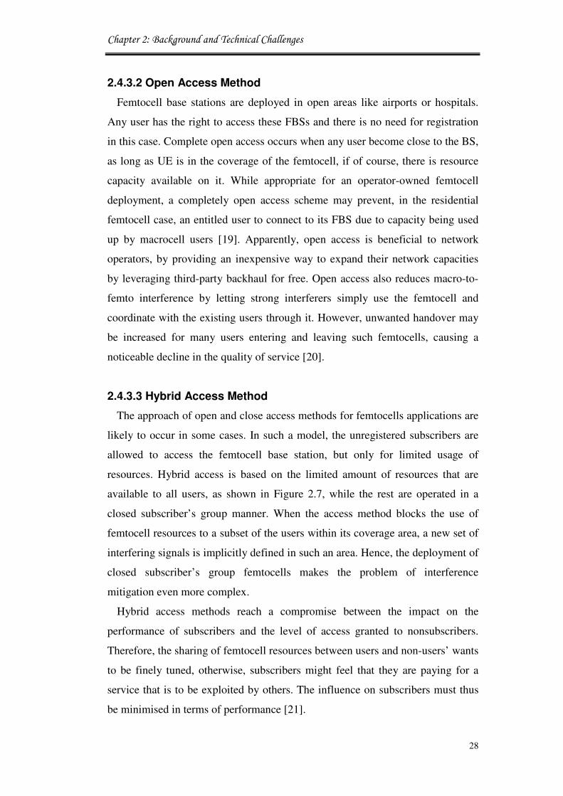
Chapter 2: Background and Technical Challenges
28
2.4.3.2 Open Access Method
Femtocell base stations are deployed in open areas like airports or hospitals.
Any user has the right to access these FBSs and there is no need for registration
in this case. Complete open access occurs when any user become close to the BS,
as long as UE is in the coverage of the femtocell, if of course, there is resource
capacity available on it. While appropriate for an operator-owned femtocell
deployment, a completely open access scheme may prevent, in the residential
femtocell case, an entitled user to connect to its FBS due to capacity being used
up by macrocell users [19]. Apparently, open access is beneficial to network
operators, by providing an inexpensive way to expand their network capacities
by leveraging third-party backhaul for free. Open access also reduces macro-to-
femto interference by letting strong interferers simply use the femtocell and
coordinate with the existing users through it. However, unwanted handover may
be increased for many users entering and leaving such femtocells, causing a
noticeable decline in the quality of service [20].
2.4.3.3 Hybrid Access Method
The approach of open and close access methods for femtocells applications are
likely to occur in some cases. In such a model, the unregistered subscribers are
allowed to access the femtocell base station, but only for limited usage of
resources. Hybrid access is based on the limited amount of resources that are
available to all users, as shown in Figure 2.7, while the rest are operated in a
closed subscriber’s group manner. When the access method blocks the use of
femtocell resources to a subset of the users within its coverage area, a new set of
interfering signals is implicitly defined in such an area. Hence, the deployment of
closed subscriber’s group femtocells makes the problem of interference
mitigation even more complex.
Hybrid access methods reach a compromise between the impact on the
performance of subscribers and the level of access granted to nonsubscribers.
Therefore, the sharing of femtocell resources between users and non-users’ wants
to be finely tuned, otherwise, subscribers might feel that they are paying for a
service that is to be exploited by others. The influence on subscribers must thus
be minimised in terms of performance [21].
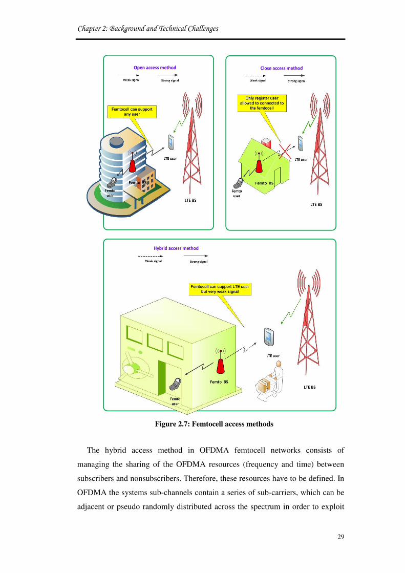
Chapter 2: Background and Technical Challenges
29
Figure 2.7: Femtocell access methods
The hybrid access method in OFDMA femtocell networks consists of
managing the sharing of the OFDMA resources (frequency and time) between
subscribers and nonsubscribers. Therefore, these resources have to be defined. In
OFDMA the systems sub-channels contain a series of sub-carriers, which can be
adjacent or pseudo randomly distributed across the spectrum in order to exploit
Chapter 2: Background and Technical Challenges
30
either multi-user or frequency diversity and the choice of either one or the other
channelisation mode depends on the accuracy of the channel state information
[22].
2.5 Cognitive Radio Technique
Cognitive radio network has recently emerged as a promising technique to
improve the utilisation of the existing radio spectrum. Cognitive radio is an
intelligent wireless communication system that is aware of its surrounding
environment, and uses the methodology of understanding-by-building to learn
from the environment and adapt its internal states to statistical variations in the
incoming radio frequency by making corresponding changes in certain operating
parameters (e.g., transmit power, carrier frequency, and modulation strategy) in
real-time, with two primary objectives in mind: (i) highly reliable
communication whenever and wherever needed and (ii) efficient utilisation of the
radio spectrum [23], as shown in Figure 2.8.
Figure 2.8: Spectrum opportunities for cognitive radio
A radio is adaptive when it can autonomously modify its operating parameters
in response to the characteristics of the environment in which it finds itself. For
instance, a radio that modifies Intermediate Frequency (IF) filter characteristics
in response to the characteristics of the channel it is using may be considered
adaptive. In other words, an adaptive radio must be able to make changes to its
operating parameters such as power level, modulation, frequency, etc. An
802.11a radio exhibits a level of adaptively as it is able to sense the Bit Error

Chapter 2: Background and Technical Challenges
31
Rate (BER) of its link and adapts the modulation to a data rate and a
corresponding Forward Error Correction (FEC) that sets the BER to an
acceptable level for data applications [24]. The different protocols in MAC,
networks, transport and application layers should be adaptive to the variation in
the CR environment. On the other side, a CR module is used to establish the
interfaces among the different layers and control the protocol parameters based
on intelligent algorithms [25].
The cognitive radio can be programmed to transmit and receive on a variety of
frequencies and to use different transmission access technologies supported by its
hardware design. Therefore, cognitive radio can offer a novel way of solving
spectrum underutilisation. It does so by sensing the radio environment with a
two-fold objective identifying those sub-bands of the radio spectrum that are
underutilised by the primary (i.e. legacy) users. However, in order to achieve
these goals in an autonomous manner, multiuser cognitive radio networks will
have to be self-organising.
2.5.1 Cognitive Networks Functions
Although there are many scenarios for the coexistence between primary and
secondary networks, it is mandatory to achieve a certain level of cooperation to
prevent any interference resulting from the contention between the cognitive and
primary networks or between the cognitive networks. This situation becomes
even more complicated in a heterogonous wireless environment composed of
many two types of networks primary and secondary. Thus, cooperative schemes
are necessary to guarantee seamless communications and to achieve optimal
spectrum access. The IEEE 802.11 networks perform the listen to talk operations
in transmissions. Therefore, they are the best available standards to simulate the
future cognitive network with zero inferences. However, there are several studies
about the differences between the traditional networks and the cognitive
capabilities and they have been reviewed in [26, 27].
The mental processes of a cognitive radio based on the cognition circle are
depicted in Figure 2.9. Cognition is illustrated at the example of flexible radio
spectrum usage and the consideration of user preferences. The ability of
cognitive radio of adapt and learn from past behavior is particularly important in

Chapter 2: Background and Technical Challenges
32
sight of the fact that understanding the interactions between layers is difficult.
However, there is a several protocol architectures incorporate adaptation, but
often no discussion is given to intelligence, learning, or pro-active adaptation.
Figure 2.9: Cognitive radio operations
2.5.1.1 Spectrum Sensing
A cognitive radio can sense spectrum and detect “spectrum holes” which are
those frequency bands that are not used by the licensed users or having limited
interference within them. Spectrum sensing can be performed in either
centralised or distributed ways. In centralised spectrum sensing, a central unit,
also called sensing controller, is in charge of the sensing process. The sensing
information is shared with the different secondary users using a control channel.
The cooperative spectrum sensing is more accurate and can reduce the primary
signal detection time [28].
2.5.1.2 Spectrum Sharing
Spectrum sharing techniques are generally focused on two types of solutions,
spectrum sharing inside a CR network (intra-network spectrum sharing), and
among multiple coexisting CR networks (inter-network spectrum sharing) [29].
Once a proper spectrum band is selected in spectrum decision, communication
channels in that spectrum needs to be assigned to a CR user while determining its
transmission power to avoid the interference to the primary network (resource
allocation). Then, the CR user decides when the spectrum should be accessed to

Chapter 2: Background and Technical Challenges
33
avoid collisions with other CR users (spectrum access).
A cognitive radio could incorporate a mechanism that would enable sharing of
spectrum under the terms of an agreement between a licensee and a third party.
This function picks up the appropriate MAC protocol to access the spectrum
holes. At the MAC layer protocol, the reasonable spectrum sharing between the
different users can be guaranteed. Additionally, management between base
stations can be achieved in order to avoid the collision with Primary User (PUs)
as well as with other Secondary User (SUs) pairs. This can be done by
negotiating the spectrum opportunities available to share them on an ad-hoc or
real-time basis, without the need for prior spectrum allocation between all users.
In a cooperative cognitive radio network, the primary users can lease their
spectrum to cognitive radio users for a portion of time and in exchange, they can
get the cooperative radio transmission power from the cognitive users. However,
the cognitive radio may have algorithms that can allow the sharing of spectrum
in terms of arranged agreements between a licenses network. Spectrum sharing
plays thereby a significant factor to increase spectrum utilisation.
2.5.1.3 Spectrum Decision
This function is able to analyse the information that comes from sensing the
spectrum. Before making the spectrum access decision, the characteristics of the
identified spectrum holes, the probability of the PU appearance and the possible
sensing errors should be measured. Once the suitable band is selected, the CR
has to optimise the available system resources in order to achieve the required
objective. CR networks require capabilities to decide on the best spectrum band
among the available bands according to the QoS requirements of the
applications. This idea is called spectrum decision and constitutes a rather
important but yet unexplored topic.
Spectrum decision is closely related to the channel characteristics and the
operations of primary users. Spectrum decision usually consists of two steps:
First, each spectrum band is characterised based on not only local observations of
CR users but also statistical information of primary networks. Then, based on
this characterisation, the most appropriate spectrum band can be chosen. In the
other words, the CR user finds the best spectrum band to satisfy user’s QoS

Chapter 2: Background and Technical Challenges
34
requirements (sustainable rate, delay, jitter, average session time, acceptable loss
rate, etc) and spectrum characteristics. CR users require spectrum decision at the
beginning of the transmission. Through RF observation, CR users characterise
available spectrum bands by considering the received signal strength,
interference, and the number of users currently residing in the spectrum, which
are also used for resource allocation in classical wireless networks [30, 31].
2.5.1.4 Location Identification
The ability to determine the spectrum users’ locations in order to identify the
appropriate operating parameters such as the power and frequency allowed at
surrounding locations is highly required. In bands such as those used for satellite
downlinks that are receive-only and do not transmit a data, location technology
may be an suitable technique for avoiding interference because sensing
knowledge would not be able to identify the locations of nearby receivers.
2.5.1.5 Network Discovery
For a cognitive radio terminal to determine the best way to communicate, it
should first learn about available access networks around it by long time
monitoring. These networks are reachable either via directed one hop
communication or via multi hop relay cognitive nodes. The capability to discover
one hop or multi hop located access networks is critical to secure dependable
connections.
2.6 Cognitive Network Management
Cognitive radio networks have different modes for managing the access to the
spectrum in order to share transmission opportunities between different users.
The functionality of such settings and decided by the level of expected
collaboration between users and many other technical features for the systems in
operation. Thus, a cognitive network may fall within one of three categories:
centralised, distributed, and hybrid managements.
2.6.1 Centralised Network Architecture
This mode of cognitive network employs a central entity namely Spectrum

Chapter 2: Background and Technical Challenges
35
broker which plays the essential role of managing the spectrum sharing resources
among different wireless generation networks. In this way, the centralised
spectrum broker is able to coordinate access to the spectrum in a given area and
allocates short term spectrum occupancies to competing wireless service
suppliers and end users, as shown in Figure 2.10.
Spectrum broker or server is a central network entity that plays a significant
character of spectrum sharing of the resources among wireless heterogeneous
networks. In spectrum broker technique [32] server has ability to connect to any
network and coexistence of primary and secondary radios in a shared
environment in a centralised fashion, local network level brokering mechanism
that targets to significantly increase spectrum utilisation while reducing the
complexity requirements of cognitive system deployment.
Figure 2.10: Centralised network management architecture

Chapter 2: Background and Technical Challenges
36
The centralized spectrum server can collate the information about surrounding
wireless environment and interference through local measurements from
different terminals and then provide offer suggestions to the efficient spectrum
use [33].
2.6.2 Distributed Network Architecture
The most common controlling application for cognitive networks assumes the
absence of a centralised management infrastructure. This mode of service
management namely as distributed management deals with different self-
management techniques that are able to decide to access the spectrum in a
distributed way, as shown in Figure 2.11.
Figure 2.11: Distributed network architecture

Chapter 2: Background and Technical Challenges
37
Therefore, strategy services for considering dynamic network environments
must be adaptive to different operational environments and resource availability.
Motivated by this requirement and by previous research in network management
[34] and [35] consequently, each cognitive node has the ability to allocate the
spectrum opportunities according to local strategies. This spectrum allocation
policy is performed based on local negotiating between cognitive nodes in the
local area [36]. Thus, local self- organised groups negotiate the assigning of the
spectrum holes to any end-users equipment within their groups and surrounding
nodes before making final adaptations.
The control process for resource allocation of cognitive networks is performed
by the spectrum management entity in the base station node. This entity shares
the information which has been collected from both local observation and
cooperative sensing to determine where unlicensed users can access the free
spectrum on individual basis [37]. In order to transmit in a distributed system, the
cognitive node initially starts to broadcast a request to its neighbours within the
same domain to avoid any interference. Neighbours are started to join the group
and reply to the requester from a coordination or senior cognitive node. The
group senior node will be the responsible to decide upon final allocation of the
transmission request and informing other neighbours’ nodes. The cognitive nodes
can exchange information and coordination messages by using a dedicated
Common Spectrum Control Channel (CSCC) with higher power and hence larger
transmission range via multi-hop routing. In fact, the most probable scenario for
a spectrum conflict may occur when two cognitive nodes are willing to transmit
at the same time provided by the long-time consumed for issuing a transmission
request [38] and [39].
2.6.3 Hybrid Network Architecture
In this management approach the centralised and distributed models are
bridged to create a hybrid spectrum sharing system. The spectrum broker will be
the main spectrum governing entity for issuing transmission requites from groups
whenever a conflict in accessing the spectrum emerges between neighboured
different groups’ nodes, as shown in Figure 2.12.
On the other hand, the spectrum access management inside the groups is

Chapter 2: Background and Technical Challenges
38
performed using the distributed model. This means that groups’ senior node is
the main decision maker for accessing the spectrum in their groups provided by
being the contact node with the spectrum broker. The CSCC is used for
exchanging the spectrum arrangements for local groups and between the group’s’
senior node and the spectrum broker. The senior node is chosen by the groups’
radios for its long experience and operation in the wireless local area due to
negotiations between all group nodes. The main advantage of this model is to
allow the spectrum broker to deal with other operators’ requests and to reduce
the information’s exchanged over the CSCC [40].
Figure 2.12: Hybrid network architecture
2.7 Cognitive Femtocell in LTE Systems
Cognitive radio interconnection of femtocell networks could be part of future
Internet wireless networks. This new coexistence paradigm between cognitive

Chapter 2: Background and Technical Challenges
39
radio and femtocells is based on predefined converge areas of services and the
challenge is to combine the capacity of different resources to provide broadband
access to both stationary and mobile cognitive users. However, high throughput
demands of mobile end users in the future may need more resources than what
are currently available for the exiting macrocell networks. Hence, femtocell
networks will play a vital role in supporting indoor environments, such as
airports, hospitals, or houses. Enhancing data delivery for Internet services could
be creating a novel cross layer framework in the gateway router. This improves
the cognitive femtocells’ flexibility and efficiency in accessing the spectrum. On
the other hand, the new design concepts increase system’s reconfigurability to
respond to real-time changes in the wireless environment [18].
In this research, two-tier networks are considered that consist of overlaying
macrocell and cognitive femtocell systems. Within the overlapped coverage areas
in such a two-tier system, an User Equipment (UE) has the option to access
either macrocell base station or femtocell base station, and it can switch the
access tier by performing seamless vertical handover. In this thesis, a user
accessing a macrocell BS is called UE, and a user accessed to a femtocell BS is
called Femtocell Users Equipment FUE. After obtaining licensed spectrum,
wireless cellular operator can adopt different approaches to utilise the spectrum
in a wireless overlay network. The principal approach is that two tier networks
share the licensed spectrum, such that macrocell and femtocell operate in co-
channel frequency reuse. This approach is called spectrum efficiency usage.
Other aspects are focusing on resource management to avoid two-tier
interference where each radio tier has a more available aggregate of spectrum but
suffers higher cross-tier interference. On the other hand, this work will go further
in examining the possibility of relay enhanced networks, measuring the potential
increase in energy efficiency that deploying a certain number of low powered
relay femtocell nodes can provide.
The investigations in the possible energy savings that are possible for cognitive
mobile networks by using new framework vision for green management network
are considered, as shown in Figure 2.13. This energy saving are obtained by
presenting a feature that dynamically places low loaded cells into sleep mode,
during which radio circuits are efficiently powered down, decreasing the

Chapter 2: Background and Technical Challenges
40
networks’ energy consumption. The main goal of the whole design is to
maximise the achievable throughput of the system while minimising the need of
cognitive femtocell for the power. In addition, the work has investigated the
effect of the deployment of a cognitive femtocell network within the LTE system
transmission. The femtocell scheme approved by 3GPP for LTE is implemented
and its performance evaluation is investigated in this thesis.
Energy efficient enhancement in wireless communication can be achieved only
if improvements are experienced in the whole communication chain for different
operational load scenarios. Similarly, the multi-user scheduler should indeed
allocate time and frequency resources to minimise the transmission energy cost
while meeting QoS requirements of all active users admitted by a base station.
The momentary system load plays an important role in the overall optimisation
design. Currently deployed base stations are commonly designed so that they can
accommodate the traffic demand at peak times. Nevertheless, cell traffic load
notably varies during the day. Several researches pointed out that to save energy,
base stations should perform a dynamic load and energy state arrangement,
which balances extra load on a determined optimal set of base stations, thus
maintaining minimum energy consumption [41].
Figure 2.13: Framework for green network management

Chapter 2: Background and Technical Challenges
41
2.8 Technical Challenges
The following sections indicate the key technical challenges facing functional
deployments of femtocell network systems.
2.8.1 Spectrum Decision and Allocation Efficiency
Channel management in the femtocell networks is one of the main features that
represent a radical departure from the existing mobile networks. The spectrum
technology deployment is growing faster than the determination in spectrum
availability. Therefore, as frequency bands or free white holes become more
scarce and unavailable for the next generation wireless technologies then a wide
range of services will require radio spectrum as a resource to operate properly.
This leads to the important investigation of the spectrum efficient utilisation. In
the development of the spectrum decision function, several challenges still
remain unsolved [31]:
• Decision model: Spectrum capacity estimation using Signal-to-Noise
Ratio (SNR) is not sufficient to characterise the spectrum band in CR
networks. Applications require different QoS requirements, thus, the
design of spectrum decision function base on spectrum adaptive, and
spectrum decision models is still a research issue.
• Cooperation with reconfiguration: CR techniques enable transmission
parameters to be reconfigured for optimal operation in a certain
spectrum band. For example, even if SNR is changed, bit rate and BER
can be maintained by exploiting adaptive modulation instead of
spectrum decision. Hence, a cooperative framework with
reconfiguration is required in the spectrum decision.
• Spectrum decision over heterogeneous spectrum bands: Currently,
certain spectrum bands are assigned to different purposes, whereas
some bands remain unlicensed. Thus, a CR network should support
spectrum decision operations on both the licensed and unlicensed
bands.

Chapter 2: Background and Technical Challenges
42
However, the dedicated channel deployment may not be applicable when
femtocells are densely deployed. As a consequence, it may be practical to make
macrocell and femtocells share the available spectrum together. Co-channel
operation of macrocell and femtocells was considered by dynamically adjusting
the transmit power [42]. Assigning orthogonal spectrum resources between the
central macrocell and femtocell BSs eliminates cross-tier interference [43]. The
orthogonal access spectrum allocation strategy is illustrated in Figure 2.14.
To avoid persistent collisions with neighbouring femtocells in accessing the
spectrum, each femtocell can access a random subset of the candidate frequency
sub-channels, where each sub-channel is accessed with equal probability. Mobile
operators can deploy femtocell base stations that operate on a cross channel or a
co-channel basis with existing macrocell. While operating on a dedicated channel
is a pragmatic strategy, co-channel operation also has benefits due to the
potentially increased spectral efficiency using spatial frequency re-use. On the
other hand, co-channel operation may cause more interference between BSs.
Shared spectrum operation may be desirable to operators because of the scarce
availability of spectrum and flexibility during deployment [44] with shared
spectrum between tiers. However, radio interference between cellular users and
femtocell hotspots, and between hotspot users and the macrocell BS, is likely to
be the capacity-limiting factor.
Figure 2.14: Spectrum sub-channels division

Chapter 2: Background and Technical Challenges
43
2.8.2 Providing QoS Awareness over an Internet Backhaul
Allocated and distributed nature of FBSs raises many technical challenges for
the increasing requirements of multimedia applications, and this requires more
management over the systems accessible resources.
To decide on an appropriate spectrum band, cognitive radio networks should
support QoS-aware communication, considering dynamic and heterogeneous
spectrum environment. Femtocell can interface with wireless communication
system without any requirements for installing additional equipment’s in wireless
communication networks because of using a Radio Network Controller (RNC).
Mobile Internet Protocol Television (IPTV) technology for mobile
telecommunications has been developed which is a representative service of
broadcasting and telecommunications convergence as shown in Figure 2.15.
´Mobile IPTV´ will be important service of International Mobile
Telecommunications-Advanced (IMT-Advanced) system. Therefore, the work
should be performed towards developing core technologies for cellular network
based ´Mobile IPTV´ and personal IP wireless broadcasting systems. Internet
Protocol (IP) backhaul needs QoS for delay-sensitive traffic and providing
service parity with macrocells. Additionally, it should provide sufficient capacity
to avoid creating a traffic bottleneck. While existing macrocell networks provide
latency guarantees within 15ms, current backhaul networks are not equipped to
provide delay resiliency [45].
Figure 2.15: Mobile (IPTV) technologies for next-generation systems

Chapter 2: Background and Technical Challenges
44
Lack of network objectivity poses a serious concern, except in the scenarios
where the wire backhaul provider is the same firm or in a tight strategic
relationship with the cellular operator.
2.8.3 Resource Management and Network Planning
Resource management is one of the most important functions in the cognitive
femtocell network because the system relies on it to guarantee a certain target
QoS, maintain the planned coverage area, and at the same time offer high network
capacity. The control procedures for radio resource management in networks with
femtocells should manage radio resources despite the limited backbone capacity.
To achieve an effective utilisation of backbone capacity, new scenarios will be
needed for data routing among users served by the same FBSs [46]. These
objectives often tend to be contradictory, for example QoS levels may be increased
at the expense of coverage or capacity reductions and vice versa. The key challenge
to improving spectrum utilisation, by handling cognitive femtocell users to
enable access to the spectrum dynamically without disturbing PUs, is resource
management which must have an efficient MAC mechanism that can efficiently
and adaptively allocate transmission powers and spectrum bands among CR
users based on surrounding environments. Besides routing, spectrum-efficient
techniques for power control, scheduling and broadcast services transmission are
needed. Additionally, novel user admission policies and FBSs identification
techniques are necessary in the new system with escalating numbers of users.
Network planning and resource management need to cooperate with each other in
order to meet the above requirements to efficiently use scarce radio resources. The
network planning aiming to tune these elements statically at a high level, radio
resource management within FBSs will need to provide efficient and effective
adjustment mechanisms to dynamically balance these restrictions as the surrounding
environment changes.
2.8.4 Interference Optimisation Problem
One of the most important challenges is the interference. In general, the
interferences occur among network elements that belong to the different tiers of the
network, i.e., interference between femtocells and macrocells. However, there are

Chapter 2: Background and Technical Challenges
45
two kinds of interference in femtocell communication networks; the first one is
called cross-layer interference that interference occur between femtocell and
macrocell and the other one is called co-layer interference that occur between
femtocell and others femtocells which is deployed in the coverage of the main
macrocell [47].
For example, femtocell UEs and macrocell UEs act as a source of uplink cross-tier
interference to the serving macrocell base station and the nearby femtocells,
respectively. On the other hand, the serving macrocell base station and
femtocells cause downlink cross-tier interference to the femtocell UEs and
nearby macrocell UEs, respectively. Again, in OFDMA-based femtocell
networks, cross-tier uplink or downlink interference occurs only when the same
sub-channels are used by the aggressor and the victim [48].
However, this approach requires a higher spectral efficiency because both tiers
access all resources. Nevertheless, in such configuration, cross-tier interference
occurs, which could degrade the overall network performance unless interference
is efficiently handled.
Figure 2.16: Macrocell downlink interference to the femtocell user

Chapter 2: Background and Technical Challenges
46
As shown in Figure 2.16, the Downlink Dedicated Physical Channel (DL-
DPCH) interference from macrocell operating co-channel to femtocell can be
modelled as the ratio of the received DL-DPCH power to interference from the
femtocell loading and interference from the co-channel macrocell base station.
The strong interference in the downlink (DL) from the macrocell should be well
organised to satisfy the QoS requirements of both femtocell users and macrocell
users. Interference problems could occur by macrocell base station DL connected
to a far femtocell mobile user which may subsequently be jammed due to the
presence of a closer DL femtocell user who is using the same frequency/time.
On the other hand, Up Link (UL) mobile user connected to a macrocell could
be jammed due to the attendance of a close UL user connected to a femtocell
using the same frequency/time, as shown in Figure 2.17. Therefore, the
interference management techniques are essential to reduce the impact of
femtocell on the macrocell [49].
Figure 2.17: Downlink interference in LTE-femtocell OFDM co-channel
Example: Consider an OFDM reverse link with parameters:
• Distance of macrocell user to macrocell= 500meters
• Distance of macrocell user to femtocell= 30meters
• Femtocell radius= 40meters
• Processing gain=128dB
• Path-loss exponent= 4dB
Chapter 2: Background and Technical Challenges
47
• Desired receive power= 0dBm (1mW)
Interference power from user at femtocell:
= 10 ∗ log�� �500�
30� � = 4887dB(2.4)
OFDM Interference suppression:
= 10 ∗ log��(128) = 21.07dB(2.5)
Signal-to-Interference Ratio at femtocell = -27.8 dB
In this scenario the macrocell user is connected to the macrocell base station at
the cell edge. This user is located in the same FBS zone where no access is
allowed. The macrocell user is thus interfered in the downlink by the fully loaded
FBS. The best solution for this case is that the procedure of an adaptive power
control is required to maintain capacity, which can benefit from an increase of up
to 16%.
2.8.5 Mobility Problems
Handover from femtocell to macrocell is more complicated in the reverse case.
Therefore, seamless handover between macrocell BSs and femtocell systems as
well as between FBS should be supported, but at ordinary speeds. Cognitive
femtocell users are a temporally visitors to the spectrum. Therefore, if the
specific sector of the spectrum that is in use is required by a LTE user, the
communication needs to be continued in another vacant portion of the spectrum.
Furthermore, for the abovementioned system requirements, there is an
expectation that the LTE air interface will provide further optimisation for
femtocell operation. For example:
• Signal measurement report to support advanced interference management,
radio resource management, and femtocells location.
Chapter 2: Background and Technical Challenges
48
• Optimisation of UEs scanning, selection, network entry, and handover to
the desired BSs in multilayer networks consisting of macrocell BSs and
large numbers of femtocell BSs. These features would further optimise
femtocell operations and facilitate their usage [50]. Mobile users should be
able to select a proper operating network so that corresponding access can
be employed. Handover issues among the cognitive femtocell networks can
also be considered in the scope of cell selection.
The mobility management may captures the best available channel, primary
user activity on the selected spectrum may necessitate that the user changes its
operating spectrum band(s), which is referred to as spectrum mobility. Each time
a CR user changes its frequency, the network protocols may require
modifications to the operation parameters. The purpose of the spectrum mobility
management is to ensure smooth and fast transition leading to minimum
performance degradation during a spectrum handover. An important requirement
of mobility management protocols is information about the duration of a
spectrum handover. This information can be provided by the sensing algorithm.
After the latency information is available, the ongoing communications can be
preserved with only minimum performance degradation [31].
2.8.6 Self-Organisation and Power Efficiency Challenges
Efforts to increase the energy efficiency of information and communication
systems in mobile radio networks have recently gained a lot of attention. Besides
reducing the carbon footprint of the industry, there is a strong economic
incentive for network operators to reduce the energy consumption of their
systems. Currently over 80% of the power in mobile telecommunications is
consumed in the radio access network, more specifically the base stations [51].
Improvements can, in principle, be achieved in three ways: Firstly, reducing the
power consumption of base station either by using more power efficient
hardware or by using new advanced software to adjust power consumption to the
traffic situation based on the mobile distance. Secondly, by optimisation of
individual sites, through the use of more efficient and load adaptive hardware
components as well as software modules. Thirdly, by using intelligent network

Chapter 2: Background and Technical Challenges
49
deployment strategies, effectively lowering the number of sites requisite in the
network to achieve certain performance metrics such as spectral efficiency
coverage. To allow adaptation to changes in the network environment (i.e.,
configuration and properties of neighbouring macrocells/femtocells) an ongoing
measurement and self-optimisation process is performed to adapt parameters
such as scrambling code, pilot power and maximum data transmit power, sleep
mode technique and power saving. This ensures minimal impact on the macro-
cellular network and ensures that femtocell performance is maximised under the
given constraints.
To avoid high operating costs and redundant power consumption, femtocell
should support plug-and-play and implementable self-configuration and self-
optimisation algorithms. In addition, the numbers of sites per square kilometer
act with respect to inverse of the range. That may generate a lot of load on the
energy consumption for a small coverage area [52].
2.9 Conclusion
The evolution of the cellular and wireless networks is leading to a multi-
technology, multi-terminal, multi-application, and heterogeneous wireless
environment that is representing the 4G wireless networks. The basic architecture
of the main cellular and wireless technologies is described in detail. The chapter
also introduced the technical background of femtocell techniques and
deployment issues. There are numerous challenges that will require to be
addressed by the service provider in order to make the femtocell able to impact
on subscribers in terms of improving the spectrum efficiency performance. The
main challenges were described to enable a clear view for the main requirements
of the 4G wireless technology.
In order to achieve seamless connectivity within the heterogeneous wireless
environment an efficient mobility management is needed. From a technical
viewpoint, the main focus of this thesis is to design and implement network
management algorithms for improving cognitive femtocell coexistence in two-
tier networks.

Chapter 2: Background and Technical Challenges
50
2.10 References
[1] J. Govil, “4G Mobile Communication Systems: Turns, Trends and
Transition,” In Proc. of the IEEE International Conference on
Convergence Information Technology (ICCIT), Korea, November 2007,
pp. 13 - 18.
[2] D. Amzallag, R. Bar-Yehuda, D. Raz, and G. Scalosub, “Cell Selection in
4G Cellular Networks,” In Proc. of the 27th
IEEE Conference on Computer
Communications (INFOCOM), USA, March 2008, PP. 1 - 9.
[3] V. Chandrasekhar, J. G. Andrews, and A. Gatherer, “Femtocell Networks:
A Survey,” IEEE Communications Magazine, vol. 46, no. 9, pp. 59 - 67,
September 2008.
[4] D. Knisely, T. Yoshizawa, and F. Favichia, “Standardization of Femtocells
in 3GPP2,” IEEE Communications Magazine, vol. 47, no. 9, pp.76 - 82,
September 2009.
[5] V. Chandrasekhar, “Coexistence in Femtocell aided Cellular Architectures,”
PhD Dissertation, Department of Electrical and Computer Engineering,
University of Texas at Austin, May 2009.
[6] D. Knisely, “Femtocell Standardization,” White Paper, Airvana, USA, May
2010.
[7] S. Parkvall, E. Dahlman, A. Furuskär, Y. Jading, M. Olsson, S. Wänstedt,
K. Zangi, “LTE-Advanced Evolving LTE towards IMT-Advanced”,
Ericsson Research, 2008.
[8] 4G Americas, “Mobile Broadband Explosion,” Rysavy Research, pp. 1 -
144, August 2012.
[9] K. Zheng, B. Fan, J. Liu, Y. Lin, and W. WANG,“ Interference
Coordination for OFDM-Based Multihop LTE-Advanced Networks,” IEEE
Wireless Communication, vol. 18, no. 1, pp. 54 - 63, February 2011.
[10] T. Thanabalasingham, “Resource Allocation in OFDM Cellular Networks,”
PhD thesis, Department of Electrical and Electronic Engineering¸ the
University of Melbourne, 2006.
[11] J. Zyren and W. McCoy, “Overview of the 3GPP Long Term Evolution
Physical Layer,” White Paper, LTD Free Scale Semiconductor, July 2007.

Chapter 2: Background and Technical Challenges
51
[12] D. Perez, A. Valcarce, G. Roche, and J. Zhang, “OFDMA Femtocells: A
Roadmap on Interference Avoidance,” IEEE Communications Magazine,
vol. 47, no. 9, pp. 41- 48, September 2009.
[13] Y. Sang, H. Hwang and K. Kim, “A Self-Organized Femtocell for IEEE
802.16E System,” In proc. of the IEEE Global Telecommunications
Conference, Hawaii, USA, 2009.
[14] S. Das, P. Chandhar, S. Mitra, and P. Ghosh, “Issues in Femtocell
Deployment in Broadband OFDMA Networks: 3GPP–LTE a case study,”
In Proc. of the 74th
IEEE Vehicular Technology Conference (VTC Fall),
San Francisco, United States, 2011, pp. 1 - 5.
[15] 3GPP, “Further advancements for Ultra physical layer aspects”, Technical
Report, TR.36.814, 2010.
[16] K. Sung, H. Haas, and S. McLaughlin, “A Semianalytical PDF of Downlink
SINR for Femtocell Networks,” EURASIP Journal on Wireless
Communications and Networking, vol. 2010, Article ID 256370, pp. 1 - 9,
2010.
[17] T. Watanabe, H. Ohyan, N. Nakaminami, and Y. Hiramoto, “Super
Compact Base Station Femtocells,” NNT DOCOCM Technical Journal,
vol. 10 no. 2, pp. 64 - 68, 2008.
[18] S. Al-Rubaye, A. Al-Dulaimi and J. Cosmas, “Cognitive Femtocells: Future
Wireless Networks for Indoor Applications,” IEEE Vehicular Technology
Magazine, vol. 6, no. 1, pp. 44 - 51, 2011.
[19] D. Das and V. Ramaswamy, “Co-channel Femtocell-Macrocell
Deployments Access Control,” In Proc. of the IEEE conference of
Vehicular Technology, Chelmsford, MA, USA, 2009.
[20] P. Xia, V. Chandrasekhar, and J. Andrews, “Open vs. Closed Access
Femtocells in the Uplink,” IEEE Transactions on Wireless
Communications, vol. 9, no. 12, pp. 3798 - 3809, December 2010.
[21] G. Roche, A. Valcarce, D. López-Pérez, and J. Zhang, “Access Control
Mechanisms for Femtocells,” IEEE Communications Magazine, vol. 48,
no.1, pp33 - 38, 2010.

Chapter 2: Background and Technical Challenges
52
[22] ICT- 248891 STP FREEDOM, “Femtocell-based network enhancement by
interference management and coordination of information for seamless
connectivity,” Report, May 2010.
[23] S. Haykin and S. Soliman, “Cognitive radio: Brain-empowered wireless
communications,” IEEE Journal Select. Areas Communication, vol. 23, no.
2, pp. 201 - 220, February 2005.
[24] B. Fette, Cognitive Radio Technology, Second Edition, pp. 132 - 135,
Elsevier Inc., Oxford, UK, 2006.
[25] E. Hossain, D. Niyato, and Z. Han, Dynamic Spectrum Access and
Management in Cognitive Radio Networks, Cambridge University Press,
New York, NY, USA, 2009.
[26] S. Al-Rubaye, A. Al-Dulaimi, L. AL-Saeed, H. Al-Raweshidy, E. Kadhum,
and Widad Ismail, “Development of Heterogeneous Cognitive Radio and
Wireless Access Network,” in Proc. 24th
Wireless World Research Forum
(WWRF), Penang Island, Malaysia, April 2010.
[27] K. Chen, Y. Peng, N. Prasad, Y. Liang, and S. Sun, “Cognitive Radio
Network Architecture: part I - General Structure,” In Proc. of the IEEE 2nd
International Conference on Ubiquitous Information Management and
Communication, Suwon, Korea, 2008.
[28] G. Ganesan and Y. Li, “Cooperative spectrum sensing in cognitive radio,
part I: Two user networks,” IEEE Transactions on Wireless
Communications, vol. 6, no. 6, pp. 2204 - 2213, June 2007.
[29] I. Akyildiz, W. Lee, M. Vuran, and S. Mohanty, “Next Generation/
Dynamic Spectrum Access /Cognitive Radio Wireless Networks: A
Survey,” Computer Networks Journal (Elsevier), vol. 50, pp. 2127 - 2159,
September 2006.
[30] Q. Wang and H. Zheng, “Route and spectrum selection in dynamic
spectrum network stations,” in Proc. of the IEEE Consumer
Communications and Networking Conference (CNCC), Nevada, USA,
2006.
[31] I. F. Akyildiz, W. Y. Lee, M. C. Vuran, and S. Mohanty, “Survey on
Spectrum Management in Cognitive Radio Networks,” IEEE
Communications Magazine, vol. 46, no. 4, pp. 40 - 48, 2008.

Chapter 2: Background and Technical Challenges
53
[32] A. Ghasemi and A. S. Sousa, “Spectrum Sensing in Cognitive Radio
Networks: Requirements, Challenges and Design Trade-offs,” IEEE
Communications Magazine, vol. 46, no.4, pp. 32 - 39, April 2008.
[33] K. Richardson, “A Study into Dynamic Spectrum Access,” OFCOM Final
Report, no.1, pp. 1 -186, March 2007.
[34] M. Sloman, “Policy driven management for distributed systems,” Journal
of Network and Systems Management, vol. 2, no. 4, pp. 333 - 360, 1994.
[35] R. W. Lucky, “Reflections: Where Is the Vision for Telecom?,” IEEE
Spectrum Journal, vol. 41, no.5, pp. 72, May 2004.
[36] W. Lee and I. F. Akyildiz, “Spectrum Decision Framework for Cognitive
Radio Networks,” IEEE Transactions on Mobile Computing, vol. 10, no. 2,
pp 161 - 174, February 2011.
[37] L. Cao and H. Zheng, “Distributed spectrum allocation via local
bargaining,” in Proc. of the IEEE Sensor and Ad Hoc Communications and
Networks (SECON) 2005, Santa Clara, California, USA ,September 2005,
pp. 475 - 486.
[38] M. Buddhikot and K. Ryan, “Spectrum management in coordinated
dynamic spectrum access based cellular networks,” In Proc. of the IEEE
Dynamic Spectrum Access Networks (DySPAN), Maryland, USA,
November 2005, pp. 299 - 307.
[39] A. Agustin, J. Vidal, O. Muñoz-Medina, and J. R. Fonollosa, “Decentralized
Weighted Sum Rate Maximization in MIMO-OFDMA Femtocell
Networks,” in Proc. of the IEEE Global Communications Conference and
Workshop on Femtocell Networks (GLOBECOM), in Houston, Texas,
USA, 2011.
[40] A. Al-Dulaimi and H. S. Al-Raweshidy, “Multi-Operator Cognitive Radios
Sharing One Channel,” In Proc. of the 7th
ACM international symposium
on Mobility Management and Wireless Access (MobiWac’09), Tenerife,
Spain, 2009, pp. 114 - 117.
[41] E. C. Strinati, A. D. Domenico and L. Herault, “Green Communications: an
Emerging Challenge for Mobile Broadband Communication Networks,”
Journal of Green Engineering, vol. 3, no. 1, pp. 267 - 301, 2011.

Chapter 2: Background and Technical Challenges
54
[42] D. Oh, H. Lee, and Y. Lee, “Cognitive Radio Based Cognitive radio based
femtocell resource allocation,” in Proc. of the IEEE International
Conference on Information and Communication Technology Convergence
(ICTC), Korea, 2010.
[43] V. Chandrasekhar and J. Andrews, “Spectrum allocation in two-tier
femtocell networks,” in Proc. of the IEEE Conference Signals, Systems and
Computers, Pacific Grove, CA, 2008.
[44] L. Ho and H. Claussen, “Effects of user-deployed, co-channel femtocells
on the call drop probability in a residential scenario,” In Proc. of the IEEE
International Symposium on Personal, Indoor and Mobile Radio
Communications, Athens, Greece, 2007, pp. 1 - 5.
[45] Anritsu company, “Future Technologies and Testing for Fixed Mobile
Convergence SAE and LTE in Cellular Mobile Communication,” White
Paper, October 2010.
[46] G. Vivier, M. kamoun, Z. Becvar, E. Marinis, Y. Lostanlen, and A.
Widiawan, “Femtocells for next-G Wireless Systems: the FREEDOM
approach,” In Proc. of the Conference Future Network & Mobile Summit
International Information Management Corporation, Florence, Italy, 2010,
pp. 1 - 9.
[47] A. Zyoud, M. H. Habaebi, J. Chebil and M. R. Islam, “Femtocell
Interference Mitigation,” In Proc. of the IEEE Conference Control and
System Graduate Research Colloquium (ICSGRC 2012), Kuala Lumpur,
Malaysia, July 2012.
[48] N. Saquib, E. Hossain, L. Le, and D. Kim, “Interference management in
OFDMA femtocell networks: Issues and approaches,” IEEE Wireless
Communications, vol. 19, no. 3, pp. 86 - 95, June 2012.
[49] D. López-Pérez, G. De La Roche, A. Valcarce, A. Jüttner, J. Zhang,
“Interference Avoidance and Dynamic Frequency Planning for WiMAX
Femtocells Networks,” In Proc. of the IEEE International Conference on
Communication Systems (ICCS), Guangzhou, China, November 2008.
[50] R. Kim, J. Kwak, and K. Etemad, “WiMAX Femtocell: Requirements,
Challenges, and Solutions”, IEEE Communications Magazine, vol. 47, no.
9, pp. 84 - 91, September 2009.
Chapter 2: Background and Technical Challenges
55
[51] G. Fettweis and E. Zimmermann, “ICT energy consumption trends and
challenges,” In Proc. of the 11th
International Symposium on Wireless
Personal Multimedia Communications, Lapland, Finland, 2008.
[52] I. Koutsopoulos, and L. Tassiulas, “The Impact of Space Division
Multiplexing on Resource Allocation: A Unified Treatment of TDMA,
OFDMA and CDMA,” IEEE Transactions on Communications, vol. 56,
no. 2, pp. 1 - 10, February 2008.

Chapter 3: Spectrum Management
56
Chapter 3Chapter 3Chapter 3Chapter 3
Spectrum Management in
Cognitive Radio Systems
The spectrum coordination of cognitive networks is a major challenge in
large/small domains to achieve an efficient resource allocation and to meet the
QoS requirements of different traffic downloading requests. In this regards, a
novel spectrum management model is proposed for resource allocation, spectrum
sensing, and spectrum decision making. Primary and cognitive networks are
considered to coexist with each other under dynamic spectrum wireless access to
validate the given solution. The cognitive network uses 802.11e technology that
allows cognitive users to identify and access the available frequency spectrum
without interfering primary users. Then, a novel solution for LTE-femtocell
resource management is investigated with new algorithms that are able to capture
the key parameters of spectrum access prioritisation as a function of the available
free transmission channels. The spectrum management model is integrated into
PHY and MAC layers of the cognitive radio system to enable the user to
communicate reliably between LTE and femtocell networks.

Chapter 3: Spectrum Management
57
3.1 Introduction
Cognitive Femtocell System (CFSs) is an emerging technology in the next
generation networks to ensure active coverage and higher throughput for small
range communications. However, it is necessary to manage the quality of service
for the reason of limited network resources available to access. In addition, the
assignment of resources among an increasing number of consumers requires
scheduling services and time slot management for each spectrum channel
available [1]. Thus, the solution relies on using cognitive femtocell radio as the
femtocell technology to exploit the spectrum efficiency in coexistence with LTE
macrocellular system in a realistic scenarios and networks.
Figure 3.1: Spectrum management architecture for cognitive radio networks
In this spectrum management model the QoS requirements are adjusted
according to the spectrum availability in order to create traffic queues that
support different types of applications with similar QoS requirements.
Chapter 3: Spectrum Management
58
Accordingly, transmission decisions are made to send the long traffic packets in
advance of other applications whenever there is a channel space available for
such actions. The proposed spectrum management architecture can be mainly
classified into two parts: decision making and spectrum sensing as shown in
Figure 3.1.
The obvious advantage to the cognitive radios and the closely related
technologies is not just spectrum efficiency but also moving towards a policy-
based adaptive radio. To apply this, it is necessary for these developed radios to
be controlled in such a way that underutilised portions of the spectrum can be
utilised more efficiently. This is called as opportunistic spectrum management
and it is supported by transmission policies. The network control of these
advanced radios includes control of the configuration of the radio and the RF
operating parameters. Regulatory policies which govern the allowable behaviour,
i.e., RF operating parameters, are part of this network control. The control
policies may, for some scenarios, also include network operator and user policies
[2].
In this chapter, a novel spectrum resource management system is proposed to
allocate the available spectrum efficiently using new algorithms and modules.
The main theme of this chapter is to combine the capacity of different resources
to provide good broadband access to both stationary and mobile cognitive users.
However, high throughput demands for mobile end users in the future may need
more resources than what are currently available for the existing macrocell
networks. The important contribution in the proposed systems with respect to
existing literature is the analysis of spectrum occupancy over different sub-bands
of the channel’s environment. To our knowledge, there is no other model
technique that takes account of all these parameters into one model.
3.2 Related work
The dynamic spectrum and resource management optimisation methodology
aims to provide a communication network with higher capacity using many
techniques. The dynamic spectrum sharing model in [3] is aiming to maximise
the total throughput of both primary users and secondary users at the same time.
The problem is formulated in two approaches for allocating channels to primary

Chapter 3: Spectrum Management
59
users with fixed allocation and random allocation. In the fixed allocation
approach, the fixed channel is located for a number of primary users all the time,
with different number of mobile users in different channels. In the random
spectrum allocation approach, the primary user has a priority to access the
spectrum at any time dynamically and randomly in each time [4].
The authors in [5] have addressed the downlink spectrum sharing challenges in
cognitive radio femtocell as a mixed integer, nonlinear programming problem,
and used decomposition methods to solve this problem. The new solution
involved a cooperative channel allocation and an adaptive power control
approach to improve spectrum access and cognitive service delivery. On other
hand, an optimised spectrum resource management for a cognitive LTE network
with femtocell is proposed in [6]. Here, the base station and users are equipped
with CRs and can intelligently adjust power, frequency, and other features to
allow the spectrum requests of the entire network system. The design is based on
stochastic optimisation in order to take advantage of the cognitive radio technical
flexibility and ability to utilise the spectrum.
The approach in [7] proposed a Cognitive Resource Management (CRM) for
cognitive femtocells that can autonomously adapt the radio resource usage to
avoid any interference with the macrocell station. The effective capacity of the
CRM that specifies a QoS guarantee capability for the system was analytically
derived. The CRM identifies an optimum sensing period to achieve radio
resource utilisation for a certain QoS profile. Moreover, a cooperative radio
resource management to investigate the multiple cognitive radio networks in
interference environments was proposed by [8]. The aim of this research was to
achieve shared radio resources fairly among multiple non cooperative cognitive
radio networks in order to improve the overall network performance. The main
goal of this research was to achieve information sharing and decision distribution
between CR networks in a distributed approach.
Prior research has been focusing mainly on framework management function.
Scheduling for wireless networks has brought a lot of research attention that
mostly includes centralised and distributed architecture approaches [9, 10].
Centralised scheduling algorithms were proposed based on chart method by
assuming that a central controller has full awareness about on the network. The

Chapter 3: Spectrum Management
60
technique finds the best set of non-overlapping links with increasing the total
throughput in overall system. Investigators, meanwhile, have been considering a
two-layer design for QoS in wired and wireless networks. The authors in [11, 12]
have addressed extensively a QoS solution to avoid variations in available
system resources based on the status of the packets in a queue and the system
resource availability. Also the scheduling entity has ability to schedule the data
transmission of different mobile users on the best available channels based on the
information collected from the cognitive sensor was examined. The authors
propose a cooperative cross layer design and sensing mechanism in order to get
advantages over the aforementioned traditional approaches.
The proposed optimised design for cognitive radio networks is using a resource
management opportunistic technique to solve the problem of spectrum sharing
and maximise the network capacity. The management model in [13] suggested
independent functions between the physical and the MAC layer, while the other
research work in this field does not reflect the queuing system with multi-tasking
services of the next generation system networks.
Finally, our early stage research in cognitive femtocell [14], proposed a
spectrum utilisation framework to control the spectrum packet delivery between
the macrocell and the cognitive femtocell using a Priority Queuing (PQ) strategy.
The proposed framework deals with a resource management approach that is
represented by spectrum allocation management optimisation where the CR in
each femtocell node, upon allocation of channels to its applications, decides
about the imposed channel restrictions. Additionally, a comparative fairness is
achieved by a unique priority scheduling performed by the CR.
In contrast to the literature, this work analyses the parametric classification for
each user’s traffic profile and then tackles the spectrum utilisation requirements
for each cognitive user individually. The main idea is to investigate the location
of spectrum required to exploit the different types of the traffic and the
availability of white holes in the spectrum band. Then, decisions on data
transmission are made based on the size of the available time slot. This leads to
an efficient utilisation of the spectrum and resource management for the LTE-
femtocell stations to provide a sufficient level of reliability to the end users. In
this management approach, femtocell clients can be served locally by efficiently

Chapter 3: Spectrum Management
61
utilising the scarce network resources without communicating with the macrocell
base station aiming to fully exploit the spectrum holes.
3.3 Problem Formulation
In the following sub-sections, the free channel probability aspect is studied in
order to maximise the irregular spectrum access for a distributed system
composed of a LTE macrocell and femtocell base stations.
3.3.1 Free Channel Occurrence
The deployment of cognitive femtocell is an infrastructural efficient way of
utilising the LTE macrocell allocated spectrum. Although, the transmission range
of cognitive femtocell is limited, supportive relays for self-coexistence of
multiple femtocell base stations are required for effective cooperative spectrum
allocation. For example, two nearby femtocells might detect different channel
accessibility in a macrocell allocated spectrum. In order for these two femtocells
to optimally exploit these available channels, they may need to run an
interference aware resource allocation scheme in order to avoid interference with
each other and with the macrocell [15]. Collaboration between the many
femtocells within a certain macrocell is vital for interference avoidance and
efficient spectrum sharing. Femtocells can similarly depend on cooperative
transmissions to increase the spectrum utilisation with other femtocells outside
their transmission range.
Developed cognitive femtocell base stations technologies can solve the
problem of spectrum scarcity and maximise the throughput to the end-users. The
given solutions in this chapter respond to high numbers of channel adaptations
which is likely to occur in cognitive femtocell communications. The main idea is
to switch between the transmitted applications according to the available channel
free time that satisfies the requested QoS of certain application. Considering a
very dynamic trade of white holes between neighboured femtocells, the proposed
solution significantly increases the overall network capacity. This means that an
application can be either transmitted or buffered according to the durations of the
available accessed channels.

Chapter 3: Spectrum Management
62
3.4 System Model
In this section, the incorporation of the new spectrum management model in
the cognitive femtocell node is explained in details. The design objective is to
maximise the available resources in the LTE macrocell system in order to be
used in an efficient way. This is performed using an upgraded CR node features
that exploits the best available spectrum bands.
The model assumes a system with multiple concurrent applications, each of
which can operate at different levels of quality based on the system resources
available to it. The goal of the model is to be able to allocate resources to the
various applications such that the overall system utilisation is maximised under
the constraint that each application can meet its minimum needs. The main
challenge in the cognitive system design is the ability to manage the spectrum
sharing and resources allocation between the femtocell and LTE system. This can
be done by creating new unified spectrum resource management algorithms in
the PHY and MAC layers that receives different applications with various QoS
requirements and assign them to the free channels available. The spectrum status
is exported from a sensor that is located in the physical layer. Then, the spectrum
allocation can be managed for applications profiles before finally enabling the
transmission action.
Spectrum and application resources should be delicately tuned and
dynamically allocated to the cognitive user and cooperative transmissions [7], in
order to fully utilise the spectrum and take advantage of channel reuse and
diversity. This is a complete solution for two-tier networks that uses cognitive
radio as the terminal radio access technology for real time services. Spectrum
utilisation is achieved using efficient channel allocation or time slot access based
scheduling within a transmission period.
The time slot is reflect the spectrum availability and is determined to transmit
certain services without harming the primary users and the main macrocell base
station. The motivation behind a spectrum management is to share the
information across the layers and to solve inherent problems of temporarily
wireless links. The radio spectrum management is responsible for accessing and
releasing radio channels, including signalling and carrier channels. Several
functional modules are included in order to improve the collaboration between

Chapter 3: Spectrum Management
63
several layers functionalities, as shown in Figure 3.2. The spectrum resource
management unit is activated once a data frame is received from application for
processing. The packet has usually the attributes of the requested QoS that is
required to decide the following transmission actions.
Figure 3.2: Functional design of spectrum management
The management function has the ability to interact between different modules
provided by the wireless situation using acquired data from the cognitive sensor
about possible “free” spectrum. Also, it can exploit spectrum band based on
scheduling and dynamic channel allocation to maximise the total network
capacity as well as achieving reasonable resource allocation over CR.
The cognitive sensor sends the detected free channels with their potential time
slots to the management unit. Therefore, the resource management has the
complete information about the free channels that can be used to deliver the
requested applications. Once a decision has been made on an appropriate
channel, the time slots in that channel need to be allocated to an application
while determining the transmission power to avoid interference to the primary
network. Then, the spectrum decision unit decides when the channel should be
accessed to avoid overlapping with other SUs during spectrum access. The
opportunities in the spectrum are identified by the RF observation and then
forwarded to the management function. If there are not enough resources for the
requested data packets, the packets will be buffered onto a queue for the next

Chapter 3: Spectrum Management
64
available and suitable white space. However, according to the IEEE standard
802.11 in 2007, the channel adaption delay is defined as 224μs [16]. Assume
each cognitive radio system can complete receiving all buffered packets before it
starts transmitting again.
In order to fully exploit the spectrum space opportunity, the channel allocation
function is introduced with controllable parameters to be able to allocate
channels such that the interference to the primary users is limited below an
acceptable level. However, dynamic allocation of resources such as power, and
bandwidth can result in better performance than fixed resource allocation
strategies [17]. Finally, this integrated set of functions and modules works
collaboratively to attain the most efficient spectrum access model.
3.4.1 Spectrum Sensing Model
An important function of the sensing process is the compulsory detection to
determine the presence or absence of PUs on a channel. Detection features that
are typical in the physical layer of cognitive radio system are: interference, SNR,
and energy detection [18, 19]. The system cannot specify the proper channel slot
time for each flow, therefore, management unit can use appropriate scheduling
schemes to ensure the balance between the tasks and to meet the minimum QoS
of all admitted flows. The CR incorporates the following various functionalities
for spectrum sensing, these are depicted in Figure 3.3.
Figure 3.3: Function of spectrum sensing

Chapter 3: Spectrum Management
65
The process performed by the cognitive radio to detect and analyse local
spectrum holes starts by collecting the information about the wireless
environment using radio observations that is controlled by the sensing
mechanism unit. This allows an efficient and accurate identification of the
present spectrum availability. The new sensor control mechanism is illustrated in
Algorithm 3.1 that considers the signal strength received by cognitive user to
select the appropriate free channel.
Algorithm 3.1 : Cognitive Sensor Control
1: Procedure
2: application request based on QoS service
3: management function send set request to cognitive sensor
4: cognitive sensor determine the noise power for the channel
5: measure SNR and Interference
6: if (SNR < threshold) then
7: measure channel bandwidth availability
8: else
9: adapt to another channel
10: return to 4
11: end if
The process starts when a data application arrives at the management unit with
a connection request. The management unit forwards the request to the cognitive
sensor to check the “free spectrum” channels accessibility, and detects free
channels/time slots using a probe to check interference power. The cognitive
sensor uses the energy detection technique to determine the absence and presence
of the primary user based on the SNR and interference measurements. Upon the
response, the sensor sends the identities of the detected free channels with their
particular specifications to the management unit. Then, the management unit
creates a profile for each application and the assigned channel information. The
management unit does not assign the same channel to multiple applications to
prevent any confusion and interference in delivering the services to the end-
users. Moreover, because of the channel limitation imposed by the channel

Chapter 3: Spectrum Management
66
availability for being a secondary user to the spectrum, variable transmission
rates are allocated on the link.
3.4.2 Interference Avoidance Module
The SNR of the PUs signal detected by the secondary users may be very low.
Therefore, the secondary users must make sure to avoid any interference even at
the edge of the primary’s coverage area, as shown in Figure 3.4.
Figure 3.4: Avoiding interference at the edge of the primary’s coverage
The location of secondary users is assumed to be within the primary’s cell
range or around it in the guard band, undertake a risk of potential interference
with the primary’s transmission. Therefore, a new Algorithm 3.2 is proposed to
avoid the interference and collision with primary user. Interference in CR
networks depends on the sensing accuracy, which is determined by the
observation time. However, in periodic sensing, CR users cannot sense the
spectrum bands during the transmission time, which leads to an increase in
interference. Thus, for the interference avoidance, both the observation time and
the transmission time need to be considered in the periodic spectrum sensing
method [20]. Here the new features in a cognitive femtocell are all about the way
to identify the interference. As a result, a radio resource management scheme that
can effectively mitigate interference, achieve a fully radio resource utilisation

Chapter 3: Spectrum Management
67
and provide QoS guarantee had been identified as the major challenges and are
urgently needed to realise the theory of the cognitive femtocell networks. To
prevent the interference, one typical solution is to divide the whole available
spectrum into several frequency bands and the femtocell use different frequency
band other than those of the LTE networks.
Algorithm 3.2: Interference determination
1: PREV_PKT, CURT_PKT received
2: if PREV_PKT ends when new one arrives then
3: collision doesn’t occur
4: end if
5: evaluate arriving packet is valid or noise
6: if arriving packet is valid then
7: determine interference of PREV_PKT on ARRV_PKT
8: end if
3.4.3 Spectrum Decision Making
A spectrum decision function is proposed for cognitive radio networks in order
to utilise the unused spectrum portions with consideration to the application
requirements. Each spectrum band is characterised for the spectrum decision
based on local observations of CR [21]. The desire to transmit an application
over an unoccupied spectrum band implicates evaluation of the spectrum sensing
information and characteristics of the radio environment. Therefore, the changing
nature of the spectrum usage needs to be considered in any spectrum
characterisations. Based on these factors, the spectrum decision function
determines the best available spectrum band to satisfy the requested QoS
requirements [22]. The spectrum decision must be organised carefully to
consider other challenges such as the short term fluctuations in the spectrum
availability, and the heterogeneous nature of the application requirements of the
cognitive radio users. In this approach, spectrum resources are managed in the
cognitive node by a reconfigurable collection of different data traffic functional
modules, as shown in Figure 3.5.

Chapter 3: Spectrum Management
68
Figure 3.5: Spectrum decision function
Algorithm 3.3: Spectrum Access Decision
1: Procedure
2: data arrive
3: allocation to the adjacent FBS
4: management unit send request to cognitive sensor
5: spectrum availability
6: if (No Free Channels Available) then
7: buffering data of different applications (4 Buffers/Queues)
8: reserve new resources by looking for free channels
9: end if
10: if (Free Channel Available) then
11: cognitive sensor will check SNR and BER
12: set specifications of transmission characteristic (power,
modulation ,interference)
13: end if
14: if (CHANNEL TRANSMISSION TIME IS SUFFICIENT)
then
15 transmit to UE
16 end if
17 else
18 buffer data according to application
19 get data from another application to transmit
20 check if there is any data from other applications
21 return

Chapter 3: Spectrum Management
69
The main functionalities required for spectrum decision are explained as
bellow [21]:
Spectrum Characterisation: Based on the observation, the CR determines the
characteristics of each available spectrum band.
Spectrum Selection: The CR determines the best transmission opportunities to
satisfy user QoS requirements.
Reconfiguration: The CR reconfigures communication protocols as well as RF
front-end technologies in response to the radio environment and transmission
requirements.
The framework design of the spectrum management function has the ability to
check the domain network for new available resources, and obtain
comprehensive information about the radio channel resource availability. This
novel spectrum access decision making is shown in Algorithm 3.3.
New approaches to efficiently solve the utilisation problems presented in the
spectrum resource management strategy by exploiting the unique network
characteristics. To imitate the model characteristics, the data rate requirement of
each cognitive user in the resource allocation function should adapt according to
the traffic status. The scheduler can decide on the number of required
transmission data rates for each traffic queue in symbol duration according to the
QoS requirement of the traffic, such as the maximum tolerable delay.
3.4.4 Scheduling Mechanism
In this section, a novel process using Round Robin scheduling is introduced to
balance the interchange between cognitive femtocell and their clients and the
effects of channel availability. Round robin scheduling allows an easy balance of
resource utilisation between tasks that are ready to be executed [23].
The cognitive nodes need an efficient scheduling scheme to transmit data
whenever an opportunity of transmission arises. Scheduling data transmission is
important mechanism in resource management because spectrum holes may not

Chapter 3: Spectrum Management
70
always be available. To guarantee that data are transmitted only at the
appropriate time, the femtocell node needs to adapt its data transmission
scheduling. After identifying the receiver of the FBS as the next hop to the
forward data, a FBS source node needs to decide the most suitable time to truly
transmit the data onto the path to the cognitive femtocell receiver node directed
by the data scheduling function. Data scheduling usually adapts to change in
network resources management according to the data priority and bandwidth. In
this manner, schedules of packets to be transmitted to different mobile nodes are
created according to their bandwidth levels (which reflect the quality of a link on
which a packet is transmitted) and this avoids a packet destined to a mobile node
with a low quality channel to block other packets bound for a mobile node with a
high-quality channel.
In the proposed scheduling policy, the terminals are assigned the shared
resources in order (one after another) as illustrated in Figure 3.6. Bandwidth
scheduler (�����ℎ_��) is responsible for allocating numbers of slots to
each connection based on its requested bandwidth and QoS. Moreover, it should
also decide whether a packet was received or not in a femtocell base station
network.
Figure 3.6: Round Robin scheduling approach

Chapter 3: Spectrum Management
71
In this work, the bandwidth is distributed to various applications of VoIP,
Video, Hypertext Transfer Protocol (HTTP), and Email. In order to support high
QoS, the MAC layer defines four service classes including Unsolicited Grant
Service (UGS), Real-Time Polling Serves (rtPS), Non-Real-Time Polling
Services (nrtPS), and Best Effort (BE). Regarding Round Robin, the bandwidth
is allocated to each connection according to the transmission parameters [24].
The scheduler is designated using algorithms to evaluate channel quality, like
maximum SNR or system throughput. In Algorithm 3.4, the scheduler first
allocates polling slots to rtPS and nrtPS flows if last polled time exceeds polling
interval. Then it scans the list of all admitted flows and allocates the admitted
number of slots for UGS flows.
Algorithm 3.4: Bandwidth Scheduling
1: /*check available channel with requested bandwidth*/
2: sch_ calss = sev_ flow ← setting← sch_ calss
3: // If it is packet type VoIP data then
4: if sch_ calss = UGS then
5: sch_bandwidth = sev_ flow, setting← max traffic data rate;
6: bandwidth=sch_bandwidth*(avg_sdu_size+mac_header_size)
/ave_sdu _size);
7: end if
8: // If it is packet type Video stream or HTTP flow
9: if sch_ calss = rtPS stream or sch_ class = nrtPS then
10: sch_bandwidth = ser_flow← parameters← max traffic data rate;
11: bandwidth = sch_bandwidth *(avg_ sdu_ size + mac_ header_
size)/ave_
sdu_ size)
12: end if
13: if is uplink data transfer=true then
14: // set polling bandwidth overhead :one admission BW request at each
application
15: bandwidth_reserved =sev_flow ← setting ← max traffic data rate/(8 *sev_

Chapter 3: Spectrum Management
72
flow – avg_sdu_ size)
16: BW_Tr = bandwidth_reserved *mac_header_size*8
17: end if
18: end if
19: // If it is packet type best effort flow
20: if sch_ calss = BE then
21: transmission permitted
22: end if
23: if BW_Tr≤ available bandwidth then
24: transmission permitted
25 end if
26: else
27: // reject this transmission
28: transmission rejected
The idea behind the proposed algorithm is that for each scheduling interval, a
Protocol Data Unit (PDU) is scheduled for transmission on a specific sub-
channel. The priority is assigned based on the instantaneous channel condition of
the PHY layer and the QoS constraint of the MAC layer subject.
The service flow class defines the QoS parameters that are exchanged on the
connection. Moreover, each link has unique identifier to distinguish between
different connections. In the proposed cognitive system a service flow is
characterised by a set of QoS parameters such as end-to-end delay, latency, etc.
Each service flow is assigned to the service classes and each service class is
assigned with one of four scheduling types, as shown in Figure 3.7.
Cognitive MAC system can support four types of services, Unsolicited Grant
Service (UGS), Real-time Polling Service (rtPS), non-Real-time Polling Service
(nrtPS) and Best Effort. Schedulers have the goal of maximising the efficiency of
resource utilisation while satisfying the QoS requirements. However, the
algorithm is focused in the design of rtPS and nrtPS class schedulers as the
scheduling of UGS connections is defined by the standard and BE connections
don’t need any specific QoS requirements. rtPS delay traffic is very sensitive

Chapter 3: Spectrum Management
73
and has hard delay condition, whereas nrtPS traffic is able to tolerate longer
delays with minimum throughput requirements.
Figure 3.7: Class scheduler design
The scheduler class for each service type receives the allocated size of
bandwidth from the management unit which includes the allocation of sub-
channels, time slots, and transmission powers for each different cognitive
application in the service queues.
The scheduler assigns the requested number of slots for nrtPS and rtPS streams
if the numbers of slots in demand are less than the requested number of slots.
Else, the number of slots will be allocated into more than one frame. The
outstanding slots are assigned to BE data stream. After assigning BE data flows,
the scheduler marks any remaining slots as free slots available for other data
streams.
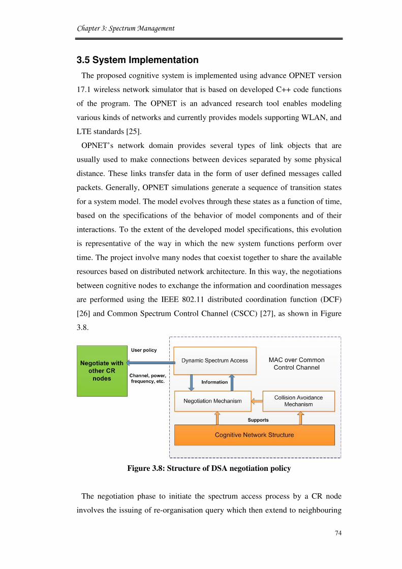
Chapter 3: Spectrum Management
74
3.5 System Implementation
The proposed cognitive system is implemented using advance OPNET version
17.1 wireless network simulator that is based on developed C++ code functions
of the program. The OPNET is an advanced research tool enables modeling
various kinds of networks and currently provides models supporting WLAN, and
LTE standards [25].
OPNET’s network domain provides several types of link objects that are
usually used to make connections between devices separated by some physical
distance. These links transfer data in the form of user defined messages called
packets. Generally, OPNET simulations generate a sequence of transition states
for a system model. The model evolves through these states as a function of time,
based on the specifications of the behavior of model components and of their
interactions. To the extent of the developed model specifications, this evolution
is representative of the way in which the new system functions perform over
time. The project involve many nodes that coexist together to share the available
resources based on distributed network architecture. In this way, the negotiations
between cognitive nodes to exchange the information and coordination messages
are performed using the IEEE 802.11 distributed coordination function (DCF)
[26] and Common Spectrum Control Channel (CSCC) [27], as shown in Figure
3.8.
Figure 3.8: Structure of DSA negotiation policy
The negotiation phase to initiate the spectrum access process by a CR node
involves the issuing of re-organisation query which then extend to neighbouring

Chapter 3: Spectrum Management
75
nodes. The negotiation and building process for the network topology solutions
are explained in [28, 29]. Further details can be found in Appendix A.
In the case of this project, very specific advanced functionality is required and
most of the developing is performed in the PHY and MAC layers. The
challenging task is to integrate the spectrum management model in a new
customised node that is able to increase the performance of the default node in
accessing the spectrum holes. The proposed system, shown in Figure 3.9, is
evaluated using advance OPNET17.1.
Figure 3.9: Cognitive LTE-femtocell systems testbed in OPNET
3.5.1 Integrating the New Cognitive System
This section discusses the integartion of spectrum management modules and
processors to allow the definition of a new set of actions by developing a process
model using the C++ functions in the process domain. The general approach to
develop a process models is shown in Figure 3.10. This is performed by

Chapter 3: Spectrum Management
76
incorporating new process models with the standard OPNET nodes that require
intimate knowledge of the standard, built-in OPNET connections. In new process
models that implement new applications, a quite deep understanding for the
internal functions of the standard process model is required. This knowledge is
needed to determine how to invoke the new process model within the OPNET’s
code.
Figure 3.10: Modified node modules in OPNET
Node models are usually defined via one or more functional elements called
modules and by the data flow between them. The behaviour of individual
modules is specified either via a set of built-in parameters or through one or more
process models. The following work involves the details of the new proposed
modules of management and recourse allocation units. The details of the
particular node and process models are presented in the following subsections.
The 802.11e standard is used with the enables Carrier Sense Multiple Access
with Collision Avoidance (CSMA/CA) based MAC protocol, and has been
considered as a cognitive network in this study [30]. CSMA/CA has the ability to
listen before talk, to implicitly sense PU, and the advantage to effectively solve

Chapter 3: Spectrum Management
77
the cognitive radio self-coexistence issues in the overlapping CR BSSs scenario
is shown in Figure 3.11.
The ‘init’ state obtain the MAC parameter values set by the CR and calculate
the contention periods. Then, ‘idle’ state is the machine enters an idle state and
waits for an incoming event. The event can be either an incoming packet from
the source modules, a feedback interrupt from the MAC process to inform it of a
successful transmission, or ready to send for the next packet to the MAC layer to
contend with other stations for the radio channel. However, the ‘transmit’ state is
able to update the contention window triggers the SEND_PKT event and the state
machine enters the transmit state.
Figure 3.11: Channel access mechanism in MAC (Process Domain)
Algorithm 3.5: CSMA/CA Mechanism
1: // Check if the channel is available.
2: if channel_ available = CR_CSMA_CHANNEL_
AVAILABLE () then;
3: /* transmission attempt failed*/
4: Tx_failure = OPC_FALSE;
5: // If backoff is reached the limited and channel is busy.
6: if (CH_BUSY && BACKOFF_LIMIT_REACHED)
7: end if
All the cognitive base stations are sharing a set of radio channels, and before
any node transmits data, the investigated channel must be idle for a contention

Chapter 3: Spectrum Management
78
period. When detecting certain channel availability, the cognitive radio must be
continuously sense it throughout this period in order to determine whether the
channel is idle or not, this is shown in Algorithm 3.5. However,
ACKnowledgement (ACK) packets enable a cognitive node to determine
whether its transmission was successful or not since it cannot otherwise detect a
collision. The transmitter is completely aware of the collision after it times out
waiting for the corresponding ACK for the packet transmitted. If there is no ACK
packet received or an ACK is received by mistake, the transmitter will try again
to retransmit the data packet until reach the maximum number of retransmissions
that has been allowed before adapting to another channel [31].
3.5.1.1 Generate Management Process Model
The management process model consists of six state conditions: init,
domain_setup, idle, hl_pk_arrival, schedule, and tx_complete, as shown in
Figure 3.12.
Figure 3.12: Management module (Process Domain)
The time interval between each new packet arrival can be modelled as a
constant value or any other value of statistical distribution (normal, Poisson etc.).
The management of the spectrum is activated once a packet arrives at the “init”
state. This will initialise all other process model variables and data structures.

Chapter 3: Spectrum Management
79
Then, the data transmission arrives at the unforced process state model
“domain_setup”. This state is responsible for initialising the reachability set for
this node and updating the position of this node with regards to other project
nodes since the exit the initial state. Next, the “Idle” state checks whether the
incoming packet is a “tx_complete” data packet, higher layer data packet, or a
domain_setup data packet. The actions here as following: if the packet is coming
from higher layer then it goes to “hl_pk_arrival” state, and if the data packet is
coming from “tx_complete”, then it goes to “tx_complete” state. However, if the
packet is coming from “schedule” state then the packet will be queued and then
sent to “hl_pk_arrival” state.
Each incoming higher layer packet is mapped into one of the outgoing
connections to the “schedule” state and the packet. The “schedule” then decides
to transmitte or returne to the “idle” state again depending on the channel
availability and the free buffer size. The state machine “schedule” generates an
interrupt to delay outgoing packet while looking for a transmission opportunity
that suites the transmission frame. This is performed while calculating the current
time slot. If the current time slot is enough to meet the requirements, then, the
transmitter is checked; if the transmitter is free the state machine “schedule” will
deliver the packet to the buffer in “tx_complete” state. At this stage, if there is
enough time to transmit the entire packet, then, the packet is sent down to the
transmitter’s “physical layer” mac_phy_pkt_send () function that sets the
physical characteristics of the transmission channel.
3.5.1.2 Generate Spectrum Resource Allocation
Each new data packet that enters the network specifies the minimum requested
rate which is the minimum amount of bandwidth that the data packets needs to
operate properly, and the maximum requested rate which is the maximum
amount of bandwidth that the data packets can utilise. These values are called the
Requested Bandwidth Range (RBR) and all spectrums’ admitted accesses are
guaranteed to receive the amount of bandwidth within its RBR. If there is a
sufficient amount of bandwidth to support the new data packets request then all
the other data packets that share resources with the newly admitted data packets
are controlled to accommodate the new data packets arrival. As described above
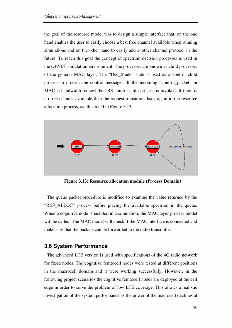
Chapter 3: Spectrum Management
80
the goal of the resource model was to design a simple interface that, on the one
hand enables the user to easily choose a best free channel available when running
simulations and on the other hand to easily add another channel protocol in the
future. To reach this goal the concept of spectrum decision processes is used in
the OPNET simulation environment. The processes are known as child processes
of the general MAC layer. The “Dec_Made” state is used as a control child
process to process the control messages. If the incoming “control_packet” in
MAC is bandwidth request then BS control child process is invoked. If there is
no free channel available then the request transitions back again to the resource
allocation process, as illustrated in Figure 3.13.
Figure 3.13: Resource allocation module (Process Domain)
The queue packet procedure is modified to examine the value returned by the
“RES_ALLOC” process before placing the available spectrum in the queue.
When a cognitive node is enabled in a simulation, the MAC layer process model
will be called. The MAC model will check if the MAC interface is connected and
make sure that the packets can be forwarded to the radio transmitter.
3.6 System Performance
The advanced LTE version is used with specifications of the 4G radio network
for fixed nodes. The cognitive femtocell nodes were tested at different positions
in the macrocell domain and it were working successfully. However, in the
following project scenarios the cognitive femtocell nodes are deployed at the cell
edge in order to solve the problem of low LTE coverage. This allows a realistic
investigation of the system performance as the power of the macrocell declines at

Chapter 3: Spectrum Management
81
the far ends of the cell and femtocells are likely to be used to support
communications at such places. The simulation field is a grid of 1km� with 100
UEs and 50 FBSs. The femtocells are randomly positioned at the edge of the cell
with one LTE-BS was used to simulate the macrocell base station, Mobile Ad-
Hoc Network (MANET) stations as the primary users of the spectrum and
802.11e standard as a cognitive network.
Coverage range is assumed to be 30m for femtocell. LTE base stations have
random trajectories, fixed pedestrian speed of 5km/h and they can have different
types of connections simultaneously active. The simulation considers four types
of traffic connection (HTTP, Data, Video, and VoIP services time interval of
5ms. Results are collected as average values over simulations connection times
of 15 minute each run. The Hata propagation model [32] is used for determining
the level of interference of wireless channel model, and path loss urban medium
city. LTE provides data rates up to 100 Mbits/s in the downlink direction, data
rates up to 50 Mbps in the uplink direction and latencies in the radio access
network of 10 milliseconds.
3.6.1 Results
The performance of the proposed system model of spectrum management is
presented in this section. Four traffic applications (voice, video, data, and HTTP)
are simulated with proposed spectrum management model versus the traditional
cognitive femtocell model in [33]. The studied scenarios are set to use random
spectrum access at variable transmission intervals. A specific numbers of
femtocell nodes are set to coexist with the macrocell base station and other
primary users in an open access model. Therefore, a link is established as long as
the channel condition given by the RBR is acceptable within the transmission
distance. The monitoring indicators were developed to show the new system
solution performance of each type of traffic individually to allow better
performance evaluation of the studied solution. Assuming all users are moving
with pedestrian speed, then mobility has very small impact on the evaluations
and results are subject to change only because of the spectrum allocation
function. Table 3.1 presents the system parameters for the simulation. All users
are assumed to be independent from each other, and the mobility of individual

Chapter 3: Spectrum Management
82
users is not considered in this scenario.
Table 3.1: New LTE-femtocell system characteristics
Name Value
Macrocell radius 1000 m
Femtocell radius 30 m
Bandwidth 5 MHz
Femtocell power 20 dBm
LTE transmit power 40 dBm
Noise variance at receiver -95.0
Path loss exponent 3
Packet size 1024 bits
Number of traffic per user 4
The results show that, as the connections time decreases due to the increase in
the site femtocell users, the Bit Error Rates (BERs) of various applications
increases slightly since fewer radio spectrum resources are available for the
FUEs to transmit, as shown in Figure 3.14. The femtocell proposed system with
an increasing numbers of end-users performs better than the traditional femtocell
node case in each simulated traffic case. Although the BER values fluctuate for
various traffic models, it can be noticed that the similar traffic profile runs
reflects a significant difference in results. For example, the proposed spectrum
management model has a very low BER with voice traffic compared to the very
high values of BER for the same traffic but with the traditional scheme of
scheduling and accessing the available transmission opportunities. This show the
advantages gained from the new spectrum allocation scheme and the successful
installation for assigning the requested bandwidth to the admitted users.
The impact of increasing the number of femtocell users on the SNR
performance is considered, as shown in Figure 3.15. The proposed system selects
a channel at each time slot for certain traffic type and moves to the next traffic in
priority of sending and queue. The average transmission rate is a function for the
time available at instance. Notice that deploying the proposed femtocell network
due to the heavy penetration loss of the signal from macrocell BSs, the femtocell
network is observed to boost up the SINR of the whole network with maximum
50dbm. However, significant reduction in the service time can be achieved in the
low load region if randomise the selection of free channels available.

Chapter 3: Spectrum Management
83
Figure 3.14: BER vs. number of site femtocell users
Figure 3.15: SNR vs number of site femtocell users
10 20 30 40 50 60 70 80 90 1000.115
0.12
0.125
0.13
0.135
0.14
0.145
0.15
BE
R
Number of Cognitive Femtocell Users
Proposed scheme- VoiceProposed scheme- Voice
Traditional scheme-VoiceTraditional scheme-Voice
Proposed scheme-DataProposed scheme-Data
Traditional scheme-DataTraditional scheme-Data
Proposed scheme-VideoProposed scheme-Video
Traditional scheme-VideoTraditional scheme-Video
Proposed scheme-HTTPProposed scheme-HTTP
Traditional scheme-HTTPTraditional scheme-HTTP
0 10 20 30 40 50 60 70 80 90 10030
35
40
45
50
SN
R
Number of Femtocell Users
Proposed scheme- VoiceProposed scheme- Voice
Traditional scheme-VoiceTraditional scheme-Voice
Proposed scheme-DataProposed scheme-Data
Traditional scheme-DataTraditional scheme-Data
Proposed scheme-VideoProposed scheme-Video
Traditional scheme-VideoTraditional scheme-Video
Proposed scheme-HTTPProposed scheme-HTTP
Traditional scheme-HTTPTraditional scheme-HTTP

Chapter 3: Spectrum Management
84
The results show that the proposed system increases the performance of
femtocells system in accessing the available spectrum band. This is shown
through reducing the total transmitted power during link establishment and
connection compared to the traditional scheme as a function for the number of
femtocell users, as shown in Figure 3.16.
The high transmitted power is a result of inefficient allocation that leads to
huge number of links terminations and links re-establishments while connecting
to end-users. This has been solved in the proposed spectrum allocation scheme
that helps to maintain links for longer times and enables to reduce the numbers of
links terminations and hence the power required for multi-transmissions. The
proposed cognitive system is capable of reduced the transmitted power from 5W
to 4W when the number of end users is 10. This means the new system is able to
reduce the transmitted power by 20% as a way to achieve spectrum utilisation.
Figure 3.16: Power vs number of site femtocell users
The increase in throughput is more gradual and noticeable with the increase in
numbers of femtocell users, as shown in Figure 3.17, since the proposed system
is able to nearly utilise all the available bandwidth. The given results are a
function of a particular traffic pattern that is used in the simulation settings. For
0 10 20 30 40 50 60 70 80 90 1000
1
2
3
4
5
6
7
8
9
10
Tra
nsm
itte
d P
ow
er
(W)
Number of Cognitive Femtocell Users
Proposed scheme- VoiceProposed scheme- Voice
Traditional scheme-VoiceTraditional scheme-Voice
Proposed scheme-DataProposed scheme-DataTraditional scheme-DataTraditional scheme-Data
Proposed scheme-VideoProposed scheme-VideoTraditional scheme-VideoTraditional scheme-Video
Proposed scheme-HTTPProposed scheme-HTTPTraditional scheme-HTTPTraditional scheme-HTTP

Chapter 3: Spectrum Management
85
example, in the voice case, the network throughput steadily increases with an
increase in the number of users. However, the total throughput in this case is
greater with the proposed system compared with the than normal channel
allocation model. There is degradation among all patterns as there is always a
chunk of bandwidth that the femtocell is unable to use and access. In the case of
a cognitive network, the total system throughput can be improved further by
assigning certain femtocells to secure channels and predefined services. This
enables the scheduling of non-consecutive nodes in the chain to use non-
overlapping parts of the spectrum.
Figure 3.17 Throughput vs number of site femtocell users
Figure 3.18 shows the end-to-end time delays for different types of traffic. The
time delay increases as the numbers of end-users increases. However, the
improvement of adding the proposed model is quite clear in all different traffic
profiles. Furthermore, the system delay for all traffics types is mostly the same
when the numbers of users dropped to below 10. When each flow generates
traffic in connection with the increase in number of users’, the proposed system
adaptively allocates more bandwidth to each traffic flow, and hence traffic
patterns with larger white space achieve higher throughput and lower time delay
0 10 20 30 40 50 60 70 80 90 1000
50
100
150
200
250
Th
rou
gh
pu
t (p
kts
/sec)
Number of Cognitive Femtocell Users
Proposed scheme- VoiceProposed scheme- Voice
Traditional scheme-VoiceTraditional scheme-Voice
Proposed scheme-DataProposed scheme-Data
Traditional scheme-DataTraditional scheme-Data
Proposed scheme-VideoProposed scheme-Video
Traditional scheme-VideoTraditional scheme-Video
Proposed scheme-HTTPProposed scheme-HTTP
Traditional scheme-HTTPTraditional scheme-HTTP

Chapter 3: Spectrum Management
86
compared to non- the proposed models. In the proposed scheme, more UEs
achieve search procedure of available channels, and it accesses the free spectrum
very quickly.
Figure 3.18: End-to-end time delay vs number of site femtocell users
3.7 Spectrum Utilisation based Bandwidth Allocation
3.7.1 Channel Allocation in LTE and Femtocell
Different channel allocation approaches can be considered for LTE-femtocell
deployments to ensure flexibility and optimisation in terms of spectrum access
options. The key decision depends on several factors such as how many carriers
are available for cognitive users, efficient spectrum utilisation, and whether
public access is granted or a private access model is preferred. In this section, a
range of practical spectrum allocation schemes and the criteria is investigated in
order to choose between them, as shown schematically in Figure 3.19.
0 10 20 30 40 50 60 70 80 90 1002
2.5
3
3.5
4
4.5
5
5.5
6
6.5
7
En
d-t
o-E
nd
Tim
e D
ela
y (
msec)
Proposed scheme- VoiceProposed scheme- Voice
Traditional scheme-Voice Traditional scheme-Voice
Proposed scheme-VideoProposed scheme-Video
Traditional scheme-VideoTraditional scheme-Video
Proposed scheme-DataProposed scheme-Data
Traditional scheme-DataTraditional scheme-Data
Proposed scheme-HTTPProposed scheme-HTTP
Traditional scheme-HTTPTraditional scheme-HTTP
Number of Cognitive Femtocell Users
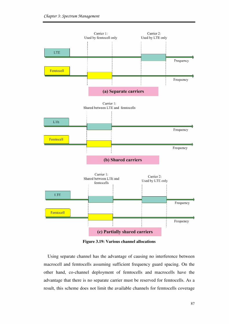
Chapter 3: Spectrum Management
87
Figure 3.19: Various channel allocations
Using separate channel has the advantage of causing no interference between
macrocell and femtocells assuming sufficient frequency guard spacing. On the
other hand, co-channel deployment of femtocells and macrocells have the
advantage that there is no separate carrier must be reserved for femtocells. As a
result, this scheme does not limit the available channels for femtocells coverage

Chapter 3: Spectrum Management
88
and can be used in coexistence with macrocells. In the case of partially shared
channels, some carriers with long times of availability can be shared between
macrocell and femtocell base stations. While the co-channel operation mode can
occur in combination with shared channel allocation at later times. The LTE base
stations has the priority of accessing all the available channels whilst femtocells
can only use sections of the available channels when they are not used by the
macrocell. When a macrocell user comes close to an FBS that has no access to
the spectrum, it keeps its connection with the macrocell LTE band without
interfering with the femtocell transmission domain users [34].
3.7.2 Queuing Mechanism
Each router must implement some queuing discipline that governs how packets
are buffered while waiting to be transmitted. Various queuing disciplines can be
used to control which packets get transmitted (bandwidth allocation) and which
packets get dropped (buffer space). The queuing discipline also affects the
latency experienced by a packet, by determining how long a packet may wait to
be transmitted. Examples of the common queuing disciplines are First-In First-
Out (FIFO) queuing and Priority Queuing (PQ). The PQ is a simple variation of
the basic FIFO queuing. The idea is to mark each packet with a priority; the mark
could be set, for example, in the IP Type of Service (ToS) field [35].
In PQ, packets that arrive at the output link are classified into more than one
queue based on their priorities. The packets with highest priority are then served
first, next the second higher priority and so on. In order to assign priority the
packet header (for example, the value of the ToS bits in an IPv6 packet, its
source or destination IP address, its destination port number, or other criteria
should be used. Each priority class typically has its own queue for choosing a
packet to transmit. The priority queuing discipline will start by transmitting the
packets of highest priority class from the nonempty queue (that has packets
awaiting transmission). The choice among packets in the same priority class is
typically achieved in a FIFO manner. The problem with PQ is that lower-priority
packets may get little attention [36]. A queue scheduling discipline manages the
allocation of network resources among different traffic flows by selecting the
next packet for processing.

Chapter 3: Spectrum Management
89
3.8 System Model based Priority Spectrum Allocation
The LTE macrocell and cognitive femtocell base station are considered using
several queuing applications. Assuming that FUEs produce ��� applications
represented of an order 1, 2, · · · , �, and the users are moving in the same
transmission domain of the base station. Then, each request received at the base
station is assigned a priority value according to the system delay requirements of
different users. Simultaneously, the cognitive base station explores the
transmission blocks in � sub-bands of an available spectrum. Each sub-band is
represented by��� = 1, 2, · · · ,�. An OFDM symbol consists of � narrow band
sub carriers divided over a fixed bandwidth��.
Based on the size of the detected block in a sub-band, the base station computes
the number of active sub-carriers (A !)in sub-band"��, where ! represents
the number of occupied or inactive sub-carriers in an OFDM symbol of total A
subcarriers. This process is repeated over all sub-bands 1, 2, · · · , � in the
targeted spectrum of operation, as shown in Figure 3.20 [37].
Figure 3.20: OFDM, a) Multicarrier transmission, b) orthogonally [37]
The proposed priority allocation scheme is specifically designed for OFDM
based wireless systems that can support dynamic spectrum access. This
bandwidth can span across a definite number of sub-bands in the spectrum
considered. Hence, it is essential to have knowledge of the following:

Chapter 3: Spectrum Management
90
• LTE user occupancy in the sub-bands to compute idle periods.
• Bandwidth occupied by each LTE user in these sub-bands to compute
the numbers of inactive OFDM sub-carriers left to femtocells usage.
Once this information is available, the cognitive base station can decide on the
number of sub-carriers to be made inactive.
Higher spectral efficiency can be achieved by increasing parallel transmissions
in less number of time slots per frame. This can be defined also as scheduling the
maximum number of parallel transmissions with the minimum number of time
slots. Suppose that an �#$-cognitive users occupies a bandwidth of ��% in sub-
band��� = 0, 1,···,�. The number of OFDM sub-carriers in sub-band ��� is
+�,+� -.
[38]. Thus, the number of inactive sub-carriers �/ can be expressed as:
�/ =0��1 2 -��3�
%45(3.1)
If we assume that all the LTEs occupy the same bandwidth ��89:;< in their
respective sub-bands, then Equation .3.1 can be re-written as:
�/ = (�-)2��89:;<�� 3(3.2)
As a result, the femtocell cognitive node can compute the effective capacity
=8>> as:
=8>> = 21 ���89:;<�� 3 =(3.3)
where = denotes the individual sub-band capacity.
3.8.1 Spectrum Allocation Technique
In this scheme, the cognitive base station constructs a priority queue for real
time applications and it allocates the most important application to the available
sub-band that satisfies the joint requirements of delay and BER. This strategy
follows the spectrum pooling technique illustrated in [37].
This technique is dealing with spectrum as one pool, so the CR will be able to
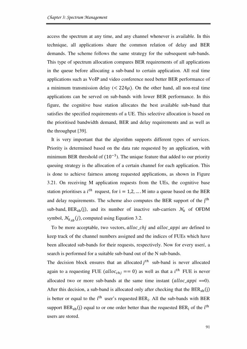
Chapter 3: Spectrum Management
91
access the spectrum at any time, and any channel whenever is available. In this
technique, all applications share the common relation of delay and BER
demands. The scheme follows the same strategy for the subsequent sub-bands.
This type of spectrum allocation compares BER requirements of all applications
in the queue before allocating a sub-band to certain application. All real time
applications such as VoIP and video conference need better BER performance of
a minimum transmission delay (< 224@). On the other hand, all non-real time
applications can be served on sub-bands with lower BER performance. In this
figure, the cognitive base station allocates the best available sub-band that
satisfies the specified requirements of a UE. This selective allocation is based on
the prioritised bandwidth demand, BER and delay requirements and as well as
the throughput [39].
It is very important that the algorithm supports different types of services.
Priority is determined based on the data rate requested by an application, with
minimum BER threshold of(10AB). The unique feature that added to our priority
queuing strategy is the allocation of a certain channel for each application. This
is done to achieve fairness among requested applications, as shown in Figure
3.21. On receiving M application requests from the UEs, the cognitive base
station prioritises a �#$ request, for i = 1,2, … .M into a queue based on the BER
and delay requirements. The scheme also computes the BER support of the jGH sub-band,BERLM(j), and its number of inactive sub-carriers �/ of OFDM
symbol, �/��(N),computed using Equation 3.2.
To be more acceptable, two vectors,�OOPQ_QℎN and �OOPQ_�RR� are defined to
keep track of the channel numbers assigned and the indices of FUEs which have
been allocated sub-bands for their requests, respectively. Now for every user�, a
search is performed for a suitable sub-band out of the N sub-bands.
The decision block ensures that an allocatedN#$ sub-band is never allocated
again to a requesting FUE (�OOPQS$T == 0) as well as that a �#$ FUE is never
allocated two or more sub-bands at the same time instant (�OOPQ_�RR� ==0).
After this decision, a sub-band is allocated only after checking that the BERLM(j) is better or equal to the iGH user’s requestedBER1. All the sub-bands with BER
support BERLM(j) equal to or one order better than the requested BER1 of the iGH users are stored.
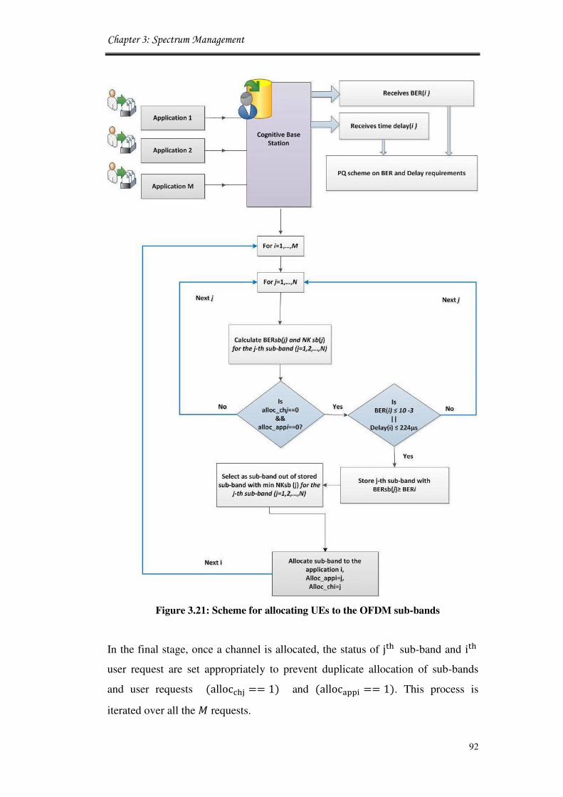
Chapter 3: Spectrum Management
92
Figure 3.21: Scheme for allocating UEs to the OFDM sub-bands
In the final stage, once a channel is allocated, the status of jGH sub-band and iGH user request are set appropriately to prevent duplicate allocation of sub-bands
and user requests (allocYHZ == 1) and (alloc[\\1 == 1). This process is
iterated over all the � requests.
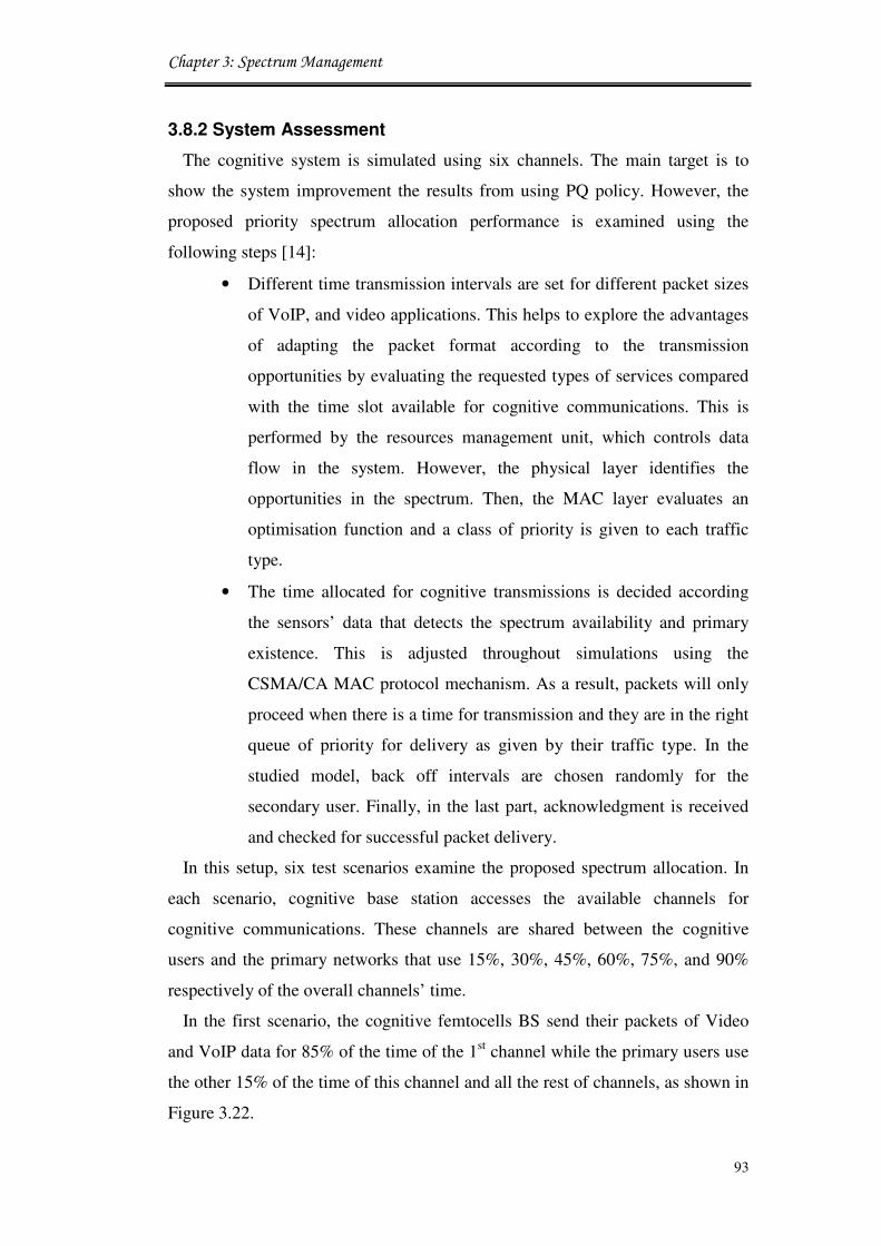
Chapter 3: Spectrum Management
93
3.8.2 System Assessment
The cognitive system is simulated using six channels. The main target is to
show the system improvement the results from using PQ policy. However, the
proposed priority spectrum allocation performance is examined using the
following steps [14]:
• Different time transmission intervals are set for different packet sizes
of VoIP, and video applications. This helps to explore the advantages
of adapting the packet format according to the transmission
opportunities by evaluating the requested types of services compared
with the time slot available for cognitive communications. This is
performed by the resources management unit, which controls data
flow in the system. However, the physical layer identifies the
opportunities in the spectrum. Then, the MAC layer evaluates an
optimisation function and a class of priority is given to each traffic
type.
• The time allocated for cognitive transmissions is decided according
the sensors’ data that detects the spectrum availability and primary
existence. This is adjusted throughout simulations using the
CSMA/CA MAC protocol mechanism. As a result, packets will only
proceed when there is a time for transmission and they are in the right
queue of priority for delivery as given by their traffic type. In the
studied model, back off intervals are chosen randomly for the
secondary user. Finally, in the last part, acknowledgment is received
and checked for successful packet delivery.
In this setup, six test scenarios examine the proposed spectrum allocation. In
each scenario, cognitive base station accesses the available channels for
cognitive communications. These channels are shared between the cognitive
users and the primary networks that use 15%, 30%, 45%, 60%, 75%, and 90%
respectively of the overall channels’ time.
In the first scenario, the cognitive femtocells BS send their packets of Video
and VoIP data for 85% of the time of the 1st channel while the primary users use
the other 15% of the time of this channel and all the rest of channels, as shown in
Figure 3.22.

Chapter 3: Spectrum Management
94
In the second scenario, cognitive femtocells are using channel one for 85% of
its time and channel two for 70% of its time, while primary users use all the rest
of the time and channels for primary broadcasting. The same sequence is
applicable for the rest of the channels (up to six channels) that are assumed to be
allocated for cognitive systems. To compare the performance of the proposed
system with and without PQ, the above evaluations are performed in which the
traditional PQ applied at the femtocell node.
Figure 3.22: Channels free time as a percentage
3.9 System performance
3.9.1 System Specification
The proposed cognitive networks are simulated for the LTE-femtocell nodes
using the spectrum utilisation based priority queuing strategies. The simulation
environment, considers 6 different scenarios. Each scenario has three cognitive
femtocell nodes. Each FBS have two users transmitting VoIP and Video
applications. Moreover, the main macrocell base station is created using the LTE

Chapter 3: Spectrum Management
95
standards. The Ad hoc On-Demand Distance Vector (AODV) routing protocol
intended for use by mobile nodes. It offers quick adaptation to dynamic link
conditions while the main base station is linked to the femtocell nodes via optical
fibre connections. In this configuration, a profile for each client was set that uses
two applications as mentioned above.
For setting the free time profile, different time intervals within LTE are
considered as multiples of a basic time unit]: = 1/30720000. The system
frame has a length of 10`� for 20 slots, ]>a;b8 = 307200 ∗ ]:. Each frame
is divided into ten equally sized sub-frames of ]�:�_>a;b8 = 1`� in length
(]�:�_>a;b8 = 30720 ∗ ]:). Scheduling is done on a subframe basis for both
the downlink and uplink. Each sub-frame consists of two equally sized slots of
0.5`� in length ]�<e# = (15360 ∗]:). The time of the simulation run was set to 600 sec. The same network is used in
each of the studied scenarios with the same profile of free channel time and
strategies of each of the two different cases. The main goals of the application to
achieve spectrum utilisation based priority queuing in the cognitive network in
order to overcome the congestion and time delays during packet delivery for
cognitive applications. The network features were set as specified in Table 3.2.
Table 3.2: Spectrum allocation system parameters
Parameter Value
Type of traffic heavy traffic load
Video coding MPEG4
Type of video service streaming multimedia
VoIP PCM quality speech
Type of voice service Interactive voice
Packet size 1500 bytes
Frame Duration 5ms
Slot time 10µs
Buffer size 500kbps
packet length 1024 byte
LTE Power 40dBm
Noise figure 9 dB
Antenna gain 15dBi
PHY technique OFDM
Femtocell Power 20dBm
Bandwidth 5MHz
Noise figure 9 dB
Antenna gain 5dBi

Chapter 3: Spectrum Management
96
3.9.2 Results and Analysis
The performance of the cognitive system is examined using two approaches:
Firstly, with new proposed priority spectrum allocation policy. Secondly, using
the traditional LTE-femtocell architecture and without the priority queuing PQ
policy installation.
Figure 3.23 shows the throughput comparison for the two cases of PQ scheme
and traditional scheme with video and VoIP traffic applications. By using
priority spectrum allocation, throughput is improved by approximately 10%. The
results suggest an increase in the overall network throughput. In other words,
when voice data becomes part of a network, the priority has to be given to real
time applications, while the video packets are buffered. The increase in the
number of channels available for the cognitive communication leads to a
considerable increase in the throughput. The analysis of this work was defined
for a certain profile of channel’s free time and availability. This means that the
throughput can be increased or decreased as a function of the increase or
decrease in the availability of resources. This is highly affected by the activities
of the PU and the number of packets to be delivered by the cognitive network.
Figure 3.24 shows the end-to-end time delay for the two different cases. The
simulation results will also show the effect of the slot size on queuing delay and
the end to end MAC delay. The VoIP shows the lowest average delay, in
contrast, to Video, which has the highest medium access delay. In both cases, the
installation of the PQ shows a significant improvement in the system
performance compared to the traditional spectrum allocation scheme. These
results show that scheduling spectrum access as a function for the client’s
priority can improve the overall cognitive network performance.
Figure 3.25 shows the medium access delays for the simulated scenarios.
Considering this graph, it is obvious that all QoS requirements of the priority
policy are met using the proposed scheme. This medium access delay is
calculated as the duration from the time when it is inserted into the transmission
queue, (which is the arrival time of the higher layer data packet and the creation
time for all other frames types), until the time when the frame is sent to the
physical layer for the first time.
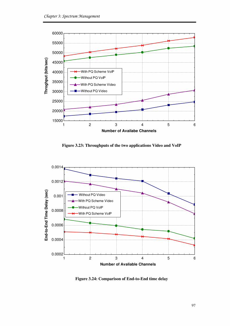
Chapter 3: Spectrum Management
97
Figure 3.23: Throughputs of the two applications Video and VoIP
Figure 3.24: Comparison of End-to-End time delay
1 2 3 4 5 615000
20000
25000
30000
35000
40000
45000
50000
55000
60000
Number of Availabe Channels
Th
rog
hp
ut
(bit
s/s
ec
)
Without PQ VoIP
With PQ Scheme VoIPWith PQ Scheme VoIP
With PQ Scheme VideoWith PQ Scheme Video
Without PQ VideoWithout PQ Video
1 2 3 4 5 60.0002
0.0004
0.0006
0.0008
0.001
0.0012
0.0014
Number of Avaliable Channels
En
d-t
o-E
nd
Tim
e D
ela
y (
sec)
Without PQ Video Without PQ Video
With PQ Scheme VideoWith PQ Scheme Video
Without PQ VoIPWithout PQ VoIP
With PQ Scheme VoIPWith PQ Scheme VoIP

Chapter 3: Spectrum Management
98
Figure 3.25: Medium access delay for the two applications Video and VoIP
Figure 3.26: Traffic sent and received for Video
1 2 3 4 5 60.0002
0.0004
0.0006
0.0008
0.001
0.0012
0.0014
Med
ium
Acc
ess D
ela
y (
sec
)
Without PQ VideoWithout PQ Video
With PQ Scheme VideoWith PQ Scheme Video
Without PQ VoIPWithout PQ VoIP
With PQ Scheme VoIPWith PQ Scheme VoIP
Number of Availabe Channels
1 2 3 4 5 61000
1500
2000
2500
3000
3500
4000With PQ Scheme Video sent
Number of Availabe Channels
Vid
eo
Tra
ffic
(b
its
/sec
)
Without PQ Video sentWithout PQ Video sent
With PQ Scheme Video receivedWith PQ Scheme Video received
Without PQ Video receivedWithout PQ Video received
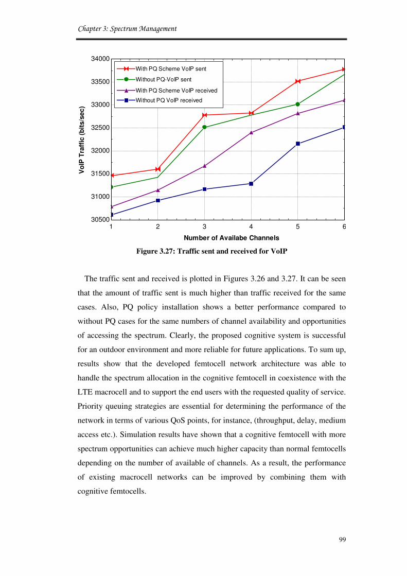
Chapter 3: Spectrum Management
99
Figure 3.27: Traffic sent and received for VoIP
The traffic sent and received is plotted in Figures 3.26 and 3.27. It can be seen
that the amount of traffic sent is much higher than traffic received for the same
cases. Also, PQ policy installation shows a better performance compared to
without PQ cases for the same numbers of channel availability and opportunities
of accessing the spectrum. Clearly, the proposed cognitive system is successful
for an outdoor environment and more reliable for future applications. To sum up,
results show that the developed femtocell network architecture was able to
handle the spectrum allocation in the cognitive femtocell in coexistence with the
LTE macrocell and to support the end users with the requested quality of service.
Priority queuing strategies are essential for determining the performance of the
network in terms of various QoS points, for instance, (throughput, delay, medium
access etc.). Simulation results have shown that a cognitive femtocell with more
spectrum opportunities can achieve much higher capacity than normal femtocells
depending on the number of available of channels. As a result, the performance
of existing macrocell networks can be improved by combining them with
cognitive femtocells.
1 2 3 4 5 630500
31000
31500
32000
32500
33000
33500
34000
Number of Availabe Channels
Vo
IP T
raff
ic (
bit
s/s
ec)
With PQ Scheme VoIP sent
Without PQ-VoIP sentWithout PQ-VoIP sent
With PQ Scheme VoIP receivedWith PQ Scheme VoIP received
Without PQ VoIP receivedWithout PQ VoIP received

Chapter 3: Spectrum Management
100
3.10 Conclusion
This chapter presented two spectrum allocation approaches. Firstly, novel
resource management model is proposed to improve the bandwidth allocation in
dynamic spectrum access models. This is performed by processing transmission
requests in terms of traffic frames, then scheduling the traffic according to the
available bandwidth in order to increase the capacity of delivered services. The
proposed spectrum management framework incorporates PHY and MAC layers
in order to assign suitable services to the available transmission opportunities.
The proposed spectrum management system with the provided algorithms allows
increasing the utilisation of the available resources for the LTE-femtocell system
and improves the overall spectrum efficiency.
Secondly, a new spectrum allocation technique is proposed to perform a priority
queuing for real time applications and allocates the most important application to
the available sub-band to satisfy the joint requirements of delay and BER. This
approach is introduced to identify the QoS requirements and white space
available for transmissions. Real time applications are assigned to different data
queues and transmission decision choice between them is made whenever the
investigated channel matches the QoS requested and can maintain high
throughput linking to end-users in order to achieve spectrum utilisation.
The proposed system models achieved higher degrees of spectrum efficiency
in terms of lower end-to-end time delays, lower medium occupancy, high
spectral efficiency, and considerably higher throughput. New research topics that
re-design systems from cognitive users’ viewpoints are raised to the industrial
and research communities.
3.11 References
[1] S. Al-Rubaye, A. A-Dulaimi, L. AL-Saeed, H. Al-Raweshidy, E. Kadhum,
and W. Ismail, “Development of Heterogeneous Cognitive Radio and
Wireless Access Network,” In Proc. of the 24 meeting of the Wireless
World Research Forum (WWRF), Penang, Malaysia, April 2010.
[2] L. Berlemann, G. Dimitrakopoulos, K. Moessner, and J. Hoffmeyer,
“Cognitive Radio and Management of Spectrum and Radio Resources in
Reconfigurable Networks,” White Paper, Wireless World Research Forum

Chapter 3: Spectrum Management
101
(WWRF), Paris, France, December 2005.
[3] G. Dimitrakopoulos, P. Demestichas, D. Grandblaise, K. Mößner, J.
Hoffmeyer, and J. Luo, “Cognitive Radio, Spectrum and Radio Resource
Management,” White Paper, Wireless World Research Forum Working
Group 6, Toronto, Canada, November 2004.
[4] M. Wadhwa, C. Xin, M. Song, and E. K. Park, “Throughput Analysis for a
Contention-Based Dynamic Spectrum Sharing Model,” IEEE Transactions
on Wireless Communications, vol. 9, no. 4, pp. 1426 - 1432, April 2010.
[5] J. Xiang, Y. Zhang, T. Skeie, and L. Xie, “Downlink Spectrum Sharing for
Cognitive Radio Femtocell Networks,” IEEE Systems Journal, vol. 4, no.
4, pp. 524 - 534, 2010.
[6] J. Jin, and B. Li, “Cooperative Resource Management in Cognitive WiMAX
with Femto Cells,” In Proc. of the 29th
Annual IEEE International
Conference on Computer Communications (IEEE INFOCOM), San Diego,
USA, March 2010, pp. 1 - 9.
[7] S. Lien, C. Tseng, K. Chen, and C. Su, “Cognitive Radio Resource
Management for QoS Guarantees in Autonomous Femtocell Networks,” In
Proc. of the International Conference on Communications (ICC 2010),
Cape Town, South Africa, May 2010, pp. 1 - 6.
[8] J. Xie, I. Howitt, and A. Raja, “Cognitive Radio Resource Management
Using Multi-Agent Systems,” In Proc. of the IEEE Consumer
Communications and Networking Conference (CCNC), Nevada, January
2007, pp. 1123 - 1127.
[9] L. Chen, S. Low, J. Doyle, and M. Chiang, “Cross-layer congestion control
routing and scheduling design in ad hoc wireless networks,” In Proc. of the
25th IEEE International Conference on Computer Communications,
Barcelona, Spain, April 2006, pp. 1 - 13.
[10] S. Ramanathan and E. Lloyd, “Scheduling algorithms for multi-hop radio
networks”, IEEE Journal ACM Transaction on Network, vol. 1, no. 1, pp.
166 - 177, 1993.
[11] Y. Zhang, and C. Leung, “Cross-Layer Resource Allocation for Mixed
Services in Multiuser OFDM-Based Cognitive Radio Systems”, IEEE

Chapter 3: Spectrum Management
102
Transactions on Vehicular Technology, vol. 58, no. 8, pp. 4605 - 4619,
2009.
[12] R. Wang, V. K. Lau, L. Lv, and B. Chen, “Joint Cross-Layer Scheduling
and Spectrum Sensing for OFDMA Cognitive Radio Systems,” IEEE
Transactions on Wireless Communications, vol. 8, no. 5, pp. 2410 - 2416,
2009.
[13] H. Jung, “Cross-Layer Management with Interference-Aware Resource
Allocation in OFDMA Femtocell Networks,” PhD thesis, Department of
Electrical and Electronic Engineering, Yonsei University, South Korea,
2010.
[14] S. Al-Rubaye, A. Al-Dulaimi and J. Cosmas, “Cognitive Femtocells: Future
Wireless Networks for Indoor Applications,” IEEE Vehicular Technology
Magazine, vol. 6, no. 1, pp. 44 - 51, 2011.
[15] N. Saquib, E. Hossain, L. B. Le, and D. I. Kim, “Interference Management
in OFDMA Femtocell Networks: Issues and Approaches,” IEEE Wireless
Communication, vol. 19, no. 12, pp. 86 - 95, 2012.
[16] IEEE Standard for Information Technology-Telecommunications and
Information Exchange between Systems-Local and Metropolitan Area
Networks-Specific Requirements, “Part 11: Wireless LAN Medium Access
Control (MAC) and Physical Layer (PHY) Specifications,” IEEE STD
802.11-2007 (Revision of IEEE STD 802.11-1999), pp. 1 - 1076, March
2007.
[17] B. Vucetic, “An adaptive coding scheme for time-varying channels,” IEEE
Transection on Wireless Communication, vol. 39, pp. 653 - 663, May
1991.
[18] I. Akyildiz, B. Lo, and R. Balakrishnan, “Cooperative spectrum sensing in
cognitive radio networks: A survey,” Journal of Elsevier Physical
Communication, vol. 4, no. 2011, pp. 40 - 62, March 2011.
[19] W. Lee and I. Akyildiz, “Optimal Spectrum Sensing Framework for
Cognitive Radio Networks,” IEEE Transactions on Wireless
Communications, vol. 7, no. 10, pp. 3845 - 3857, October 2008.

Chapter 3: Spectrum Management
103
[20] R. Kaniezhil, C. Chandrasekar, and S. Nithya Rekha, “Channel selection
for Selective Sensing using Cognitive Radio Nodes International,” Journal
of Computer Applications, vol. 39, no. 3, pp. 20 - 25, 2012.
[21] W. Lee, and I. Akyildiz, “A Spectrum Decision Framework for Cognitive
Radio Networks,” IEEE Transactions on Mobile Computing, vol. 10, no. 2,
pp. 161 - 174, 2011.
[22] I. Akyildiz, W. Lee, M. Vuran, and S. Mohanty, “Next Generation/
Dynamic Spectrum Access/Cognitive Radio Wireless Networks: a
Survey,” Computer Networks, Elsevier, vol. 50, no. 13, pp. 2127 - 2159,
2006.
[23] R. Racu, L. Li, R. Henia, A. Hamann, and R. Ernst, “Improved Response
Time Analysis of Tasks Scheduled under Preemptive Round-Robin,” In
Proc. of the 5th
IEEE Hardware/Software Code sign and System Synthesis,
Salzburg, Austria, 2007 , pp. 179 - 184.
[24] Y. Lai and Y. Chen, “Designing and Implementing an IEEE 802.16
Network Simulator for Performance Evaluation of Bandwidth Allocation
Algorithms,” In Proc. of the 11th
IEEE International Conference on High
Performance Computing and Communications, Seoul, Korea, June 2009,
pp. 432 - 437.
[25] OPNET Modeller, www.opnet.com, accessed on December 2011.
[26] IEEE Standard 802.11-1999, “Wireless LAN Medium Access Control
(MAC) and Physical Layer (PHY) Specifications,” November 1999.
[27] B. F. Lo, “A survey of common control channel design in cognitive radio
networks,” Journal of Physical Communication, Elsevier, vol. 4, no. 1, pp.
26 - 39, January 2011.
[28] R. W. Thomas, D. H. Friend, L. A. DaSilva, and A. B. MacKenzie,
“Cognitive Networks: Adaptation and Learning to Achieve End-to-End
Performance Objectives,” IEEE Communications Magazine, vol. 44, no.
12, pp. 51 - 57, December 2006.
[29] H. Su and X. Zhang, “Cross-Layer Based Opportunistic MAC Protocols for
QoS Provisionings over Cognitive Radio Wireless Networks,” IEEE
Journal on Selected Areas in Communications, vol. 26, no. 1, January
2008.

Chapter 3: Spectrum Management
104
[30] Q. Zhang, F. Fitzek, and V. Iversen, “Cognitive Radio MAC Protocol for
WLAN,” In Proc. of the in IEEE International Symposium on Personal,
Indoor and Mobile Radio Communications (PIMRC), Cannes, France,
2008, pp. 1 - 6.
[31] R. Bruno, M. Conti, and E. Gregori, “Optimization of Efficiency and
Energy Consumption in p-Persistent CSMA-Based Wireless LANs,” IEEE
Transections on Mobile Computing, vol. 1, no. 1, pp. 10 - 31, March 2002.
[32] D. Har, A. Watson, and A. Chadney, “Comment on diffraction loss of
rooftop-to-street in COST 231-Walfisch-Ikegami model,” IEEE
Transactions on Vehicular Technology, vol. 48, no. 5, pp. 1451 - 1452,
September 1999.
[33] J. M. Torregoza, R. Enkhbat, and W. Hwang, “Joint Power Control, Base
Station Assignment, and Channel Assignment in Cognitive Femtocell
Networks,” EURASIP Journal on Wireless Communications and
Networking, vol. 2010, 14 pages, 2010.
[34] J. Hobby and H. Claussen, “Deployment Options for Femtocells and Their
Impact on Existing Macrocellular Networks,” Bell Labs Technical Journal,
vol.13, no. 4, pp. 145 - 160, February 2009.
[35] T. Velmurugan , H. Chandra , and S. Balaji , “Comparison of Queuing
Disciplines for Differentiated Services using OPNET,” In Proc. of the
International Conference on Advances in Recent Technologies in
Communicatilon and Computing, India, 2009.
[36] H. M. Asif and E. M. El-Alfy, “Performance Evaluation of Queuing
Disciplines for Multi-Class Traffic Using OPNET Simulator,” In proc. of
the IEEE 7th
International Conference on Mathematical Methods and
Computational Techniques in Electrical Engineering, Sofia, pp. 1 - 6,
2005.
[37] T. A. Weiss and F. K. Jondral, “Spectrum pooling: an innovative strategy
for the enhancement of spectrum efficiency,” IEEE Communications
Magazine, vol. 42, no. 3, pp. 8 - 14, 2004.
[38] B. Jung, J. Kwon, H. Jin, and D. Sung, “Sub-band Spreading Technique for
Adaptive Modulation in OFDM Systems,” Journal of Communications and
Networks, vol. 10, no. 1, pp. 71 - 78, 2008.

Chapter 3: Spectrum Management
105
[39] R. Rajbanshi, A. M. Wyglinski, and G. J. Minden, “An efficient
implementation of NC-OFDM transceivers for cognitive radios,” In Proc.
of the IEEE 1st International Conference on Cognitive Radio Oriented
Wireless Networks and Communications (Crowncom), Mykonos Island,
Greece, 2006.

Chapter 4 - Power Management and Coverage Planning
106
Chapter 4Chapter 4Chapter 4Chapter 4
Radio Power Management and
LTE Coverage Planning
Power management is an important factor for mobile networks that employ
multi-tier levels and a diverse set of transmission operations. Since a new system
of cognitive LTE-femtocell is implemented in the previous chapter, a new power
control management system is introduced and developed to increase the power
efficiency for the proposed network model. This chapter provides two
contributions: First, a novel algorithm of adaptive power control in the MAC
layer transmission pipeline that adjust the transmitted power according to the
signal measurements from near mobile stations. Secondly, a coverage planning
study is performed for cognitive femtocells to obtain the optimum Inter Side
Distance (ISD) that deals with the ability of the network to provide services to
the end users. In addition, a developed power consumption model is considered
in order to estimate the effect of the daily energy consummation on cognitive
networks.
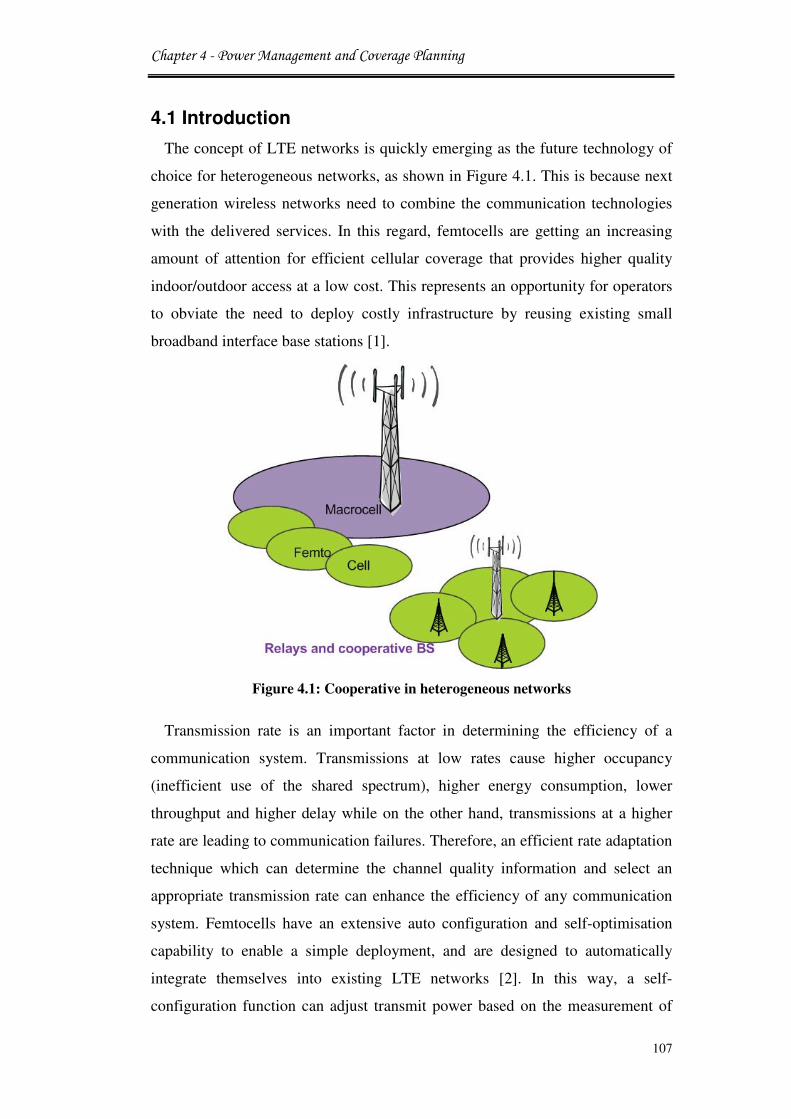
Chapter 4 - Power Management and Coverage Planning
107
4.1 Introduction
The concept of LTE networks is quickly emerging as the future technology of
choice for heterogeneous networks, as shown in Figure 4.1. This is because next
generation wireless networks need to combine the communication technologies
with the delivered services. In this regard, femtocells are getting an increasing
amount of attention for efficient cellular coverage that provides higher quality
indoor/outdoor access at a low cost. This represents an opportunity for operators
to obviate the need to deploy costly infrastructure by reusing existing small
broadband interface base stations [1].
Figure 4.1: Cooperative in heterogeneous networks
Transmission rate is an important factor in determining the efficiency of a
communication system. Transmissions at low rates cause higher occupancy
(inefficient use of the shared spectrum), higher energy consumption, lower
throughput and higher delay while on the other hand, transmissions at a higher
rate are leading to communication failures. Therefore, an efficient rate adaptation
technique which can determine the channel quality information and select an
appropriate transmission rate can enhance the efficiency of any communication
system. Femtocells have an extensive auto configuration and self-optimisation
capability to enable a simple deployment, and are designed to automatically
integrate themselves into existing LTE networks [2]. In this way, a self-
configuration function can adjust transmit power based on the measurement of

Chapter 4 - Power Management and Coverage Planning
108
interference from neighboring base-stations in a manner that achieves roughly
constant cell coverage [3].
This approach involves adapting the transmit power in a collaborative manner.
Once the neighbour responsible for interference is identified, the suffering
femtocell UE could negotiate on the transmit power to be used with this
neighbors. If both parties drop transmits power then this may solve the problem
although compromising the range. This may not be a desirable solution. Rather it
may be an inconvenience, as the UE may have to move closer to the FBS to get
sufficient service. Nonetheless, in the worst-case scenario where there is a high
level of contention for the scarce spectrum, such a solution can at least ensure
service availability/continuity by sacrificing the range. This solution has to be
realised in a collaborative manner to have any significant effect [4].
The transmitted power of a femtocell consists of pilot power and traffic power
(including signalling power and data power). Pilot power determines the
coverage of the cell: high pilot power leads to the large cell coverage and low
pilot power may lead to insufficient coverage. Moreover, the larger the allocated
pilot power, the less the power is left for traffic, which causes throughput
reduction in the femtocell. On the other hand, large pilot power may introduce
high outage probability to neighbouring unregistered mobile users due to
interference. Therefore, pilot power management involves a trade-off between
pilot pollution and coverage [5]. Cognitive operators shrink the organisational
demands to reduce the amount of traffic, the pilot power should be minimised to
leave as much power as possible for traffic channels in order to increase cell
capacity. This leads to an efficient power management which is an important
component of radio resource optimisation [6].
Motivated by what is mentioned above, this chapter focuses on the power
management in order to realise a pilot power configuration technique for the
cognitive access networks. This improves the flexibility of the new cognitive
system in reducing the power of transmission and increase the system resources
competence. In addition, the study considers energy efficiency based on the daily
traffic analysis and the femtocells deployment across the cell sites. The
algorithms and mathematical models given in this chapter help to achieve higher
levels of network re-configurability.

Chapter 4 - Power Management and Coverage Planning
109
4.2 Related Work
The structural design of cognitive femtocell is based on infrastructure-based
overlay LTE network and autonomous sensing of the radio spectrum unused by
the macrocell base stations. A system composed of LTE and femtocells can
improve the network performance by: reducing macrocell traffic, providing
services in locations without signal or with weak coverage, and handling the
local resource management.
Many studies in the literature deal with different methods for pilot power
control management [7]. The goal is to ensure a constant femtocell radius in the
downlink and a low pre-definable uplink impact to the macrocells.
Most of previous work on adaptive pilot power mainly concentrates on the
cognitive radio users with only one type of service requirement, without
considering the scenario with heterogeneous services. While in [8] the authors
was proposed a power allocation scheme to improve the overall system
throughput, defined as the total number of subscribers that can be simultaneously
served and supporting heterogeneous services in cognitive radio environments.
First, the work was classifying the SUs by service requirement with minimum
QoS guarantee. Then was formulated the problem of dynamic channel and power
allocation of CR users as a mixed integer programming problem by design
optimum algorithm.
A similar work can be found in [9], where the femtocell coverage can be
optimised using the information collected during the mobility events of mobile
users to improve the coverage area of femtocell BS and to reduce the
unnecessary mobility signalling. Moreover, a new power control technique is
address as the first step to minimise the interference when the femtocell sharing
the spectrum and using the same frequency band with the macrocell. The authors
in [10] undertook a comprehensive self-organisation model to control the
femtocell power in the co-channel deployment in coexistence with macrocell in a
hierarchical cell structure.
The issues of self-optimised coverage coordination in the femtocell networks
were examined in [11], where a femtocell base station adjusts the transmit power
according to the statistics of the signal strength that is measured at a femtocell
downlink. In [12], cognitive radio UEs can adjust their transmit powers to limit

Chapter 4 - Power Management and Coverage Planning
110
any interference with PU and by considering the individual rate requirements of
each CR. In this way, new adaptive algorithm of a distributed value based
Signal-to-Interference-Noise-Ratio (SINR) at femtocells is employed in order to
improve cross-tier interference at the macrocell due to co-channel impacts. The
scheme involves adapting link budget analysis which enables simple and
accurate performance insights in a two-tier network in a collaborative manner.
However, in [13] CR UEs can update their transmit powers regularly to reduce
interference to PUs, but there is no variations in transmission parameters of
individual CRs were considered.
In [14], the researchers considered layouts featuring varying numbers of
femtocell base stations per cell in addition to conventional macro sites and the
power consumption. This was used as a system performance metric to evaluate
potential improvements of this metric through the use of femtocell base stations.
New research in [15] addresses a joint power and admission control scheme for
cognitive radio network in order to maximise the energy efficiency of the
secondary users and guarantee the QoS of both the PU and the CR. However, the
research was providing both centralised and distributed solutions where the
insight on how a CR user’s interference is influenced by a PU’s is not
considered.
In contrast to these power management approaches, our target is to perform
power control analysis of sub-band occupancy. Authors in [16] investigate the
energy saving potential by exploiting a spatial two-tier network and two original
power metrics for analysing the cellular network. The paper has been analysed
the downlink energy consumption and provide a new energy efficient spectrum
allocation policy in macrocell and femtocell cellular systems to reduce the
downlink energy consumption. The energy consumption and network
performance of the new emerged network are used to quantify the potential of
this feature. Similar investigations with respect to base station densification and
traffic are conducted in [17], where the researcher has tackled the issue of
energy-aware management of cellular access networks. They tried to characterise
the amount of energy that can be saved by reducing the number of active cells in
the access networks during the periods when they are not necessary because the
network traffic is low.

Chapter 4 - Power Management and Coverage Planning
111
4.3 Power Management System
The management approach for power efficiency of 4G radio communications
LTE system using cognitive femtocell is developed as shown in Figure 4.2 to be
a self-organising system, by integrating optimisation and auto-configuration
procedures as explained in this section.
Traditionally, the pilot power of the femtocell base station is setup to fixed
values which means that all mobile users within the coverage area are receiving
the same power irrespective of their relative positions to the base station. While,
adaptive power control proposals suggest that a base station must listen to the
radio environment to the make regular measurements of existing noise and power
levels. Based on these evaluations, the femtocell will adjust the pilot power to a
level that causes only an acceptable amount of interference. In the considered
scenarios, a macro and femtocell base stations are employed to create an adaptive
transmission domains. Provided by intelligent control modules, femtocells can
adapt their coverage size according to the mobile users’ position.
Figure 4.2: Management approach for power efficiency of 4G radio
communications LTE system
The proposed method for adaptive coverage adjustment for femtocell
management is able to steer the coverage power as shown in Figure 4.3, while
the outer limits of the femtocell coverage area remain fixed. In this method, the

Chapter 4 - Power Management and Coverage Planning
112
transmitted power is a function of the client distance from the femtocell base
station and the angle of transmission. Transmission adaptations occur whenever a
mobile leaves the main macrocell area and gets into the femtocell zone. Then, the
femtocell needs to identify the instantaneous position of the mobile to adjust the
power of transmission.
At the first instance, the femtocell power is set to the maximum level denoted
as distance d3 with power transmissions as P3. When active users are close to the
femtocell, it operates self-optimisation and changes the power and coverage to
alleviate power to the levels of P1 at distance d1. Hence, the transmission pattern
is dynamically adapted to attain the most cost effective power savings by
reducing the transmitted power whenever the mobile moves closer to the FBSs.
Figure 4.3: Adaptive coverage adjustment for femtocell management
4.3.1 System Formulation
For each femtocell with one subcarrier, the transmitted power is set to a certain
value that is on average equal to the power received from the management
system at the target cell radius ofr = 30m, depending on the maximum power of
the femtocell P� = 20dBm.
Chapter 4 - Power Management and Coverage Planning
113
In the downlink, both the pilot power and the maximum transmitted power
must be configured. The same approach is also applied for the auto-configuration
of the pilot power to achieve the target range [9, 16]. Here, the transmitted power
from each cognitive femtocell is set to a value that is on average equal to the
power received from the closest macrocell at the target cell radius ofr, subject to
a maximum power ofP�, the femtocells transmitted power can be calculated
in decibels as:
P����� = min�P� + G�θ� − L��d� + L��r���4.1�
where P� is the transmit power of the sector in which the femtocell is located,
and G�θ� is the antenna gain in direction of the femtocell where θ is the angle to
the femtocell with respect to the sector angle, L� is the path loss between the
macrocell BS and the femtocell BS, and d is the distance between them. L��r� is
the line of sight path loss at the target cell radius r (excluding any wall losses).
The initial self-configuration values only present the initial cell coverage
boundaries of a femtocell, which is subject to change due to the installation of
adaptive power control unit. In the uplink, the mobile user’s power is limited to a
value limiting the aggregate interference of all femtocell mobile users to the
closest macrocell, thereby ensuring the uplink of the macrocell is not degraded
significantly.
4.3.2 Proposed Scheme: Adaptive Pilot Power Control
In this section, novel algorithms are implemented in the femtocell base station
to control cell coverage. The goal is to design algorithms that periodically update
the pilot power configuration based on each femtocell’s user signal strength and
global traffic delivery in the network as shown in Figure 4.4.
Each femtocell is assumed to have a power value that guarantees a given
received signal strength to its active attached users. This scheme is assisted by
standard measurement reports, which are performed by the users and feedback to
the cells for channel quality estimation purposes. The objective behind this is to
find the optimal pilot power vector !"#which determines the cell radius $%,' for
each femtocell(%, such that:

Chapter 4 - Power Management and Coverage Planning
114
Maxr�4.2� d, ≤ ri = 1,2, …………… . . , N
0 ≤ p, ≤ p�,,i = 1,2, …………… . . , N
where r is a radius of femtocell BS coverage. The above optimisation is
equivalent to a Max-Min problem: max-min d,, i = 1,2, ……… ,N, which
maximises the minimum femtocell radius in the network. P�,defines the
maximum pilot power in each cell i which constrains the cell radii solved from
Equation 4.2. The power is adjusted at a vector of P, corresponding to each cell
radius ofd,.
Figure 4.4: Femtocell coverage as a function of mobile distance
The other challenge of power optimisation is to save more power than other
traditional femtocells in the area which they have fixed transmitted power.
According to equation 4.2, all users’ deployed access points cooperate to smooth
out the potential big variance of cell sizes in an arbitrary infrastructure topology.
This dissimilarity is much more adaptive than setting up a constant cell radius of
(10) meters for all femtocells as studied in previous work [7]. Now, the function
Chapter 4 - Power Management and Coverage Planning
115
%,' is introduced to replace the radius expression d, in equation 4.2 and the
original problem becomes:
Maxr�4.3� %,' ≤ r,i = 1,2, …………… . . , N 0 ≤ p, ≤ p�,i = 1,2, …………… . . , N
The function of %,' maps the adjustable power vector !"#to each of the cell
radiir,. This replacement can be used because a particular pilot power allocation
pattern !"# uniquely determines each femtocell size in the network.
In more detail, user (12 sends a measurement report to its serving femtocell
base station 345regularly at 6��789���:�time intervals. The femtocell user
report indicates the received signal strength ;<<=>?,12@%ABC , measured by a user (12
in the pilot of femtocell 345. After receiving reports from all its connected mobile subscribers, the femtocell
then identifies which one is the strongest signal. It should be noted that since
femtocells are likely to uniformly distribute their power among all subcarriers in
order to avoid large average to peak power ratios [18]. The femtocell BS adjusts
its transmitted power PDE:�Ffor each subcarrier according to the following
equation:
PDE:�F =G '"HH=I = P����NJK '"HBAL +�RSSOP,JK�9 − RSSOP,JKQ,R�� �S�4.4�
where '"HH=I is the maximum power of the femtocell BS, P���� is denote to the
total power radiated from femtocell BS to all subscriber in its domain and, T12 represents the total number of existing subcarriers. '"HBAL denotes the current power radiated to each subcarrier; ;<<=>?,12@%ABC is the
average received signal strength estimated for the active user (derived using

Chapter 4 - Power Management and Coverage Planning
116
measurement reports); RSSOP,JK�9 is the targeted received signal strength by the
cell for the farthest user.
Algorithm 4.1: Pilot power control proposed scheme
1: /* Calculate the avg. power of signal linked with transmitted PKT*/
2: femtocell not active
3: surrounding awareness
4: any active user
5: wake up triggered pipeline
6: Received Signal Strength(RSS) from mobile
7: check the channel statue
8: if Channel is already occupied then
9: adapt to another channel
10: end if
11: pilot power 'H=I
12: if user in coverage
13: self-power optimisation ( =LU!"#)
14:
PDE:�F =G '"HH=I = P����NJK '"HBAL +�RSSOP,JK�9 − RSSOP,JKQ,R�� �S
15: end if
16: if (d>r)
17: go to (2)
18 else
19 if (d≤ r)
20 network coverage
21 end if
22 end if
This power control runs on a regular basis on a frequency of femtocell BS in
order to adapt the femtocell coverage to any kind of environment and to cope
with the mobility of users within the offices. The proposed scheme for adaptive

Chapter 4 - Power Management and Coverage Planning
117
power control adjustments is given in Algorithm 4.1. Mobile users have the
ability to wake up the femtocell by transmitting data signals. This allows the
femtocells to determine the SNR for the received request based on values
obtained from mobile user communications as shown in Algorithm 4.2.
Algorithm 4.2: Signal to Noise Ratio
1: /*Compute the SNR for the given packet*/
2: get the packet power level
3: get the interference noise
4: Calculate SNR= (RECEIVED POWER / NOISE)
Normally, the wake-up signal could be received by more than one femtocell as
they detect the same mobile signal strength. Then, the Radio Network Control
(RNC) will be responsible to decide the femtocell that should be waked to start
operation. However, when the femtocell is chosen to serve, its pilot power should
be at the maximum value P���� to ensure that the mobile user is covered. After
that, and based on mobile position, the femtocell can adaptively update pilot
power to reach the optimum value in order to save power. The power adjustment
process keeps on until utilising the best coverage or the mobile leaves the
maximum coverage area.
4.3.3 Radio Transceiver Pipeline Models
This section describes the functionality and implementation of the power
control model in the radio transmitter pipeline. The model is developed using a
modified MAC layer and PHY pipeline stages to configure the femtocell
transmitted power. Advance OPNET version 17.1 simulations with a developed
C++ system code were used to implement the network performance with the
femtocell self-optimisation coverage model. OPNET [19] provides a
comprehensive improved environment that supports the modeling of wireless
communication networks and distributed systems.
The Simulation Kernel in OPNET has Transmission Data Attributes (TDA) to
supply transmission feature with access to a minimum standard set of values in
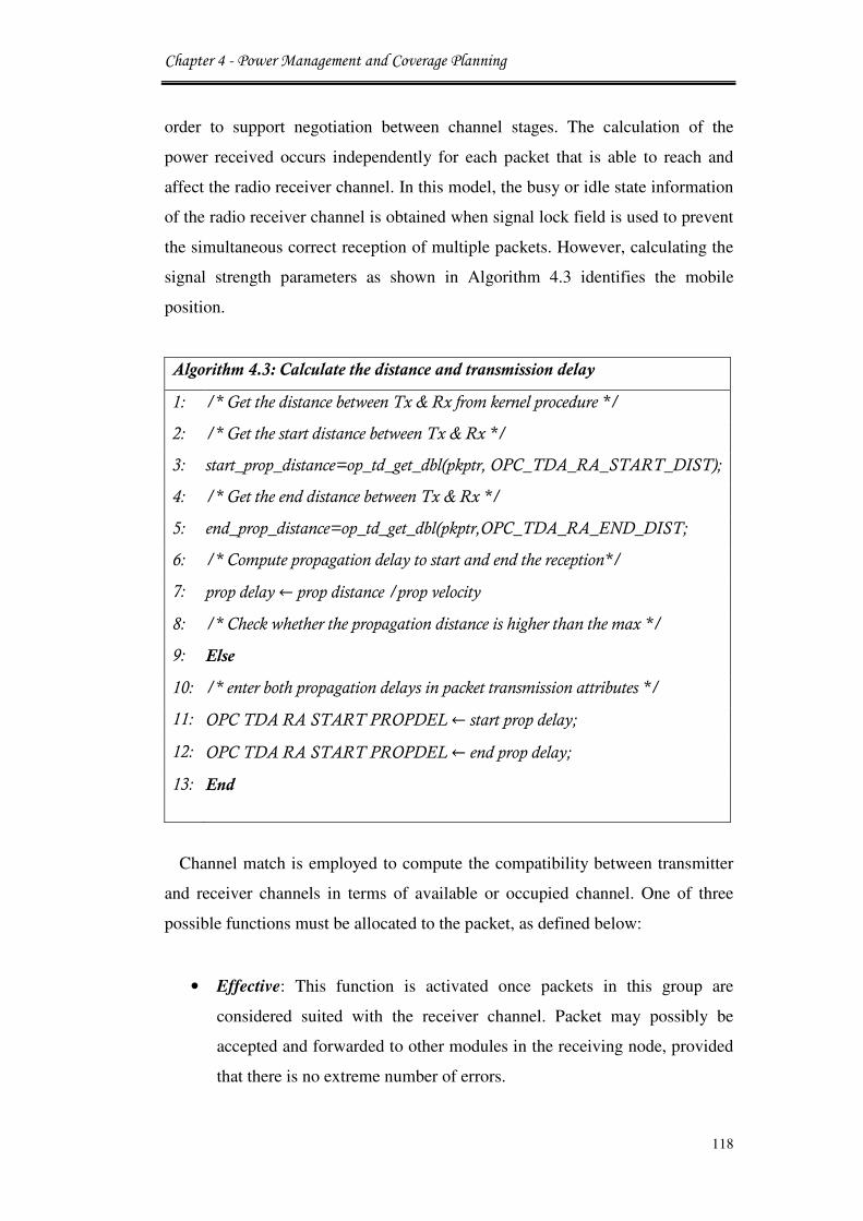
Chapter 4 - Power Management and Coverage Planning
118
order to support negotiation between channel stages. The calculation of the
power received occurs independently for each packet that is able to reach and
affect the radio receiver channel. In this model, the busy or idle state information
of the radio receiver channel is obtained when signal lock field is used to prevent
the simultaneous correct reception of multiple packets. However, calculating the
signal strength parameters as shown in Algorithm 4.3 identifies the mobile
position.
Algorithm 4.3: Calculate the distance and transmission delay
1: /* Get the distance between Tx & Rx from kernel procedure */
2: /* Get the start distance between Tx & Rx */
3: start_prop_distance=op_td_get_dbl(pkptr, OPC_TDA_RA_START_DIST);
4: /* Get the end distance between Tx & Rx */
5: end_prop_distance=op_td_get_dbl(pkptr,OPC_TDA_RA_END_DIST;
6: /* Compute propagation delay to start and end the reception*/
7: prop delay ←prop distance /prop velocity
8: /* Check whether the propagation distance is higher than the max */
9: Else
10: /* enter both propagation delays in packet transmission attributes */
11: OPC TDA RA START PROPDEL ← start prop delay;
12: OPC TDA RA START PROPDEL ← end prop delay;
13: End
Channel match is employed to compute the compatibility between transmitter
and receiver channels in terms of available or occupied channel. One of three
possible functions must be allocated to the packet, as defined below:
• Effective: This function is activated once packets in this group are
considered suited with the receiver channel. Packet may possibly be
accepted and forwarded to other modules in the receiving node, provided
that there is no extreme number of errors.

Chapter 4 - Power Management and Coverage Planning
119
• Noise: This function is employed to categorise the packets whose data
content cannot be received, but that have an impact on the receiver
channel’s performance by causing interference.
• Disconnect: If a transmission is determined to have no effect on a
receiver channel’s status. The Simulation Kernel will then crack the link
between the transmitter and receiver channels for this particular
transmission.
The channel match states are determined as shown in Algorithm 4.4.
Algorithm 4.4: Channel match statues
1: /* Check the PKT status */
2: if (TX FREQ >= RX FREQ + RX BW) || (TX FREQ + TX BW <=
RX FREQ) then
3: set channel match statue to disconnect
4: else
5: if (TX FREQ ! = RX FREQ) || (TX BW! = RX BW)
6: Set match status to noise
7: else
8: Set match status to effective
9: end if
Algorithm 4.5 gives the power calculation of the mobile signals arrived
packets.
Algorithm 4.5: Power level of signal arriving at receiver
1: /* Compute the average received power in Watts */
2: /* signal associated with a transmitted packet */
3: if (op_td_is_set (PKPTR, OPC_TDA_RA_RCVD_POWER)) then
5: path_loss = op_td_get_dbl (PKPTR, OPC_TDA_RA_RCVD_POWER);

Chapter 4 - Power Management and Coverage Planning
120
In general, the calculation of received power is based on factors such as the
power of the transmitter, the distance separating the transmitter and the receiver,
the transmission frequency, and transmitter and receiver antenna gains. If
transmitter and receiver are the same then calculations are unnecessary and the
antenna gain is set to zero. Else, the gain is obtained from the kernel procedure
[P_TBL_PAT_GAIN (PAT_TBL_PTR, POLAR, AZIMUTH)] which provides
particular antenna direction to gain value corresponding to that direction.
System level simulations will help to examine performance of the new
femtocell algorithms in different scenarios. On the other hand, it will assist to
understand the performance of different strategies, e.g. power efficiency and
packets delivery times.
4.4 Simulation
The simulation project was created to evaluate the performance of the
proposed algorithms for power control. The model is tested with a number of
femtocells, where each femtocell serves a maximum of four subscriber stations.
Figure 4.5 shows the scenario setup. An open access network is used where
mobile users are linked with the nearest femtocell base station; the signal is very
weak from macrocell base station.
Figure 4.5: Sample of power management project in OPNET17.1

Chapter 4 - Power Management and Coverage Planning
121
The performance of the proposed power control algorithm is calculated for 25
mobile end-users. Then the system was tested for 20, 40, 60, and 80% femtocells
with activated power transmissions. These subscribers were deployed randomly
at the macrocell-femtocell network domain. To validate the performance of the
proposed adaptive pilot power configuration of 20dBm, the simulation is
compared with fixed value of femtocell transmitted power, as in [7, 9]. The
proposed algorithm dynamically determines the pilot power allocation according
to the nature of cognitive network that can dynamically change the infrastructure
topology in order to optimise the spectrum management. The network parameters
were set as shown in Table 4.1.
Table 4.1: System parameters for LTE-femtocell network
Parameters Value
Simulation time 5 mint
Transmit power LTE
Transmit power femto
40dBm
20dBm
Bandwidth 5MHz
Antenna gain macro/femto/mobile (14/5/0) dB
Thermal noise density -174 dBm/Hz
Noise figure in mobile 9 dB
Femto /mobile antenna pattern Omni
Macro/femto shadow fading 4dB, 8dB
Noise density -80dBm/Hz
Wall loss 15dB
Path loss outdoor 70dB
The simulation was conducted to examine the new power control approach that
is connected to an IP cloud that represents the backbone Internet.
Figure 4.6 shows that the power consumption for the aggregate traffic loads of
high and low profiles of variable numbers of cognitive femtocells. The
installation of the new proposed scheme results in major improvement in system
performance by reducing the values of system power consumption. This is due to
the fact that the optimised power allocation scheme creates effective coverage
areas that identify the exact UE location without any need to transmit power
beyond the actual mobile location. The figure shows that high traffic profile
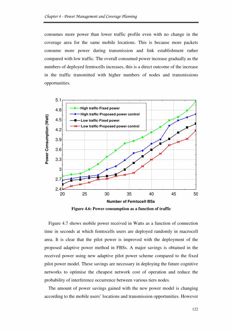
Chapter 4 - Power Management and Coverage Planning
122
consumes more power than lower traffic profile even with no change in the
coverage area for the same mobile locations. This is because more packets
consume more power during transmission and link establishment rather
compared with low traffic. The overall consumed power increase gradually as the
numbers of deployed femtocells increases, this is a direct outcome of the increase
in the traffic transmitted with higher numbers of nodes and transmissions
opportunities.
Figure 4.6: Power consumption as a function of traffic
Figure 4.7 shows mobile power received in Watts as a function of connection
time in seconds at which femtocells users are deployed randomly in macrocell
area. It is clear that the pilot power is improved with the deployment of the
proposed adaptive power method in FBSs. A major savings is obtained in the
received power using new adaptive pilot power scheme compared to the fixed
pilot power model. These savings are necessary in deploying the future cognitive
networks to optimise the cheapest network cost of operation and reduce the
probability of interference occurrence between various tiers nodes.
The amount of power savings gained with the new power model is changing
according to the mobile users’ locations and transmission opportunities. However
20 25 30 35 40 45 502.4
2.7
3
3.3
3.6
3.9
4.2
4.5
4.8
5.1
Number of Femtocell BSs
Po
wer
Co
nsu
mp
tio
n (
Watt
)
High traffic-Fixed powerHigh traffic-Fixed power
High traffic-Proposed power controlHigh traffic-Proposed power control
Low traffic-Fixed powerLow traffic-Fixed power
Low traffic-Proposed power controlLow traffic-Proposed power control

Chapter 4 - Power Management and Coverage Planning
123
in some femtocells, there is more than 12 dB reduction in the transmitted pilot
power using the proposed scheme.
Figure 4.7: Mobile power received as a function of connection time
The average time delay for end-to-end transmissions is represented in Figure
4.8. The given curves show the system performance before and after using the
power adaptation algorithm. The analysis combines the fixed pilot power and the
proposed adaptive pilot power methods to show the overall improvement in time
delay while adjusting the power of the system. The overall time delay is reduced
by approximately 30% at each individual case by using the new adaptive power.
This is due to the fact that there will be more opportunities for spectrum access,
link formulation, and lower interference while more femtocells are set to use
optimised transmission sites. This scenario analysis considers only the time of
packets delivery between femtocells and their end-users. This means that the
proposed model offers an improved coexistence between femtocell network
wireless environments that share the same resources and bandwidth channel
frequencies. On the other hand, it is understood that the proposed algorithm
greatly outperforms the fixed pilot power scheme in terms of much lower outage
probability of public UEs.
0 30 60 90 120 150 180 210 240 2700
0.1
0.2
0.3
0.4
0.5
0.6
0.7
0.8
0.9
1
UE
Po
wer
Rece
ived
(W
)
80% Deployed FBS - Fixed power80% Deployed FBS - Fixed power
80% Deployed FBS - Proposed power control80% Deployed FBS - Proposed power control
60% Deployed FBS - Proposed power control60% Deployed FBS - Proposed power control
60% Deployed FBS - Fixed power60% Deployed FBS - Fixed power
40% Deployed FBS - Proposed power control40% Deployed FBS - Proposed power control
40% Deployed FBS - Fixed power40% Deployed FBS - Fixed power
20% Deployed FBS - Fixed power20% Deployed FBS - Fixed power
20% Deployed FBS - Proposed power control20% Deployed FBS - Proposed power control
System connection time (sec)
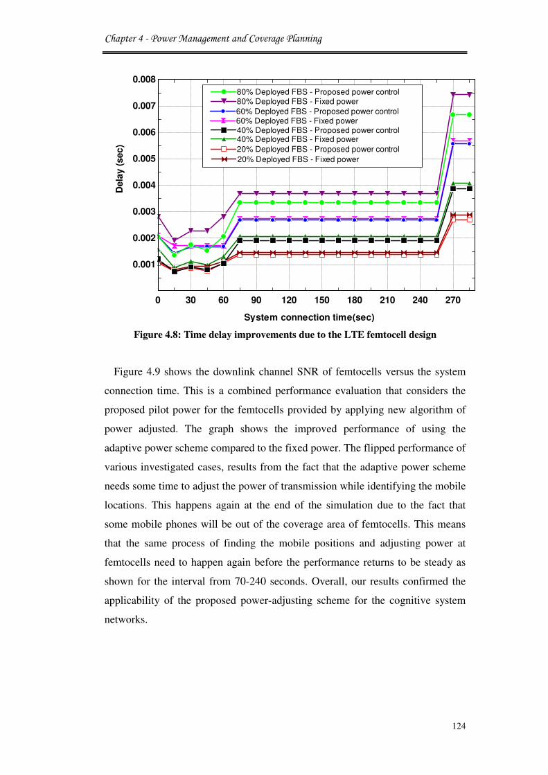
Chapter 4 - Power Management and Coverage Planning
124
Figure 4.8: Time delay improvements due to the LTE femtocell design
Figure 4.9 shows the downlink channel SNR of femtocells versus the system
connection time. This is a combined performance evaluation that considers the
proposed pilot power for the femtocells provided by applying new algorithm of
power adjusted. The graph shows the improved performance of using the
adaptive power scheme compared to the fixed power. The flipped performance of
various investigated cases, results from the fact that the adaptive power scheme
needs some time to adjust the power of transmission while identifying the mobile
locations. This happens again at the end of the simulation due to the fact that
some mobile phones will be out of the coverage area of femtocells. This means
that the same process of finding the mobile positions and adjusting power at
femtocells need to happen again before the performance returns to be steady as
shown for the interval from 70-240 seconds. Overall, our results confirmed the
applicability of the proposed power-adjusting scheme for the cognitive system
networks.
0 30 60 90 120 150 180 210 240 270
0.001
0.002
0.003
0.004
0.005
0.006
0.007
0.008
Dela
y (
sec
)
System connection time(sec)
60% Deployed FBS - Fixed power60% Deployed FBS - Fixed power
80% Deployed FBS - Proposed power control80% Deployed FBS - Proposed power control
60% Deployed FBS - Proposed power control60% Deployed FBS - Proposed power control
20% Deployed FBS - Fixed power20% Deployed FBS - Fixed power
40% Deployed FBS - Proposed power control40% Deployed FBS - Proposed power control40% Deployed FBS - Fixed power40% Deployed FBS - Fixed power
80% Deployed FBS - Fixed power80% Deployed FBS - Fixed power
20% Deployed FBS - Proposed power control20% Deployed FBS - Proposed power control

Chapter 4 - Power Management and Coverage Planning
125
Figure 4.9: SNR improvements due to the LTE femtocell design
4.5 Power Consumption Estimation
In this section, the coverage parameters that affect the energy efficiency and
cell coverage area are investigated for future cognitive networks that employ
femtocell stations. This is supported by traditional concept of cell edge, cell area
type information, and propagation models. In addition, the network's power
consumption is characterised (in watts per unit area) for given coverage in order
to optimise the BS cell radius with respect to mentioned factors.
4.5.1 Cell Coverage Area
The coverage nodes provide the sufficient field strength for the guaranteed
service at cell edges in case of low traffic. If the traffic load increases and the
assured service level cannot be provided, then femtocell nodes should be
activated and power adapted back to the full-coverage mode.
Typically, umbrella macrocells are responsible for providing coverage for
difference-sized areas like rural and urban as shown in Figure 4.10. In the some
countries that have vast population areas can be covered by large macro cells
operating in a low frequency band if available [20]. The cell coverage area is
assumed to be hexagonal depends on the site configuration.
0 30 60 90 120 150 180 210 240 27026
28
30
32
34
36
38
40
Sig
na
l to
No
ise R
ati
o (
dB
)
System connection time(sec)
80% Deployed FBS - Fixed power80% Deployed FBS - Fixed power
80% Deployed FBS - Proposed power control80% Deployed FBS - Proposed power control
60% Deployed FBS - Proposed power control60% Deployed FBS - Proposed power control
60% Deployed FBS - Fixed power60% Deployed FBS - Fixed power
40% Deployed FBS - Proposed power control40% Deployed FBS - Proposed power control40% Deployed FBS - Fixed power40% Deployed FBS - Fixed power
20% Deployed FBS - Fixed power20% Deployed FBS - Fixed power20% Deployed FBS - Proposed power control20% Deployed FBS - Proposed power control

Chapter 4 - Power Management and Coverage Planning
126
Figures 4.10: Networks node coverage for different size areas
The site coverage area of LTE can be calculated as following [21]:
W7,�� = �πdY�No. ofSectors�4.5�
The macrocell BS is considered as a regular grid of sites represented by the
diameterd.
Figure 4.11 shows a three hexagonal cell models: Omni-directional site, Bi-
sector site and Tri-sector site. Therefore, the number of sites to be deployed can
be easily calculated from the cell area Wa�RR and using the deployment area
siteA7,�� :
N7,��,a�O�9P� = W7,��Wa�RR �4.6�
Where is N7,��,a�O�9P� is number of coverage sites. The macrocell base station
network is modeled as a regular grid of sites symbolised by the site distanceD,
generating equally sized hexagonal cell structures of side lengthR = e√g.

Chapter 4 - Power Management and Coverage Planning
127
Figure 4.11: Hexagonal cell site types
These approaches are suitable for LTE macrocell/femtocell overlaid cell
structure, where femtocell coverage must be controlled so it does not interfere
with the outdoor macrocell. In order to achieve this goal, a coverage coordination
scheme that is based on the numerical analysis of the signal strength and
interference power measured at a femtocell downlink. This scheme comprises
both the self-configuration and self-optimisation of femtocell pilot transmits
power. With a self-configuration function, a femtocell BS initiates it’s transmit
power based on the measurement of interference from neighboring BSs in a
manner that achieves a roughly constant cell coverage [22].
In the following calculations, the term cell is used to refer to the hexagonal
region of one site. Each cell might be further divided into several sectors
accordingly served by many co-located macro base stations as shown in Figure
4.12. For given inter site distance, the cell size area hijkkcalculates as following
[23]:
Wl"AA =√32 �D/1000�YKmY�4.7�
The optimal cell size can be achieved once the QoS requirements of throughput
and time delay are satisfied. This study considers a two-tier cellular network
composed of overlaid macrocells and femtocells base stations in which both cells
use the same frequency channel.

Chapter 4 - Power Management and Coverage Planning
128
Figure 4.12: Regular grid of base stations and corresponding cell geometry with
inter site distance ISD and cell area hijkk
A femtocell BS is located at the edge of a LTE macrocell with radius (r). Both
BSs users are equipped with an omni-directional antenna. The femtocell BS
creates cell coverage which is adaptively adjusted by the proposed transmits
power control in order to correspond to the coverage area. The transmitting
power control is composed of two steps; where the femtocell BS initially self-
configures its power and self-optimises cell coverage by using transmit power
control based on the measurements of radio environments.
4.5.2 Area Spectral Efficiency
Spectral efficiency is a key performance parameter in cellular mobile radio
networks that is the optimum spectrum used to provide a large amount of data at
a specific bandwidth. It is defined for each location, as the ratio of throughput to
the bandwidth of a user under the assumption of one single subscriber in a cell.
According to the Shannon equation the maximum spectral efficiency is given by
[24]:
Sppqr$stp((uqupvqw = xyzY {1 + <T|�4.8�

Chapter 4 - Power Management and Coverage Planning
129
where ~� is the signal to noise ratio.
In this study, area spectral efficiency is defined as the average of the spectral
efficiency with respect to uniformly distributed location of users in the network
per unit area. As the objective of the study is to quantify the energy saved due to
the femtocell deployment, a traffic energy model is used based on the typical
standards of various base transceiver station models. The throughput model is
represented by the following equation:
TP = ASE ∗ BW ∗Wl"AA�4.9�
Where TPis referred to as the throughput,ASE is the area spectral efficiency BW is cell bandwidth, and Wa�RR denotes the area cell size. One measure of area
spectral efficiency of shared macrocell and femtocell is in terms of
bit/sec/Hz/macrocell area. It should be noted that area spectral efficiency is
expressed in bits/sec/Hz/kmY. Since Hertz (Hz) is the inverse of time, it is also
correct to express it in bits/kmY. Thus ASE is the mean of all the users in the
system divided by the cellular area and it would be different from individual data
rates [24].
4.6 Power Consumption Modeling
In this section, a power consumption modeling is proposed to evaluate the
power management in a LTE cellular network with femtocell BSs deployment.
The power consumption is assumed from base stations aspect that has linear
relationship to the utilisation of radio resource. Moreover, power use of typical
base station is as follows: Power supply, cooling fans, central equipment,
cabling, transceiver idling, combining/duplexing, power amplifier, transmit
power, and transceiver power conversion.
A developed mathematical model is proposed to assess the power performance
of femtocell framework design. A system model approach is essential since it is
useful to make decisions based on logical assessment and it also supports
performing the desired analysis that was previously applied in [17] to describe
the macrocell base station power sharing. The goal of the proposed power
consumption model is to make input parameters available for the simulation of

Chapter 4 - Power Management and Coverage Planning
130
total power consumption in 4G cognitive communication networks. The cell
power is formulated by [25]:
Pa�RR�F��� = ��Q�9��9 + �η ∗ P��,��K��4.10�
where��Q�9��9 represents the power operator, η denotes the cell load/capacity
that may vary between 0.1 and 0.9 depending on the user’s capacity and radio
interface configuration, and term P�is the power that is needed to create required
transmission power in the antenna output. The term capacity contains all capacity
independent power that is needed to operate the BS. The relation between the
average radiated power P�,��K and a site's power consumption is linearly
modeled for macro sites by [25], where it is linearly modeled for both LTE and
femtocell sites by:
P��K = N7�a. N:��∀��K. P�,��K +B��K��4.11� P��� = ∀���. P�,��� +B����4.12�
where N7�a denotes the number of sectors per macrocell, N:� the number of
antennas per sector. The coefficients ∀��K and ∀��� account for the power
consumption that scale with the average radiated power. The transmit power and
independent power offsets B��K and B���are both mainly impacted by the power
spent for signal processing [26].
It should be noticed that in the case of LTE sites it is also impacted by site
cooling due to hardware components contributing to thermal radiation regardless
of the transmit power. The studied power modeling does not include the energy
consumption used by other elements at the base station for that site such as:
backhaul, antenna feeder cables, cooling, and backup power systems.
In order to measure the power consumption of a cognitive network relative to
its area Area Power Consumption (APC) is used. This is defined as the average
power consumption per cell divided by the cell area and is measured in watts per
square kilometer [27]. The area power consumption of a network APC can be
expressed mathematically as:

Chapter 4 - Power Management and Coverage Planning
131
Pa�:78�Q�,�: = 1Wa�RR � %%∈�� �4.13�
Where the power consumption portion P, of the site serving sector W, is
determined by the following equation:
P, =�1 N7�a� . P��KifW,isamacrocellsector,P���ifW,isafemtocellsector. �4.14�
Note that in (4.14) only the power consumption figures % of sites are
considered as long as they serve sectors belonging to the reference cell. In the
same way the area Wa�RR corresponds to this reference cell and then expanded to
the whole investigated site area.
4.7 System Power Consumption Evaluated
4.7.1 Numerical Results
In this section, the numerical analysis of system networks is presented in order
to obtain the optimum ISD value. Analyses are performed rather than simulations
due to the fact that statistics allow better evaluations for the exact coverage areas
than overlapped transmission domains in simulations. The model scenario
consists of one macrocell base station with variable grid of sites symbolised by
the site distance D, which ranges between 500-2000 meters, to generate equally
sized hexagonal cell structures of side length R. Cell area needs to be covered by
95% for each considered site distance and base station domains of macro and
femtocells. Mobiles are placed randomly at the edge of a macrocell area in a
uniform distribution. Femtocell sites are assumed to support a circular area of
radius 30m and are positioned at the cell edges where the signal levels of the
macro LTE units can be expected to be very low. The numerical analysis is based
on the users located outdoors only. The spectral efficiency (ASE) is assumed to
be 6bit/s/Hz according to equation 4.10. The power model parameters are
selected as the values resulting in equation 4.15, assuming that the coefficients of
power consumption are ∀��K=3.8, B��K=68.8W, ∀���=6.3, B���=0.5W. The
power consumption is calculated according to the equation 4.14.
The area power consumption analysis is given as a function of the inter site
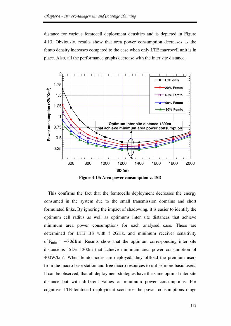
Chapter 4 - Power Management and Coverage Planning
132
distance for various femtocell deployment densities and is depicted in Figure
4.13. Obviously, results show that area power consumption decreases as the
femto density increases compared to the case when only LTE macrocell unit is in
place. Also, all the performance graphs decrease with the inter site distance.
Figure 4.13: Area power consumption vs ISD
This confirms the fact that the femtocells deployment decreases the energy
consumed in the system due to the small transmission domains and short
formulated links. By ignoring the impact of shadowing, it is easier to identify the
optimum cell radius as well as optimums inter site distances that achieve
minimum area power consumptions for each analysed case. These are
determined for LTE BS with f=2GHz, and minimum receiver sensitivity
ofP�,: = −70dBm. Results show that the optimum corresponding inter site
distance is ISD= 1300m that achieve minimum area power consumption of
400W/km2. When femto nodes are deployed, they offload the premium users
from the macro base station and free macro resources to utilise more basic users.
It can be observed, that all deployment strategies have the same optimal inter site
distance but with different values of minimum power consumptions. For
cognitive LTE-femtocell deployment scenarios the power consumptions range
600 800 1000 1200 1400 1600 1800 2000
0.25
0.5
0.75
1
1.25
1.5
1.75
2
Po
wer
co
nsu
mp
tio
n (
KW
/Km
2)
ISD (m)
LTE onlyLTE only
20% Femto20% Femto
40% Femto40% Femto
60% Femto60% Femto
Optimum inter site distance 1300m that achieve minimum area power consumption
80% Femto80% Femto

Chapter 4 - Power Management and Coverage Planning
133
between 800-1270W/Km2, which is considerably less than the power consumed
in the traditional services delivered by the macro LTE base station. Thus, the
femtocell deployment reduces the power consumed in the system. However,
femtocell base stations are not able to increase the optimum inter site distance for
the site under coverage.
The results are compared with the research that has been done in [26], it is clear
that the new model is improving the area power consumption with a logical and
applicable approach by using developed power model. The power consumption
for higher densities of deployed femtocell is decreasing for the same ISD value.
The lowest power for ISD occurs at 1300m for the LTE, and then (20%, 40%,
60%, and 80%) of deployed femtocells respectively, where 90% coverage is
maintained in all cases. This raises a new discussion of deploying femtocells
quickly into the cognitive networks.
4.7.2 Simulation Results
Many traces are generated with a variety of number of femtocells in LTE
macrocell area in order to measure packet delivery fluctuations in radio links.
The path loss calculation could be by using COST231 Hata model [28] as shown
in Figure 4.14. This model is normally used for carrier frequencies between 1500
and 2000 MHz. The propagation model describes the average signal propagation
in that environment, and it converts the maximum allowed propagation loss in
dB to the maximum cell range in kilometers.
Figure 4.14: Okumura–Hata model
The total downlink throughput delivered from LTE layer to the higher layers in

Chapter 4 - Power Management and Coverage Planning
134
bits/sec for cognitive system performance is illustrated in Figure 4.15. The
throughput is collected by all the UEs in the network systems. Here, we can
clearly observe that LTE network at a certain size does not necessarily provide
higher system throughput capabilities. In this model there is an increase in
throughput figures by increasing the femtocell numbers and the peak throughput
decreases noticeably after 275 sec. The farthest mobile to the base stations, the
higher the probability of loss of line of sight communications. Also, the same
holds for line of sight between mobile and interfering base stations. Hence, the
SNR at a mobile is getting better the smaller base stations’ size due to an
increasing number of base stations generating significantly low load and high
throughput. Obviously, there is a max peak throughput realising inter site
distance, which corresponds to about 1300m in our example.
Figure 4.15: Downlink throughput delivered from LTE layer
From this figure it is shown that cognitive users in the transmission domain do
not show any drop after the peak value of throughput. This is because that
macrocell network is not fully loaded by cognitive users and the increase in
traffic does not reach the threshold yet, which basically does not show their
offloading nature. In the LTE only when there are no femtocell nodes, it is shown
that great degradation in the throughput occurs when cognitive users are in the
50 75 100 125 150 175 200 225 250 275 3000
30000
60000
90000
120000
150000
180000
210000
240000
270000
300000
System connections time (Sec)
Systs
em
Do
wn
lin
k T
hro
ug
hp
ut
(bit
s/s
ec)
40% Femto40% Femto
60% Femto60% Femto
80% Femto80% Femto
20% Femto20% Femto
LTE onlyLTE onlyThroughput decrease

Chapter 4 - Power Management and Coverage Planning
135
range, which gives a clear indication of advantage of femtocell deployment.
Figure 4.16: Impact of system load
Figure 4.16 shows that a smooth load transfer has been achieved using the new
adaptive scheme where femtocells transmit at the maximum power at all times
and both macrocell and femtocells BSs are using the same frequency band. On
the other hand, load convey is measured from the time the traffic arrives to the
LTE layers of the BS until it is delivered to the higher layer of the corresponding
UEs with/without FBS. It is observed that the load performance is highly
sensitive to the traffic increase in cells when the number of femtocell is
increased. Therefore, more network stability and throughput advantages can be
achieved with femtocell deployment.
The performance of average end-to-end packet transmission delay is shown in
Figure 4.17. Clearly, there is an increase in connection time results in an increase
the average packet time delay. However, an average of 20% throughput gain is
achieved by the increased the number of femtocell BSs with in macrocell area
within the bounded delay of 224µs. This is because the fact that the packet
retransmissions caused by the MAC layer packet collision is successfully
reduced by using the new proposed algorithm.
The simulation result of the pilot power algorithm supports the observation
75 100 125 150 175 200 225 250 275 3000
2000
4000
6000
8000
10000
12000
System connections time (Sec)
Lo
ad
(b
its/s
ec)
60% Femto60% Femto
80% Femto80% Femto
40% Femto40% Femto
20% Femto20% Femto
LTE onlyLTE only
The load in macrocell sites is decreased by adding femtocells

Chapter 4 - Power Management and Coverage Planning
136
result in the previous section. The proposed pilot power based requirement
decision is not helpful to avoid packet drops. On the other hand, the result resents
that enormously large amount of transmission power is needed for the data rate
requirement.
Figure 4.17: Average system end to end packet delays
4.8 Site Energy Consumption Modeling
The objective of this power model is to examine cognitive system based on the
calculated power consumptions and to define an appropriate energy modeling
that is saving energy. Therefore, a site power modeling is introduced based on
typical values that consider integrated base station system for all users at a site.
The model of the power consumption for a site system can be represented by the
following equation [29]:
P7,�� = Na�RR. [P�Q�9��9 + �η ∗ P��]�4.15�
Where Na�RRrefers to the number of cells in the site. η is represent the cell load,
and P� is refer to the power transmit of the macrocell BS. The site energy
50 75 100 125 150 175 200 225 250 275 3000
0.005
0.01
0.015
0.02
0.025
0.03
0.035
System connections time (Sec)
En
d t
o E
nd
Dela
y (
sec)
60% Femto60% Femto
80% Femto80% Femto
40% Femto40% Femto
20% Femto20% Femto
LTE onlyLTE only

Chapter 4 - Power Management and Coverage Planning
137
consumption estimations for a system with a real time application can be
computed at a certain time period T as: E7,�� = Na�RR. �P�Q�9��9 + �η ∗ P���T�4.16�
Impact of temporal capacity variations is investigated in [30]. The energy usage
over time T (seconds) in LTE macrocellular network is given by:
E���,��K = N7,��.E7,��. +N78�. E78� + E����9�4.17�
This is a precise definition for the energy consumed in all macrocell and sub-
macrocell BSs. Where N7,��and E7,�� refer to number of BS sites and energy
consumed by single BS site respectively, N78�refers to number of subscribers
and E78� refer to the energy consumed by single user and the last term contains
energy consumed by other mobile network elements such as the core network
elements and radio network controllers in OFDM. When cognitive femtocell
systems are deployed in such a network, the energy utilised by the network is
given by [31]: E���,����� = N7,��.Na�RR. �Ea�RR + N�. P�. T��4.18�
Where N� the number of femtocell in each macrocell network and P� is the
power usage of the femtocell BS over timeT.
4.9 Efficient Energy Scenario
In this cognitive system model, the estimation of the change in the network
load and configuration is studied to see how that may affect the energy
consumption level. The ISD is assumed to be fixed and the total number of cells
is 3 so that interferences from other cells are considered up to two-tiers. The
performance of a LTE is evaluated only for the cell centre, while cognitive
femtocells are distributed throughout the edge of the cell. Macrocell ISD is the
optimum value 1.3Km that has been gained from previous numerical
calculations, and femtocell radius is assumed as 30 meters. Handover between a
macrocell and a femtocell is not considered, so the performances of macrocell
UEs and femtocell UEs are evaluated independently. As a performance measure

Chapter 4 - Power Management and Coverage Planning
138
we will use the daily energy consumption per square kilometer (kWh/KmY) is
used in the network, expressed as follows [30, 31]:
E A� = �N7,��:�F.Na�RR. �P�Q�9��9 +η:�F. P�� N7,��.W7,��⁄ � ∗ 24h+ �Na�RR. N�. P� W7,��⁄ � ∗ 24h�4.19�
In the above equation, number of cells is Na�RR,number of sites in new
deployment N7,��:�Fand corresponding load η:�Frefer to the new parametric
values of the modified network with respect to the old parametric values of the
reference network. Also, it should be noticed that the number of femto BSs is
given per macrocell in the reference deployment. Either of these changes is
expected to take place in one of the two compared networks depending upon the
scenario. Daily energy consumption [32, 33] is formulated per square kilometre
in the network as follows:
� �� = �Tl"AA. � B@"�=CB� +η!"#. CI + T' . '� W�%C"⁄ � ∗ 24ℎ�4.20�
Where T'the number of femtocell in each macrocell, ' is the femto power usage
over time T, the parameter R�D refers to the power that is needed to operate the
base station. Thus, the addition of a femtocell is only visible in the macrocell
load factor.
4.10 Numerical Energy Consumption Analysis
The energy consumption is assumed to vary a lot depending on manufacturers.
However, there exists a regulation on the energy consumption of a femtocell BS.
EUs code of conduct on energy consumption of broadband equipment regulates
the energy consumption of a femtocell BS under 9W [28].
Different deployments can be considered, with a variable number of femtocells
and different possible positions in the cell. Cognitive femtocell systems are
deployed to compare four different networks scenarios and assess how the
change in network configurations will affect the energy consumption in the
network system. The calculations start by dimensioning the network without
femtocells. As long as cell range R is known, the cell area can be calculated

Chapter 4 - Power Management and Coverage Planning
139
using equation (4.7), and for daily energy consumption per square kilometer
from the formula:
E A� = �Na�RR. �P�Q�9��9 +η!"#.. P�� W7,��⁄ � ∗ 24h�4.21�
The focus is on the downlink of an OFDMA system where in each sector the
same resources are allocated. The load factor can be approximated by its average
value across the cell to calculate the network load factor [33], where we used the
following formula:
η = η� +N87�97. E�N�¡ . ;U ¢U .BW . �1 − α¤ + ı�̃�4.22�
Where, η� denotes to the minimum load due to control signalling, K§�¨¡ is the
energy per user bit divided by the noise spectral density, N87�97 is the number of
users in the cell, ¢U is the activity factor of user j,;U is the user bit rate, BW is
the system chip rate, α¤ is the spreading code orthogonally factor and ı ̃is the other
to own cell interference factor.
The values that are used in the numerical analysis are based on the Table 4.2.
The mean load is considered that is depending on the expectedα¤, and ı ̃over the
whole cell.
Table 4.2: System theoretical characteristics
Parameter Value
System chip rate 3.81Mcps
Shadow fading margin 6dB
Mean α (Average orthogonality
factor in the Cell)
0.45
Mean ª̃ interference ratio 0.60
Activity factor «¬ 1.00
Minimum load 0.075
System load 1 to 100% (Used as an input to the system)

Chapter 4 - Power Management and Coverage Planning
140
Figure 4.18 shows the relation between energy consumption in KWh per
kilometer square and load (η) from (0.1 to 1).
It is observed that when the femtocells are deployed with total power (6W,
3W, and 2W) in LTE domain, around 25%, 17%, and 11% of energy would be
saved and it keeps on increasing as the number of femtocells increases. The
deployment of femtocells results in reducing the load and power delivered
through the LTE.
Figure 4.18: Energy consumption vs ratio connection of LTE-femtocell
These figures offer a significant inducement for cellular network operators to
devise approaches to dynamically manage the resources in their networks, so as
to obtain very large energy savings. Numerical results reveal that for current
network design and operation, the power consumption is mostly independent of
the traffic load. This highlights the significant potential for energy savings by
improving the energy efficiency of BSs at low load. Furthermore, the results
have proved that by using cognitive femtocell the spectrum resources can be
saved efficiently for the LTE subscribers.
0 0.1 0.2 0.3 0.4 0.5 0.6 0.7 0.8 0.9 10
5
10
15
20
25
Corresponding load between cognitive femtocell and LTE
En
erg
y c
on
su
mp
tio
n K
Wh
/Km
2
LTE BSLTE BS
Femtocell (6W)Femtocell (6W)
Femtocell (3W)Femtocell (3W)
Analysis investigation point
Femtocell (2W)Femtocell (2W)

Chapter 4 - Power Management and Coverage Planning
141
4.11 Conclusion
In this chapter, some features in the evolution of cognitive networks were
discussed from the power management, coverage planning, and power
consumption perspectives. Firstly, novel algorithms of power control were
proposed in order to model the self-organisation on the system of MAC layer
base stations. This work focused on the impact of pilot power feature for
femtocell BS base on the spectrum resource allocation. Adaptive power control
was introduced to optimise the coverage of cognitive femtocells and reduce the
power consumption. The other parameters of investigated are: power efficiency
and cell coverage area for future cognitive networks that employ femtocell
stations and evaluating the ISD optimum value performs this. Additionally, a
developed power consumption model is considered with system performance
metric that employed evaluations of the potential improvements through the use
of femtocell base stations.
Finally, this chapter examined the potential daily energy savings when
deploying cognitive femtocell along with LTE base stations with different values
of transmitted power. The proposed models help to reduce the overall energy
consumption by approximately 17% of the cognitive network.
4.12 Reference
[1] S. Al-Rubaye, “Green Radio over Fiber and Femtocell Access Network,” In
Proc. of the 25th
Wireless world research forum (WWRF#25), November
London, UK, 2010.
[2] H. Claussen, F. Pivit, and L. Ho, “Self-Optimization of Femtocell Coverage
to Minimize the Increase in Core Network Mobility Signaling,” Bell Labs
Technical Journal, vol. 14, no. 2, pp. 155 - 184, 2009.
[3] M. Morita, Y. Matsunaga, and K. Hamabe, “Adaptive Power Level Setting
of Femtocell Base Stations for Mitigating Interference with Macrocells,”
In Proc. of the IEEE 72th
Conference Vehicular Technology, Ottawa,
Canada, September 2010, pp. 1 - 5.
[4] P. Kulkarni, W. H. Chin, and T. Farnham, “Radio Resource Management
Considerations for LTE Femto Cells,” ACM SIGCOMM Computer
Communication Review, vol. 40, no. 1, pp. 26 - 30, January 2010.

Chapter 4 - Power Management and Coverage Planning
142
[5] Y. Zhang, Y. Yang, E. Sousa, and Q. Zhang, “Pilot Power Minimization in
HSDPA Femtocells,” In Proc. of the IEEE Global Communications
Conference, MIAMI, USA, December 2010, pp. 1 - 5.
[6] S. Al-Rubaye, A. Al-Dulaimi, and J. Cosmas, “Pilot power optimization for
autonomous femtocell networks,” In Proc. of the IEEE Wireless Advanced
(WiAd) (formerly known as SPWC), Kings College London, London, UK,
June 2011, pp.170 - 175.
[7] L. Ho and H. Claussen, “Effects of user-deployed, co-channel femtocells on
the call drop probability in a residential scenario,” In Proc. of the IEEE
18th
International Symposium on Personal, Indoor and Mobile Radio
Communications, Athens, Greece, 2007, pp. 1 - 5.
[8] R. Xie, H. Ji, P. Si, and Y. Li, “Dynamic Channel and Power Allocation in
Cognitive Radio Networks Supporting Heterogeneous Services, In Proc. of
the IEEE Global Communications conference (GLOBECOM ), Miami,
Florida, USA, December 2010.
[9] H. Claussen, T. Lester, and L. Samuel, “Self-optimization of Coverage for
Femtocell Deployments,” In Proc. of the Wireless Telecommunication
Symposium, Pomona, CA, April 2008, pp. 278 - 285.
[10] H. Jo, J. Yook, C. Mun, and J. Moon, “A self-organized uplink power
control for cross-tier interference management in femtocell networks,” In
Proc. of the IEEE Military Communication Conference (MILCOM 2008),
San Diego, November 2008, pp. 1 - 6.
[11] H. Jo, C. Mun, J. Moon, and J. Yook, “Self-optimised Coverage
Coordination in Femtocell Networks,” IEEE Transactions on Wireless
Communications, vol. 9, no. 10, pp. 2977 - 2982, October 2010.
[12] V. Chandrasekhar, J G. Andrews, T Muharemovic, Z. Shen, and A.
Gatherer, “Power Control in Two-Tier Femtocell Networks,” IEEE
Transactions on Wireless Communications, vol. 8, no. 8, August 2009.
[13] N. Hoven and A. Sahai, “Power scaling for cognitive radio,” in Proc. of
International Conference on Wireless Networks, Communications and
Mobile Computing, vol. 1, June 2005, pp. 250 - 255.
[14] F. Richter, A. J. Fehske, and G. P. Fettweis, “Energy Efficiency Aspects of
Base Station Deployment Strategies for Cellular Networks,” In Proc. of the

Chapter 4 - Power Management and Coverage Planning
143
IEEE Vehicular Technology Conference Fall (VTC2009-Fall), Anchorage,
Alaska, 2009, pp. 1 - 5.
[15] L. Qian, X. Li, J. Attia, and Z. Gajic, “Power Control for Cognitive Radio
Ad Hoc Networks,” In Proc. of 15th
IEEE Workshop on Local & Metro.
Area Networks, New York, USA, June 2007, pp. 7 - 12.
[16] W. Cheng, H. Zhang, L. Zhao and Y. Li, “Energy Efficient Spectrum
Allocation for Green Radio in Two-tier Cellular Networks,” In Proc. of
IEEE Global Communications Conference (GLOBECOM), Miami, Florida,
USA, December 2010.
[17] M. A. Marsan, L. Chiaraviglio, D. Ciullo, and M. Meo, “Optimal Energy
Savings in Cellular Access Networks,” In Proc. of the IEEE International
Conference on Communications Workshops, Dresden, Germany, June
2009, pp. 1 - 5.
[18] G. De La Roche, A. Ladanyi, D. López-Pérez, C.-C. Chong and J. Zhang,
“Self-Organisation for LTE Enterprise Femtocells,” In Proc. of the IEEE
Global Communications conference (GLOBECOM) Workshop on
Femtocell Networks, Miami, USA, December 2010.
[19] OPNET Modeler, OPNET Technologies. Available:http://www.opnet.com.
[20] M. Schwartz, Mobile Wireless Communications, Cambridge University
Press, ISBN 0521843472, December 2005.
[21] S. Sesia, I. Toufik, and M. Baker, LTE, The UMTS Long Term Evolution:
From Theory to Practice, John Wiley and Sons, February 2009.
[22] H. Jo, C. Mun, J. Moon, and J G. Yook, “Self-optimized Coverage
Coordination in Femtocell Networks,” IEEE Transaction Wireless
Communication, vol. 9, no. pp. 2977 - 2982, October 2010.
[23] A. J. Fehske, F. Richter, and G. P. Fettweis, “Energy Efficiency
Improvements through Micro Sites in Cellular Mobile Radio Networks,” In
Proc. of the IEEE Global Communications Conference (GLOBECOM
Workshops), Dresden, Germany, June 2009.
[24] S. Tombaz, M. Usman, and J. Zander, “Energy Efficiency Improvements
through Heterogeneous Networks in Diverse Traffic Distribution
Scenarios,” In Proc. of the 6th
IEEE International Conference on

Chapter 4 - Power Management and Coverage Planning
144
Communications and Networking in China (CHINACOM), Harbin, China,
August 2011.
[25] F. Richter and G. Fettweis, “Cellular Mobile Network Densification
Utilising Micro Base Stations,” In Proc. of the IEEE International
Communications Conference( ICC2010), Cape Town, South Africa, 2010.
[26] F. Richter, J. A. Fehske, P. Marsch, and G. P. Fettweis, “Traffic Demand
and Energy Efficiency in Heterogeneous Cellular Mobile Radio
Networks,” In the Proc. of the 71th
IEEE Vehicular Technology Conference
(VTC2010-Spring), Taipei, Taiwan, 2010.
[27] M. Usman, A. V¨astberg, and T. Edler, “Energy Efficient High Capacity
HETNET by Offloading High QoS users through Femto,” In the Proc. of
the 17th
IEEE International Conference on Networks (ICON), Singapore,
December 2011.
[28] D. Chee, M. Kang, and H. Lee, and B. C. Jung, “A Study on the Green
Cellular Network with Femtocells,” In proc. of the IEEE 3rd
International
Conference on Ubiquitous and Future Networks, Dalian, China, June 2011.
[29] A. Bousia, A. Antonopoulos, L. Alonso, and C. Verikoukis, “Green
Distance-Aware Base Station Sleeping Algorithm in LTE-Advanced,” In
the Proc. of the IEEE International Communications Conference
(ICC2012), Ottawa, Canada, 2012.
[30] K. Sipilä, Z. Honkasalo, J. Laiho-Steffens, and A. Wacker, “Estimation of
Capacity and Required Transmission Power of WCDMA Downlink Based
on a Downlink Pole Equation,” In the Proc. of the IEEE Vehicular
Technology Conference (VTC), Tokyo, May 2000.
[31] M. Jada, M. A. Hossain, J. Hamaliiinen, and R. Jantti, “Impact of
Femtocells to the WCDMA Network Energy Efficiency,” In Proc. of the
IEEE 3rd
International Conference on Broadband Network& Multimedia
Technology (IC-BNMT 2010), Beijing, China, 2010.
[32] H. Holma and A. Toskala, WCDMA for UMTS, Third edition, John Wiley
& Sons Ltd, September 2004.
[33] H. Holma and A. Toskala, LTE for UMTS: OFDMA and SC-FDMA based
Radio Access, John Wiley & Sons, March 2009.

Chapter 5- Novel Mobility Management
145
Chapter 5Chapter 5Chapter 5Chapter 5
Novel Mobility Management for
LTE based Femtocell Networks
In the previous chapters, power management of LTE femtocell networks was
addressed by adopting fairness based power consumption and capacity efficient
planning in femtocell systems. These approaches helped to improve capacity but
did not help in mobility management when unnecessary handover took place due
to FBSs deployments.
In this chapter, a novel mobility control management framework is proposed to
reduce the time of connection consumed during admission of mobile user that is
moving from macrocell to femtocell and from femtocell to macrocell
transmission domains. The proposed mobility scheme consists of a new handover
signaling flow policy coupled with a base station network selection solution. The
licensed spectrum access is offered for cognitive radios using Markov chain
model in order to reduce termination probability, blocking probability and traffic
overhead. On the other hand, a novel handover initiation Call Admission Control
(CAC) procedure is introduced to improve local handover management and
reduce unnecessary handovers between femtocell and LTE base stations. A novel
solution is proposed to reduce numbers of handovers and achieve seamless
connection techniques. The challenges and solutions presented in this chapter
provide the necessary solutions to maintain services and the requested quality of
service.

Chapter 5- Novel Mobility Management
146
5.1 Introduction
LTE-femtocell architecture enables various opportunistic accesses in the next
generation cellular broadband systems. This architecture combines the
conventional femtocell idea with the infrastructure-based overlay Cognitive
Radio Network (CRN) paradigm [1]. The accomplishment of a seamless
switching between various femtocell base stations from one side and
macrocellular network from the other side is a key challenge for femtocell
network deployment. The handover procedures in cognitive femtocell networks
differ from the existing handover schemes due to the configurability features of
femtocell stations.
The initial stage occurs prior to handover that is called network acquisition,
which contains the network topology advertisement and UE, scanning, as show
in Figure 5.1. At this stage, the UE investigates and collects information about
neighborhood base stations that surround the macrocell BS. During the scanning
phase, the UE seeks to connect to the target BS at suitable numbers of handovers.
In the first step the mobile user measures the downlink signal strength after cell
selection. In this step, possible target BS is selected according to the quality of
the received signal and the requested QoS. The results of scanning are used in the
next stage of handover procedure called handover process. This involves
processing the measured data and sends the measurement reports to the serving
LTE node. Then, handover decision and re-connection process can be initialised
if all other conditions and requirements for handover are met. Performing the
synchronisation to the new target BS ends the handover process. However,
before the synchronisation is done, the connection(s) to the previous serving BS
has to be closed first [2]. UEs with various velocities moving through the
femtocell network usually lead to perform some unnecessary handovers
especially for high-speed users. These cause a reduction in the overall system
capacity and service delivery. Conventional handover methods cannot promise a
good enough handover performance for multiservice under different mobility in
macrocell and femtocell mixed environment. In fact, unnecessary handovers
have become a heavy burden and degrade the communication performance of
broadband wireless systems leading to major reductions in user’s QoS [3].
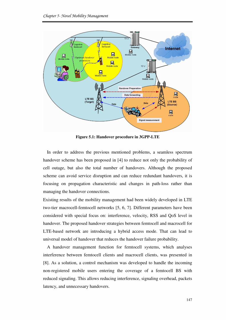
Chapter 5- Novel Mobility Management
147
Figure 5.1: Handover procedure in 3GPP-LTE
In order to address the previous mentioned problems, a seamless spectrum
handover scheme has been proposed in [4] to reduce not only the probability of
cell outage, but also the total number of handovers. Although the proposed
scheme can avoid service disruption and can reduce redundant handovers, it is
focusing on propagation characteristic and changes in path-loss rather than
managing the handover connections.
Existing results of the mobility management had been widely developed in LTE
two-tier macrocell-femtocell networks [5, 6, 7]. Different parameters have been
considered with special focus on: interference, velocity, RSS and QoS level in
handover. The proposed handover strategies between femtocell and macrocell for
LTE-based network are introducing a hybrid access mode. That can lead to
universal model of handover that reduces the handover failure probability.
A handover management function for femtocell systems, which analyses
interference between femtocell clients and macrocell clients, was presented in
[8]. As a solution, a control mechanism was developed to handle the incoming
non-registered mobile users entering the coverage of a femtocell BS with
reduced signaling. This allows reducing interference, signaling overhead, packets
latency, and unnecessary handovers.
Chapter 5- Novel Mobility Management
148
In [9], handover between macrocell and femtocell are evaluated for LTE based
networks. In this work, the authors modified the signaling procedure of handover
at the femtocell gateway while they’re proposed handover algorithm is based on
the UE’s speed. Improved QoS has been achieved due to the reduction of
unnecessary handovers and the predication of any future handovers. On the other
hand, self-configuration and self-optimisation techniques in LTE networks have
been approached in [1]. The proposed evaluations show that a higher
performance can be achieved with distributed mobility load balancing approach
that reduce the handover interruption for LTE networks.
In this chapter, a new handover mechanism is presented based on the decision
made by the entity named CAC function in order to save spectrum resources for
LTE macrocell access. The CAC identifies the thresholds to make the optimal
decision about handover towards target BS. This chapter proposes also the
handover signaling flow schemes as well as the decision rules for the CAC
model. The mobility management considers the speed of the mobile users as the
criterion for handover actions. Markov chain model is used to predict the
probability of user’s data arrival in order to analyse the system performance as a
function for different services and downloading demands. This strategy is able to
predicate the characteristic of user’s velocity and reduce the handover’s
interruption time during re-connection in order to utilise the available resources
efficiently. This approach is based on the assumption that in the near future
cognitive stations will have the ability to make decisions in a collaborative way.
5.2 Handover procedure
The handover procedure is divided to the following sections, namely: cell
discovery, measurement, handover decision, and handover execution. Handover
is made when an active user in the source cell could be best served in the target
cell.
Admission control, handover, and load control are closely joined resource
management functionalities as is shown in the Figure 5.2. Admission control
with the feedback from the load control functionality decides whether an
incoming call (new or handover call) should be accepted or blocked. Admission
control then informs the load control about the change in load conditions due to

Chapter 5- Novel Mobility Management
149
admission of a new or handover call. If an incoming call cannot be served in the
originating cell, and if an adjacent cell can serve the call, the call is immediately
handed over to the adjacent cell [10].
Figure 5.2: Admission control procedure
5.2.1 Cell Discovery and Measurement
The role of cell discovery and measurement is to identify the need of handover
and this part includes the following steps [11]:
• Neighboring cell discovery: It is a preliminary step to be considered
before carrying out the signal strength measurement. The UE can learn
about its neighbours by scanning different channels or via the
provisioning information from its current BS.
• Signal strength measurement: This method allows a UE to handover
only if the current signal is sufficiently weak (less than threshold) and the
other is the stronger of the two. The effect of the threshold depends on its
relative value as compared to the signal strengths of the two BSs at the
point at which they are equal [12]. The UE should synchronise in
frequency and in time with its neighboring cells before it measures their

Chapter 5- Novel Mobility Management
150
radio link quality. The signal strength is averaged over time so that
fluctuations due to radio propagation can be eliminated. Besides the
measurement taken by the UE, the network itself makes measurements
such as the uplink quality, BER of the received data, etc.
• Reporting of measurement result: After the measurement, the UE sends
measurement results to the network periodically or based on trigger
events.
• Information gathering: Besides the physical link quality related
parameters, in heterogeneous environments, the UE is required to collect
other information such as the terminal capabilities, service experiences
status, context information, etc. to assist the vertical handover decision.
5.3 Mobility Management
Mobility management is very important part of 4G mobile wireless network
architecture. In this framework, an open challenge is to design solutions that can
take full advantage of different mobile IP based technologies to support the
desired mobility of heterogeneous terminals, and at the same time provide the
necessary QoS guarantees. There are additional requirements for performance
and packet-level QoS that should be taken into account when trying to design a
handover management scheme, including [13]:
� Fast Handover, i.e. this ensures that UE can receive data packets at its
new location/channel within a reasonable time interval (at certain time
counter) in order to reduce the packet delay as much as possible. This is
extremely important for real-time services.
� Seamless Handover, i.e. any handover algorithm should minimise the
packet loss rate.
� Routing Efficiency, i.e. the routing path between corresponding access
point and UE should be optimised in order to exclude possible redundant
transfers.

Chapter 5- Novel Mobility Management
151
Therefore, it is critical to analyse the expected free resources in different areas
prior to any domain-based mobility management actions. This helps to decide
what happens to a mobile host moving within one domain or between different
domains. This future analysis for spectrum usage is known as the spectrum
forecasting.
5.3.1 Handover Management Operations
Handover management refers to the control functionality of a UE access point
in network in order to maintain a connection with the moving mobile during
active data transmission. The structure of operations of handover management is
shown in Figure 5.3 and includes [14]:
Figure 5.3: Handover of management operations
� Handover Triggering, the handover process is introduced due to some
conditions that may include signal strength, overload, bandwidth
insufficiency, a new better connection becoming available, flow stream
characteristics, change in network topology, etc. Triggering may even
happen according to a user's explicit control or investigational advice
from local monitor software.
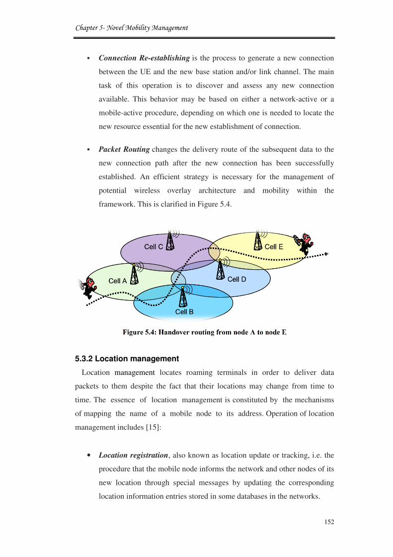
Chapter 5- Novel Mobility Management
152
� Connection Re-establishing is the process to generate a new connection
between the UE and the new base station and/or link channel. The main
task of this operation is to discover and assess any new connection
available. This behavior may be based on either a network-active or a
mobile-active procedure, depending on which one is needed to locate the
new resource essential for the new establishment of connection.
� Packet Routing changes the delivery route of the subsequent data to the
new connection path after the new connection has been successfully
established. An efficient strategy is necessary for the management of
potential wireless overlay architecture and mobility within the
framework. This is clarified in Figure 5.4.
Figure 5.4: Handover routing from node A to node E
5.3.2 Location management
Location management locates roaming terminals in order to deliver data
packets to them despite the fact that their locations may change from time to
time. The essence of location management is constituted by the mechanisms
of mapping the name of a mobile node to its address. Operation of location
management includes [15]:
• Location registration, also known as location update or tracking, i.e. the
procedure that the mobile node informs the network and other nodes of its
new location through special messages by updating the corresponding
location information entries stored in some databases in the networks.

Chapter 5- Novel Mobility Management
153
• Location calling, also known as locating or searching. In most cases
location information stored in databases is only the approximate position
of a mobile device. Location calling is the procedure that, when
calls/packets need to be delivered to the target mobile device, the
network tries to find the mobile device’s exact locality.
5.3.3 Mobile IPv6 Network Layer Performance
Handover management is responsible for maintaining the active sessions of the
Mobile Host (MH) as the mobile moves across the coverage area of various BSs.
Here, the handovers that are considered are those resulting due to the change in
the network layer (IP) connectivity of the host. However, this is not always the
case since a change in link-layer connectivity does not necessarily result in an IP
handover. A handover control protocol should ensure that handovers are fast and
smooth. Therefore, they should be performed without significant delays and
without loss of packets. A requirement that is also dependent on the provided
service [16].
Mobile Internet Protocol Version 6 (MIPv6) improves multiple aspects of MIP,
such as inherent mobility, security and route optimisation, but also preserves its
most important disadvantage, having Home Agent (HA) as a single point of
failure. Moreover, the required update messages used in MIPv6 can prove to be
an additional overhead in case of the increased Mobile Node (MN’s) mobility
since this often results in changes of the Access Network (AN) [17]. Mobile IP
introduces three new functional entities:
• Mobile Node. A host or router that changes its point of attachment from one
network or sub-network to another. A mobile node may change its location
without changing its IP address; it may continue to communicate with other
Internet nodes at any location using its (constant) IP address, assuming link
layer connectivity to a point of attachment is available.
• Home Agent. A router on a mobile node’s home network that tunnels
datagrams for delivery to the mobile node when it is away from home, and
maintains current location information for the mobile node.

Chapter 5- Novel Mobility Management
154
• Foreign Agent. A router on a mobile node’s visited network that provides
routing services to the mobile node while registered. The foreign agent
tunnels and delivers datagrams to the mobile node that were tunneled by the
mobile node’s home agent. For datagrams sent by a mobile node, the foreign
agent may serve as a default router for registered mobile nodes.
Figure 5.5: Mobile IPv6 architecture and operations
The functionality of the MIPv6 is presented in Figure 5.5. Again, no mobility
support is needed as long as the MN stays in the HN (1). Once the MN moves
out from the Home Network (HN) to a Foreign Network (FN) (2), it can obtain
its Care-of Address (CoA) refers to a “second IP address” via either state full like
DHCP for IPv6 (DHCPv6) or stateless address auto-configuration procedure.
Newly obtained CoA must be registered at HA (3) and Correspondent Node CN
(4). The correspondent node is connected to the Internet” using binding update
Chapter 5- Novel Mobility Management
155
messages. Both HA and CN must maintain the list of the current MN’s bonds. As
soon as the MN’s bonds are updated, the packets can be routed directly from the
CN to the MN’s CoA and similarly in the opposite direction, so that the
triangular routing is avoided (5). In the case where the communication between
CN and MN is established, when the latter is already in the FN, the first packets
from the CN are tunneled via the HA to the CoA, like in MIP, until the binding
update process is completed.
Fast Mobility (FMIPv6) attempts to make the handovers proactive if it is
possible to obtain information about the candidates for the new access router
from the co-operating access routers before disconnecting from the old access
router. More recently, network-based IP mobility solutions where the terminal is
not directly involved in managing IP mobility (e.g., Proxy MIPv6 (PMIPv6) are
also being introduced in wireless networks [13].
To reduce the signaling and speed up the handover for movements within the
same Administrative Domain (AD), the MIPv6 local mobility scheme has been
used in the proposed system network.
5.4 Mobility Management in LTE Zones
The future cognitive LTE-femtocell network is to be deployed in coexistence
with the other primary networks. Therefore, the positions of the femtocell BSs
are decided by many factors such as the transmission power, coverage range,
used channels, and number of expected end-users, in order to avoid interfering
with primary networks. It is supposed that not all femtocells would have the
accessibility to landline connections as the LTE BSs. The main reasons for
having fibre connections to the LTE BSs are [18]:
• The LTE BSs are the main providers for services in the cell and they
are connected to the backbone fibre networks and not fibre terminal
edges or DSL connection. This provides the LTE stations with the
highest speed for data transfers using the fibre network.
• The fibre connections are not as replacement for the wireless links
between cognitive BSs. Fibre is used to support the network as an
alternative for wireless links only when there is no way to formulate an

Chapter 5- Novel Mobility Management
156
efficient and reliable wireless link.
• The cost of using fiber in cognitive network especially LTE base
stations should be taken into consideration when choosing the
installation positions and the numbers of femtocell BSs.
The best strategy for installing the cognitive BSs is to place them within the
known boundaries of the primary bases stations. This is to simplify the spectrum
trading between the primary and cognitive networks and also to make it easier in
dealing with temporary licenses issued from local spectrum entities. Thus, a new
network system of multi-access cognitive networks emerges to improve the
cognitive communications performance and reliability. Figure 5.6 shows a big
sized cognitive LTE-femtocell network with variable numbers of deployed
femtocells.
Figure 5.6: Multi-access networks of femtocell and LTE base stations
The LTE cells will allow neighboring cognitive femtocells to use fibre
connections for data exchanges in severe wireless situations. This is likely to
happen whenever a cognitive BS fails to establish a link with remote sites of the
network [19, 20]. These groups of LTE and femtocell BSs share the same
Chapter 5- Novel Mobility Management
157
spectrum band and the network is divided into different zones of services. In
each zone, LTE acts as the master for all other cognitive femtocells. This
division makes it easier to achieve local resources sharing between each zone
femtocells while LTE cell as a main backbone of communication networks. The
spectrum channels are shared in a distributed way between the zone cells. The
LTE exchanges data, information, and transmission requests with other zone sites
using its landline connection and via the other sites LTE cells. The new network
architecture can be defined as a new hybrid system for dynamic spectrum access
using local, central-to-local, and global network resources management. The
challenges of such multi-zoned setup in future cognitive networks can be
summarised as:
• New handover models that allow femtocells located at the edge of LTE
cells to migrate to a neighbour cell. In this way, the handover is
happening to the femtocell with all its end-users in operation. This
creates a new emerging model of dealing with one set of users who will
need to be connected to another spectrum band while maintaining
online transmissions. The main goal is to create a system that can
respond and act to unpredicted wireless spectral changes and various
numbers of users.
• Novel cognitive femtocells handover that is able to monitor the
spectrum usage and make decisions to re-connect to another cell when
there are more transmission opportunities become available. This
should reduce the traffic loads and improve the accessibility to the free
spectrum in local areas.
• More independent BSs those are able to reconfigure and adapt to
various wireless spectral situations and network interfacing
managements. This requires extended cognition engine designs for the
cognitive Base Stations and new protocols for transferring knowledge
between different network stations as in [21].
Chapter 5- Novel Mobility Management
158
• Establishing temporal, local, flexible zones of neighboured femtocells.
These formulations may ease the access procedure and mobility
managements in smaller areas of one pool of spectrum channels.
• Reducing the complexity of dealing with main spectrum entities by
establishing local governing units supported by protocols. The
cooperation between various cells is necessary for the success of the
proposed models.
The following section will investigate the criterion for the formulation of these
zones, changes in the zones’ sizes and boundaries, and one possible scenario for
cognitive femtocell migration between these zones.
5.5 Femtocell Migration between LTE Zones
The zoned cell groups are proposed to be dynamically changeable formulations
to hosts and release new cognitive femtocells. In other words, cognitive
femtocells may join or leave LTE zones at any time as their wireless spectral
situation change. These changes in wireless network may result from the
dynamic activities of the primary users. Such changes may affect local wireless
setting at certain femtocells and make it difficult to connect to other femtocells
inside a definite zone. Consequently, a femtocell may decide to leave a certain
LTE zone and join another one, according to the negotiations between the
femtocell BS and other neighbored zones. The objectives of this cell migration
are to attain the most efficient spectrum utilisation and the highest quality of
service. The main assumption is that the coexistence between LTE and femtocell
is done in a cooperative way and based on dynamic network management that
can adapt to any real-time adaptation requirements [22].
In order to be able to formulate the proposed zones, there should be
arrangements to share the necessary awareness on the wireless spectral and
resource changes at the cellular and network levels. The best scenario is to
supply information in two levels: global networks and local zone. In the global
networks, information is spread between zones and independent cells, and vice-
versa, to make them aware of the general wireless situation inside each area. As

Chapter 5- Novel Mobility Management
159
well as, each zone to its cells may provide this information. On the other hand, a
local zone (x for example) may provide regulating data, changes inside a zone,
and neighbored zones change to the cells grouped by zone(x). An IP address may
be given to different zones on a temporary basis to simplify the way of providing
services throughout the network. One suggestion is to use the LTE IP address as
the zone address. Therefore, a new and fully dynamic network is created to
various wireless events.
The disengagement process for a femtocell leaving from one zone to another
can be performed through informing its zone. The cell takes the decision to leave
a zone whenever it recognises that spectrum availability has changed and it is not
possible to establish links with other femtocells as before. This can be performed
by setting a linkage threshold for the number of link request iterations before
making the handover decision. This might happen also when the reports received
from local spectrum governing entities show a major change in the forecasted
and presently accessible channels for cognitive communications [18]. However,
it is necessary to set regulations that prevent femtocells from leaving zones just
because they are turning selfish and they want to keep more resources for
themselves. Whenever a femtocell is intending to leave the zone, all other zone
femtocells are informed about this decision. Then all other zone femtocells may
terminate their special Local Zone Connections with the leaving femtocell and
re-direct their transmission routes using other stations. The migrating cell
becomes free and can immediately join any other zone, as shown in Figure 5.7.
Figure 5.7: Femtocell migrations between two LTE zones

Chapter 5- Novel Mobility Management
160
Here, there are two methods for joining the new zone, either the femtocell had
negotiated this with the target LTE zone prior to its decision to leave the home
zone, or it makes this decision after it becomes free. In both cases the femtocell
will be able to attend the new zone only if it had the same wireless spectral and
resources situations and there are no more obligations any more with the old
zone.
Normally, LTE accepts the request issued by an individual femtocell to join its
zone as long as this application follows the above procedures and gets more
resources. The time taken for cell migration should be quick enough to prevent
any interruptions in communications for the migrated femtocell and to prevent
being trapped between two zones of services. At all times, the cell is still part of
a bigger network infrastructure and operator services. This is in case the cell did
not identify itself as an independent service zone. The local communications and
re-directing of the services throughout the zone is changed as soon as the new
femtocell is unified with the service area.
Handover management is a challengeable task when implemented in femtocell
due to the dynamic spectrum access modeling. In addition, due to technological
challenges and system operator requirements, the initial 3GPP specification for
handover in femtocell focused on one direction only that is from FBS to LTE
macrocell. Therefore, three possible handover scenarios are likely to occur in
femtocell networks [23], as depicted in Figure 5.8:
• Hand-in: this scenario presents the handover where an UE switch out
from macrocell BS to FBS.
• Hand-out: represents the handover that is performed from FBS to
macrocell BS.
• Inter-FBS Handover: it corresponds to the scenario of handover from
one FBS to another FBS. In this scenario all FBSs are assumed to be
placed at the same location and served by the same service provider.

Chapter 5- Novel Mobility Management
161
Figure 5.8: Handover scenario in femtocell networks
5.6 Handover Call Flow
This section proposes comprehensive handover signal flows for the small and
medium scale deployable integrated LTE-femtocell network architecture. The
Mobility Management Entity (MME) is the key manage node for LTE macrocell
network. It provides the control plane function for mobility between LTE and
other femtocell networks, and is responsible for choosing the right serving
gateway for an UE and for authenticating them [2]. The serving gateway (SGW)
supports users data and provide routing and forwarding functionality between
LTE or FBS and packet data network. The proposed handover schemes optimise
the selection/reselection management functionalities in the LTE-femtocell
handover procedure. Moreover, the improve handover scheme is considered
sensing mechanism to select the best free channel available.
During the information gathering stage, the UE collects the information about
the handover candidates, and authentications are acquired for security purposes.
In handover chosen stage, the best handover option is calculated. Finally, after
deciding to make handover, the UE initiates handover. The handover procedure
can normally consist of three phases:

Chapter 5- Novel Mobility Management
162
• Handover preparation: this phase where measurements are made and
information about surrounding BSs is prepared from mobile user after
scanning the neighboring cell BS. During the scanning process, the
mobile user measures the channel quality or signal strength of each
neighboring candidate BSs. However, the mobile user sends
measurement report message to serving BS in order to select the best
candidate BS. Accordingly, the mobile users of serving base station and
target base station make preparation before the mobile user connect to
the new cell. Then, handover decision is process when the serving BS
offers the handover decision according to the received measurement
report message from mobile user. The message is send from admission
control to the target BS based on the QoS information. Finally, sending
handover command to the mobile user.
• Handover execution: in this phase the connection is starting to detach
from old cell and synchronise to the new cell and accesses the target
cell. In this stage, the mobile user desires to synchronise with downlink
transmission and obtain downlink and uplink transmission parameters
with target BS through gate-way router.
• Handover completion: this phase includes the processes of handover
confirm and path switch. Therefore, the serving gateway switches is the
route of transport the data to the target BS. Thus, the serving gateway
exchanges massage with MME and release resource base on reception
of the release message, the serving BS can release radio and control of
related resources. After that, target BS can transmit the packet data. The
handover procedure is completed afterward, and the data broadcast
between the mobile and the new serving BS can be started.
5.6.1 Hand-in Procedure
The handover from LTE BS domain into femtocell BS domain is quite
demanding and complex since there are hundreds of possible targets FBSs. In
hand-in procedure, the UE needs to select the most appropriate target FBS. The
interference level should be considered as a basic decision parameter. Whenever
the UE in the LTE network detects a signal from FBS, it sends a measurement

Chapter 5- Novel Mobility Management
163
report to the connected LTE-BS. Based on the measurement report, UE decides
to perform handover, and the LTE-BS starts handover procedures by sending a
handover request to the serving SGW. The handover request is forwarded from
the source LTE BS to target FBS through CN. The CAC is performed only by
FBS to check whether the call can be accepted or not. After that the FBS
responds to the handover request. Then the packet data are forwarded to target
FBS. Now the UE re-establishes a channel with the target FBS and detaches from
the source LTE BS, and also synchronised with the target FBS. The proposed
mobility fictionalisation is important to consider in handover decision to optimise
the handover procedure. The authentication is checked in the preparation phase
of handover, thus LTE to femtocell handover is more complex than existing
handover between LTE macrocells. The signalling flow procedure of the
proposed handover scheme from macrocell to femtocell is shown in Figure 5.9.
5.6.2 Hand-out Procedure
The handover procedure from FBS to LTE BS is relatively simple as compared
with the hand-in scenario because there is only one candidate BS and UE has no
other option to select the target cell. It means that in this scenario, complex target
cell selection mechanism is unnecessary. The UE measures the Received Signal
Strength (RSS), which includes path loss, antenna gain, log-normal shadowing,
and fast fading averaged over all the reference symbols from LTE node, to
determine which is stronger than FBSs-RSS, and the UE will connect directly
without a complex interference calculation and authorisation check as in the
hand-in scenario. After deciding for handover, the FBS starts handover
procedures by sending a handover request to SGW. The CAC of the LTE node
and SGW are to check whether the call should be accepted. Then the LTE
responds to the handover request by starting to setup a new link between SGW
and the target LTE, so that the packet data are forwarded to target LTE. At this
stage, the UE needs to re-establish a channel with the target LTE and detach
from the source femtocell, and also establish synchronisation with the target
LTE. The mobile user starts to send a handover complete message to SGW.
Then, the FBS disconnects the old link with the SGW. The signalling for
femtocell to macrocell handover flows is depicted in Figure 5.10.

Chapter 5- Novel Mobility Management
164
Figure 5.9: Handover from macrocell to femtocell

Chapter 5- Novel Mobility Management
165
Figure 5.10: Handover from femtocell to macrocell

Chapter 5- Novel Mobility Management
166
5.7 System Model
5.7.1 Markov Chain for Handover Decisions
The handover call arriving rate in diverse femtocell environments is hard to
handle because of the frequent and unwanted handovers that causes significant
decrease in the QoS. In LTE-femtocell overlaid networks, blocking a macrocell
to femtocell handover call will not dropping that call. By reserving large amount
of bandwidth for the macrocell to femtocell handover calls, bandwidth utilisation
should not be sacrificed to reduce handover call blocking probability. The
proficient handover scheme to enhance the bandwidth utilisation is performed by
improving the handover call blocking probability using the CAC mechanism.
The queuing system with Poisson input as Markovian process (denoted by M)
is considered in this work. The arrival of LTE-femtocell users’ calls is based on
M/M/1 queuing system. The queuing systems assumes that the number of arrival
of packets (data network) for a given interval of time t follows a Poisson
distribution process with parameter of product of λt, as shown in Figure 5.11.
Figure 5.11: Multi server queues systems
The service time for each server is assumed to be a distributed function with an
exponential distribution of service rate μ. The length of a data packet follows an
arbitrary Probability Density Function (PDF). Due to the fact that the power of a
transmitted signal is much higher than the power of the received signal in
wireless medium, instantaneous collision detection is not possible for wireless
nodes. The Poisson process theory has the ability to split every arrived call that is
randomly routed with probability P to stream 1 and (1-P) to stream 2. Streams 1
and 2 are Poisson of rates Pλ and (1-P) λ respectively. For � arrivals within a
time intervalt, let the probability distribution function P(n) is given as [24]:

Chapter 5- Novel Mobility Management
167
P(n) = (λt)�
n e���(5.1)
where λ denotes the arrival rate of customers in system, and n is presented
number of servers. This assumption is a very good approximation for arrival
process in real systems and we denote: λ��, λ��and µ to represent the average
rate of handover call from macrocell to femtocell, the average originating new
calls rate at femtocell area, and service rate respectively [24]. A system with the
value of K less than N implies that the system gives more priority to macrocell-
femtocell handover calls than the originating new calls at femtocell area, as
shown in Figure 5.12.
Figure 5.12: Markov chain model of LTE-femtocell handover scheme
The fixed value of K for all femtocell environments reduces the resource
utilisation. Several schemes or techniques may be adopted to fix the value of K.
For femtocell coverage area with a lower probability of handover call rate, then
can use very close values of K and N. The system can also use a variable value of
K to optimise both resource management and handover call blocking probability.
Thus, the total arrival rate of the connection request of the system λ�is [25]:
λ� = �λ�� + λ��for0 ≤ j < !(5.2)λ��forK ≤ j < �
The blocking probability of the calls originating at femtocell area is

Chapter 5- Novel Mobility Management
168
P$ =%(� + �)&.�'�&
i! μ'*
'+&P(0)(5.3)
Figure 5.13: Markov model

Chapter 5- Novel Mobility Management
169
Where N is the number of customers in the system, and K is the system total
capacity or number of waiting customers. The mobility of each node is modeled
by Markov chain on the quantised space derived from the above partition. The
performance of this method has also been analysed using Markov model, as
shown in the Figure 5.13.
This block diagram represents our OPNET developed project to interconnect
Markov Chain to the LTE/femto system. Markov Chain is already included in
OPNET functions to allow enabling QoS evaluations. This function is
incorporated with the proposed scenarios of CAC to analyse handover models
performance using data arrival predication.
The number of handovers that occurred in a particular state of the cognitive
networks multiplied with the steady state probability of that state will give the
handover probability of that particular state. Thus, handover probability of the
networks is obtained by assuming the handover probabilities of all the states of
the hierarchical networks. Hence, the probability of handover occurred in
LTE/femtocell networks can be calculated as follows:
Probability23 =%N23 ∗ π. N67889(S)∀<
(5.4)
Where S is the probability of being in a state, as the Markov chain is irreducible,
N23represents the total number of LTE/femto handovers that occurred at
specific state. N67889denotes the number of services residing at a certain
femtocell/LTE domain. Thus, observing the outgoing and incoming transitions
for a given state ‘S’ and the steady state probability allow to evaluate the network
performance for that change.
5.7.2 Novel Mechanism for Call Admission Control
In this section, a new CAC mechanism is proposed to monitor the necessary
measured parameters on the cell and control the admission of incoming
connections. The work is driven by a novel scenario where two groups travel
across each other at specific speeds and the corresponding network spectrum
availability changes frequently since each group has full access to spectrum
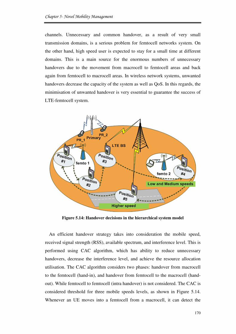
Chapter 5- Novel Mobility Management
170
channels. Unnecessary and common handover, as a result of very small
transmission domains, is a serious problem for femtocell networks system. On
the other hand, high speed user is expected to stay for a small time at different
domains. This is a main source for the enormous numbers of unnecessary
handovers due to the movement from macrocell to femtocell areas and back
again from femtocell to macrocell areas. In wireless network systems, unwanted
handovers decrease the capacity of the system as well as QoS. In this regards, the
minimisation of unwanted handover is very essential to guarantee the success of
LTE-femtocell system.
Figure 5.14: Handover decisions in the hierarchical system model
An efficient handover strategy takes into consideration the mobile speed,
received signal strength (RSS), available spectrum, and interference level. This is
performed using CAC algorithm, which has ability to reduce unnecessary
handovers, decrease the interference level, and achieve the resource allocation
utilisation. The CAC algorithm considers two phases: handover from macrocell
to the femtocell (hand-in), and handover from femtocell to the macrocell (hand-
out). While femtocell to femtocell (intra handover) is not considered. The CAC is
considered threshold for three mobile speeds levels, as shown in Figure 5.14.
Whenever an UE moves into a femtocell from a macrocell, it can detect the

Chapter 5- Novel Mobility Management
171
existence of an FBS and decide to switch into the femtocell network. In contrast,
whenever a FBS user moves away from the femtocell BS, it issues a handover
request whenever it detects that the strength from FBS is weaker than the
strength from macrocell BS. Later, if the handover is approved by the macrocell
BS, the mobile connection with the femtocell will be terminated and
communications will be switched to the macrocell network.
The mechanism of the CAC is illustrated as follows: whenever a cognitive
femtocell receives a handover request from the access service network gateways
or from the UE, the femtocell makes a decision to allow the handover to take
place according to the proposed CAC algorithm shown in Figure 5.15.
Since users with high velocity may pass through multiple FBS zones, it may
not be possible to maintain a constant QoS over UE connection. Thus, the
number of detected handovers (H) in a femtocell coverage area is a function of
femtocell radius (r), speed (S) of the UE, and angle of movement (θ) with respect
to the direction of FBS. The number of handovers can be expressed as:
> = ?(@, A, B)(5.5)
The decision of handover from LTE and FBS can be expression:
>CDEFGHIJ =RSS�L��M. SNO. SIR�L��M(5.6)
Where RAASETUIdenotes to the Received Signal Strength Indicator (RSSI) from
FBS, AVW denotes to the velocity of UE, and AXRSETUI denotes to the signal-to-
interference at femtocell area. The value of RAASETUIis 1 only if the received
signal level does not go below a threshold level for a specific time interval, else it
is 0. AVW represents 1 if the velocity of UE is less than a threshold velocity,
otherwise 0. The value of AXRSETUI is 1 either if the SIR at femtocell
environment is greater than the threshold value or greater than SIR at macrocell
environment; else its value is 0. Thus the value of decision parameter is either 0
or 1.

Chapter 5- Novel Mobility Management
172
Figure 5.15: New CAC mechanism for handover call authentication

Chapter 5- Novel Mobility Management
173
An admission for macrocell to femtocell handover is only accepted by FBS if
the value of >CDEFGHIJ is 1. The threshold level of the signal is the minimum
level of the signal that is required to handover a UE from LTE BS to femtocell
BS. Sometimes UE receives a signal that is greater than minimum request level
but during very short time the level goes down again due to the movement of the
UE. Whenever a UE moves to femtocell BS coverage area, the UE must keep
threshold level of the signal at the minimum threshold handover. A call can be
accepted if, either SIR level in the target femtocell is higher than the threshold
level or less than the SIR level of current macrocell area. Once, any of these
conditions satisfied then the available channel is taken into calculation.
Otherwise, the allocation of LTE-femtocell user is checked against any drop in
their signal quality before handover may occur.
The handover threshold may be adjusted according to the service type, QoS
requirement, and the velocity of the user, except for the mobile traffic required
real time services [26]. Otherwise, packets can be buffered until handover
performed and a channel becomes available. The thresholds for the CAC scheme
can be then identified in terms of speed as: Low (Low mobile speed state: from 0
to 15km/h; slow walk, stationary), Medium (Medium mobile speed state: from
15 to 30km/h; speed equivalent to that of riding a bicycle), or High (High mobile
speed state: anything above 30km/h, drive a car).
5.8 Cognitive Node Implementation in OPNET
In OPNET, a network is made up of individual nodes, and a node is made up
of modules. The hierarchy of packet flows through the different modules in the
node has been modeled using different layers in the networking system. These
modules are composed of process models that define the module’s behavior and
contain the C++ code functions of the program. The original IP process model of
the node selected for femtocell performance evaluation in OPNET modeler is
shown in Figure 5.16. The figure shows the different layers and port connections
at the module level that performs the most basic general functions.
The node model in Figure 5.17 shows the modification model with a new
module for handover management named as Call_Admission_Control. The
modification was implemented by modified the IP layer system unit and

Chapter 5- Novel Mobility Management
174
incorporating the new handover technique with the call admission control.
Figure 5.16: Node Process Model in OPNET17.1
Figure 5.17: Node modification by adding admission control process
Figure 5.18 illustrates the process model level of the CAC module proposed in
Figure 5.17. Once a handover request arrived to the FBS, the call scheme is

Chapter 5- Novel Mobility Management
175
invoked to decide to accept or reject the mobile phone registration. Initially, the
activation of the process starts at the “open” state that initialises state variables
and other interrupts. Packets are then forwarded to the “call_admission” process
state that evaluates the eligibility of the mobile user to perform handover. This is
decided by comparing the mobile speed to the thresholds setting. If the mobile
speed is higher than the assigned limits for performing handover, the handover
request will be declined and the call will be aborted and the process will be
terminated and moved to “end” state.
Figure 5.18: Call admission control “process model”
Otherwise, handover request will be approved and the call will be accepted and
forwarded to the “connect” process state to start connection. If the connection
failed to be maintained then the call will be terminated as soon as the interrupt
“ABORT || CLOSE” is enabled and the process will be ended with “end” process
state. If the connection is successful, the interrupt for data transfer will be
enabled as “START_DATA_XFER” interrupt activated. Next, the “Idle” state will
be activated to check if the video incoming packet from the “send” process state
has the suitable framing size that matches the available transmission opportunity.
As soon as the transmission completed, the “idle” activates the
“SEND_CLOSE” interrupt to close the send process with “send close” process

Chapter 5- Novel Mobility Management
176
state. Similarly, the “idle” state is also responsible to check the incoming packets
from the mobile user using the “receive” state and
“RECEIVE_VIDEO_FRAME” interrupt. Once this completed, the “idle” state
will close the connection using the “CLOSE” interrupt and “end” process state.
The “idle” state has also another interrupt named as “default” that allow to add
longer route to incoming packets while the “idle” is busy with certain process.
This allows the “idle” state to handle one action at a time to prevent collision of
services. The mobile speed is obtained by the pipeline code shown in algorithm
5.1.
Algorithm 5.1. C++ Code for Mobile Speed Calculating
1:
2:
3:
4:
5:
6:
7:
8:
9:
10:
11:
12:
13:
14:
15:
16:
17:
18:
19:
20:
21:
dra_propdel_mt (OP_SIM_CONTEXT_ARG_OPT_COMMA Packet *
pkptr)
{
double start_prop_delay, end_prop_delay;
double start_prop_distance, end_prop_distance;
double start_prop_VELOCITY, start_prop_velocity;
/** Compute the propagation delay separating the **/
/** radio transmitter from the radio receiver.**/
FIN_MT (dra_propdel (pkptr));
/* Get the start distance between transmitter and receiver. */
start_prop_distance = op_td_get_dbl (pkptr,
OPC_TDA_RA_START_DIST);
/* Get the end distance between transmitter and receiver. */
end_prop_distance = op_td_get_dbl (pkptr,
OPC_TDA_RA_END_DIST);
/* Compute mobile speed to start of reception. */
start_prop_velocity = start_prop_distance / start_prop_delay;
/* Compute mobile speed to end of reception. */
end_prop_velocity = end_prop_distance / end_prop_delay;
/* Place both mobile speeds in packet transmission data attributes. */
op_td_set_dbl (pkptr, OPC_TDA_RA_START_PROPDEL,
start_prop_velocity);
op_td_set_dbl (pkptr, OPC_TDA_RA_END_PROPDEL,

Chapter 5- Novel Mobility Management
177
22:
end_prop_velocity);
FOUT }
In this code, the mobile speed is calculated by defining the distance and the
time of transmission of the mobile to the femtocell base station. The calculated
mobile ground speed “end_prop_velocity” is attached to the attributes of the
transmitted packets. This is processed by the “call_admission” state in order to
decide upon accepting handover requests.
5.9 System Configuration
In this section, the simulation and results of system evaluations are presented
in order to reinforce the advantages of the proposed CAC scheme using the
Markov model. The performance of the new proposed system is evaluated and
results obtained from several different scenarios are discussed.
Performance of the proposed system is compared with the traditional scheme to
approve the validation of the proposed CAC solution. The traditional solution
employs an advanced admission control model that uses the default processing
for handover requests at low and medium speeds [27, 28]. The following case
studies describe the handover scenarios implemented in the OPNET17.1
modular. The aim of these five case studies is to evaluate the different
approaches and technologies that can be used to reduce the numbers of
handovers for mobile phones travelling between LTE and Femtocell transmission
domains. The simulation parameters setting are presented in Table 5.1.
Table 5.1 Simulation parameters for handover project
Parameters Value Parameters Value
LTE transmit power 40dBm
Femto transmit power 20dBm
Number of LTE 5
Number of femtocell 5
Number of UE 2
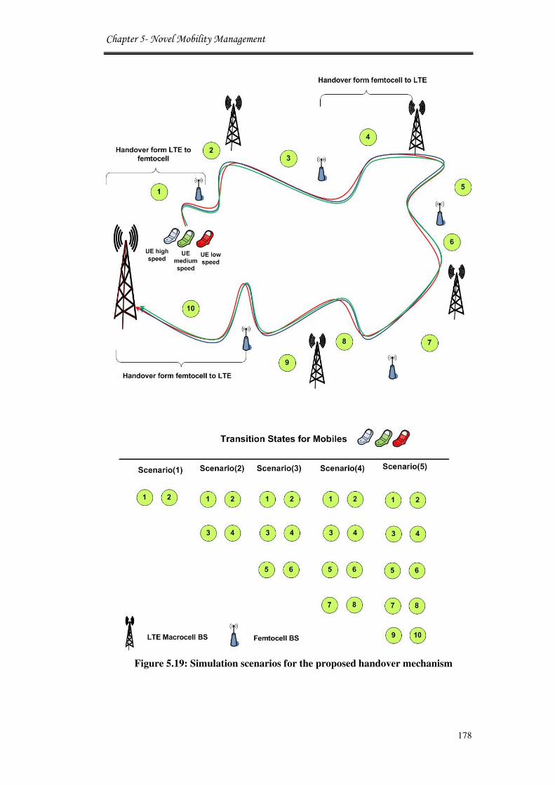
Chapter 5- Novel Mobility Management
178
Figure 5.19: Simulation scenarios for the proposed handover mechanism

Chapter 5- Novel Mobility Management
179
Mobile users handover request are set to arrive according to Poisson process.
The angle of UE movement is generated randomly and the position is used to
update the UE speed according to algorithm 5.1. The connection time of a UE in
the femtocell domain is calculated from the velocity and the movement direction.
Five scenarios were designed to examine the performance of a UE moves
between LTE and femtocell domains each 120 seconds. Figure 5.19 shows the
network topology of different scenarios that are used to validate the system
handover mechanism. The network topology contains five LTE BS and five
femtocell BSs and one mobile user. The user is moving at two different speeds of
Low 5Km/h and Medium 20Km/h. The user will all follow the same trajectory of
movement between the various LTE and femtocell domains at different speeds.
In order to evaluate the proposed CAC mode, five scenarios were developed to
allow specific numbers of handovers. In each scenario, the case study involves
four mobile speed comparisons: two for the proposed CAC model and the other
two using the traditional handover scheme. These case studies show the
performance of the system using the two speeds of low and medium as discussed
earlier. The OPNET project model for scenario one is shown in Figure 5.20.
Figure 5.20: Scenario (1) for handover LTE-femtocell in OPNET17.1

Chapter 5- Novel Mobility Management
180
5.9.1 Simulation Results
Simulations were conducted to validate the proposed handover scheme against
the default traditional handover model.
Retransmission attempts are a traditional mechanism for detecting the
congestion in the network; it can be compared to the packet loss indicator. The
simulation results of the retransmission rate are given in Figure 5.21 in pkts/sec.
The figure shows the number of handovers from macrocell to femtocell and
femtocell to macrocell for the different scenarios. The proposed scheme shows a
significant reduction in the numbers of re-transmitted packets as a function for
the numbers of occurred handovers. This proves that the proposed CAC has
eliminated many unnecessary handovers subject to the assigned threshold for
speed determination.
The best results were obtained with the low mobile speed that is connected to
base stations equipped with the proposed CAC than the medium speed. While
higher numbers of packets available to retransmit are observed with the
traditional scheme as there are too many packets to retransmit.
Figure 5.21: Retransmission rate vs number of handover
Figure 5.22 shows the handover latency/delay curves for successful handovers
of the five simulated scenarios and two call admission case studies. The
1 2 3 4 5 6 7 8 9 10 110.1
0.15
0.2
0.25
0.3
0.35
0.4
Retr
an
sm
iss
ion
Ra
te (
pkts
/se
c)
Number of Handovers
Scenario(1)
Scenario(2)
Scenario(3)
Scenario(4)
Scenario(5)
Proposed CAC with low speed mobile userProposed CAC with low speed mobile user
Proposed CAC with medium speed mobile userProposed CAC with medium speed mobile user
Traditional CAC with low speed mobile userTraditional CAC with low speed mobile user
Traditional CAC with medium speed mobile userTraditional CAC with medium speed mobile user

Chapter 5- Novel Mobility Management
181
handover latency is the time consumed from the instant when the handover
decision is made by the target BS to the instant when the UE terminates
connection with its serving BS to launch the handover process.
This simulation part study the handover latency comparison of the different
scenarios and combinations of them provides the basis for seamless handover
within the LTE-femtocell network. The advantage for the implementation of the
proposed mobility management scheme in the project’s field trial is to speed up
the handover latency and provide uninterrupted services for roaming users. Now,
taking the figure into account that depicts the results of the handover latency
scenarios, the proposed CAC with low mobile speed that has been taken the
lowest part of the retransmission rate overhead, now is accomplished in advance
when mobile user initially connects to the BS. This means that proposed CAC
implementation features decrease the handover overall awaiting delay for a
network with heterogonous design of BSs. Summarising the entire procedure
shows that the proposed scheme depicts the best performances compared to
traditional handover schemes.
Figure 5.22: Latency of successful handovers
Figure 5.23 shows the throughput graphs for all the simulated scenarios as a
function of the connection time. The figure depicts that there is a considerable
1 2 3 4 5 6 7 8 9 10 110.01
0.02
0.03
0.04
0.05
0.06
Han
do
ve
r L
ate
nc
y (
sec
)
Number of Handovers
Scenario(1)
Scenario(2)
Scenario(3)
Scenario(4)
Scenario(5)
Traditional CAC with low speed mobile userTraditional CAC with low speed mobile user
Proposed CAC with low speed mobile userProposed CAC with low speed mobile user
Proposed CAC with medium speed mobile userProposed CAC with medium speed mobile user
Traditional CAC with medium speed mobile userTraditional CAC with medium speed mobile user

Chapter 5- Novel Mobility Management
182
increase in the throughput with the new scheme of CAC with the highest values
with the low speed, followed by the medium speed. The traditional scheme
results come at the late with the lowest throughput values. This proves that the
new CAC scheme performs handovers with shorter time processing enabling the
mobile user to start transmission earlier and then exchange more data compared
to the traditional handover models. The same performance can be seen for
different scenarios that employ the same network architecture with different
numbers of handovers at longer trajectories.
Figure 5.23: Throughput graphs for simulated scenarios
The main intension for introducing the new CAC scheme is to allow efficient
resource allocation in a heterogeneous network that is composed of various
numbers of LTE and femtocell BSs. The previous simulation results have proved
the novelty of the given solution at the femtocell level. In order to investigate the
given solution performance at the LTE level, the allocation of connection to the
mobile user is studied to show the difference between various mobile speeds
alterations. In this field, the LTE dedicated bearers carry traffic for IP flows that
have been identified to require a specific packet forwarding treatment. Such
dedicated bearer can be either GBR (Guaranteed Bit Rate) or non-GBR, where
non-GBR bearers can suffer packet loss under congestion while GBR bearers are
0 120 240 360 480 600
50000
100000
150000
200000
250000
300000
350000
400000
450000
500000
Th
rou
gh
pu
t (b
its
/sec)
Connection Time (Sec)
Proposed CAC with low speed mobile userProposed CAC with low speed mobile user
Traditional CAC with low speed mobile userTraditional CAC with low speed mobile user
Proposed CAC with medium speed mobile userProposed CAC with medium speed mobile user
Traditional CAC with medium speed mobile userTraditional CAC with medium speed mobile user
Scenario (1) Scenario (2) Scenario (3) Scenario (4) Scenario (5)

Chapter 5- Novel Mobility Management
183
immune to such losses. These bearers are normally subject to admission control
within the network. Therefore, the highest numbers of the admitted GBR can
show clearly the time where a certain user application is the most connected to
the LTE BS. This is shown in Figure 5.24 that shows the total number of
admitted Guaranteed Bit Rate (GBR) bearers with the connection time. The
figure shows that a mobile user with high speed has the highest GBR values
followed by the mobile users with medium and low speeds respectively. This is
due to the fact that the mobile users with low and medium speeds are connected
to the femtocell BSs for the most of the time of the simulation in contrast to the
high speed user that is always declined admission to femtocells connections and
had to remain connected to the LTE BSs.
Figure 5.24: Total number of admitted GBR bearers with access time
In summary, the simulation results show clearly that the effectiveness of the
proposed CAC algorithm for handover management increases the system
performance significantly. That is achievable by reducing unnecessary handover
in femtocell cognitive networks that is help to manage the network resources
efficiently between femtocells and macrocells BSs. The comparison with the
traditional scheme shows that the algorithm proposed in this chapter have a better
0 120 240 360 480 6001
2
3
4
5
6
7
8
9
ConnectionTime (Sec)
A
dm
issio
n C
on
tro
l
To
tal N
um
ber
of
Ad
mit
ted
GB
R b
eare
rs
Low speed mobile user with LTE/femto connectionLow speed mobile user with LTE/femto connection
High Speed Mobile User with LTE connectionHigh Speed Mobile User with LTE connection
Medium speed mobile user with LTE/femto connectionMedium speed mobile user with LTE/femto connection
Scenario (1) Scenario (2) Scenario (3) Scenario (4) Scenario (5)

Chapter 5- Novel Mobility Management
184
performance in the rate of unnecessary handovers and the average number of
handovers, especially in Medium and low mobile speed, for a small penalty of
signaling overhead.
5.10 Conclusion
This chapter presents a novel handover management scheme for cognitive
networks that employ two-tiers of LTE and femtocell BSs. The proposed
handover selection mechanism allows femtocells to choose to connect to low and
medium mobile speeds in order to attain better resource management. This is due
to the fact that high speed mobile users stay only for short time within femtocell
small range domains. In this way, new algorithms were developed at the network
layer to set the thresholds for either admit/reject handovers requests from mobile
users with different speeds. A new modification has been developed to allow
calculating the ground speed of mobile users and attach it to the packets
attributes to enable the functioning of the proposed CAC. The performance of the
proposed scheme has been evaluated and the results show major improvements
in the system performance for the LTE-femtocell network compared to the
traditional handover schemes. The proposed model for handover is a promising
solution for applications that employ cognitive femtocell as part of their
architecture in future open access networks.
5.11 References
[1] S. Al-Rubaye, A. Al-Dulaimi, and J. Cosmas, Spectrum Handover Strategies
for Cognitive Femtocell Networks, In Femtocell Communications and
Technologies: Business Opportunities and Deployment Challenges, Edited
by R. Saeed, B. Chaudhari, Rania Mokhtar, IGI Global, July 2012.
[2] A. Ulvan, R. Bestak, and M. Ulvan, “The study of handover procedure in
LTE-based femtocell network,” In Proc. of the IEEE 3rd
Joint IFIP
Wireless and Mobile Networking Conf. (WMNC), Budapest, Hungary,
2010, pp. 1 - 6.
[3] H. Zhang, X. Wen, B. Wang, W. Zheng, and Y. Sun, “Novel Handover
Mechanism between Femtocell and Macrocell for LTE based Networks,”

Chapter 5- Novel Mobility Management
185
In Proc. of the 2nd
International Conference on Communication Software
and Networks, Singapore, 2010.
[4] O. Jo and D. Cho, “Seamless Spectrum Handover Considering Differential
Path-loss in Cognitive Radio Systems,” IEEE Communications Letters, vol.
13, no. 3, pp. 190 - 192, March 2009.
[5] J. M. Moon, and D. H. Cho, “Novel Handover Decision Algorithm in
Hierarchical Macro/Femtocell Networks,” In Proc. of the IEEE Wireless
Communications and Networking Conference (WCNC 2010), Sydney,
Australia, 2010, pp. 1 - 6.
[6] S. Wu, “A New Handover Strategy between Femtocell and Macrocell for
LTE-based Network,” In Proc. of the IEEE 4th
International Conference on
Ubi-Media Computing, Sao Paulo, Brazil, 2011.
[7] S. Alagu and T. Meyyappan, “Analysis of Handoff Schemes in Wireless
Mobile Network,” IJCES International Journal of Computer Engineering
Science, vol. 1, no. 2, pp. 1 - 12, 2011.
[8] Z. Fan and Y. Sun, “Access and handover management for femtocell
systems.” In Proc. of the IEEE 71th
Vehicular Technology Conference,
Taipei, Taiwan, 2010.
[9] J. Zhang, X. Zheng, and Y. Yang, “Self-Configuration and Self-Optimization
for LTE Networks,” IEEE Communications Magazine, vol. 48, no. 2, pp.
94 - 100, February 2010.
[10] B. Eklundh, “Channel Utilization and Blocking Probability in a Cellular
Mobile Telephone System with Directed Retry,” IEEE Transactions on
Communications, vol. 34, no. 4, pp. 329 - 337, 1986.
[11] Q. Nguyen-Vuong, “Mobility Management in 4G Wireless Heterogeneous
Networks,” PhD thesis, Department of Computer Science and Networks,
University D’evry Val-D’essonne, 2008.
[12] I. Stojmenovic, Handbook of wireless Networks and Mobile Computing,
ISBN 0-471-41902-8, John Wiley & Sons Inc., 2002.
[13] L. Budzisz, “Stream Control Transmission Protocol (SCTP), a proposal for
seamless handover management at the transport layer in heterogeneous
wireless networks,” PhD thesis, Department of Signal Theory and
Communication, Universitat Polit`ecnica de Catalunya, 2009.

Chapter 5- Novel Mobility Management
186
[14] J. Sun and J. Sauvola, “Mobility and Mobility Management: A Conceptual
Framework”, In Proc. of the IEEE 10th
International Conference on
Network (ICON), Grand Cop Thorne Waterfront, Singapore, August 2002.
[15] F. Zarai, “Quality of Service and Security in Wireless Fourth Generation
Networks,” CNAS Technical Report, The Communication Network and
Security (CN&S) research Laboratory, Tunisia, January 2008.
[16] L. Dimopoulou, G. Leoleis, and I. Venieris, “Fast Handover Support in a
WLAN Environment: Challenges and Perspectives,” IEEE Networks, vol.
19, no. 3, pp. 14 - 20, May 2005.
[17] T. Kumagai, T. Asaka, and T. Takahashi, “Location Management Using
Mobile History for Hierarchical Mobile IPv6 Networks,” In Proc. of IEEE
Global telecommunication conference, Texas, USA, Nov 2004. pp. 1585-
1589.
[18] A. Al-Dulaimi, S. Al-Rubaye, and John Cosmas, Adaptive Coexistence
between Cognitive and Fibre Networks, In Wireless Multi-Access
Environments and Quality of Service Provisioning: Solutions and
Application, Edit by G. Muntean, R. Trestian, IGI Global, January 2012.
[19] A. Al-Dulaimi, H. S. Al-Raweshidy, J. Cosmas, and K. K. Loo, “Cognitive
Mesh Networks, Cognitive Radio over Fibre for Microcells Application,”
IEEE Vehicular Technology Magazine, vol. 5, no. 3, pp. 54 - 60, 2010.
[20] A. Al-Dulaimi, S. Al-Rubaye, and H. Al-Raweshidy, J. Cosmas, and K. K.
Loo, “Multi-Zones of Cognitive to Fibre Networks,” In Proc. of IEEE/IET
7th International Symposium on Communication Systems Networks and
Digital Signal Processing (CSNDSP), Newcastle upon Tyne, July 2010, pp.
697 - 700.
[21] J. Riihijärvi and R. Agustí, “Flexible and Spectrum Aware Radio Access
through Measurements and Modelling in Cognitive Radio Systems,” FP7
Project of Cognitive Radio, Document Number D2.1, 2010. Available
online: http://www.ict-faramir.eu/.
[22] A. Ulvan, R. Bestak , and M. Ulvan, “Handover Scenario and Procedure in
LTE-based Femtocell Networks,” In Proc. of IEEE 4th
International
Conference on Mobile Ubiquitous Computing, Systems, Services and
Technologies, Florence, Italy, 2010, pp. 213 - 218.

Chapter 5- Novel Mobility Management
187
[23] S. Forge, R. Horvitz and C. Blackman, “Perspectives on the value of shared
spectrum access,” Final Report for the European Commission, SCF
Associates Ltd, February 2012.
[24] J. Huang and V. Krishnamurthy, “Cognitive Base Stations in LTE/3GPP
Femtocells: A Correlated Equilibrium Game-Theoretic Approach,” IEEE
Transactions on Communications, vol. 59, no. 12, pp. 3485 - 3493, 2011.
[25] M. Chowdhury, W. Ryu, E. Rhee, and Y. Jang, “Handover between
Macrocell and Femtocell for UMTS based Networks,” In Proc. of IEEE
11th
International conference Advanced Communication Technology
(ICACT’09), Korea, 2009, pp. 237 - 241.
[26] H. Zhang, X. Wen, B. Wang, W. Zheng, and Y. Sun, “A novel handover
mechanism between femtocell and macrocell for LTE based networks,” In
Proc. of the 2nd
International Conference on Communication Software and
Networks (ICCSN 2010), Singapore, February 2010.
[27] L. Le, D. Hoang, D. Niyato, E. Hossain, and D. Kim, “Joint Load Balancing
and Admission Control in OFDMA-Based Femtocell Networks,” In Proc.
of IEEE International Conference on Communications ICC, Ottawa,
Canada, 2012.
[28] A. Ulvan, M. Ulvan, and R. Bestak, “The Enhancement of Handover
Strategy by Mobility Prediction in Broadband Wireless Access,” In Proc.
of IEEE Networking and Electronic Commerce Research Conference 2009
(NAEC 2009), Lake Garda, Italy, October 2009.
Chapter 6- Conclusion and Future Work
188
Chapter 6Chapter 6Chapter 6Chapter 6
Conclusions and Future Work
The on-going increasing demand for wireless based services nowadays makes
it necessary to define new policies and standards in order to manage the available
radio resource. These should be applied in a way that makes the wireless
environment matching this high evolution in wireless devices and technology.
The overall goal of this thesis was to design and implement a novel cognitive
LTE-femtocell system that solves the drawback of spectrum resource allocation
in cognitive networks. The given solutions allow low power consumption and
higher capacity for the 4G networks. Upon proposing different methodologies in
this thesis along with the performance evaluations of those approaches, it is
strongly felt that there is a scope for further potential developments related to the
work done. The difference between this thesis proposal and other literature is that
most of the other researches relay on one-layer approaches. In this field, some
techniques focus on spectrum sensing or dynamic spectrum access, whereas this
thesis proposes an optimised system that involves a cooperative scheme between
PHY, MAC, and NET layers. As a result, incorporating cognitive radio and
femtocell systems has fulfilled the research aims. Apart of this proposed work
done in this thesis, there are some other research issues and related avenues that
need to be explored based on the current research. Therefore, this chapter

Chapter 6- Conclusion and Future Work
189
consists of two parts; a summary of research done in each chapter and the
possible future work related to the contributions of each chapter in order to make
further extensions and potential approaches for further improvements.
6.1 Conclusions
The key outcomes that can be concluded from the solutions addressed
throughout this thesis are as following:
In Chapter 3, fundamental properties and current research challenges of
spectrum resource management in cognitive femtocell networks were presented
in details. In particular, this part has investigated novel spectrum management
techniques such as spectrum decision, spectrum access, and spectrum sensing by
proposing novel effective algorithms and network functionalities modifications.
Firstly, the problem of spectrum resource allocation is analysed for emerging
networks based CR systems. Secondly, a probabilistic analysis is conducted for
contiguous free channels in the dynamic spectrum network to set requirements
for the profiles of DSA simulations. The critical entities that are able to deal with
new challenging problem of how to make decisions on spectrum access were
developed and computationally integrated in order to access free channels on
distributed basis. Therefore, the particular distribution of the total number of free
channels available is important to assure faire access to different nodes in the
studied network infrastructure.
Each of these spectrum management functions relies on cooperative operations
where cognitive femtocell subscriber can determine their actions based on
exchanging information and negotiations with other femtocells. This chapter has
also presented a priority queuing policy for spectrum utilisation. The framework
was developed to assign different traffic profiles to the available transmission
opportunities by determining the BER and time delays of each application
request.
The work presented in this task shows an efficient model for dynamic
reconfigurable access to the spectrum provided by a competent decision making
that significantly improve allocation of resources in cognitive radio systems. This
model of instantly accessing short transmission intervals by considering the
traffic type raises a novel approach to allow advanced management of the newly

Chapter 6- Conclusion and Future Work
190
deployed small transmission domain stations of femtocells in LTE networks.
This results in higher deliverable of transmitted data and better usage of the
scares recourses available to multi-tier cognitive networks.
The thesis work also studied the self-organisation coverage of cognitive
femtocell BSs in Chapter 4. The focus was to develop new algorithm for adaptive
pilot power control scheme based on mobile user position in order to improve the
network energy efficiency. Also, this chapter has investigated potential energy
savings gained from deploying femtocells along with LTE base stations in the
mobile network system by proposing a developed power consumption model.
Numerical analysis offers an insight of the resulting network performance when
utilising power management. The different pilot power control techniques of the
LTE-femtocell system is simulated in a cooperative spectrum access network.
Performance evaluation results show that the proposed algorithm uses the
position of an active femtocell UE to control the pilot power which results in a
significant reduction of the power consumption compared with fixed pilot power
schemes. This new model of adjusting the transmission domain allows reducing
the transmitted power of femtocells or any other base stations that employ such
technique. This leads to more power efficiency in the future networks and reduce
the probability of interference. Such an application will be a promising approach
for the mobile green networks in the intension of saving energy in combination
with other methods that can be used for the same purpose.
In Chapter 5, a novel call admission control model was proposed for mobility
management in two-tier network that employ femtocell and LTE BSs. The
dissimilar spectrum availability and multi-cell/sub-cell LTE networks require a
novel mobility management framework to reduce unnecessary handovers for
mobile users. The solution involves a novel call admission control scheme based
on a Markova chain dynamic channel policy that prioritises handover requests
over new call requests. With this Markova chain method, this system was able to
decrease the numbers of handover and call dropping probability while increasing
the call blocking probability.
The proposed solution involves femtocells approving call admissions from
mobile users at low and medium speeds while assigning higher speed mobile
phones to the LTE BSs. This helps to reduce the unnecessary and redundant

Chapter 6- Conclusion and Future Work
191
handovers for mobile users moving between LTE and femtocell domains.
However, the scheme attempts to make adjustment between the benefits of
decreasing both the handover failure ratio and the unnecessary handover ratio.
Simulation results show that the proposed method improves the overall cell
capacity and minimising QoS degradation.
As a result, an efficient investigation and monitoring of the mobile user speed
can improve the recourse allocation and lead to a novel service delivery in
heterogeneous networks. This solution is vital for multi-tiered networks where
various mobile users travel between different domains and at different speeds.
Therefore, precise prediction of the mobile users transitions allow to allocate the
suitable channels to the right users and minimise the interruption time while
performing handovers.
Cellular communication design that covers the above issues was developed
based on the method of network listening and cognitive radio configuration.
These allow new opportunities for transmissions and better investment of the
available recourses in coexistence of heterogeneous networks. Future mobile
networks are supposed to be more software dependent and the optimisation
algorithms can be easily applied to hardware equipment, which offers strong
radio configurability for radio spectrum management.
6.2 Future Work
There are some other research issues and related avenues that need to be
explored based on the current work. Therefore, this section provides some
possible future work that can be related to the contributions of each chapter in
order to make further future extensions. The following are the proposed work
that will be pursued for completion of this Ph.D. thesis.
6.2.1 Adaptive Spectrum Sensing
Realising an efficient spectrum sensing is a critical factor in order to identify
unoccupied channels that can be utilised by the cognitive radio. The spectrum
sensor makes a series of measurements and then computes these measurements
to determine if the channel is free or not. Chapter 3 proposed some analysis of
spectrum occupancy as well as the quality of free channels with respect to its

Chapter 6- Conclusion and Future Work
192
adjoining neighbours but there is a need to expand this work to exploit other new
methods of spectrum sensing and sensing controlling schemes.
6.2.2 Capacity Improvements in LTE with Power Control
In chapter 4, a novel adaptive a power control procedure is assumed to reduce
the power for a transmission in such a way, that another flow can initiate in the
same time space. Hence, adaptive adjustment of transmission power has the
potential to reduce the overall power consumption in wireless stations. Ideally, a
transmitter should be configured to use the highest transmission rate and the
lowest possible transmission power. For future work, as there is more than one
client sharing a radio medium, this reduces the capacity that a channel can
provides to any of its users. Two approaches can be used to improve the channel
capacity in cognitive radio networks: spatial reuse through power control and
use of multiple channels.
6.2.3 Adaptive Coverage and Handover
The network overhead arising from handover between LTE and femtocell base
stations is a serious challenge for any practical deployments of large numbers of
femtocells. One method of minimising frequent handover events is to enable
femtocells to dynamically adapt their coverage radius depending on their channel
band conditions, and numbers of users served by each femtocell. The problem of
determining the optimal femtocell coverage radius as a function of the available
excess backhaul bandwidth, the time-varying channel strength and cellular user
mobility is an open area for further research.
6.2.4 Controlling Radio Interference in OFDM Femtocell
The deployment of femtocells is combined by the major challenge of
controlling the interference from femtocell onto the LTE macrocell coverage
area. Therefore, a novel interference control method is needed as the macrocell
and femtocell links adaptively allocate their power across the same sub-bands
jointly. This can be achieved by effectively coordinating the transmission zones
in the tier BSs and allow transmissions at the no-adjacent channels to reduce any
interference in the future networks.
Appendix A
193
Appendix A
Channel Negotiation in Cognitive Radio Network
The direct impact of dynamic adaptations made by the cognitive procedure to the
cognitive radio itself and other radios can be avoided by prior agreement with
other radios on specifications and parameters to reach a successful
communication link through a process of negotiations. Meanwhile, any changes
in protocol layers above the physical layer initiate influence on other nodes in the
network. Therefore, cognitive radio negotiation process should be expanded to
include all nodes that may be impacted by the change. Cognitive networks are
supportive in nature, since the performance is referenced to the end-to-end
objectives and nodes within a single cognitive element must cooperate to
approve decisions that are based on negotiations to manage the route of the
transmitted data.
The cognitive radios use control schemes to obtain information about the un-
occupied licensed channels and to negotiate channels availability with other
cognitive users through the contention based algorithms, such as IEEE 802.11
distributed coordination function (DCF) [26] and Carrier Sense Multiple Access
(CSMA) [27] protocols. The negotiating phase involves exchanging the Request-
to-Send (RTS) and Clear-to-Send (CTS) packets over the control channel.
The pseudo code for the MAC protocol that allow secondary users to negotiate
the channels availability is given in below, where ��������is the number of
identified free channels; ������_��is the profile of identified free channels [29].
The cognitive radio transmits a packet to negotiate with other nodes if there are
any available free channels on regular basis. Once a channel is identified, the
transmission profile is updated by the adding this new channel to the list of the
available free channels. Then, the updated profile is used to map the channels
allocation between different nodes and the formulation of any links between
different bases stations in the field. Probably, a channel is allocated to certain
application when the bandwidth of that channel matches the QoS and
transmission requirements.
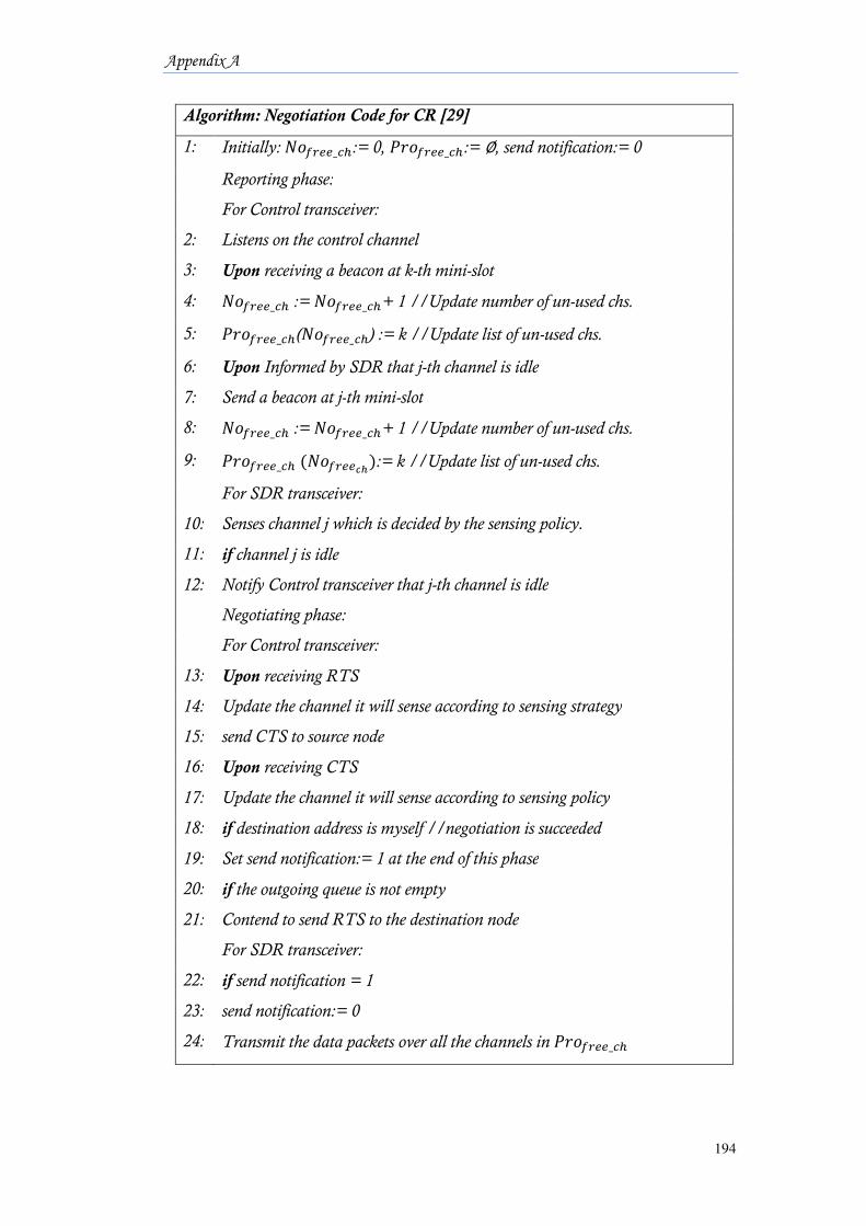
Appendix A
194
Algorithm: Negotiation Code for CR [29]
1: Initially:������_��:= 0, ������_��:= ∅, send notification:= 0
Reporting phase:
For Control transceiver:
2: Listens on the control channel
3: Upon receiving a beacon at k-th mini-slot
4: ������_�� := ������_��+ 1 //Update number of un-used chs.
5: ������_��(������_��) := k //Update list of un-used chs.
6: Upon Informed by SDR that j-th channel is idle
7: Send a beacon at j-th mini-slot
8: ������_�� := ������_��+ 1 //Update number of un-used chs.
9: ������_��(��������):= k //Update list of un-used chs.
For SDR transceiver:
10: Senses channel j which is decided by the sensing policy.
11: if channel j is idle
12: Notify Control transceiver that j-th channel is idle
Negotiating phase:
For Control transceiver:
13: Upon receiving RTS
14: Update the channel it will sense according to sensing strategy
15: send CTS to source node
16: Upon receiving CTS
17: Update the channel it will sense according to sensing policy
18: if destination address is myself //negotiation is succeeded
19: Set send notification:= 1 at the end of this phase
20: if the outgoing queue is not empty
21: Contend to send RTS to the destination node
For SDR transceiver:
22: if send notification = 1
23: send notification:= 0
24: Transmit the data packets over all the channels in ������_��