
Radio - Engineering Class Home Pages · Radio Radio link design. VDL4 Radio, Toulouse/Page 2 ......
35
VDL4 Radio, Toulouse/Page 1(xx) 2000-06-13/FQ Radio Radio link design
Transcript of Radio - Engineering Class Home Pages · Radio Radio link design. VDL4 Radio, Toulouse/Page 2 ......

VDL4 Radio, Toulouse/Page 1(xx)2000-06-13/FQ
Radio
Radio link design

VDL4 Radio, Toulouse/Page 2(xx)2000-06-13/FQ
Overview
• VDL Mode 4• A (radio) communication system• The radio channel• Channel access

VDL4 Radio, Toulouse/Page 3(xx)2000-06-13/FQ
VDL Mode 4 Ground station
VHF TransceiverCommunication
Processor GNSS reference receiver

VDL4 Radio, Toulouse/Page 4(xx)2000-06-13/FQ
VHF TransceiverCommunication
Processor
VDL Mode 4 Transponder
GNSS receiver

VDL4 Radio, Toulouse/Page 5(xx)2000-06-13/FQ
VDL Mode 4 Superframe - 1 minute - 4,500 slots = 75 slots/s
13.33 msSlot 1 Slot 4500
Slot 4501 Slot 9000
Current superframe
Current superframe + 1
VDL4 Radio, Toulouse/Page 6(xx)2000-06-13/FQ
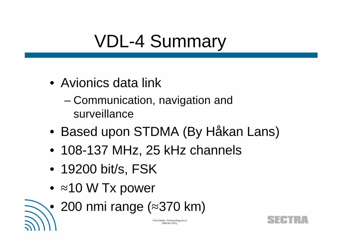
VDL-4 Summary
• Avionics data link– Communication, navigation and
surveillance
• Based upon STDMA (By Håkan Lans)• 108-137 MHz, 25 kHz channels• 19200 bit/s, FSK• ≈10 W Tx power• 200 nmi range (≈370 km)

VDL4 Radio, Toulouse/Page 7(xx)2000-06-13/FQ
Communication layers
Physical
Data link
Network
Transport
Presentation
OSI LAN examples
HTTP, FTP
TCP
IP
Ethernet, ATM
Twisted pair
Data delivery
Packets
Frames
Raw bits
VDL4
xx
xx
vv
STDMA
VHF channel
Session
Application
Process
Transform /translate
User interface Web browser... CDTI(Cockpit display of traffic information)
ADS-B
TIS-B
DLS

VDL4 Radio, Toulouse/Page 8(xx)2000-06-13/FQ
Power level units
• dB: Logarithmic level ratio:– 3 dB ↔ double power– 10 db ↔ 10 * power
• dBm: Power level, 0 dBm = 1 mW• dBi: Antenna gain, 0 dBi => isotropic ant• dBc: Power level, 0 dBc => carrier level• dBµV: Voltage level, 0dBµV = 1 µV• dBµV/m: Field strength

VDL4 Radio, Toulouse/Page 9(xx)2000-06-13/FQ
The radio spectrum
100 MHz 1 GHz 10 GHz
FM radio VDL-4 GSM 900
1 MHz 1015Hz1 kHz0Hz 1 GHz 1 THz 1018Hz 1021Hz 1024Hz
VLF LF MF HF VHF UHF SHF EHF Infrared Visible Ultraviolett Gamma-ray Cosmic-ray
Infrasonics Sonics
Ultra sonics Microwaves Infrared X-ray Cosmic-ray
Radio spectrum3 kHz 300 GHz
NG W-LAN5.8±0.752.45±0.5
BluetoothW-LAN
1160 * 25 kHz channels 108MHz 137MHz
. . .
Spectrum mask
1:st 2:nd 4:th 32:nd2 dBm -28 dBm -38 dBm -53 dBm≈45 dBm

VDL4 Radio, Toulouse/Page 10(xx)2000-06-13/FQ
Frequency issues
• Attenuation ~ f2 ( Pr/Pt = GrGtλ2/(4πr)2 )– 81 times more power required at 900MHz
for same received power as at 100MHz
• Antenna size ~ f– Typically 70 cm for FM λ/4 antenna (100
Mhz)– ≈ 8 cm for 900 MHz λ/4 antenna– Efficient (VHF) antenna can have ≈ 0 dBi
(typical aircraft antenna ≈-4 dBi)

VDL4 Radio, Toulouse/Page 11(xx)2000-06-13/FQ
Noise
• Thermal background noise– -174 dBm/Hz @ 290K (0 dB NF)
• Sky temperature– Significant (NF ≈ 5-10 dB) at low
frequencies (< 200 MHz)
• Other systems (man made)– Impulse and continuous signal (CW)
• Noise figure NF = 10log(1+T/290)Temperature T in Kelvin

VDL4 Radio, Toulouse/Page 12(xx)2000-06-13/FQ
Noise
100 MHz 1 GHz
NF dB
1
2
3
4
5Typical sky temperature
Thermal noise floor (-174 dBm/Hz @ 290K)0

VDL4 Radio, Toulouse/Page 13(xx)2000-06-13/FQ
Noise
• CCI: Co-channel interference– In-band interference– Typically 6-20 dB CCI rejection– Interference from other similar units using
same channel– Low CCI ratio => more efficient frequency
reuse– 10 dB CCI protection will be required for
VDL-4
VDL4 Radio, Toulouse/Page 14(xx)2000-06-13/FQ
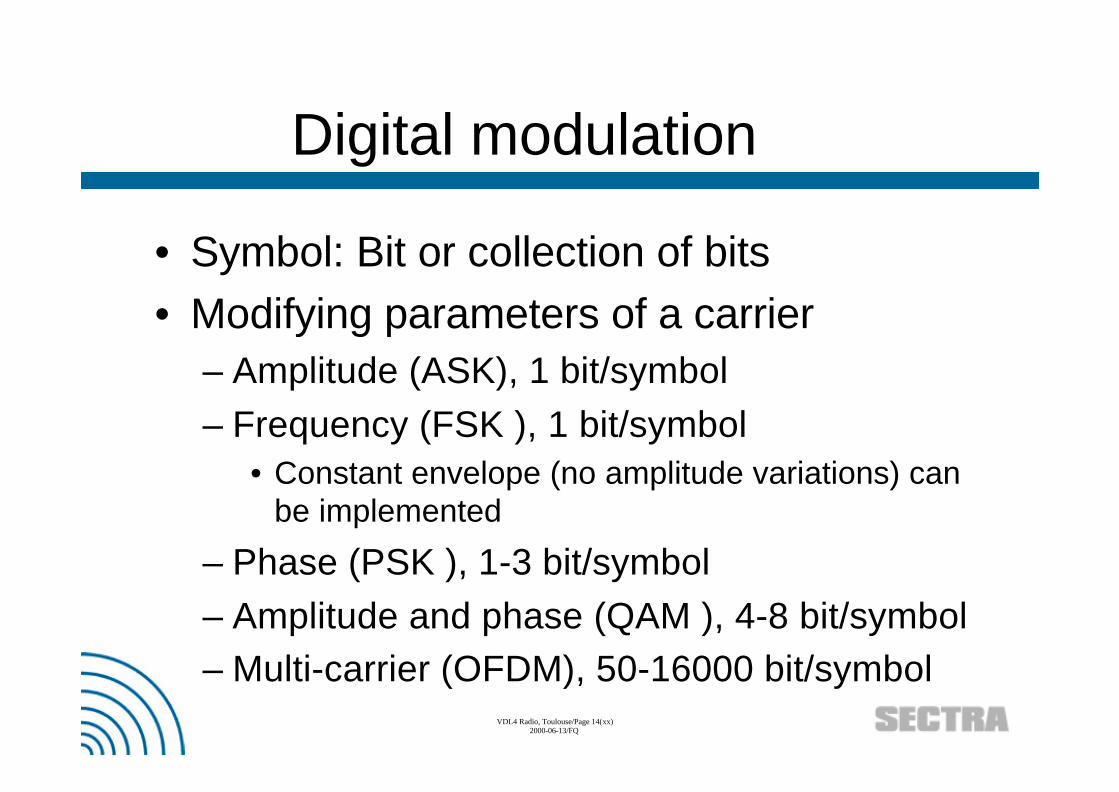
Digital modulation
• Symbol: Bit or collection of bits• Modifying parameters of a carrier
– Amplitude (ASK), 1 bit/symbol– Frequency (FSK ), 1 bit/symbol
• Constant envelope (no amplitude variations) canbe implemented
– Phase (PSK ), 1-3 bit/symbol– Amplitude and phase (QAM ), 4-8 bit/symbol– Multi-carrier (OFDM), 50-16000 bit/symbol

VDL4 Radio, Toulouse/Page 15(xx)2000-06-13/FQ
Metrics
• Power efficiency– Signal power to achieve a particular BER
for a given modulation scheme– Signal energy per bit / noise spectral
density: Eb / N0
• Bandwidth (spectral) efficiency– Possible data rate for given bandwidth– Data rate typically 0.5-4 bit/s/Hz– Shannon limit: C = B * log2(1+s/n)

VDL4 Radio, Toulouse/Page 16(xx)2000-06-13/FQ
Constellation: Vectornotation
• Representing amplitude and phaseusing polar coordinates
• I = M*cosθ, M: Amplitude, θ: Phase• Q = M*sinθ
I
Q
M
θIn-phase component
Quadrqture component

VDL4 Radio, Toulouse/Page 17(xx)2000-06-13/FQ
Using the vector notation
• ”Detectability”• Crest factor (amplitude variations)• Power and bandwidth efficiency
Peak powerDistance ~ detectability
Log2(number of signals) = bits/symbol ~ bits/s/Hz
Transitions: Indicates amplitude variations

VDL4 Radio, Toulouse/Page 18(xx)2000-06-13/FQ
Transceiver structure
Error controlcoding
Modulator Mixer
RF osc
Filter
Power amp
LNA
PLL
Digital (DSP) Digital and/or analog Analog
Errorcorrection
Demodulator

VDL4 Radio, Toulouse/Page 19(xx)2000-06-13/FQ
Analog design issues
• Filters– Attenuation– Phase linearity
• Mixers and amplifiers– Dynamic range
• Spurious products• Noise
• Oscillators– Phase noise
ffc
Phase noise

VDL4 Radio, Toulouse/Page 20(xx)2000-06-13/FQ
Implementation issues
• For analog components:– Performance costs:
• Money• Size• Power

VDL4 Radio, Toulouse/Page 21(xx)2000-06-13/FQ
Constant envelopemodulation
• FSK, MSK (h=0.5)• Features:
– Frequency reuse (CCI)– Power efficient– Non-linear transmitter
GMSK GFSK(h=0.25)
BPF VCOBits RF
Signalmapping
Filter
Filter
90 degFcBits RF
I
Q

VDL4 Radio, Toulouse/Page 22(xx)2000-06-13/FQ
• D8PSK, QPSK• Features
– High throughput (1.5-3 bit/s/Hz)
D8PSK π/4 DQPSK
Phase modulation
Signalmapping
Filter
Filter
90 degFcBits RF
• Edge (upgraded GSM)(Uses π/16 offset )
• Tetra• IS-54 (NA Dig Cellular)• Japanese Dig Cellular• Japanese PHP

VDL4 Radio, Toulouse/Page 23(xx)2000-06-13/FQ
• 16 QAM, 64 QAM, 256 QAM• Features
– High throughput (3-8 bit/s/Hz)16 QAM
Phase/Amplitudemodulation
Signalmapping
Filter
Filter
90 degFcBits RF
• Microwave links

VDL4 Radio, Toulouse/Page 24(xx)2000-06-13/FQ
Multi-carrier modulation
• OFDM, COFDM, MC-CDMA• Multiple orthogonal carriers, typically
PSK or QAM modulated• Coding in the frequency dimension• For N carriers, symbol time increases
by N– Less ISI (intersymbol interference)
• Less sensitive to multipath interference

VDL4 Radio, Toulouse/Page 25(xx)2000-06-13/FQ
DS-CDMA modulation
• Direct sequence CDMA– Spreading gain W/R– Rake receiver (“ISI-free”)
Carrier Spreadingsequence
Power amp
BPSK
W/R = 10 log(1.2288 MHz/9600Hz) = 21 dB (IS-95 CDMAW = Spreading bandwidth, R = data rate

VDL4 Radio, Toulouse/Page 26(xx)2000-06-13/FQ
Performance
• Spectrum use Error rates
Power
ffc
SNR
BER
10-1
10-2
10-3
10-4
10-5
10-0
2 4 6 8 10 12 14
Typ. ≈1-1.5 * symbol rate FEC gain ≈ 2-10 dB
FECNo FEC

VDL4 Radio, Toulouse/Page 27(xx)2000-06-13/FQ
-3 dB
Gt: -2 dB Gr: -2 dB
-3 dB
Att: 127 dB
PALNA
•Antenna gain: -2dBi (Tx and Rx)•Cable loss: 3dB (Tx and RX)•Thermal noise: -174dBm/Hz•Sky temp: NF∼4dB•Man-made noise 16dB ENR•U=4,359 * 106 * Er * √GR / f•U= √PR
•Bandwidth: 25 kHz = 44 dB•Rx Input NF: 12dB•Rx SNR required: 12 dB
•Distance 200 nmi (370 km)•Carrier frequency: 137 MHz•Signal attenuation: 127dB
Link budget
NF: 12dB
Power ?

VDL4 Radio, Toulouse/Page 28(xx)2000-06-13/FQ
Link budget
PA power: 29+2+3=34dBm (2.5W)Required signal level into antenna: -103+2+3= -98dBm
Noise into RX antenna: Man-made + Sky temp: Tenr=11835K, Tsky=1018K, Tot: 12853K => 4064K at LNA
LNA NF (12 dB) => Teq= (1012/10-1)*290 = 4306K
Cascaded noise factor: Feq = F1 + (F2-1)/G1 + (F3-1)/G1G2+ … + (Fn-1)/G1G2 … Gn-1
Cascaded noise temperature: Teq = T1 + T/G1 + T3/G1G2+ … + Tn/G1G2 … Gn-1
Te = (10NF/10 -1) T0 NF = Noise figure, T0 =290K, Te=equivalent noise tempTenr = (10ENR/10+1) T0
Total T at LNA = 4306+4064=8370K => F=30 (NF=15dB)
Noise power at LNA = -174+44+15= -115dBm
Signal level at LNA: -115+12 = -103dBm for 12 db SNR
A= -3 dB
Gt: -2 dBGr: -2 dB
A= -3 dB
Att: 127 dB
PALNA
NF=12dB
Transmitted power: -98+127=29dBm

VDL4 Radio, Toulouse/Page 29(xx)2000-06-13/FQ
Multi-access system FDMA
Time
Frequency •Central coordination
•Analog systems•POTS, FM-radio, VHF

VDL4 Radio, Toulouse/Page 30(xx)2000-06-13/FQ
Multi-access system “Aloha”
Time
User•No coordination•Low channelutilization
•Mode-S, UAT
VDL4 Radio, Toulouse/Page 31(xx)2000-06-13/FQ
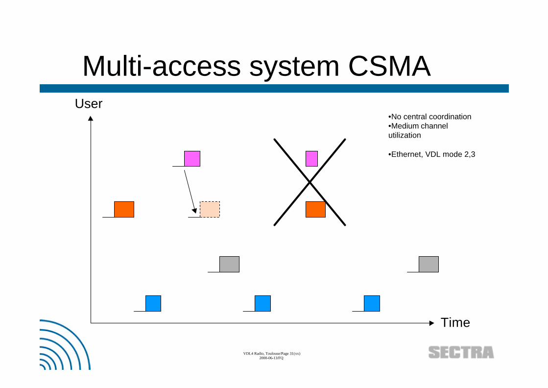
Multi-access system CSMA
Time
User•No central coordination•Medium channelutilization
•Ethernet, VDL mode 2,3

VDL4 Radio, Toulouse/Page 32(xx)2000-06-13/FQ
Multi-access system TDMA
Time
•Coordination of slots
•GSM, DECT...•VDL4 (STDMA)

VDL4 Radio, Toulouse/Page 33(xx)2000-06-13/FQ
Multi-access system FH-CDMA
Time
Frequency •Coordination by codes
•Bluetooth, Radio-LAN•Military systems

VDL4 Radio, Toulouse/Page 34(xx)2000-06-13/FQ
Multi-access system DS-CDMA
Time
Frequency
•Coordination by codes
•IS-95 (US CDMA), GPS• Users use different spreadingsequences with low cross-correlation

VDL4 Radio, Toulouse/Page 35(xx)2000-06-13/FQ
SECTRA Wireless Technologies 2000SECTRA Wireless Technologies 2000http://www.http://www.sectrasectra.se/wireless.se/wireless
Make it simple...


![FM Microwave Radio Link - Elber radio TV broadcast …UserManuals~NBFM_[EN].pdfFM Microwave Radio Link Transmitter T_NBFM-01 ... microwave radio link. It is able to transfer, over](https://static.fdocuments.us/doc/165x107/5ab9bcd47f8b9aa6018e34cf/fm-microwave-radio-link-elber-radio-tv-broadcast-usermanualsnbfmenpdffm.jpg)