Radio Antennas and Broadcast Components - Home … Antennas and Broadcast Components Products...
73
Radio Antennas and Broadcast Components Engineering Excellence since 1942
Transcript of Radio Antennas and Broadcast Components - Home … Antennas and Broadcast Components Products...

Radio Antennas and Broadcast Components
Engineering Excellence since 1942
222 Tower Road, P.O. Box 949, Raymond, ME 04071 • 207-655-8100 • 1-800-341-9678 • Fax: 207-655-8177 • www.dielectric.comDielectric • 22 Tower Rd., Raymond, ME 04071 USA • +1 207-655-8100 • www.dielectric.com • FM07/2013
Radio Antennas and Broadcast Components
Products contained in this catalog may be covered by one or more of the following patents:
6,917,264; 6,887,093; 6,882,224; 6,870,443; 6,867,743; 6,816,040; 6,703,984; 6,703,911; 6,677,916; 6,650,300; 6,650,209; 6,617,940; 6,538,529; 6,373,444; 6,320,555; 5,999,145; 5,861,858; 5,455,548; 5,418,545; 5,401,173; 5,167,510; 4,988,961; 4,951,013; 4,899,165; 4,723,307; 4,654,962; 4,602,227; 7,084,822; 7,081,860; 7,061,441; 7,034,545; 7,012,574; 6,972,731; 6,972,648; 6,961,027; 6,914,579; 6,441,796; 7,102,589;
Additonal patents are pending.
Table of Contents
HD RadioTM* Antennas HDR Series Interleaved Antenna . . . . . . . . . . . . . . . . . . . . . . . . . . . . . . . . . . . . . . . 4 Multi-station HDFMVee . . . . . . . . . . . . . . . . . . . . . . . . . . . . . . . . . . . . . . . . . . . . . . . . . . . . . . . . . . . . . 5 HDFDM . . . . . . . . . . . . . . . . . . . . . . . . . . . . . . . . . . . . . . . . . . . . . . . . . . . . . . . . . . . . . . . 8 HDCBR . . . . . . . . . . . . . . . . . . . . . . . . . . . . . . . . . . . . . . . . . . . . . . . . . . . . . . . . . . . . . . .11 FMVee . . . . . . . . . . . . . . . . . . . . . . . . . . . . . . . . . . . . . . . . . . . . . . . . . . . . . . . . . . . . . . . 13 CBR . . . . . . . . . . . . . . . . . . . . . . . . . . . . . . . . . . . . . . . . . . . . . . . . . . . . . . . . . . . . . . . . . 16
Multi-station Antennas DCR-Q . . . . . . . . . . . . . . . . . . . . . . . . . . . . . . . . . . . . . . . . . . . . . . . . . . . . . . . . . . . . . . . . . . . 18 DCR-S / HDR-S . . . . . . . . . . . . . . . . . . . . . . . . . . . . . . . . . . . . . . . . . . . . . . . . . . . . . . . . . . 20 DCR-MFE Funky Elbow . . . . . . . . . . . . . . . . . . . . . . . . . . . . . . . . . . . . . . . . . . . . . . . . . . . 23 DCR-M / HDR-M . . . . . . . . . . . . . . . . . . . . . . . . . . . . . . . . . . . . . . . . . . . . . . . . . . . . . . . . . 25 DCR-MT . . . . . . . . . . . . . . . . . . . . . . . . . . . . . . . . . . . . . . . . . . . . . . . . . . . . . . . . . . . . . . . . . . 28 DCR-C / HDR-C . . . . . . . . . . . . . . . . . . . . . . . . . . . . . . . . . . . . . . . . . . . . . . . . . . . . . . . . . 29 DCR-H / HDR-H . . . . . . . . . . . . . . . . . . . . . . . . . . . . . . . . . . . . . . . . . . . . . . . . . . . . . . . . . 32
Broadband Systems for Multiplexing Signals DCR-S / DCR-M . . . . . . . . . . . . . . . . . . . . . . . . . . . . . . . . . . . . . . . . . . . . . . . . . . . . . . . . . 35
Full Band Master or Auxiliary FM Antennas DCR-S / DCR-M . . . . . . . . . . . . . . . . . . . . . . . . . . . . . . . . . . . . . . . . . . . . . . . . . . . . . . . . . 37
Single Station Antennas DCR-L . . . . . . . . . . . . . . . . . . . . . . . . . . . . . . . . . . . . . . . . . . . . . . . . . . . . . . . . . . . . . . . . . . . . 39 DCR-T . . . . . . . . . . . . . . . . . . . . . . . . . . . . . . . . . . . . . . . . . . . . . . . . . . . . . . . . . . . . . . . . . . . . 41 DCV . . . . . . . . . . . . . . . . . . . . . . . . . . . . . . . . . . . . . . . . . . . . . . . . . . . . . . . . . . . . . . . . . . . . . . 43
Panel Antenna DCPJ . . . . . . . . . . . . . . . . . . . . . . . . . . . . . . . . . . . . . . . . . . . . . . . . . . . . . . . . . . . . . . . . . . . . . 44
Pattern Study and Optimization . . . . . . . . . . . . . . . . . . . . . . . . . . . . . . . . . . . . . . . 47
Elevation Patterns . . . . . . . . . . . . . . . . . . . . . . . . . . . . . . . . . . . . . . . . . . . . . . . . . . . . . . 49
RFR Considerations . . . . . . . . . . . . . . . . . . . . . . . . . . . . . . . . . . . . . . . . . . . . . . . . . . . . 50
Filters and Combiners . . . . . . . . . . . . . . . . . . . . . . . . . . . . . . . . . . . . . . . . . . . . . . . . . 51
Monitoring . . . . . . . . . . . . . . . . . . . . . . . . . . . . . . . . . . . . . . . . . . . . . . . . . . . . . . . . . . . . . . 68
Accessories . . . . . . . . . . . . . . . . . . . . . . . . . . . . . . . . . . . . . . . . . . . . . . . . . . . . . . . . . . . . . 69*HD RadioTM is a trademark of iBiquity Digital Corporation.
Specifications are subject to change without notice.
322 Tower Road, P.O. Box 949, Raymond, ME 04071 • 207-655-8100 • 1-800-341-9678 • Fax: 207-655-8177 • www.dielectric.comDielectric • 22 Tower Rd., Raymond, ME 04071 USA • +1 207-655-8100 • www.dielectric.com • FM07/2013
Leading the broadcast industry since 1942
Dielectric is a world leader in the engineering, design, and manufacture of complete broadcast systems for TV, FM, HF and MF. Our strength is in the development of custom solutions that fit our customer’s unique requirements.
Single source of responsibility for your FM system
We manufacture a full complement of products, including a variety of proprietary of-ferings, from the transmitter output to the tower top including antennas, filter/com-biner systems, and switches. Products unique to the Dielectric product line include digiTLineTM, EHTLineTM, and HDR Series antennas. Our service offerings include system monitoring, tower mapping, modifications and complete installation and maintenance services. If needed, we have the resources to respond to your emergency situation.
Digital Radio
More digital television broadcasters have chosen Dielectric brand products than all other manufacturers combined. We are applying our expertise in digital television technology to the unique needs of the FM broadcaster. We continue to develop innovative solutions for FM broadcasters as they transition to digital.
Whether your needs are for a digital, analog or combined antenna, filter, combiner, or complete system including installation and monitoring services, Dielectric would like the opportunity to offer you solutions engineered to meet your specific needs.
All Dielectric FM antenna and filter products are compatible with passing the HD signal.
Guaranteed quality and reliability
Dielectric is so confident in our products’ performance that we offer the best war-ranty in the business, covering everything from the transmitter output through the switches, filters, combiner, transmission line, and antenna.
Unique RF products for better broadcast quality
We offer combiner systems that have better frequency response, lower insertion loss, and lower group delay variation than that of other manufacturers. For the broadcaster, this means a clearer signal now and digital capabilities later. Dielectric also manufactures advanced antennas with variable bay spacing for better control of elevation and azimuth patterns.
FM Resources
422 Tower Road, P.O. Box 949, Raymond, ME 04071 • 207-655-8100 • 1-800-341-9678 • Fax: 207-655-8177 • www.dielectric.comDielectric • 22 Tower Rd., Raymond, ME 04071 USA • +1 207-655-8100 • www.dielectric.com • FM07/2013
HD Radio
HDR Series Interleaved FM Array1
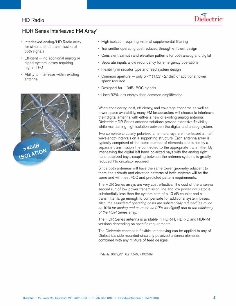
When considering cost, efficiency, and coverage concerns as well as tower space availability, many FM broadcasters will choose to interleave their digital antenna with either a new or existing analog antenna. Dielectric HDR Series antenna solutions provide extensive flexibility while maintaining high isolation between the digital and analog system.
Two complete circularly polarized antenna arrays are interleaved at half wavelength intervals on a supporting structure. Each antenna array is typically comprised of the same number of elements, and is fed by a separate transmission line connected to the appropriate transmitter. By interleaving the digital left hand-polarized bays with the analog right hand polarized bays, coupling between the antenna systems is greatly reduced. No circulator required!
Since both antennas will have the same tower geometry adjacent to them, the azimuth and elevation patterns of both systems will be the same and will meet FCC and predicted pattern requirements.
The HDR Series arrays are very cost effective. The cost of the antenna, second run of low power transmission line and low power circulator is substantially less than the system cost of a 10 dB coupler and a transmitter large enough to compensate for additional system losses. Also, the associated operating costs are substantially reduced (as much as 10% for analog and as much as 90% for digital) due to the efficiency of the HDR Series array.
The HDR Series antenna is available in HDR-H, HDR-C and HDR-M versions depending on specific requirements.
The Dielectric concept is flexible. Interleaving can be applied to any of Dielectric's side mounted circularly polarized antenna elements combined with any mixture of feed designs.
1Patents: 6,972,731; 6,914,579; 7,102,589
• Interleaved analog/HD Radio array for simultaneous transmission of both signals
• Efficient — no additional analog or digital system losses requiring higher TPO
• Ability to interleave within existing antenna
• High isolation requiring minimal supplemental filtering
• Transmitter operating cost reduced through efficient design
• Consistent azimuth and elevation patterns for both analog and digital
• Separate inputs allow redundancy for emergency operations
• Flexibility in radiator type and feed system design
• Common aperture — only 5'-7' (1.52 - 2.13m) of additional tower space required
• Designed for -10dB IBOC signals
• Uses 33% less energy than common amplification
>40dB
IsolatIon
522 Tower Road, P.O. Box 949, Raymond, ME 04071 • 207-655-8100 • 1-800-341-9678 • Fax: 207-655-8177 • www.dielectric.comDielectric • 22 Tower Rd., Raymond, ME 04071 USA • +1 207-655-8100 • www.dielectric.com • FM07/2013
Multi-station Panel Antennas
HDFMVee
• Full 20 MHz bandwidth• Power ratings up to 10 class C stations• Stainless steel element for excellent
reliability• Designed for -10dB IBOC signals
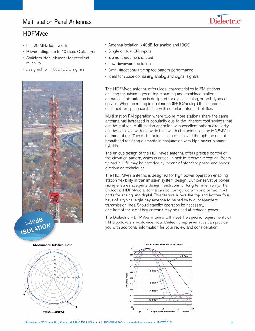
The HDFMVee antenna offers ideal characteristics to FM stations desiring the advantages of top mounting and combined station operation. This antenna is designed for digital, analog, or both types of service. When operating in dual mode (IBOC/analog) this antenna is designed for space combining with superior antenna isolation.
Multi-station FM operation where two or more stations share the same antenna has increased in popularity due to the inherent cost savings that can be realized. Multi-station operation with excellent pattern circularity can be achieved with the wide bandwidth characteristics the HDFMVee antenna offers. These characteristics are achieved through the use of broadband radiating elements in conjunction with high power element hybrids.
The unique design of the HDFMVee antenna offers precise control of the elevation pattern, which is critical in mobile receiver reception. Beam tilt and null fill may be provided by means of standard phase and power distribution techniques.
The HDFMVee antenna is designed for high power operation enabling station flexibility in transmission system design. Our conservative power rating ensures adequate design headroom for long-term reliability. The Dielectric HDFMVee antenna can be configured with one or two input ports for analog and digital. This feature allows the top and bottom four bays of a typical eight bay antenna to be fed by two independent transmission lines. Should standby operation be necessary, one half of the eight bay antenna may be used at reduced power.
The Dielectric HDFMVee antenna will meet the specific requirements of FM broadcasters worldwide. Your Dielectric representative can provide you with additional information for your review and consideration.
1
0.9
0.8
0.7
0.6
0.5
0.4
0.3
0.2
0.1
03 -1 -5 -9 -13
Up Angle from Horizontal Down
CALCULATED ELEVATION PATTERN
Rel
ativ
e Fi
eld
4 Bay
6 Bay
8 Bay
10 Bay
12 Bay
-30 -25 -15-20 -10 -5 0
0
-5
-10
-15
-20
-25
-30
V
H
Measured Relative Field
FMVee-03FM
• Antenna isolation >40dB for analog and IBOC• Single or dual EIA inputs• Element radome standard• Low downward radiation• Omni-directional free space pattern performance• Ideal for space combining analog and digital signals
>40dB
IsolatIon
622 Tower Road, P.O. Box 949, Raymond, ME 04071 • 207-655-8100 • 1-800-341-9678 • Fax: 207-655-8177 • www.dielectric.comDielectric • 22 Tower Rd., Raymond, ME 04071 USA • +1 207-655-8100 • www.dielectric.com • FM07/2013
Multi-station Panel Antennas
HDFMVee
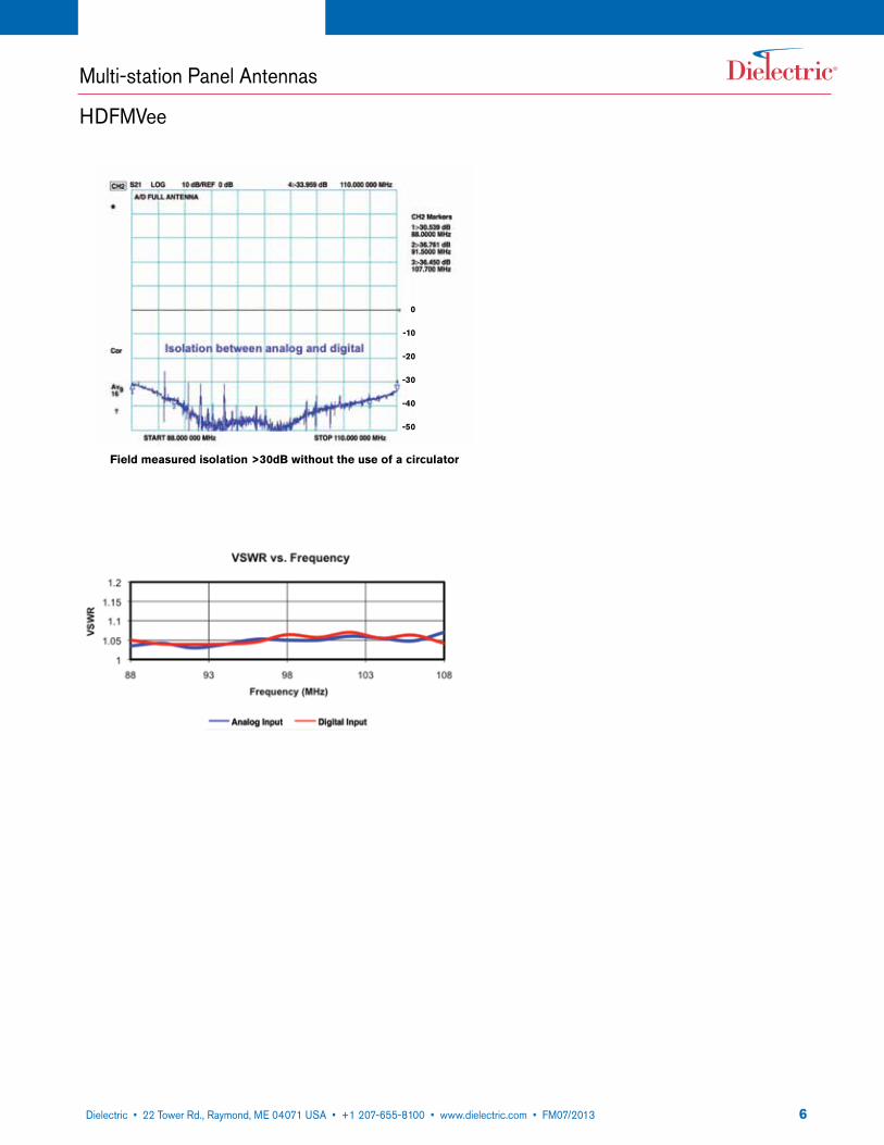
Field measured isolation >30dB without the use of a circulator
0
-10
-20
-30
-40
-50
722 Tower Road, P.O. Box 949, Raymond, ME 04071 • 207-655-8100 • 1-800-341-9678 • Fax: 207-655-8177 • www.dielectric.comDielectric • 22 Tower Rd., Raymond, ME 04071 USA • +1 207-655-8100 • www.dielectric.com • FM07/2013
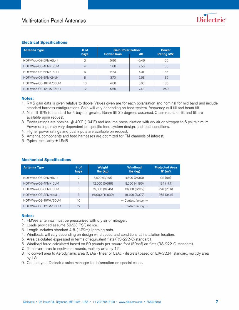
Mechanical Specifications
Antenna Type # of Weight Windload Projected Area bays lbs (kg) lbs (kg) ft2 (m2)
HDFMVee-O3-2FM/6U-1 2 6,500 (2,958) 4,600 (2,093) 92 (8.5)
HDFMVee-O3-4FM/12U-1 4 12,500 (5,688) 9,200 (4,186) 184 (17.1)
HDFMVee-O3-6FM/18U-1 6 19,000 (8,645) 13,800 (6,279) 276 (25.6)
HDFMVee-O3-8FM/24U-1 8 26,000 (11,830) 18,400 (8,372) 368 (34.2)
HDFMVee-O3-10FM/30U-1 10 — Contact factory —
HDFMVee-O3-12FM/36U-1 12 — Contact factory —
Notes:1. FMVee antennas must be pressurized with dry air or nitrogen. 2. Loads provided assume 50/33 PSF, no ice. 3. Length includes standard 4 ft. (1.22m) lightning rods. 4. Windloads will vary depending on design wind speed and conditions at installation location. 5. Area calculated expressed in terms of equivalent flats (RS-222-C-standard).6. Windload force calculated based on 50 pounds per square foot (50psf) on flats (RS-222-C-standard).7. To convert area to equivalent rounds, multiply area by 1.5.8. To convert area to Aerodynamic area (CaAa - linear or CaAc - discrete) based on EIA-222-F standard, multiply area
by 1.8. 9. Contact your Dielectric sales manager for information on special cases.
Multi-station Panel Antennas
Electrical Specifications
Antenna Type # of Gain Polarization1 Power bays Power Gain dB Rating kW3
HDFMVee-O3-2FM/6U-1 2 0.90 -0.46 125
HDFMVee-O3-4FM/12U-1 4 1.80 2.56 135
HDFMVee-O3-6FM/18U-1 6 2.70 4.31 185
HDFMVee-O3-8FM/24U-1 8 3.70 5.68 185
HDFMVee-O3-10FM/30U-1 10 4.60 6.63 185
HDFMVee-O3-12FM/36U-1 12 5.60 7.48 250
Notes:1. RMS gain data is given relative to dipole. Values given are for each polarization and nominal for mid band and include
standard harness configurations. Gain will vary depending on feed system, frequency, null fill and beam tilt. 2. Null fill 10% is standard for 4 bays or greater. Beam tilt .75 degrees assumed. Other values of tilt and fill are
available upon request. 3. Power ratings are nominal @ 40˚C (104˚F) and assume pressurization with dry air or nitrogen to 5 psi minimum.
Power ratings may vary dependent on specific feed system design, and local conditions. 4. Higher power ratings and dual inputs are available on request. 5. Antenna components and feed harnesses are optimized for FM channels of interest. 6. Typical circularity ±1.5dB
822 Tower Road, P.O. Box 949, Raymond, ME 04071 • 207-655-8100 • 1-800-341-9678 • Fax: 207-655-8177 • www.dielectric.comDielectric • 22 Tower Rd., Raymond, ME 04071 USA • +1 207-655-8100 • www.dielectric.com • FM07/2013
Multi-station Panel Antennas
HDFDM
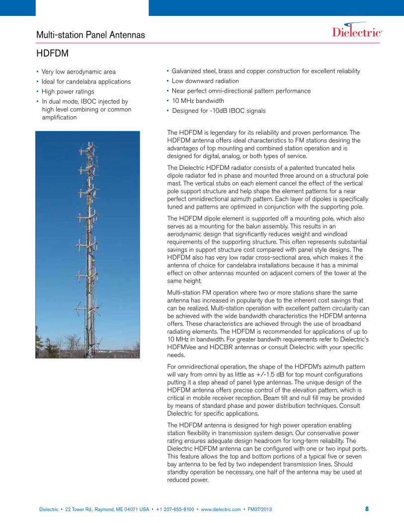
The HDFDM is legendary for its reliability and proven performance. The HDFDM antenna offers ideal characteristics to FM stations desiring the advantages of top mounting and combined station operation and is designed for digital, analog, or both types of service.
The Dielectric HDFDM radiator consists of a patented truncated helix dipole radiator fed in phase and mounted three around on a structural pole mast. The vertical stubs on each element cancel the effect of the vertical pole support structure and help shape the element patterns for a near perfect omnidirectional azimuth pattern. Each layer of dipoles is specifically tuned and patterns are optimized in conjunction with the supporting pole.
The HDFDM dipole element is supported off a mounting pole, which also serves as a mounting for the balun assembly. This results in an aerodynamic design that significantly reduces weight and windload requirements of the supporting structure. This often represents substantial savings in support structure cost compared with panel style designs. The HDFDM also has very low radar cross-sectional area, which makes it the antenna of choice for candelabra installations because it has a minimal effect on other antennas mounted on adjacent corners of the tower at the same height.
Multi-station FM operation where two or more stations share the same antenna has increased in popularity due to the inherent cost savings that can be realized. Multi-station operation with excellent pattern circularity can be achieved with the wide bandwidth characteristics the HDFDM antenna offers. These characteristics are achieved through the use of broadband radiating elements. The HDFDM is recommended for applications of up to 10 MHz in bandwidth. For greater bandwith requirements refer to Dielectric's HDFMVee and HDCBR antennas or consult Dielectric with your specific needs.
For omnidirectional operation, the shape of the HDFDM’s azimuth pattern will vary from omni by as little as +/-1.5 dB for top mount configurations putting it a step ahead of panel type antennas. The unique design of the HDFDM antenna offers precise control of the elevation pattern, which is critical in mobile receiver reception. Beam tilt and null fill may be provided by means of standard phase and power distribution techniques. Consult Dielectric for specific applications.
The HDFDM antenna is designed for high power operation enabling station flexibility in transmission system design. Our conservative power rating ensures adequate design headroom for long-term reliability. The Dielectric HDFDM antenna can be configured with one or two input ports. This feature allows the top and bottom portions of a typical five or seven bay antenna to be fed by two independent transmission lines. Should standby operation be necessary, one half of the antenna may be used at reduced power.
• Very low aerodynamic area• Ideal for candelabra applications• High power ratings• In dual mode, IBOC injected by
high level combining or common amplification
• Galvanized steel, brass and copper construction for excellent reliability• Low downward radiation• Near perfect omni-directional pattern performance• 10 MHz bandwidth• Designed for -10dB IBOC signals
922 Tower Road, P.O. Box 949, Raymond, ME 04071 • 207-655-8100 • 1-800-341-9678 • Fax: 207-655-8177 • www.dielectric.comDielectric • 22 Tower Rd., Raymond, ME 04071 USA • +1 207-655-8100 • www.dielectric.com • FM07/2013
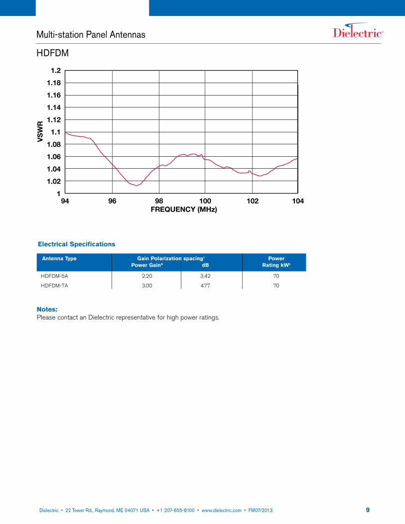
1.2
1.18
1.16
1.14
1.12
1.1
1.08
1.06
1.04
1.02
1 94 96 98 100 102 104
FREQUENCY (MHz)
VS
WR
Multi-station Panel Antennas
HDFDM
Electrical Specifications
Antenna Type Gain Polarization spacing1 Power Power Gain* dB Rating kW3
HDFDM-5A 2.20 3.42 70
HDFDM-7A 3.00 4.77 70
Notes:Please contact an Dielectric representative for high power ratings.

1022 Tower Road, P.O. Box 949, Raymond, ME 04071 • 207-655-8100 • 1-800-341-9678 • Fax: 207-655-8177 • www.dielectric.comDielectric • 22 Tower Rd., Raymond, ME 04071 USA • +1 207-655-8100 • www.dielectric.com • FM07/2013
FM panel antennas are generally utilized in a number of specific situations:• To achieve better azimuth patterns on larger towers than typical side-mounted element arrays can provide. • High power and/or very directional applications• Multi-station or shared facilities.
All antennas are designed specific to the particular needs of the station(s) and to tower limitations. Dielectric will assist the station or consultant in choosing the proper design and configuration to achieve project goals.
All panel antennas contain elements that are DC grounded for lightning protection.
Multi-station Panel Antennas
HDFDM
Mechanical Specifications
Antenna Type # of Weight Windload Projected Area bays lbs (kg) lbs (kg) ft2 (m2)
HDFDM-5A 5 6,200 (2,812) 3,000 (1,360) 60 (5.57)
HDFDM-7A 7 11,400 (5,171) 4,150 (1,882) 83 (7.71)
Notes:1. RMS gain data is given relative to dipole. Values given are for each polarization and nominal for mid band and include
standard harness configurations. Gain will vary depending on feed system, frequency, null fill and beam tilt.2. Null fill is standard for 5 bays or greater.3. Power ratings are nominal @40˚C (104˚F) ambient and assume pressurization with dry air or nitrogen to 5 psi mini-
mum. Power ratings may vary dependent on specific feed system design, and local conditions.4. Higher power ratings and dual inputs are available on request.5. Antenna components and feed harnesses are optimized for FM channels of interest.6. Area calculated expressed in terms of equivalent flats (RS-222-C-standard).7. Windload force calculated based on 50 pounds per square foot (50psf) on flats (RS-222-C-standard).8. To convert area to equivalent rounds, multiply area by 1.5.9. To convert area to Aerodynamic area (CaAa - linear or CaAc - discrete) based on EIA-222-F standard, multiply area
by 1.8.
* Other gain values are available. Please contact factory.

1122 Tower Road, P.O. Box 949, Raymond, ME 04071 • 207-655-8100 • 1-800-341-9678 • Fax: 207-655-8177 • www.dielectric.comDielectric • 22 Tower Rd., Raymond, ME 04071 USA • +1 207-655-8100 • www.dielectric.com • FM07/2013
Multi-station Panel Antennas
HDCBR
• Ideal for multi-station operation• Full 20 MHz bandwidth• High power handling• Very low VSWR• Single or dual EIA inputs• Designed for -10dB IBOC signals
The HDCBR (Cavity Backed Radiator) antenna. It offers ideal characteristics to FM stations desiring the advantages of combined station operation or to stations requiring special directional coverage. The antenna is designed for digital, analog, or both types of service.
The Dielectric HDCBR consists of a crossed dipole radiator fed in phase quadrature and mounted within a square cavity. Rotating RF energy is produced when the cavity is excited by the dipole elements. Cavity size is principally determined by beamwidth requirements. A beamwidth of 90 degrees is required for a 4-around array and 120 degrees is required for a 3-around array (measured at the half-voltage coordinates).
Grid Cavity
The cavity used in the Dielectric circularly polarized FM antenna is a welded steel galvanized grid. The cavity grid is supported from a center mounting plate, which also serves as a mounting for the dipole assembly and for attachment of the unit to the supporting structure. The use of grid cavities and aerodynamic design significantly reduces weight and windload requirements of the supporting structure. This often represents substantial savings in support structure cost compared with other panel style antenna designs.
For omnidirectional operation, the shape of the standard azimuth pattern will vary from omni by less than ±2.0 dB for optimized tower configurations. Stations employing directional arrays will find one of the several patterns available to be ideally suited to their specific needs.
The Dielectric HDCBR antenna is designed for high power operation enabling station flexibility in transmission system design. Our conservative power rating ensures adequate design headroom for long term reliability. The Dielectric HDCBR antenna can be configured with one or two input ports. This feature allows the top and bottom portions of a typical antenna to be fed by two independent transmission lines. Should standby operation be necessary, one half of the system may be used at reduced power.
Multi-station Operation
Multi-station FM operation where two or more stations share the same antenna has increased in popularity due to the inherent cost savings which can be realized. Multi-station operation can be achieved only with the wide bandwidth characteristics the Dielectric CBR antenna offers.
These characteristics are achieved through the use of a broadband radiating element in conjunction with high power hybrid junctions.
Dielectric also offers the associated combining equipment necessary for multi-station operation. Dielectric's experience with multiplexer installations ensures proper combiner operation to optimize the system operation.
• Minimal windloading• Superb azimuth circularity and elevation pattern control to ensure uni-
form coverage• Custom azimuth patterns available• Superior antenna isolation• Ideal for space combining analog and IBOC signals
>40dB
IsolatIon
1222 Tower Road, P.O. Box 949, Raymond, ME 04071 • 207-655-8100 • 1-800-341-9678 • Fax: 207-655-8177 • www.dielectric.comDielectric • 22 Tower Rd., Raymond, ME 04071 USA • +1 207-655-8100 • www.dielectric.com • FM07/2013
1.10
1.09
1.08
1.07
1.06
1.05
1.04
1.03
1.02
1.01
188 90 92 94 96 98 100 102 104 106 108
FREQUENCY
VS
WR
Multi-station Panel Antennas
HDCBR
Azimuth Circularity
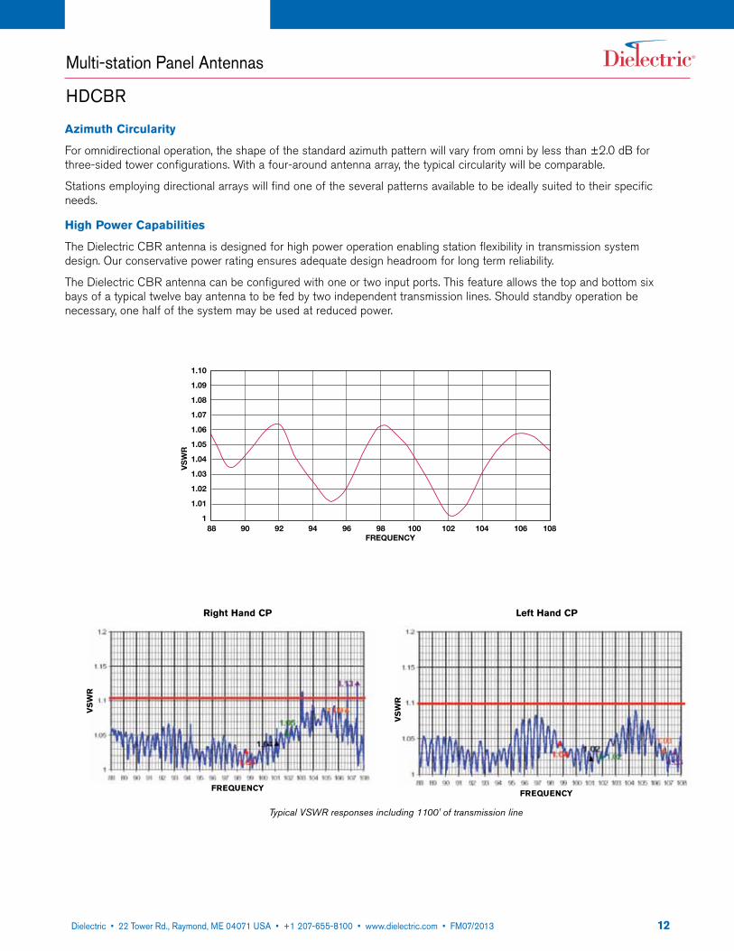
For omnidirectional operation, the shape of the standard azimuth pattern will vary from omni by less than ±2.0 dB for three-sided tower configurations. With a four-around antenna array, the typical circularity will be comparable.
Stations employing directional arrays will find one of the several patterns available to be ideally suited to their specific needs.
High Power Capabilities
The Dielectric CBR antenna is designed for high power operation enabling station flexibility in transmission system design. Our conservative power rating ensures adequate design headroom for long term reliability.
The Dielectric CBR antenna can be configured with one or two input ports. This feature allows the top and bottom six bays of a typical twelve bay antenna to be fed by two independent transmission lines. Should standby operation be necessary, one half of the system may be used at reduced power.
VS
WR
FREqUENCy
VS
WR
FREqUENCy
Right Hand CP Left Hand CP
Typical VSWR responses including 1100' of transmission line
1322 Tower Road, P.O. Box 949, Raymond, ME 04071 • 207-655-8100 • 1-800-341-9678 • Fax: 207-655-8177 • www.dielectric.comDielectric • 22 Tower Rd., Raymond, ME 04071 USA • +1 207-655-8100 • www.dielectric.com • FM07/2013
Multi-station Panel Antennas
FMVee
• Full 20 MHz bandwidth• Power ratings up to 10 class C stations• Stainless steel element for excellent
reliability• Designed for -10dB IBOC signals• Single or dual EIA inputs
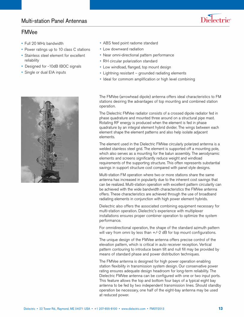
The FMVee (arrowhead dipole) antenna offers ideal characteristics to FM stations desiring the advantages of top mounting and combined station operation.
The Dielectric FMVee radiator consists of a crossed dipole radiator fed in phase quadrature and mounted three around on a structural pipe mast. Rotating RF energy is produced when the element is fed in phase quadrature by an integral element hybrid divider. The wings between each element shape the element patterns and also help isolate adjacent elements.
The element used in the Dielectric FMVee circularly polarized antenna is a welded stainless steel grid. The element is supported off a mounting pole, which also serves as a mounting for the balun assembly. The aerodynamic elements and screens significantly reduce weight and windload requirements of the supporting structure. This often represents substantial savings in support structure cost compared with panel style designs.
Multi-station FM operation where two or more stations share the same antenna has increased in popularity due to the inherent cost savings that can be realized. Multi-station operation with excellent pattern circularity can be achieved with the wide bandwidth characteristics the FMVee antenna offers. These characteristics are achieved through the use of broadband radiating elements in conjunction with high power element hybrids.
Dielectric also offers the associated combining equipment necessary for multi-station operation. Dielectric's experience with multiplexer installations ensures proper combiner operation to optimize the system performance.
For omnidirectional operation, the shape of the standard azimuth pattern will vary from omni by less than +/-2 dB for top mount configurations.
The unique design of the FMVee antenna offers precise control of the elevation pattern, which is critical in auto receiver reception. Vertical pattern contouring to introduce beam tilt and null fill may be provided by means of standard phase and power distribution techniques.
The FMVee antenna is designed for high power operation enabling station flexibility in transmission system design. Our conservative power rating ensures adequate design headroom for long-term reliability. The Dielectric FMVee antenna can be configured with one or two input ports. This feature allows the top and bottom four bays of a typical eight bay antenna to be fed by two independent transmission lines. Should standby operation be necessary, one half of the eight-bay antenna may be used at reduced power.
• ABS feed point radome standard• Low downward radiation• Near omni-directional pattern performance• RH circular polarization standard• Low windload, flanged, top mount design• Lightning resistant – grounded radiating elements• Ideal for commom amplification or high level combining

1422 Tower Road, P.O. Box 949, Raymond, ME 04071 • 207-655-8100 • 1-800-341-9678 • Fax: 207-655-8177 • www.dielectric.comDielectric • 22 Tower Rd., Raymond, ME 04071 USA • +1 207-655-8100 • www.dielectric.com • FM07/2013
The Dielectric antenna test range is one of the few facilities in existence capable of complete antenna testing. The test range transmit and receive transmitters sit on the crest of two hills behind the Dielectric factory. This unique geographical setting offers ideal conditions for testing approaching the “free space” situation of an installed antenna. Here the computer generated azimuth and elevation patterns of a Dielectric antenna can be proven out with highly accurate and sophisticated test equipment – translating the theory of calculated patterns into the reality of actual antenna performance.
The Dielectric FMVee antenna will meet the exacting requirements of FM broadcasters. Your Dielectric representative can provide you with additional information for your review and consideration.
Multi-station Panel Antennas
FMVee
Notes:1. RMS gain data is given relative to dipole. Values given are for each polarization, nominal for mid band and include stan-
dard harness configurations. Gain will vary depending on feed system, frequency, null fill and beam tilt. 2. Null fill 10% is standard for 4 bays or greater. Beam tilt .75 degrees assumed. Other values of tilt and fill are available
upon request. 3. Power ratings are nominal @ 40˚C (104˚F) and assume pressurization with dry air or nitrogen to 5 psi minimum. Power
ratings may vary dependent on specific feed system design, and local conditions. 4. Higher power ratings and dual inputs are available on request.5. Antenna components and feed harnesses are optimized for FM channels of interest.
Electrical Specifications
Model # of RMS Gain RMS Gain Input Max. Avg. Max. Peak Rad. Center bays Ea. Pol. Ea. Pol. Power Windload Above Tower Top (ratio) (ratio) (kW) (kW) (ft) (m)
FMVee-O3-2FM/6U-1 2 .90 -.46 6-50 125 2700 8.83 (2.65)
FMVee-O3-4FM/12U-1 4 1.8 2.56 6-50 135 3300 17.50 (5.25)
FMVee -O3-6FM/18U-1 6 2.7 4.31 6-50 EHT 185 3900 26.16 (7.84)
FMVee O3-8FM/24U-1 8 3.7 5.68 6-50 EHT 185 3900 34.83 (10.45)
FMVee -O3-10FM/30U-1 10 4.6 6.63 6-50 EHT 185 3900 43.50 (13.05)
FMVee -O3-12FM/36U-1 12 5.6 7.48 6-50 EHT Dual 250 6000 52.16 (15.64)
1522 Tower Road, P.O. Box 949, Raymond, ME 04071 • 207-655-8100 • 1-800-341-9678 • Fax: 207-655-8177 • www.dielectric.comDielectric • 22 Tower Rd., Raymond, ME 04071 USA • +1 207-655-8100 • www.dielectric.com • FM07/2013
Notes:1. FMVee antennas must be pressurized with dry air or
nitrogen.2. Loads provided assume TIA/EIA-222-F, 80 mph basic
wind speed, 1,200 ft (360m) tower, 42.6 psf. No ice.3. Length includes standard 4 ft (1.2m) lightning rods.4. Windloads will vary depending on design wind speed &
conditions at installation location.5. Contact your Dielectric sales manager for information
on special cases.
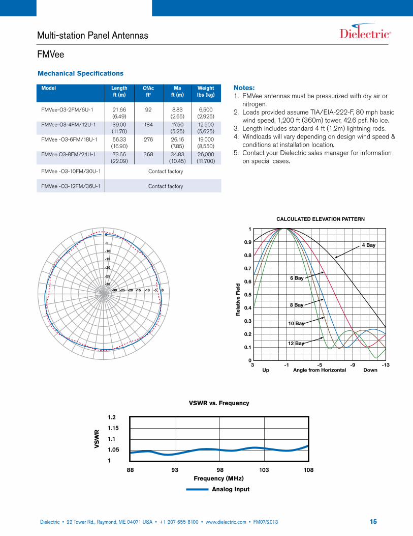
Mechanical Specifications
Model Length CfAc Ma Weight ft (m) ft2 ft (m) lbs (kg)
FMVee-O3-2FM/6U-1 21.66 92 8.83 6,500 (6.49) (2.65) (2,925) FMVee-O3-4FM/12U-1 39.00 184 17.50 12,500 (11.70) (5.25) (5,625) FMVee -O3-6FM/18U-1 56.33 276 26.16 19,000 (16.90) (7.85) (8,550) FMVee O3-8FM/24U-1 73.66 368 34.83 26,000 (22.09) (10.45) (11,700)
FMVee -O3-10FM/30U-1 Contact factory
FMVee -O3-12FM/36U-1 Contact factory
Multi-station Panel Antennas
FMVee
-30
-30 -25 -20 -15 -10 -5 0
-20
-25
-15
-10
-5
01
0.9
0.8
0.7
0.6
0.5
0.4
0.3
0.2
0.1
03 -1 -5 -9 -13
Up Angle from Horizontal Down
CALCULATED ELEVATION PATTERN
Rel
ativ
e Fi
eld
4 Bay
6 Bay
8 Bay
10 Bay
12 Bay
88 93 98 103 108
1.2
1.15
1.1
1.05
1
VSWR vs. Frequency
Frequency (MHz)
VS
WR
Analog Input
1622 Tower Road, P.O. Box 949, Raymond, ME 04071 • 207-655-8100 • 1-800-341-9678 • Fax: 207-655-8177 • www.dielectric.comDielectric • 22 Tower Rd., Raymond, ME 04071 USA • +1 207-655-8100 • www.dielectric.com • FM07/2013
Multi-station Panel Antennas
CBR
• Ideal for multi-station operation• Designed for common amplification
or high level combining• High power handling• Very low VSWR• Minimal windloading
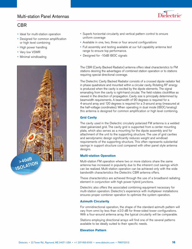
The CBR (Cavity Backed Radiator) antenna offers ideal characteristics to FM stations desiring the advantages of combined station operation or to stations requiring special directional coverage.
The Dielectric Cavity Backed Radiator consists of a crossed dipole radiator fed in phase quadrature and mounted within a circular cavity. Rotating RF energy is produced when the cavity is excited by the dipole elements. The signal emanating from the cavity is right-hand circular. The field rotates clockWise as viewed in the direction of propagation. Cavity size is principally determined by beamwidth requirements. A beamwidth of 90 degrees is required for a 4-around array and 120 degrees is required for a 3-around array (measured at the half-voltage coordinates). When operating in dual mode (IBOC/analog) this antenna is designed for common amplification or high level combining.
Grid Cavity
The cavity used in the Dielectric circularly polarized FM antenna is a welded steel galvanized grid. The cavity grid is supported from a center mounting plate, which also serves as a mounting for the dipole assembly and for attachment of the unit to the supporting structure. The use of grid cavities and aerodynamic design significantly reduces weight and windload requirements of the supporting structure. This often represents substantial savings in support structure cost compared with other panel style antenna designs.
Multi-station Operation
Multi-station FM operation where two or more stations share the same antenna has increased in popularity due to the inherent cost savings which can be realized. Multi-station operation can be achieved only with the wide bandwidth characteristics the Dielectric CBR antenna offers.
These characteristics are achieved through the use of a broadband radiating element in conjunction with high power hybrid junctions.
Dielectric also offers the associated combining equipment necessary for multi-station operation. Dielectric's experience with multiplexer installations ensures proper combiner operation to optimize the system operation.
Azimuth Circularity
For omnidirectional operation, the shape of the standard azimuth pattern will vary from omni by less than ±2.0 dB for three-sided tower configurations. With a four-around antenna array, the typical circularity will be comparable.
Stations employing directional arrays will find one of the several patterns available to be ideally suited to their specific needs.
Elevation Pattern
• Superb horizontal circularity and vertical pattern control to ensure uniform coverage
• Available in one, two, three or four around configurations• Full assembly and testing available at our full capability antenna test
range to ensure top performance.• Designed for -10dB IBOC signals
>40dB
IsolatIon
1722 Tower Road, P.O. Box 949, Raymond, ME 04071 • 207-655-8100 • 1-800-341-9678 • Fax: 207-655-8177 • www.dielectric.comDielectric • 22 Tower Rd., Raymond, ME 04071 USA • +1 207-655-8100 • www.dielectric.com • FM07/2013
Multi-station Panel Antennas
CBR
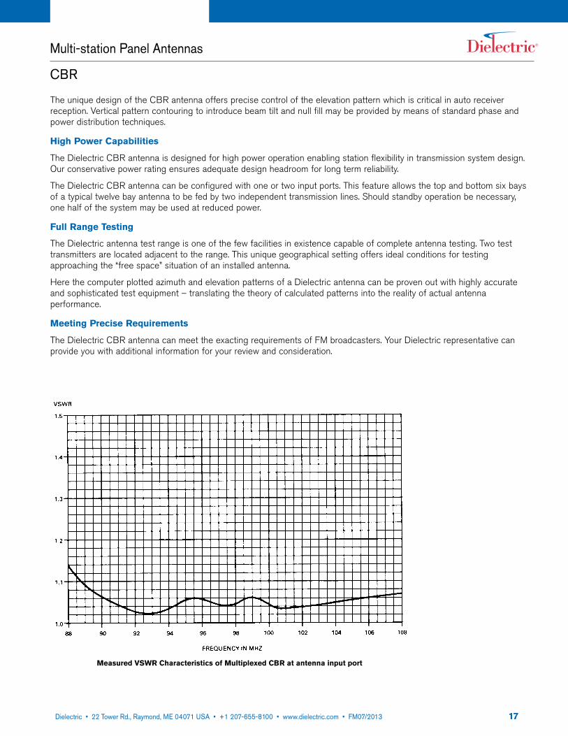
The unique design of the CBR antenna offers precise control of the elevation pattern which is critical in auto receiver reception. Vertical pattern contouring to introduce beam tilt and null fill may be provided by means of standard phase and power distribution techniques.
High Power Capabilities
The Dielectric CBR antenna is designed for high power operation enabling station flexibility in transmission system design. Our conservative power rating ensures adequate design headroom for long term reliability.
The Dielectric CBR antenna can be configured with one or two input ports. This feature allows the top and bottom six bays of a typical twelve bay antenna to be fed by two independent transmission lines. Should standby operation be necessary, one half of the system may be used at reduced power.
Full Range Testing
The Dielectric antenna test range is one of the few facilities in existence capable of complete antenna testing. Two test transmitters are located adjacent to the range. This unique geographical setting offers ideal conditions for testing approaching the “free space” situation of an installed antenna.
Here the computer plotted azimuth and elevation patterns of a Dielectric antenna can be proven out with highly accurate and sophisticated test equipment – translating the theory of calculated patterns into the reality of actual antenna performance.
Meeting Precise Requirements
The Dielectric CBR antenna can meet the exacting requirements of FM broadcasters. Your Dielectric representative can provide you with additional information for your review and consideration.
Measured VSWR Characteristics of Multiplexed CBR at antenna input port

1822 Tower Road, P.O. Box 949, Raymond, ME 04071 • 207-655-8100 • 1-800-341-9678 • Fax: 207-655-8177 • www.dielectric.comDielectric • 22 Tower Rd., Raymond, ME 04071 USA • +1 207-655-8100 • www.dielectric.com • FM07/2013
The DCR-Q was born out of a request to develop a side-mount antenna to support 9 FM stations. Its quadrapole design is an evolution of the popular Dielectric DCR-M antenna. The DCR-Q meets the need of high power broadcasters desiring the azimuth pattern performance of a side-mounted antenna along with the broadband performance and high power handling of a panel. This highly engineered antenna has been specifically developed for multichannel combined applications. We recommend that you consult Dielectric when considering this antenna. Pattern studies are recommended to take full advantage of the azimuth pattern offered by this antenna design.
Multi-Station Operation
The wideband characteristics and high power capacity of the DCR-Q make this antenna an ideal alternative to panel antennas. A variety of custom options are available.
General Specifications:
Pattern Circularity in Free Space: ± 1 dBElement Diameter: 45" (114.3cm)
Construction
The Dielectric DCR-Q element is designed with rugged heavy wall brass tubing. The power dividers and bay feeders are copper and brass construction all designed for long life and reliability. The DCR-Q is a side firing helix design consisting of four dipole elements providing true circular polarization.
Ice stability
Due to the broadband nature of the DCR-Q element, it is inherently stable. Deicers are recommended for applications where heavy icing conditions are anticipated.
Weight and windload
The relative low weight and windload of this antenna makes it ideal for towers that could not otherwise support a master FM panel antenna or for applications where the cost of reinforcing a tower is prohibitive.
Low RF cross section
The low profile of the antenna also makes it an ideal candidate for candelabra applications. When mounted on a small support structure, it has minimal impact on other antennas at the same height.
Beam tilt and null fill
Beam tilt and/or null fill are normally included in arrays of eight bays or more, however, they may also be utilized on smaller arrays. Contact Dielectric and we’ll design an antenna to meet your specific needs.
• 16 MHz bandwidth• Single bay power rating of 35kW• Array input power up to 200 kW• Variable bay spacing• Branch feed for multi-station operation
Multi-station DCR Antennas
DCR-Q
• Circularly polarized• Brass construction• Low ice sensitivity• Low weight and windload• Designed for -10dB IBOC signals
1922 Tower Road, P.O. Box 949, Raymond, ME 04071 • 207-655-8100 • 1-800-341-9678 • Fax: 207-655-8177 • www.dielectric.comDielectric • 22 Tower Rd., Raymond, ME 04071 USA • +1 207-655-8100 • www.dielectric.com • FM07/2013
Multi-station DCR Antennas
DCR-Q
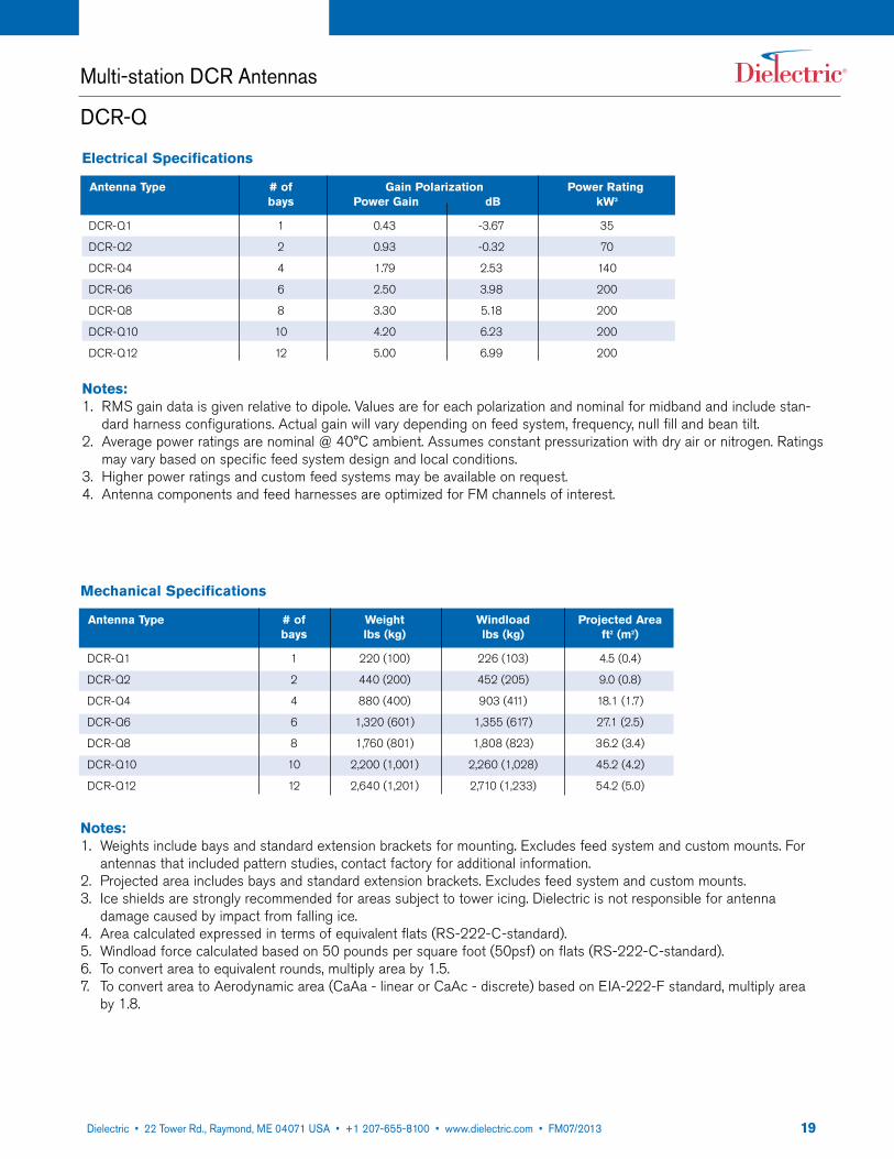
Mechanical Specifications
Antenna Type # of Weight Windload Projected Area bays lbs (kg) lbs (kg) ft2 (m2)
DCR-Q1 1 220 (100) 226 (103) 4.5 (0.4)
DCR-Q2 2 440 (200) 452 (205) 9.0 (0.8)
DCR-Q4 4 880 (400) 903 (411) 18.1 (1.7)
DCR-Q6 6 1,320 (601) 1,355 (617) 27.1 (2.5)
DCR-Q8 8 1,760 (801) 1,808 (823) 36.2 (3.4)
DCR-Q10 10 2,200 (1,001) 2,260 (1,028) 45.2 (4.2)
DCR-Q12 12 2,640 (1,201) 2,710 (1,233) 54.2 (5.0)
Notes:1. Weights include bays and standard extension brackets for mounting. Excludes feed system and custom mounts. For
antennas that included pattern studies, contact factory for additional information.2. Projected area includes bays and standard extension brackets. Excludes feed system and custom mounts.3. Ice shields are strongly recommended for areas subject to tower icing. Dielectric is not responsible for antenna
damage caused by impact from falling ice.4. Area calculated expressed in terms of equivalent flats (RS-222-C-standard).5. Windload force calculated based on 50 pounds per square foot (50psf) on flats (RS-222-C-standard).6. To convert area to equivalent rounds, multiply area by 1.5.7. To convert area to Aerodynamic area (CaAa - linear or CaAc - discrete) based on EIA-222-F standard, multiply area
by 1.8.
Electrical Specifications
Antenna Type # of Gain Polarization Power Rating bays Power Gain dB kW3
DCR-Q1 1 0.43 -3.67 35
DCR-Q2 2 0.93 -0.32 70
DCR-Q4 4 1.79 2.53 140
DCR-Q6 6 2.50 3.98 200
DCR-Q8 8 3.30 5.18 200
DCR-Q10 10 4.20 6.23 200
DCR-Q12 12 5.00 6.99 200
Notes:1. RMS gain data is given relative to dipole. Values are for each polarization and nominal for midband and include stan-
dard harness configurations. Actual gain will vary depending on feed system, frequency, null fill and bean tilt.2. Average power ratings are nominal @ 40°C ambient. Assumes constant pressurization with dry air or nitrogen. Ratings
may vary based on specific feed system design and local conditions.3. Higher power ratings and custom feed systems may be available on request.4. Antenna components and feed harnesses are optimized for FM channels of interest.
2022 Tower Road, P.O. Box 949, Raymond, ME 04071 • 207-655-8100 • 1-800-341-9678 • Fax: 207-655-8177 • www.dielectric.comDielectric • 22 Tower Rd., Raymond, ME 04071 USA • +1 207-655-8100 • www.dielectric.com • FM07/2013
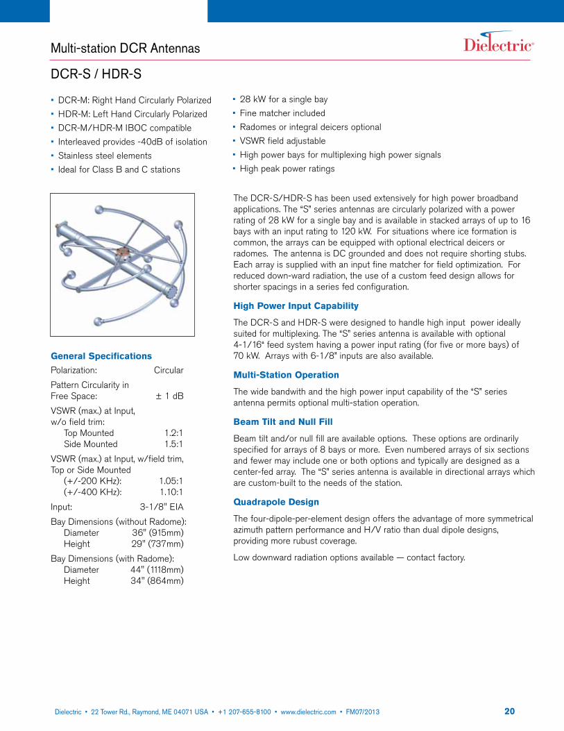
The DCR-S/HDR-S has been used extensively for high power broadband applications. The “S” series antennas are circularly polarized with a power rating of 28 kW for a single bay and is available in stacked arrays of up to 16 bays with an input rating to 120 kW. For situations where ice formation is common, the arrays can be equipped with optional electrical deicers or radomes. The antenna is DC grounded and does not require shorting stubs. Each array is supplied with an input fine matcher for field optimization. For reduced down-ward radiation, the use of a custom feed design allows for shorter spacings in a series fed configuration.
High Power Input Capability
The DCR-S and HDR-S were designed to handle high input power ideally suited for multiplexing. The “S” series antenna is available with optional 4-1/16“ feed system having a power input rating (for five or more bays) of 70 kW. Arrays with 6-1/8” inputs are also available.
Multi-Station Operation
The wide bandwith and the high power input capability of the “S” series antenna permits optional multi-station operation.
Beam Tilt and Null Fill
Beam tilt and/or null fill are available options. These options are ordinarily specified for arrays of 8 bays or more. Even numbered arrays of six sections and fewer may include one or both options and typically are designed as a center-fed array. The “S” series antenna is available in directional arrays which are custom-built to the needs of the station.
quadrapole Design
The four-dipole-per-element design offers the advantage of more symmetrical azimuth pattern performance and H/V ratio than dual dipole designs, providing more rubust coverage.
Low downward radiation options available — contact factory.
• DCR-M: Right Hand Circularly Polarized• HDR-M: Left Hand Circularly Polarized• DCR-M/HDR-M IBOC compatible• Interleaved provides -40dB of isolation• Stainless steel elements• Ideal for Class B and C stations
Multi-station DCR Antennas
DCR-S / HDR-S
• 28 kW for a single bay• Fine matcher included• Radomes or integral deicers optional• VSWR field adjustable• High power bays for multiplexing high power signals• High peak power ratings
General SpecificationsPolarization: CircularPattern Circularity in Free Space: ± 1 dBVSWR (max.) at Input, w/o field trim: Top Mounted 1.2:1 Side Mounted 1.5:1 VSWR (max.) at Input, w/field trim, Top or Side Mounted (+/-200 KHz): 1.05:1 (+/-400 KHz): 1.10:1 Input: 3-1/8" EIABay Dimensions (without Radome): Diameter 36" (915mm) Height 29" (737mm)Bay Dimensions (with Radome): Diameter 44" (1118mm) Height 34" (864mm)
2122 Tower Road, P.O. Box 949, Raymond, ME 04071 • 207-655-8100 • 1-800-341-9678 • Fax: 207-655-8177 • www.dielectric.comDielectric • 22 Tower Rd., Raymond, ME 04071 USA • +1 207-655-8100 • www.dielectric.com • FM07/2013
Multi-station DCR Antennas
DCR-S / HDR-S
Notes:1. CaAc and weight includes bays and standard extension brackets for mounting. Excludes custom mounts.
For antennas that include pattern studies, contact factory for additional information.2. Dimensions are for antennas at 98.0 MHz and can vary ± 10% across the band.3. Ice shields are strongly recommended for areas subject to icing conditions. Dielectric is not responsible for antenna damage caused by
impact from falling ice.4. Calculated area (CaAc) expressed in TIA/EIA-222-F standard.5. Specs. are for a single DCR-S antenna array or HDR-S antenna array, not both.
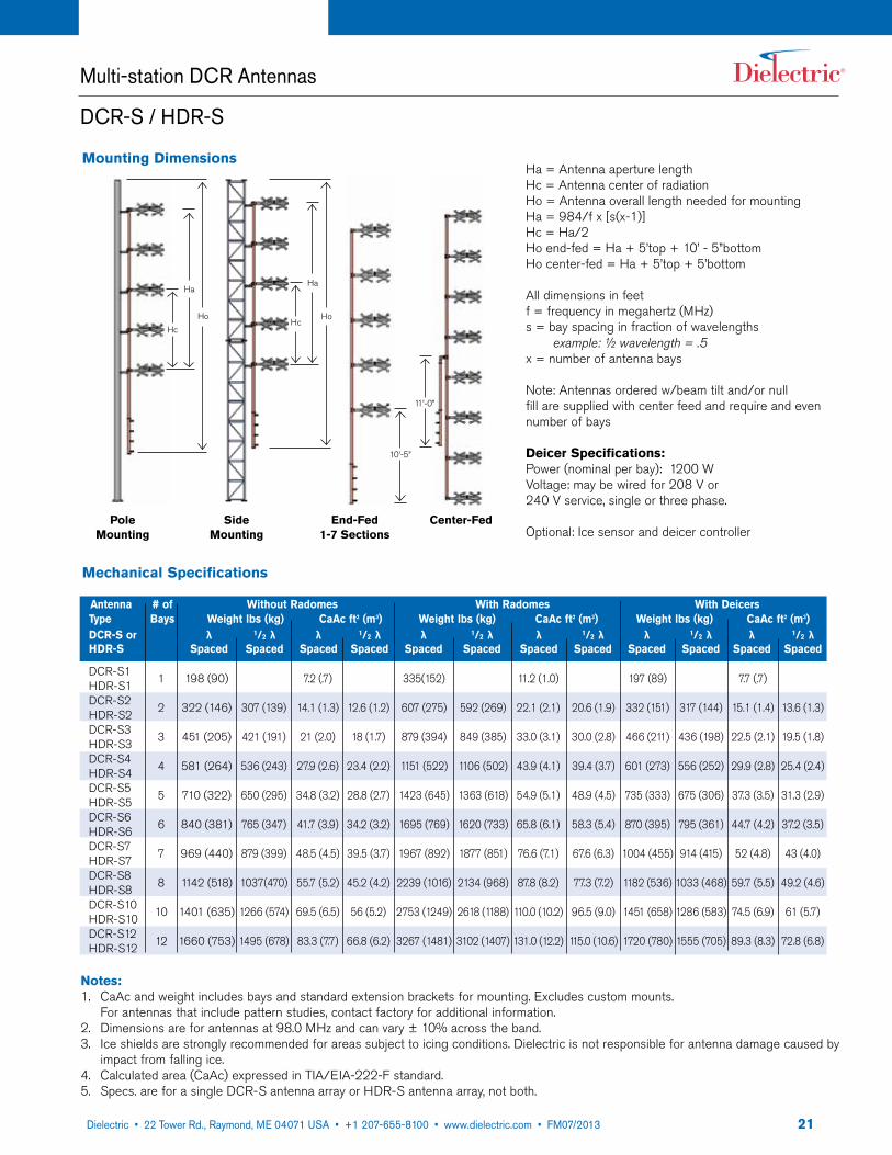
Mounting Dimensions
10’-5”
Hc
Ha
Ho
Pole Mounting
Side Mounting
End-Fed 1-7 Sections
Center-Fed
Hc
Ha
Ho
11’-0”
Ha = Antenna aperture lengthHc = Antenna center of radiationHo = Antenna overall length needed for mountingHa = 984/f x [s(x-1)]Hc = Ha/2Ho end-fed = Ha + 5’top + 10’ - 5”bottomHo center-fed = Ha + 5’top + 5’bottom
All dimensions in feetf = frequency in megahertz (MHz)s = bay spacing in fraction of wavelengths example: ½ wavelength = .5x = number of antenna bays
Note: Antennas ordered w/beam tilt and/or null fill are supplied with center feed and require and even number of bays
Deicer Specifications:Power (nominal per bay): 1200 WVoltage: may be wired for 208 V or240 V service, single or three phase.
Optional: Ice sensor and deicer controller
Mechanical Specifications
Antenna # of Without Radomes With Radomes With Deicers Type Bays Weight lbs (kg) CaAc ft2 (m3) Weight lbs (kg) CaAc ft2 (m3) Weight lbs (kg) CaAc ft2 (m3) DCR-S or λ 1/2 λ λ 1/2 λ λ 1/2 λ λ 1/2 λ λ 1/2 λ λ 1/2 λ HDR-S Spaced Spaced Spaced Spaced Spaced Spaced Spaced Spaced Spaced Spaced Spaced Spaced
DCR-S1HDR-S1DCR-S2HDR-S2DCR-S3HDR-S3DCR-S4HDR-S4DCR-S5HDR-S5DCR-S6HDR-S6DCR-S7HDR-S7DCR-S8HDR-S8DCR-S10HDR-S10DCR-S12HDR-S12
198 (90)
322 (146)
451 (205)
581 (264)
710 (322)
840 (381)
969 (440)
1142 (518)
1401 (635)
1660 (753)
307 (139)
421 (191)
536 (243)
650 (295)
765 (347)
879 (399)
1037(470)
1266 (574)
1495 (678)
7.2 (.7)
14.1 (1.3)
21 (2.0)
27.9 (2.6)
34.8 (3.2)
41.7 (3.9)
48.5 (4.5)
55.7 (5.2)
69.5 (6.5)
83.3 (7.7)
335(152)
607 (275)
879 (394)
1151 (522)
1423 (645)
1695 (769)
1967 (892)
2239 (1016)
2753 (1249)
3267 (1481)
12.6 (1.2)
18 (1.7)
23.4 (2.2)
28.8 (2.7)
34.2 (3.2)
39.5 (3.7)
45.2 (4.2)
56 (5.2)
66.8 (6.2)
1
2
3
4
5
6
7
8
10
12
592 (269)
849 (385)
1106 (502)
1363 (618)
1620 (733)
1877 (851)
2134 (968)
2618 (1188)
3102 (1407)
11.2 (1.0)
22.1 (2.1)
33.0 (3.1)
43.9 (4.1)
54.9 (5.1)
65.8 (6.1)
76.6 (7.1)
87.8 (8.2)
110.0 (10.2)
131.0 (12.2)
20.6 (1.9)
30.0 (2.8)
39.4 (3.7)
48.9 (4.5)
58.3 (5.4)
67.6 (6.3)
77.3 (7.2)
96.5 (9.0)
115.0 (10.6)
197 (89)
332 (151)
466 (211)
601 (273)
735 (333)
870 (395)
1004 (455)
1182 (536)
1451 (658)
1720 (780)
7.7 (.7)
15.1 (1.4)
22.5 (2.1)
29.9 (2.8)
37.3 (3.5)
44.7 (4.2)
52 (4.8)
59.7 (5.5)
74.5 (6.9)
89.3 (8.3)
317 (144)
436 (198)
556 (252)
675 (306)
795 (361)
914 (415)
1033 (468)
1286 (583)
1555 (705)
13.6 (1.3)
19.5 (1.8)
25.4 (2.4)
31.3 (2.9)
37.2 (3.5)
43 (4.0)
49.2 (4.6)
61 (5.7)
72.8 (6.8)

2222 Tower Road, P.O. Box 949, Raymond, ME 04071 • 207-655-8100 • 1-800-341-9678 • Fax: 207-655-8177 • www.dielectric.comDielectric • 22 Tower Rd., Raymond, ME 04071 USA • +1 207-655-8100 • www.dielectric.com • FM07/2013
Notes:1. RMS gain data is given relative to dipole. Values are for midband and include standard harness configurations.
Actual gain will vary depending on feed system, frequency, null fill, and beam tilt.2. Average power ratings are nominal @ 40˚C (104˚F) ambient. Assumes constant pressurization with dry air or
nitrogen. Ratings may vary based on specific feed system design and local conditions.3. Higher power ratings and custom feed systems may be available on request.4. Antenna components and feed harnesses are optimized for FM channels of interest5. Specifications. are for a single DCR-S antenna array or HDR-S antenna array, not both.
Electrical Specifications
Antenna Type Gain Polarization spacing1 Power DCR-S or HDR-S λ Spacing 1/2 λ Spacing Rating kW3
Power Gain dB Power Gain dB
DCR-S1HDR-S1DCR-S2HDR-S2DCR-S3HDR-S3DCR-S4HDR-S4DCR-S5HDR-S5DCR-S6HDR-S6DCR-S7HDR-S7DCR-S8HDR-S8DCR-S10HDR-S10DCR-S12HDR-S12
0.46
1.0
1.5
2.1
2.7
3.2
3.8
4.3
5.5
6.6
-3.37
0
1.76
3.22
4.31
5.05
5.80
6.34
7.40
8.2
0.7
1.0
1.3
1.6
1.8
2.1
2.3
2.9
3.5
28
40
40
40
40
40
40
40
40
40
-1.55
0
1.14
1.76
2.55
3.22
3.62
4.62
5.44
Multi-station DCR Antennas
DCR-S / HDR-S
2322 Tower Road, P.O. Box 949, Raymond, ME 04071 • 207-655-8100 • 1-800-341-9678 • Fax: 207-655-8177 • www.dielectric.comDielectric • 22 Tower Rd., Raymond, ME 04071 USA • +1 207-655-8100 • www.dielectric.com • FM07/2013
Multi-station DCR Antennas
DCR-MFE "Funky Elbow"
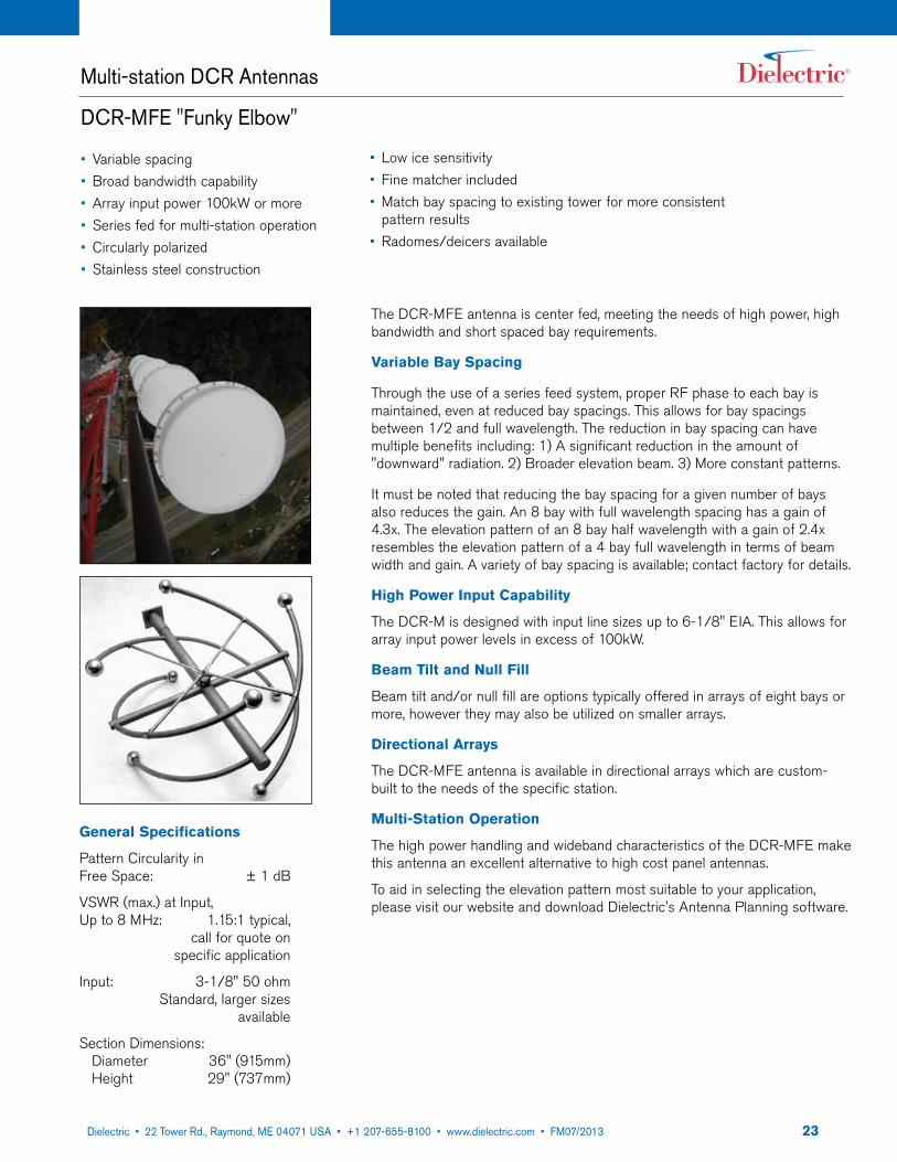
The DCR-MFE antenna is center fed, meeting the needs of high power, high bandwidth and short spaced bay requirements.
Variable Bay Spacing
Through the use of a series feed system, proper RF phase to each bay is maintained, even at reduced bay spacings. This allows for bay spacings between 1/2 and full wavelength. The reduction in bay spacing can have multiple benefits including: 1) A significant reduction in the amount of "downward" radiation. 2) Broader elevation beam. 3) More constant patterns.
It must be noted that reducing the bay spacing for a given number of bays also reduces the gain. An 8 bay with full wavelength spacing has a gain of 4.3x. The elevation pattern of an 8 bay half wavelength with a gain of 2.4x resembles the elevation pattern of a 4 bay full wavelength in terms of beam width and gain. A variety of bay spacing is available; contact factory for details.
High Power Input Capability
The DCR-M is designed with input line sizes up to 6-1/8" EIA. This allows for array input power levels in excess of 100kW.
Beam Tilt and Null Fill
Beam tilt and/or null fill are options typically offered in arrays of eight bays or more, however they may also be utilized on smaller arrays.
Directional Arrays
The DCR-MFE antenna is available in directional arrays which are custom-built to the needs of the specific station.
Multi-Station Operation
The high power handling and wideband characteristics of the DCR-MFE make this antenna an excellent alternative to high cost panel antennas.
To aid in selecting the elevation pattern most suitable to your application, please visit our website and download Dielectric's Antenna Planning software.
• Variable spacing• Broad bandwidth capability• Array input power 100kW or more• Series fed for multi-station operation• Circularly polarized• Stainless steel construction
• Low ice sensitivity• Fine matcher included• Match bay spacing to existing tower for more consistent
pattern results• Radomes/deicers available
General Specifications
Pattern Circularity in Free Space: ± 1 dB
VSWR (max.) at Input, Up to 8 MHz: 1.15:1 typical, call for quote on specific application
Input: 3-1/8" 50 ohm Standard, larger sizes available
Section Dimensions: Diameter 36" (915mm) Height 29" (737mm)

2422 Tower Road, P.O. Box 949, Raymond, ME 04071 • 207-655-8100 • 1-800-341-9678 • Fax: 207-655-8177 • www.dielectric.comDielectric • 22 Tower Rd., Raymond, ME 04071 USA • +1 207-655-8100 • www.dielectric.com • FM07/2013
Multi-station DCR Antennas
DCR-MFE "Funky Elbow"
Notes:1. RMS gain data is given relative to dipole. Values are for each polarizatiion and nominal
for midband and include standard harness configurations. Actual gain will vary depending on feed system, frequency, null fill, and beam tilt.
2. Average power ratings are nominal @ 40˚C ambient. Assumes constant pressurization with dry air or nitrogen. Ratings may vary based on specific feed system design and local conditions.
3. Higher power ratings and custom feed systems may be available on request.4. Antenna components and feed harnesses are optimized for FM channels of interest.
Electrical Specifications
Gain Polarization spacing1 Power Antenna 3/4 λ Spacing 7/8 λ Spacing Rating kW3
Type Power Gain dB Power Gain dB
DCR-MFE4
DCR-MFE6
DCR-MFE8
DCR-MFE10
DCR-MFE12
1.80
2.70
3.60
4.50
5.40
2.55
4.31
5.56
6.53
7.32
2.1
3.1
4.1
5.1
6.1
40
40
40
40
40
3.22
4.91
6.12
7.08
7.85
Notes:1. Weights include bays and standard extension brackets for mounting. Excludes feed system and custom mounts. For
antennas that included pattern studies, contact factory for additional information.2. Projected area includes bays and standard extension brackets. Excludes feed system and custom mounts.3. Dimensions are for antennas at 98.0 MHz and can vary ±10% across the band.4. Ice shields are strongly recommended for areas subject to tower icing. Dielectric is not responsible for antenna damage
caused by impact from falling ice.5. Area calculated expressed in terms of equivalent flats (RS-222-C-standard).6. Windload force calculated based on 50 pounds per square foot (50psf) on flats (RS-222-C-standard).7. To convert area to equivalent rounds, multiply area by 1.5.8. To convert area to Aerodynamic area (CaAa - linear or CaAc - discrete) based on EIA-222-F standard, multiply area by 1.8.
Deicer Specifications:Power (nominal, per bay): 1200 WVoltage: May be wired for 208V or 240V service, single- or three-phase
Optional: Ice sensor and deicer controller.
Mechanical Specifications
Antenna # of Without Radomes With Radomes With Deicers Type Bays Weight lbs (kg) CaAc ft2 (m2) Weight lbs (kg) CaAc ft2 (m2) Weight lbs (kg) CaAc ft2 (m2) DCR-M or 3/4 λ 7/8 λ 3/4 λ 7/8 λ 3/4 λ 7/8 λ 3/4 λ 7/8 λ 3/4 λ 7/8 λ 3/4 λ 7/8 λ HDR-M Spaced Spaced Spaced Spaced Spaced Spaced Spaced Spaced Spaced Spaced Spaced Spaced
DCR-M2HDR-M2DCR-M3HDR-M3DCR-M4HDR-M4DCR-M5HDR-M5DCR-M6HDR-M6DCR-M7HDR-M7DCR-M8HDR-M8DCR-M10HDR-M10DCR-M12HDR-M12
277 (126)
384 (175)
492 (224)
600 (273)
707 (321)
814 (370)
965 (439)
1180 (536)
1395 (634)
280 (127)
391 (178)
502 (228)
613 (279)
724 (329)
835 (380)
989 (450)
1211 (550)
1433 (651)
12.1 (1.1)
17.6 (1.6)
23.1 (2.1)
28.6 (2.7)
34.2 (3.2)
39.6 (3.7)
45.4 (4.2)
56.4 (5.2)
67.4 (6.3)
562 (255)
812 (369)
1062 (483)
1412 (642)
1562 (710)
1812 (823)
2062 (937)
2532 (1151)
3002 (1364)
12.5 (1.2)
18.4 (1.7)
24.3 (2.3)
30.2 (2.8)
36.2 (3.4)
42.0 (3.9)
48.2 (4.5)
60.0 (5.6)
71.8 (6.7)
2
3
4
5
6
7
8
10
12
565 (257)
819 (372)
1072 (487)
1426 (648)
1579 (718)
1833 (833)
2086 (948)
2563 (1165)
3040 (1382)
21.3 (2.0)
31.4 (2.9)
41.5 (3.9)
51.7 (4.8)
61.9 (5.7)
71.9 (6.7)
82.3 (7.6)
102.9 (9.6)
122.3 (11.4)
21.7 (2.0)
32.2 (3.0)
42.7 (4.0)
53.3 (5.0)
63.9 (5.9)
74.3 (6.9)
85.1 (7.9)
106.5 (9.9)
126.7 (11.8)
287 (130)
399 (181)
512 (233)
624 (283)
737 (335)
849 (386)
1005 (457)
1230 (559)
1455 (661)
13.1 (1.2)
19.1 (1.8)
25.1 (2.3)
31.1 (2.9)
37.2 (3.5)
43.1 (4.0)
49.4 (4.6)
61.4 (5.7)
73.4 (6.8)
290 (132)
406 (184)
522 (237)
638 (290)
754 (343)
870 (395)
1029 (468)
1260 (573)
1493 (679)
13.5 (1.3)
19.9 (1.9)
26.3 (2.4)
32.7 (3.0)
39.2 (3.6)
45.5 (4.2)
52.2 (4.8)
65.0 (6.0)
77.8 (7.2)
2522 Tower Road, P.O. Box 949, Raymond, ME 04071 • 207-655-8100 • 1-800-341-9678 • Fax: 207-655-8177 • www.dielectric.comDielectric • 22 Tower Rd., Raymond, ME 04071 USA • +1 207-655-8100 • www.dielectric.com • FM07/2013
Multi-station DCR Antennas
DCR-M / HDR-M
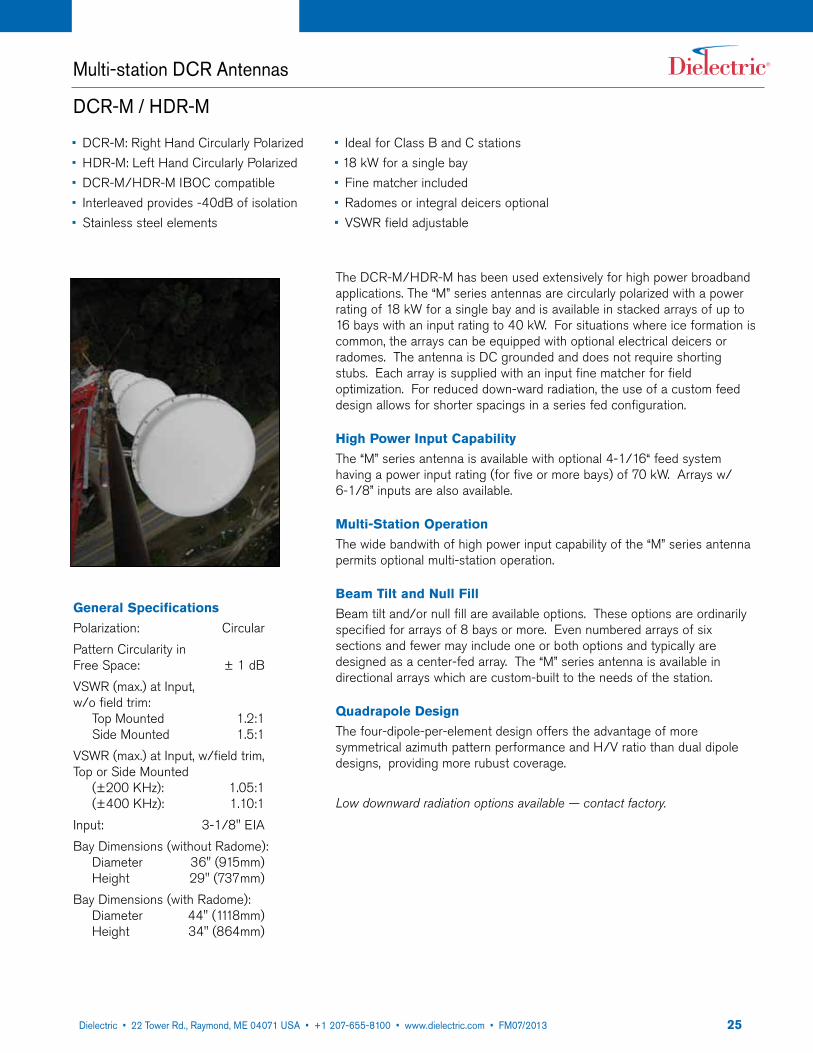
The DCR-M/HDR-M has been used extensively for high power broadband applications. The “M” series antennas are circularly polarized with a power rating of 18 kW for a single bay and is available in stacked arrays of up to 16 bays with an input rating to 40 kW. For situations where ice formation is common, the arrays can be equipped with optional electrical deicers or radomes. The antenna is DC grounded and does not require shorting stubs. Each array is supplied with an input fine matcher for field optimization. For reduced down-ward radiation, the use of a custom feed design allows for shorter spacings in a series fed configuration.
High Power Input CapabilityThe “M” series antenna is available with optional 4-1/16“ feed system having a power input rating (for five or more bays) of 70 kW. Arrays w/ 6-1/8” inputs are also available.
Multi-Station OperationThe wide bandwith of high power input capability of the “M” series antenna permits optional multi-station operation.
Beam Tilt and Null FillBeam tilt and/or null fill are available options. These options are ordinarily specified for arrays of 8 bays or more. Even numbered arrays of six sections and fewer may include one or both options and typically are designed as a center-fed array. The “M” series antenna is available in directional arrays which are custom-built to the needs of the station.
quadrapole DesignThe four-dipole-per-element design offers the advantage of more symmetrical azimuth pattern performance and H/V ratio than dual dipole designs, providing more rubust coverage.
Low downward radiation options available — contact factory.
General SpecificationsPolarization: CircularPattern Circularity in Free Space: ± 1 dBVSWR (max.) at Input, w/o field trim: Top Mounted 1.2:1 Side Mounted 1.5:1 VSWR (max.) at Input, w/field trim, Top or Side Mounted (±200 KHz): 1.05:1 (±400 KHz): 1.10:1 Input: 3-1/8" EIABay Dimensions (without Radome): Diameter 36" (915mm) Height 29" (737mm)Bay Dimensions (with Radome): Diameter 44" (1118mm) Height 34" (864mm)
• DCR-M: Right Hand Circularly Polarized• HDR-M: Left Hand Circularly Polarized• DCR-M/HDR-M IBOC compatible• Interleaved provides -40dB of isolation• Stainless steel elements
• Ideal for Class B and C stations• 18 kW for a single bay• Fine matcher included• Radomes or integral deicers optional• VSWR field adjustable
2622 Tower Road, P.O. Box 949, Raymond, ME 04071 • 207-655-8100 • 1-800-341-9678 • Fax: 207-655-8177 • www.dielectric.comDielectric • 22 Tower Rd., Raymond, ME 04071 USA • +1 207-655-8100 • www.dielectric.com • FM07/2013
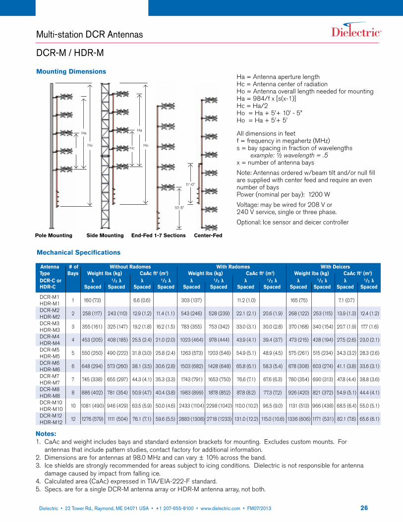
Mounting Dimensions
Multi-station DCR Antennas
DCR-M / HDR-M
Notes:1. CaAc and weight includes bays and standard extension brackets for mounting. Excludes custom mounts. For
antennas that include pattern studies, contact factory for additional information.2. Dimensions are for antennas at 98.0 MHz and can vary ± 10% across the band.3. Ice shields are strongly recommended for areas subject to icing conditions. Dielectric is not responsible for antenna
damage caused by impact from falling ice.4. Calculated area (CaAc) expressed in TIA/EIA-222-F standard.5. Specs. are for a single DCR-M antenna array or HDR-M antenna array, not both.
Ha = Antenna aperture lengthHc = Antenna center of radiationHo = Antenna overall length needed for mountingHa = 984/f x [s(x-1)]Hc = Ha/2Ho = Ha + 5’+ 10’ - 5”Ho = Ha + 5’+ 5’
All dimensions in feetf = frequency in megahertz (MHz)s = bay spacing in fraction of wavelengths example: ½ wavelength = .5x = number of antenna baysNote: Antennas ordered w/beam tilt and/or null fill are supplied with center feed and require an even number of baysPower (nominal per bay): 1200 WVoltage: may be wired for 208 V or240 V service, single or three phase.Optional: Ice sensor and deicer controller
10’-5”
Hc
Ha
Ho
Pole Mounting Side Mounting End-Fed 1-7 Sections Center-Fed
Ha
Ho
11’-0”
Mechanical Specifications
Antenna # of Without Radomes With Radomes With Deicers Type Bays Weight lbs (kg) CaAc ft2 (m3) Weight lbs (kg) CaAc ft2 (m3) Weight lbs (kg) CaAc ft2 (m3) DCR-C or λ 1/2 λ λ 1/2 λ λ 1/2 λ λ 1/2 λ λ 1/2 λ λ 1/2 λ HDR-C Spaced Spaced Spaced Spaced Spaced Spaced Spaced Spaced Spaced Spaced Spaced Spaced
DCR-M1HDR-M1DCR-M2HDR-M2DCR-M3HDR-M3DCR-M4HDR-M4DCR-M5HDR-M5DCR-M6HDR-M6DCR-M7HDR-M7DCR-M8HDR-M8DCR-M10HDR-M10DCR-M12HDR-M12
160 (73)
258 (117)
355 (161)
453 (205)
550 (250)
648 (294)
745 (338)
886 (402)
1081 (490)
1276 (579)
243 (110)
325 (147)
408 (185)
490 (222)
573 (260)
655 (297)
781 (354)
946 (429)
1111 (504)
6.6 (0.6)
12.9 (1.2)
19.2 (1.8)
25.5 (2.4)
31.8 (3.0)
38.1 (3.5)
44.3 (4.1)
50.9 (4.7)
63.5 (5.9)
76.1 (7.1)
303 (137)
543 (246)
783 (355)
1023 (464)
1263 (573)
1503 (682)
1743 (791)
1983 (899)
2433 (1104)
2883 (1308)
11.4 (1.1)
16.2 (1.5)
21.0 (2.0)
25.8 (2.4)
30.6 (2.8)
35.3 (3.3)
40.4 (3.8)
50.0 (4.6)
59.6 (5.5)
1
2
3
4
5
6
7
8
10
12
528 (239)
753 (342)
978 (444)
1203 (546)
1428 (648)
1653 (750)
1878 (852)
2298 (1042)
2718 (1233)
11.2 (1.0)
22.1 (2.1)
33.0 (3.1)
43.9 (4.1)
54.9 (5.1)
65.8 (6.1)
76.6 (7.1)
87.8 (8.2)
110.0 (10.2)
131.0 (12.2)
20.6 (1.9)
30.0 (2.8)
39.4 (3.7)
48.9 (4.5)
58.3 (5.4)
67.6 (6.3)
77.3 (7.2)
96.5 (9.0)
115.0 (10.6)
165 (75)
268 (122)
370 (168)
473 (215)
575 (261)
678 (308)
780 (354)
926 (420)
1131 (513)
1336 (606)
7.1 (0.7)
13.9 (1.3)
20.7 (1.9)
27.5 (2.6)
34.3 (3.2)
41.1 (3.8)
47.8 (4.4)
54.9 (5.1)
68.5 (6.4)
82.1 (7.6)
253 (115)
340 (154)
428 (194)
515 (234)
603 (274)
690 (313)
821 (372)
966 (438)
1171 (531)
12.4 (1.2)
17.7 (1.6)
23.0 (2.1)
28.3 (2.6)
33.6 (3.1)
38.8 (3.6)
44.4 (4.1)
55.0 (5.1)
65.6 (6.1)

2722 Tower Road, P.O. Box 949, Raymond, ME 04071 • 207-655-8100 • 1-800-341-9678 • Fax: 207-655-8177 • www.dielectric.comDielectric • 22 Tower Rd., Raymond, ME 04071 USA • +1 207-655-8100 • www.dielectric.com • FM07/2013
Notes:1. RMS gain data is given relative to dipole. Values are for midband and include standard harness configurations.
Actual gain will vay depending on feed system, frequency, null fill, and beam tilt.2. Average power ratings are nominal @ 40°C ambient. Assumes constant pressurization with dry air or nitrogen.
Ratings may vary based on specific feed system design and local conditions.3. Higher power ratings and custom feed systems may be available on request.4. Antenna components and feed harnesses are optimized for FM channels of interest5. Specs. are for a single DCR-M antenna array or HDR-M antenna array, not both.
Electrical Specifications
Antenna Type Gain Polarization spacing1 Power DCR-M or HDR-M λ Spacing 1/2 λ Spacing Rating kW3
Power Gain dB Power Gain dB
DCR-M1HDR-M1DCR-M2HDR-M2DCR-M3HDR-M3DCR-M4HDR-M4DCR-M5HDR-M5DCR-M6HDR-M6DCR-M7HDR-M7DCR-M8HDR-M8DCR-M10HDR-M10DCR-M12HDR-M12
0.46
1.0
1.5
2.1
2.7
3.2
3.8
4.3
5.5
6.6
-3.37
0
1.76
3.22
4.31
5.05
5.80
6.34
7.40
8.2
0.7
1.0
1.3
1.6
1.8
2.1
2.3
2.9
3.5
18
36
40
40
40
40
40
40
40
40
-1.55
0
1.14
1.76
2.55
3.22
3.62
4.62
5.44
Multi-station DCR Antennas
DCR-M / HDR-M
2822 Tower Road, P.O. Box 949, Raymond, ME 04071 • 207-655-8100 • 1-800-341-9678 • Fax: 207-655-8177 • www.dielectric.comDielectric • 22 Tower Rd., Raymond, ME 04071 USA • +1 207-655-8100 • www.dielectric.com • FM07/2013
Multi-station DCR Antennas
DCR-MT Series Quadrapole Antenna
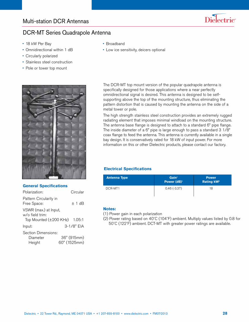
The DCR-MT top mount version of the popular quadrapole antenna is specifically designed for those applications where a near perfectly omnidirectional signal is desired. This antenna is designed to be self-supporting above the top of the mounting structure, thus eliminating the pattern distortion that is caused by mounting the antenna on the side of a metal tower or pole.The high strength stainless steel construction provides an extremely rugged radiating element that imposes minimal windload on the mounting structure. The antenna base flange is designed to attach to a standard 6” pipe flange. The inside diameter of a 6” pipe is large enough to pass a standard 3 1/8” coax flange to feed the antenna. This antenna is currently available in a single bay design. It is conservatively rated for 18 kW of input power. For more information on this or other Dielectric products, please contact our factory.
General SpecificationsPolarization: CircularPattern Circularity in Free Space: ± 1 dBVSWR (max.) at Input, w/o field trim: Top Mounted (±200 KHz) 1.05:1 Input: 3-1/8" EIASection Dimensions: Diameter 36" (915mm) Height 60" (1525mm)
• 18 kW Per Bay• Omnidirectional within 1 dB• Circularly polarized• Stainless steel construction• Pole or tower top mount
• Broadband• Low ice sensitivity, deicers optional
Electrical Specifications
Antenna Type Gain1 Power Power (dB)1 Rating kW2
DCR-MT1 0.46 (-3.37) 18
Notes:(1) Power gain in each polarization(2) Power rating based on 40˚C (104˚F) ambient. Multiply values listed by 0.8 for
50˚C (122˚F) ambient. DCT-MT with greater power ratings are available.
2922 Tower Road, P.O. Box 949, Raymond, ME 04071 • 207-655-8100 • 1-800-341-9678 • Fax: 207-655-8177 • www.dielectric.comDielectric • 22 Tower Rd., Raymond, ME 04071 USA • +1 207-655-8100 • www.dielectric.com • FM07/2013
Notes:(1) Power gain in each polarization(2) Power rating based on 40˚C (104˚F) ambient. Multiply values listed by 0.8 for
50˚C (122˚F) ambient. DCT-MT with greater power ratings are available.
DCR Antennas
DCR-C / HDR-C
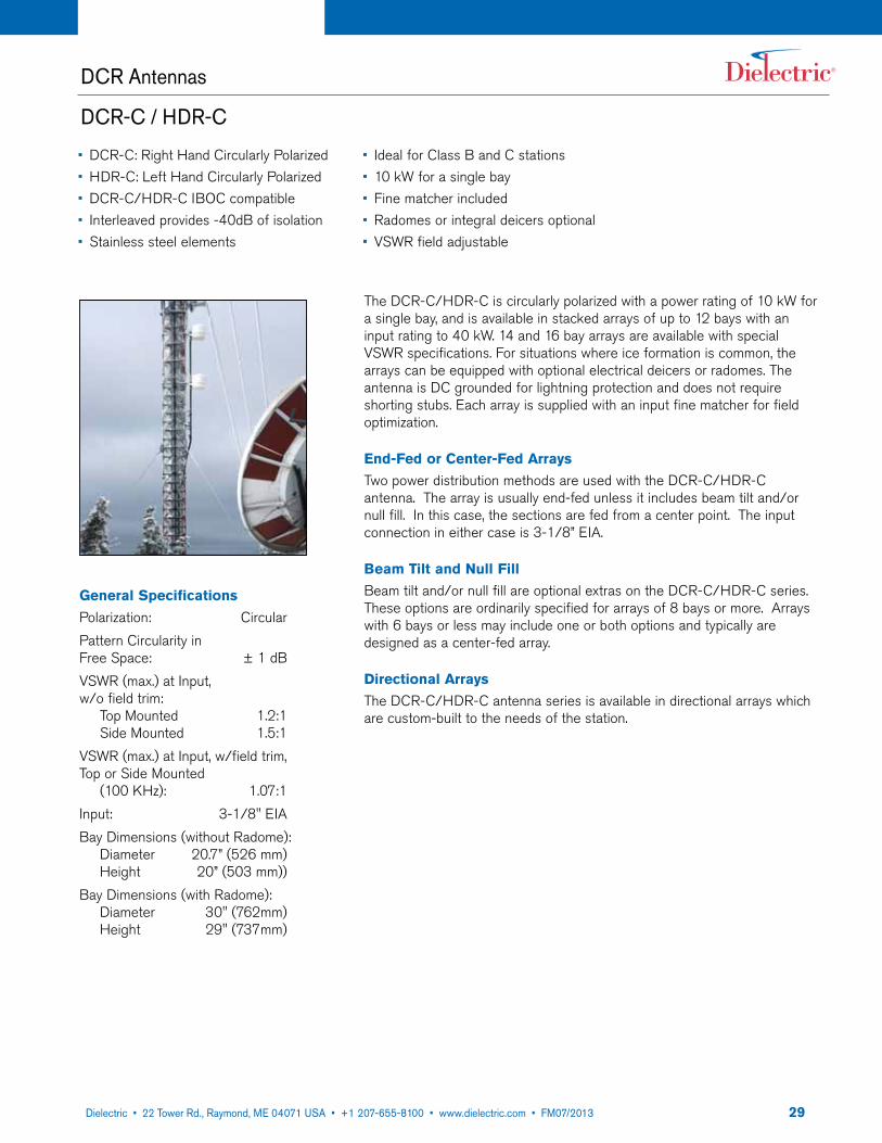
The DCR-C/HDR-C is circularly polarized with a power rating of 10 kW for a single bay, and is available in stacked arrays of up to 12 bays with an input rating to 40 kW. 14 and 16 bay arrays are available with special VSWR specifications. For situations where ice formation is common, the arrays can be equipped with optional electrical deicers or radomes. The antenna is DC grounded for lightning protection and does not require shorting stubs. Each array is supplied with an input fine matcher for field optimization.
End-Fed or Center-Fed ArraysTwo power distribution methods are used with the DCR-C/HDR-C antenna. The array is usually end-fed unless it includes beam tilt and/or null fill. In this case, the sections are fed from a center point. The input connection in either case is 3-1/8” EIA.
Beam Tilt and Null FillBeam tilt and/or null fill are optional extras on the DCR-C/HDR-C series. These options are ordinarily specified for arrays of 8 bays or more. Arrays with 6 bays or less may include one or both options and typically are designed as a center-fed array.
Directional ArraysThe DCR-C/HDR-C antenna series is available in directional arrays which are custom-built to the needs of the station.
General SpecificationsPolarization: CircularPattern Circularity in Free Space: ± 1 dBVSWR (max.) at Input, w/o field trim: Top Mounted 1.2:1 Side Mounted 1.5:1 VSWR (max.) at Input, w/field trim, Top or Side Mounted (100 KHz): 1.07:1Input: 3-1/8" EIABay Dimensions (without Radome): Diameter 20.7” (526 mm) Height 20” (503 mm))Bay Dimensions (with Radome): Diameter 30" (762mm) Height 29" (737mm)
• DCR-C: Right Hand Circularly Polarized• HDR-C: Left Hand Circularly Polarized• DCR-C/HDR-C IBOC compatible• Interleaved provides -40dB of isolation• Stainless steel elements
• Ideal for Class B and C stations• 10 kW for a single bay• Fine matcher included• Radomes or integral deicers optional• VSWR field adjustable
3022 Tower Road, P.O. Box 949, Raymond, ME 04071 • 207-655-8100 • 1-800-341-9678 • Fax: 207-655-8177 • www.dielectric.comDielectric • 22 Tower Rd., Raymond, ME 04071 USA • +1 207-655-8100 • www.dielectric.com • FM07/2013
DCR Antennas
DCR-C / HDR-C
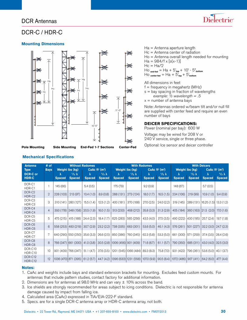
Ha = Antenna aperture lengthHc = Antenna center of radiationHo = Antenna overall length needed for mountingHa = 984/f x [s(x-1)]Hc = Ha/2Ho end-fed = Ha + 5’top + 10’ - 5”bottom
Ho center-fed = Ha + 5’top + 5’bottom
All dimensions in feetf = frequency in megahertz (MHz)s = bay spacing in fraction of wavelengths example: ½ wavelength = .5x = number of antenna baysNote: Antennas ordered w/beam tilt and/or null fill are supplied with center feed and require an even number of bays
DEICER SPECIFICATIONS:Power (nominal per bay): 600 WVoltage: may be wired for 208 V or240 V service, single or three phase.Optional: Ice sensor and deicer controller
Mounting Dimensions
11’-0”
Hc
Ha
HoHc
Ha
Ho
10’-5”
Pole Mounting Side Mounting End-Fed 1-7 Sections Center-Fed
Notes:1. CaAc and weights include bays and standard extension brackets for mounting. Excludes feed custom mounts. For
antennas that include pattern studies, contact factory for additional information.2. Dimensions are for antennas at 98.0 MHz and can vary ± 10% across the band.3. Ice shields are strongly recommended for areas subject to icing conditions. Dielectric is not responsible for antenna
damage caused by impact from falling ice.4. Calculated area (CaAc) expressed in TIA/EIA-222-F standard.5. Specs. are for a single DCR-C antenna array or HDR-C antenna array, not both.
Mechanical Specifications
Antenna # of Without Radomes With Radomes With Deicers Type Bays Weight lbs (kg) CaAc ft2 (m3) Weight lbs (kg) CaAc ft2 (m3) Weight lbs (kg) CaAc ft2 (m3) DCR-C or λ 1/2 λ λ 1/2 λ λ 1/2 λ λ 1/2 λ λ 1/2 λ λ 1/2 λ HDR-C Spaced Spaced Spaced Spaced Spaced Spaced Spaced Spaced Spaced Spaced Spaced Spaced
DCR-C1HDR-C1DCR-C2HDR-C2DCR-C3HDR-C3DCR-C4HDR-C4DCR-C5HDR-C5DCR-C6HDR-C6DCR-C7HDR-C7DCR-C8HDR-C8DCR-C10HDR-C10DCR-C12HDR-C12
145 (66)
228 (103)
310 (141)
393 (178)
475 (215)
558 (253)
640 (290)
766 (347)
901 (409)
1036 (470)
213 (97)
280 (127)
348 (158)
415 (188)
483 (219)
550 (250)
661 (300)
766 (347)
871 (395)
5.4 (0.5)
10.4 (1.0)
15.5 (1.4)
20.5 (1.9)
24.4 (2.3)
30.7 (2.9)
35.6 (3.3)
41.0 (3.8)
51.1 (4.7)
61.2 (5.7)
175 (79)
288 (131)
400 (181)
513 (233)
625 (283)
738 (335)
850 (386)
1006 (456)
1201 (545)
1396 (633)
8.9 (0.8)
12.5 (1.2)
16.0 (1.5)
18.4 (1.7)
23.2 (2.2)
26.6 (2.5)
30.5 (2.8)
37.6 (3.5)
44.7 (4.2)
1
2
3
4
5
6
7
8
10
12
273 (124)
370 (168)
468 (212)
565 (256)
663 (301)
760 (345)
901 (409)
1066 (484)
1231 (558)
9.2 (0.9)
18.0 (1.7)
27.0 (2.5)
35.8 (3.3)
43.5 (4.0)
53.6 (5.0)
62.3 (5.8)
71.6 (6.7)
89.3 (8.3)
107.0 (9.9)
16.5 (1.5)
24.0 (2.2)
31.3 (2.9)
37.5 (3.5)
46.1 (4.3)
53.3 (5.0)
61.1 (5.7)
75.8 (7.0)
90.5 (8.4)
148 (67)
234 (106)
319 (145)
405 (184)
490 (222)
576 (261)
661 (300)
790 (350)
931 (422)
1072 (486)
5.7 (0.5)
10.9 (1.0)
16.25 (1.5)
21.5 (2.0)
25.7 (2.4)
32.2 (3.0)
37.4 (3.5)
43.0 (4.0)
53.6 (5.0)
64.2 (6.0)
219 (99)
289 (131)
360 (163)
430 (195)
501 (227)
571 (259)
685 (311)
796 (361)
907 (411)
9.4 (0.9)
13.3 (1.2)
17.0 (1.6)
19.7 (1.8)
24.7 (2.3)
28.4 (2.6)
32.5 (3.0)
40.1 (3.7)
47.7 (4.4)

3122 Tower Road, P.O. Box 949, Raymond, ME 04071 • 207-655-8100 • 1-800-341-9678 • Fax: 207-655-8177 • www.dielectric.comDielectric • 22 Tower Rd., Raymond, ME 04071 USA • +1 207-655-8100 • www.dielectric.com • FM07/2013
Notes:1. RMS gain data is given relative to dipole. Values are for midband and include standard harness configurations. Actual
gain will vary depending on feed system, frequency, null fill, and beam tilt.2. Average power ratings are nominal @ 40˚C ambient. Assumes constant pressurization with dry air or nitrogen.
Ratings may vary based on specific feed system design and local conditions.3. Higher power ratings and custom feed systems may be available on request.4. Antenna components and feed harnesses are optimized for FM channels of interest.5. Specs. are for a single DCR-C antenna array or HDR-C antenna array, not both.
Electrical Specifications
Antenna Type Gain Polarization spacing Power DCR-C or HDR-C λ Spacing 1/2 λ Spacing Rating kW3
Power Gain dB Power Gain dB
DCR-C1HDR-C1DCR-C2HDR-C2DCR-C3HDR-C3DCR-C4HDR-C4DCR-C5HDR-C5DCR-C6HDR-C6DCR-C7HDR-C7DCR-C8HDR-C8DCR-C10HDR-C10DCR-C12HDR-C12
0.46
1.0
1.5
2.1
2.7
3.2
3.8
4.3
5.5
6.6
-3.37
0
1.76
3.22
4.31
5.05
5.80
6.34
7.40
8.2
0.7
1.0
1.3
1.6
1.8
2.1
2.4
3.1
3.7
10
20
30
40
40
40
40
40
40
40
-1.55
0
1.14
2.04
2.55
3.22
3.8
4.91
5.68
DCR Antennas
DCR-C / HDR-C

3222 Tower Road, P.O. Box 949, Raymond, ME 04071 • 207-655-8100 • 1-800-341-9678 • Fax: 207-655-8177 • www.dielectric.comDielectric • 22 Tower Rd., Raymond, ME 04071 USA • +1 207-655-8100 • www.dielectric.com • FM07/2013
DCR Antennas
DCR-H / HDR-H
The DCR-H/HDR-H antenna is a low-power version of the DCR-C/HDR-C and is available in one through twelve bays with an input power rating up to 12 kW. Each array is supplied with an input fine matcher for field optimization. For situations where ice formation is common, the arrays can be equipped with optional electrical deicers or radomes. The antenna is DC grounded for lightning protection and does not require shorting stubs. Each array is supplied with an input fine matcher for field optimization.
End-Fed or Center-Fed ArraysTwo power distribution methods are used with the DCR-H/HDR-H antenna. The array is usually end-fed unless it includes beam tilt and/or null fill. In this case, the sections are fed from a center point. The input connection in either case is 1-5/8” EIA.
Beam Tilt and Null FillBeam tilt and/or null fill are optional extras on the DCR-H/HDR-H series. If optional beam tilt or null fill is specified, the antenna is designed as a center-fed array.
Directional ArraysThe DCR-H/HDR-H antenna is available in directional arrays which are custom-built to the needs of the station.
Low downward radiation options available — contact factory.
General SpecificationsPolarization: CircularPattern Circularity in Free Space: ± 1 dBVSWR (max.) at Input, w/o field trim: Top Mounted 1.2:1 Side Mounted 1.5:1 VSWR (max.) at Input, w/field trim, Top or Side Mounted (±100 KHz): 1.07:1Input: 1-5/8" EIABay Dimensions (without Radome): Diameter 20.7” (526 mm) Height 20” (503 mm))
• DCR-H: Right Hand Circularly Polarized• HDR-H: Left Hand Circularly Polarized• DCR-H/HDR-H IBOC compatible• Interleaved provides >-40dB of isolation• Stainless steel elements• Ideal for Class A and B stations
• 4 kW for a single bay• Fine matcher included• Radomes or integral deicers optional• VSWR field adjustable• No circulators required
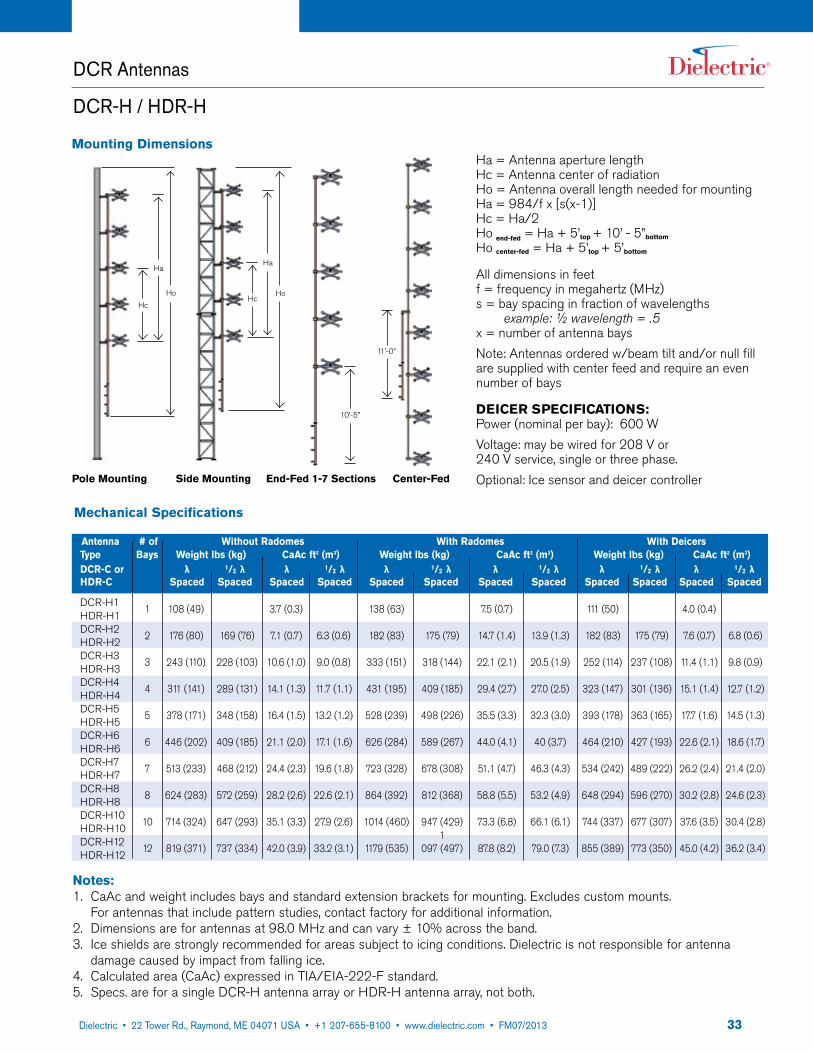
3322 Tower Road, P.O. Box 949, Raymond, ME 04071 • 207-655-8100 • 1-800-341-9678 • Fax: 207-655-8177 • www.dielectric.comDielectric • 22 Tower Rd., Raymond, ME 04071 USA • +1 207-655-8100 • www.dielectric.com • FM07/2013
Ha = Antenna aperture lengthHc = Antenna center of radiationHo = Antenna overall length needed for mountingHa = 984/f x [s(x-1)]Hc = Ha/2Ho end-fed = Ha + 5’top + 10’ - 5”bottom
Ho center-fed = Ha + 5’top + 5’bottom
All dimensions in feetf = frequency in megahertz (MHz)s = bay spacing in fraction of wavelengths example: ½ wavelength = .5x = number of antenna baysNote: Antennas ordered w/beam tilt and/or null fill are supplied with center feed and require an even number of bays
DEICER SPECIFICATIONS:Power (nominal per bay): 600 WVoltage: may be wired for 208 V or240 V service, single or three phase.Optional: Ice sensor and deicer controller
Mounting Dimensions
Pole Mounting Side Mounting End-Fed 1-7 Sections Center-Fed
Notes:1. CaAc and weight includes bays and standard extension brackets for mounting. Excludes custom mounts.
For antennas that include pattern studies, contact factory for additional information.2. Dimensions are for antennas at 98.0 MHz and can vary ± 10% across the band.3. Ice shields are strongly recommended for areas subject to icing conditions. Dielectric is not responsible for antenna
damage caused by impact from falling ice.4. Calculated area (CaAc) expressed in TIA/EIA-222-F standard.5. Specs. are for a single DCR-H antenna array or HDR-H antenna array, not both.
10’-5”
Hc
Ha
Ho
11’-0”
Hc
Ha
Ho
Mechanical Specifications
Antenna # of Without Radomes With Radomes With Deicers Type Bays Weight lbs (kg) CaAc ft2 (m3) Weight lbs (kg) CaAc ft2 (m3) Weight lbs (kg) CaAc ft2 (m3) DCR-C or λ 1/2 λ λ 1/2 λ λ 1/2 λ λ 1/2 λ λ 1/2 λ λ 1/2 λ HDR-C Spaced Spaced Spaced Spaced Spaced Spaced Spaced Spaced Spaced Spaced Spaced Spaced
DCR-H1HDR-H1DCR-H2HDR-H2DCR-H3HDR-H3DCR-H4HDR-H4DCR-H5HDR-H5DCR-H6HDR-H6DCR-H7HDR-H7DCR-H8HDR-H8DCR-H10HDR-H10DCR-H12HDR-H12
108 (49)
176 (80)
243 (110)
311 (141)
378 (171)
446 (202)
513 (233)
624 (283)
714 (324)
819 (371)
169 (76)
228 (103)
289 (131)
348 (158)
409 (185)
468 (212)
572 (259)
647 (293)
737 (334)
3.7 (0.3)
7.1 (0.7)
10.6 (1.0)
14.1 (1.3)
16.4 (1.5)
21.1 (2.0)
24.4 (2.3)
28.2 (2.6)
35.1 (3.3)
42.0 (3.9)
138 (63)
182 (83)
333 (151)
431 (195)
528 (239)
626 (284)
723 (328)
864 (392)
1014 (460)
1179 (535)
6.3 (0.6)
9.0 (0.8)
11.7 (1.1)
13.2 (1.2)
17.1 (1.6)
19.6 (1.8)
22.6 (2.1)
27.9 (2.6)
33.2 (3.1)
1
2
3
4
5
6
7
8
10
12
175 (79)
318 (144)
409 (185)
498 (226)
589 (267)
678 (308)
812 (368)
947 (429)1
097 (497)
7.5 (0.7)
14.7 (1.4)
22.1 (2.1)
29.4 (2.7)
35.5 (3.3)
44.0 (4.1)
51.1 (4.7)
58.8 (5.5)
73.3 (6.8)
87.8 (8.2)
13.9 (1.3)
20.5 (1.9)
27.0 (2.5)
32.3 (3.0)
40 (3.7)
46.3 (4.3)
53.2 (4.9)
66.1 (6.1)
79.0 (7.3)
111 (50)
182 (83)
252 (114)
323 (147)
393 (178)
464 (210)
534 (242)
648 (294)
744 (337)
855 (389)
4.0 (0.4)
7.6 (0.7)
11.4 (1.1)
15.1 (1.4)
17.7 (1.6)
22.6 (2.1)
26.2 (2.4)
30.2 (2.8)
37.6 (3.5)
45.0 (4.2)
175 (79)
237 (108)
301 (136)
363 (165)
427 (193)
489 (222)
596 (270)
677 (307)
773 (350)
6.8 (0.6)
9.8 (0.9)
12.7 (1.2)
14.5 (1.3)
18.6 (1.7)
21.4 (2.0)
24.6 (2.3)
30.4 (2.8)
36.2 (3.4)
DCR Antennas
DCR-H / HDR-H
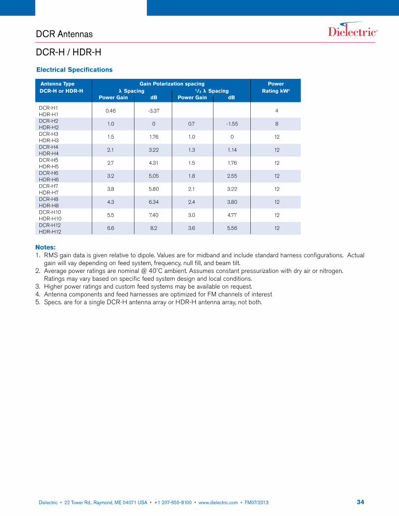
3422 Tower Road, P.O. Box 949, Raymond, ME 04071 • 207-655-8100 • 1-800-341-9678 • Fax: 207-655-8177 • www.dielectric.comDielectric • 22 Tower Rd., Raymond, ME 04071 USA • +1 207-655-8100 • www.dielectric.com • FM07/2013
Notes:1. RMS gain data is given relative to dipole. Values are for midband and include standard harness configurations. Actual
gain will vay depending on feed system, frequency, null fill, and beam tilt.2. Average power ratings are nominal @ 40˚C ambient. Assumes constant pressurization with dry air or nitrogen.
Ratings may vary based on specific feed system design and local conditions.3. Higher power ratings and custom feed systems may be available on request.4. Antenna components and feed harnesses are optimized for FM channels of interest5. Specs. are for a single DCR-H antenna array or HDR-H antenna array, not both.
Electrical Specifications
Antenna Type Gain Polarization spacing Power DCR-H or HDR-H λ Spacing 1/2 λ Spacing Rating kW3
Power Gain dB Power Gain dB
DCR-H1HDR-H1DCR-H2HDR-H2DCR-H3HDR-H3DCR-H4HDR-H4DCR-H5HDR-H5DCR-H6HDR-H6DCR-H7HDR-H7DCR-H8HDR-H8DCR-H10HDR-H10DCR-H12HDR-H12
0.46
1.0
1.5
2.1
2.7
3.2
3.8
4.3
5.5
6.6
-3.37
0
1.76
3.22
4.31
5.05
5.80
6.34
7.40
8.2
0.7
1.0
1.3
1.5
1.8
2.1
2.4
3.0
3.6
4
8
12
12
12
12
12
12
12
12
-1.55
0
1.14
1.76
2.55
3.22
3.80
4.77
5.56
DCR Antennas
DCR-H / HDR-H

3522 Tower Road, P.O. Box 949, Raymond, ME 04071 • 207-655-8100 • 1-800-341-9678 • Fax: 207-655-8177 • www.dielectric.comDielectric • 22 Tower Rd., Raymond, ME 04071 USA • +1 207-655-8100 • www.dielectric.com • FM07/2013
Broadband Systems for Multiplexing Signals
DCR-S / DCR-M
• Superior bandwidth for analog or -10dB IBOC, or both
• Broadband arrays from 1/2 wave spaced to full wave spacing (see chart)
• Arrays from 2 to 12 bays• Circular polarization• Left or right hand polarization• Full FM band operation available in 1/2
spaced arrays
• Low VSWR• Series fed arrays• High input power capability• Simple design leads to ease of installation• Common amplification or high level combined with single input• Beam tilt and null fill available• Radomes or deicers available
Dielectric offers DCR-M and DCR-S models at ½ wavelength spacing that can cover the entire FM band for purposes of multiplexing signals. The broadband DRCM and DCR-S antennas can be fed with a single line input or a dual input for redundancy purposes.The input power can be significantly higher than our DCR-M models and we can feed with dual 6” inputs. Average Power ranges from 40 kW to over 120 kW are available and each system is quickly designed to meet the needs of the broadcaster and market they serve.The antenna design is offered with customer required beam tilt and null fill requirements. Custom selections are engineered and manufactured at our facility. In addition, both the DCR-M and DCR-S are offered with heaters and radomes.The full band operation allows broadcasters to simulcast from one antenna. The antenna is designed to handle the peak power of multiple signals including IBOC signals at -10 dB. The DCR-S was designed to handle more stations at a higher safety margin for multipke signals including IBOC at -10 dB. The higher peak power design should be considered. Dielectric takes pride in the safe power levels at the design stage to ensure the broadcaster has an antenna that will produce sound quality signals for many years.

3622 Tower Road, P.O. Box 949, Raymond, ME 04071 • 207-655-8100 • 1-800-341-9678 • Fax: 207-655-8177 • www.dielectric.comDielectric • 22 Tower Rd., Raymond, ME 04071 USA • +1 207-655-8100 • www.dielectric.com • FM07/2013
1/2 Wave Spaced Funky Elbow Full Wave Spaced
2E 15 MHz 7 MHz 5 MHz
2C 12 MHz 7 MHz 5 MHz
3E 15 MHz 7 MHz 5 MHz
4E 8 MHz 5 MHz 3 MHz
4C 15 MHz 7 MHz 5 MHz
5E 6 MHz 4 MHz 3 MHz
5C 15 MHz 7 MHz 5 MHz
6E 5 MHz 4 MHz 3 MHz
6C 15 MHz 7 MHz 5 MHz
8C 8 MHz 5 MHz 3 MHz
10C 15 MHz 7 MHz 5 MHz
12C 15 MHz 7 MHz 5 MHz
Dielectric FM Achievable Bandwidths
E = End Fed C = Center Fed
Notes:Discuss additional bandwidth considerations with Dielectric sales representative.Additional bandwidths available upon request.
Refer to DCR-S/HDR-S (pages 20-22) and DCR-M/HDR-M (pages 25-27) for specifications.
Broadband Systems for Multiplexing Signals
DCR-S / DCR-M
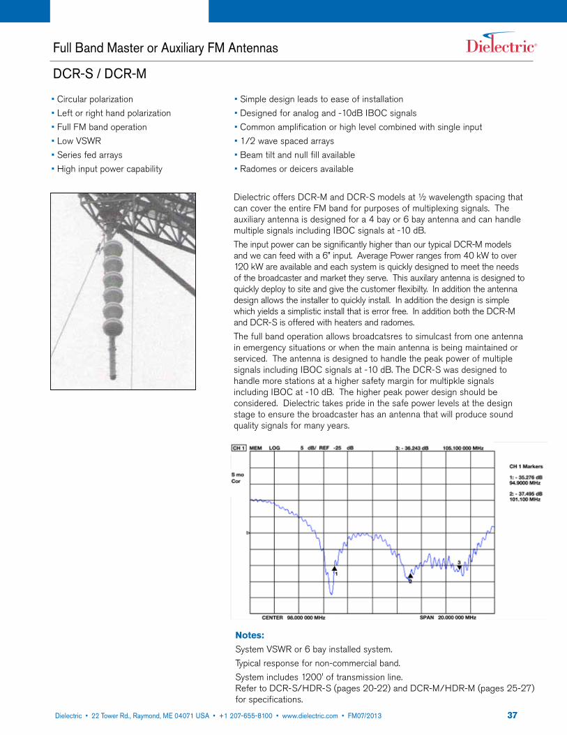
3722 Tower Road, P.O. Box 949, Raymond, ME 04071 • 207-655-8100 • 1-800-341-9678 • Fax: 207-655-8177 • www.dielectric.comDielectric • 22 Tower Rd., Raymond, ME 04071 USA • +1 207-655-8100 • www.dielectric.com • FM07/2013
Full Band Master or Auxiliary FM Antennas
DCR-S / DCR-M
Notes: System VSWR or 6 bay installed system.Typical response for non-commercial band.System includes 1200' of transmission line.Refer to DCR-S/HDR-S (pages 20-22) and DCR-M/HDR-M (pages 25-27) for specifications.
• Circular polarization• Left or right hand polarization• Full FM band operation • Low VSWR• Series fed arrays• High input power capability
• Simple design leads to ease of installation• Designed for analog and -10dB IBOC signals• Common amplification or high level combined with single input• 1/2 wave spaced arrays• Beam tilt and null fill available• Radomes or deicers available
Dielectric offers DCR-M and DCR-S models at ½ wavelength spacing that can cover the entire FM band for purposes of multiplexing signals. The auxiliary antenna is designed for a 4 bay or 6 bay antenna and can handle multiple signals including IBOC signals at -10 dB.The input power can be significantly higher than our typical DCR-M models and we can feed with a 6” input. Average Power ranges from 40 kW to over 120 kW are available and each system is quickly designed to meet the needs of the broadcaster and market they serve. This auxilary antenna is designed to quickly deploy to site and give the customer flexibilty. In addition the antenna design allows the installer to quickly install. In addition the design is simple which yields a simplistic install that is error free. In addition both the DCR-M and DCR-S is offered with heaters and radomes.The full band operation allows broadcatsres to simulcast from one antenna in emergency situations or when the main antenna is being maintained or serviced. The antenna is designed to handle the peak power of multiple signals including IBOC signals at -10 dB. The DCR-S was designed to handle more stations at a higher safety margin for multipkle signals including IBOC at -10 dB. The higher peak power design should be considered. Dielectric takes pride in the safe power levels at the design stage to ensure the broadcaster has an antenna that will produce sound quality signals for many years.
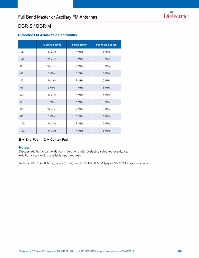
3822 Tower Road, P.O. Box 949, Raymond, ME 04071 • 207-655-8100 • 1-800-341-9678 • Fax: 207-655-8177 • www.dielectric.comDielectric • 22 Tower Rd., Raymond, ME 04071 USA • +1 207-655-8100 • www.dielectric.com • FM07/2013
Full Band Master or Auxiliary FM Antennas
DCR-S / DCR-M
1/2 Wave Spaced Funky Elbow Full Wave Spaced
2E 15 MHz 7 MHz 5 MHz
2C 12 MHz 7 MHz 5 MHz
3E 15 MHz 7 MHz 5 MHz
4E 8 MHz 5 MHz 3 MHz
4C 15 MHz 7 MHz 5 MHz
5E 6 MHz 4 MHz 3 MHz
5C 15 MHz 7 MHz 5 MHz
6E 5 MHz 4 MHz 3 MHz
6C 15 MHz 7 MHz 5 MHz
8C 8 MHz 5 MHz 3 MHz
10C 15 MHz 7 MHz 5 MHz
12C 15 MHz 7 MHz 5 MHz
Dielectric FM Achievable Bandwidths
E = End Fed C = Center Fed
Notes:Discuss additional bandwidth considerations with Dielectric sales representative.Additional bandwidths available upon request.
Refer to DCR-S/HDR-S (pages 20-22) and DCR-M/HDR-M (pages 25-27) for specifications.
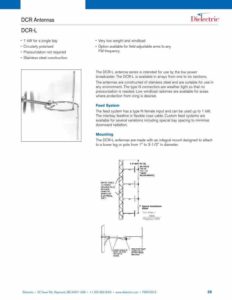
3922 Tower Road, P.O. Box 949, Raymond, ME 04071 • 207-655-8100 • 1-800-341-9678 • Fax: 207-655-8177 • www.dielectric.comDielectric • 22 Tower Rd., Raymond, ME 04071 USA • +1 207-655-8100 • www.dielectric.com • FM07/2013
DCR Antennas
DCR-L
* λ in inches =
11803Frequency in MHz
Typical Installation Detail
The DCR-L antenna series is intended for use by the low power broadcaster. The DCR-L is available in arrays from one to six sections.The antennas are constructed of stainless steel and are suitable for use in any environment. The type N connectors are weather tight so that no pressurization is needed. Low windload radomes are available for areas where protection from icing is desired.
Feed SystemThe feed system has a type N female input and can be used up to 1 kW. The interbay feedline is flexible coax cable. Custom feed systems are available for several variations including special bay spacing to minimize downward radiation.
MountingThe DCR-L antennas are made with an integral mount designed to attach to a tower leg or pole from 1" to 3-1/2" in diameter.
• 1 kW for a single bay• Circularly polarized• Pressurization not required• Stainless steel construction
• Very low weight and windload• Option available for field adjustable arms to any
FM frequency
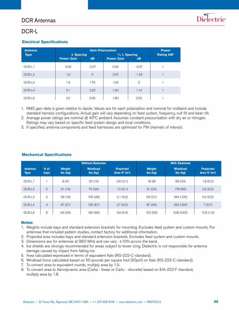
4022 Tower Road, P.O. Box 949, Raymond, ME 04071 • 207-655-8100 • 1-800-341-9678 • Fax: 207-655-8177 • www.dielectric.comDielectric • 22 Tower Rd., Raymond, ME 04071 USA • +1 207-655-8100 • www.dielectric.com • FM07/2013
Electrical Specifications
Antenna Gain Polarization1 Power Type λ Spacing 1/2 λ Spacing Rating kW3
Power Gain dB Power Gain dB
DCR-L1 0.46 -3.37 0.46 -3.37 1
DCR-L2 1.0 0 0.70 -1.55 1
DCR-L3 1.5 1.76 1.00 0 1
DCR-L4 2.1 3.22 1.30 1.14 1
DCR-L6 3.2 5.05 1.80 2.55 1
1. RMS gain data is given relative to dipole. Values are for each polarization and nominal for midband and include standard harness configurations. Actual gain will vary depending on feed system, frequency, null fill and bean tilt.
2. Average power ratings are nominal @ 40°C ambient. Assumes constant pressurization with dry air or nitrogen. Ratings may vary based on specific feed system design and local conditions.
3. If specified, antenna components and feed harnesses are optimized for FM channels of interest.
DCR Antennas
DCR-L
Notes:1. Weights include bays and standard extension brackets for mounting. Excludes feed system and custom mounts. For
antennas that included pattern studies, contact factory for additional information.2. Projected area includes bays and standard extension brackets. Excludes feed system and custom mounts.3. Dimensions are for antennas at 98.0 MHz and can vary ±10% across the band.4. Ice shields are strongly recommended for areas subject to tower icing. Dielectric is not responsible for antenna
damage caused by impact from falling ice.5. Area calculated expressed in terms of equivalent flats (RS-222-C-standard).6. Windload force calculated based on 50 pounds per square foot (50psf) on flats (RS-222-C-standard).7. To convert area to equivalent rounds, multiply area by 1.5.8. To convert area to Aerodynamic area (CaAa - linear or CaAc - discrete) based on EIA-222-F standard,
multiply area by 1.8.
Mechanical Specifications
Without Radomes With Radomes
Antenna # of Weight Windload Projected Weight Windload Projected Type bays lbs (kg) lbs (kg) Area ft2 (m2) lbs (kg) lbs (kg) Area ft2 (m2)
DCR-L1 1 8 (4) 30 (14) 0.6 (0.1) 18 (8) 88 (40) 1.8 (0.2)
DCR-L2 2 31 (14) 75 (34) 1.5 (0.1) 51 (23) 176 (80) 3.5 (0.3)
DCR-L3 3 39 (18) 105 (48) 2.1 (0.2) 69 (31) 264 (120) 5.3 (0.5)
DCR-L4 4 47 (21) 135 (61) 2.7 (0.3) 87 (40) 352 (160) 7 (0.7)
DCR-L6 6 63 (29) 195 (89) 3.9 (0.4) 123 (56) 528 (240) 10.6 (1.0)
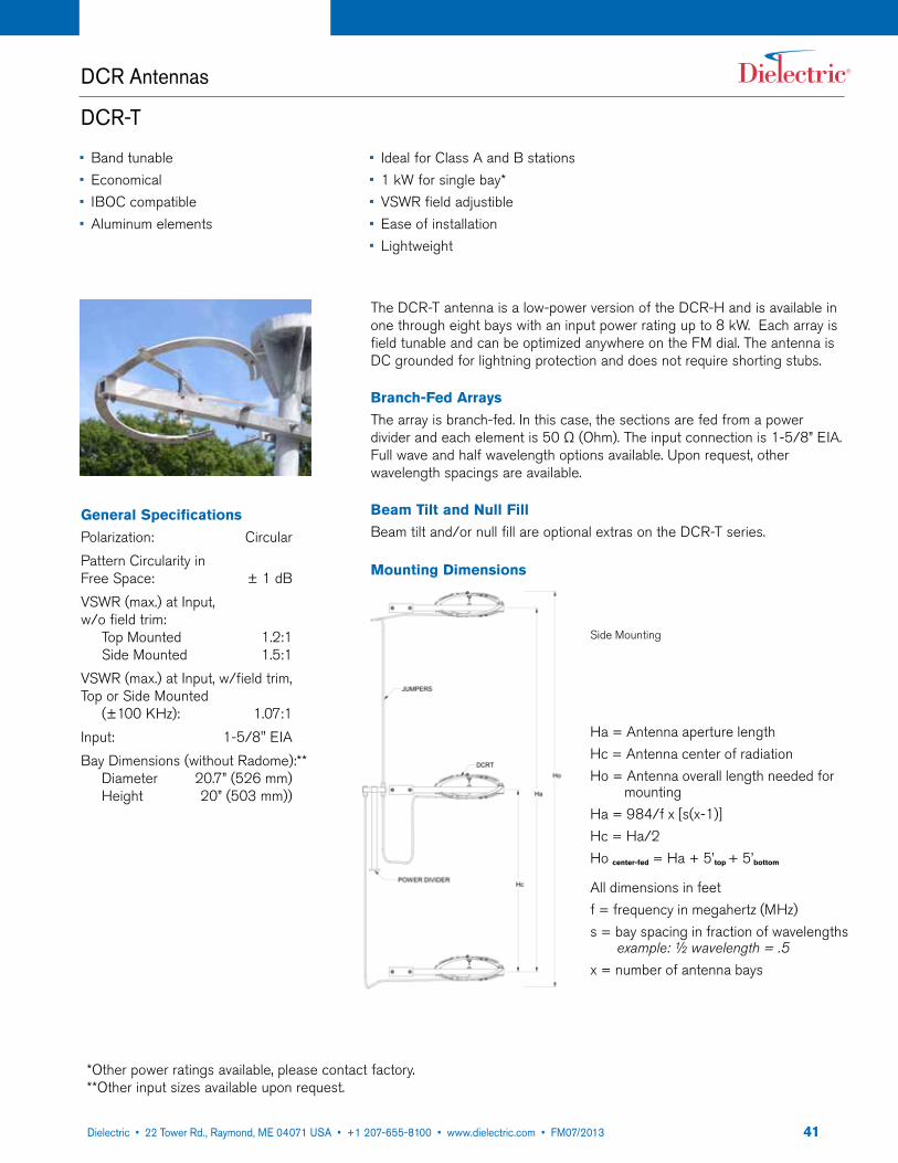
4122 Tower Road, P.O. Box 949, Raymond, ME 04071 • 207-655-8100 • 1-800-341-9678 • Fax: 207-655-8177 • www.dielectric.comDielectric • 22 Tower Rd., Raymond, ME 04071 USA • +1 207-655-8100 • www.dielectric.com • FM07/2013
*Other power ratings available, please contact factory.**Other input sizes available upon request.
DCR Antennas
DCR-T
The DCR-T antenna is a low-power version of the DCR-H and is available in one through eight bays with an input power rating up to 8 kW. Each array is field tunable and can be optimized anywhere on the FM dial. The antenna is DC grounded for lightning protection and does not require shorting stubs.
Branch-Fed ArraysThe array is branch-fed. In this case, the sections are fed from a power divider and each element is 50 Ω (Ohm). The input connection is 1-5/8” EIA. Full wave and half wavelength options available. Upon request, other wavelength spacings are available.
Beam Tilt and Null FillBeam tilt and/or null fill are optional extras on the DCR-T series.
• Band tunable• Economical• IBOC compatible• Aluminum elements
• Ideal for Class A and B stations• 1 kW for single bay*• VSWR field adjustible• Ease of installation• Lightweight
General SpecificationsPolarization: CircularPattern Circularity in Free Space: ± 1 dBVSWR (max.) at Input, w/o field trim: Top Mounted 1.2:1 Side Mounted 1.5:1 VSWR (max.) at Input, w/field trim, Top or Side Mounted (±100 KHz): 1.07:1Input: 1-5/8" EIABay Dimensions (without Radome):** Diameter 20.7” (526 mm) Height 20” (503 mm))
Ha = Antenna aperture lengthHc = Antenna center of radiationHo = Antenna overall length needed for mountingHa = 984/f x [s(x-1)]Hc = Ha/2Ho center-fed = Ha + 5’top + 5’bottom
All dimensions in feetf = frequency in megahertz (MHz)s = bay spacing in fraction of wavelengths example: ½ wavelength = .5x = number of antenna bays
Mounting Dimensions
Side Mounting

4222 Tower Road, P.O. Box 949, Raymond, ME 04071 • 207-655-8100 • 1-800-341-9678 • Fax: 207-655-8177 • www.dielectric.comDielectric • 22 Tower Rd., Raymond, ME 04071 USA • +1 207-655-8100 • www.dielectric.com • FM07/2013
Notes:1. RMS gain data is given relative to dipole. Values are for
midband and include standard harness configurations. Actual gain will vay depending on feed system, frequency, null fill, and beam tilt.
2. Average power ratings are nominal @ 40˚C ambient. Ratings may vary based on specific feed system design and local conditions.
3. Higher power ratings and custom feed systems may be available on request.
4. Antenna components and feed harnesses are optimized for FM channels of interest.
Electrical Specifications
Antenna Gain Polarization spacing Power Type λ Spacing Rating kW3
Power Gain dB
DCRT1
DCRT2
DCRT3
DCRT4
DCRT5
DCRT6
DCRT7
DCRT8
0.46
1.0
1.5
2.1
2.7
3.2
3.8
4.3
-3.37
0
1.76
3.22
4.31
5.05
5.80
6.34
1
2
3
4
5
6
7
8
Notes:1. CaAc and weight include bays, power
dividers, inter-bay feedlines, and standard extension brackets for mounting.
2. Dimensions are for antennas at 98.0 MHz and can vary across the band.
3. Wind area (CaAc) is calculated per the TIA/EIA-222-F standard.
Mechanical Specifications
Antenna # of Weight lbs (kg) CaAc ft2 (m3) Type Bays λ Spaced 1/2 λ Spaced λ Spaced 1/2 λ Spaced
DCRT1
DCRT2
DCRT3
DCRT4
DCRT5
DCRT6
DCRT7
DCRT8
17.5 (8.0)
47.4 (21.5)
67.9 (30.9)
90.2 (41.0)
114.0 (51.8)
145.8 (66.3)
168.3 (76.5)
190.4 (86.5)
17.5 (8.0)
46.5 (21.1)
66.1 (30.0)
86.0 (39.1)
106.5 (48.4)
142.2 (64.6)
162.0 (73.6)
182.0 (82.7)
2.4 (0.22)
6.0 (0.56)
9.4 (0.87)
13.3 (1.24)
17.8 (1.65)
20.3 (1.89)
24.6 (2.29)
28.7 (2.67)
2.4 (0.22)
5.7 (0.53)
8.8 (0.82)
12.0 (1.11)
15.4 (1.43)
18.8 (1.74)
22.0 (2.04)
25.3 (2.35)
1
2
3
4
5
6
7
8
DCR Antennas
DCR-T
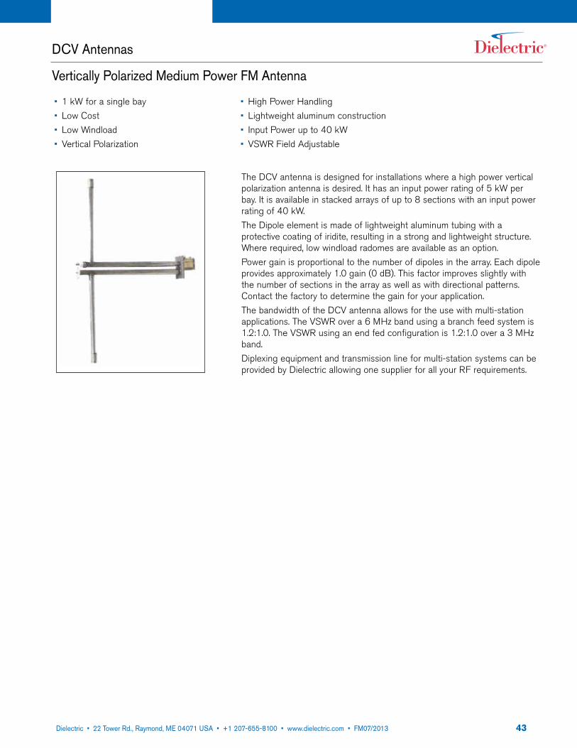
4322 Tower Road, P.O. Box 949, Raymond, ME 04071 • 207-655-8100 • 1-800-341-9678 • Fax: 207-655-8177 • www.dielectric.comDielectric • 22 Tower Rd., Raymond, ME 04071 USA • +1 207-655-8100 • www.dielectric.com • FM07/2013
DCV Antennas
Vertically Polarized Medium Power FM Antenna
The DCV antenna is designed for installations where a high power vertical polarization antenna is desired. It has an input power rating of 5 kW per bay. It is available in stacked arrays of up to 8 sections with an input power rating of 40 kW.The Dipole element is made of lightweight aluminum tubing with a protective coating of iridite, resulting in a strong and lightweight structure. Where required, low windload radomes are available as an option.Power gain is proportional to the number of dipoles in the array. Each dipole provides approximately 1.0 gain (0 dB). This factor improves slightly with the number of sections in the array as well as with directional patterns. Contact the factory to determine the gain for your application.The bandwidth of the DCV antenna allows for the use with multi-station applications. The VSWR over a 6 MHz band using a branch feed system is 1.2:1.0. The VSWR using an end fed configuration is 1.2:1.0 over a 3 MHz band.Diplexing equipment and transmission line for multi-station systems can be provided by Dielectric allowing one supplier for all your RF requirements.
• 1 kW for a single bay• Low Cost• Low Windload• Vertical Polarization
• High Power Handling• Lightweight aluminum construction• Input Power up to 40 kW• VSWR Field Adjustable
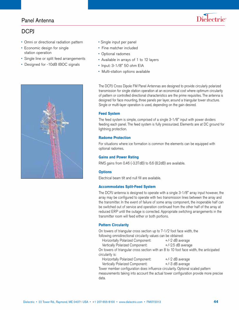
4422 Tower Road, P.O. Box 949, Raymond, ME 04071 • 207-655-8100 • 1-800-341-9678 • Fax: 207-655-8177 • www.dielectric.comDielectric • 22 Tower Rd., Raymond, ME 04071 USA • +1 207-655-8100 • www.dielectric.com • FM07/2013
Panel Antenna
DCPJ
The DCPJ Cross Dipole FM Panel Antennas are designed to provide circularly polarized transmission for single station operation at an economical cost where optimum circularity of pattern or controlled directional characteristics are the prime requisites. The antenna is designed for face mounting, three panels per layer, around a triangular tower structure. Single or multi-layer operation is used, depending on the gain desired.
Feed SystemThe feed system is simple, comprised of a single 3-1/8" input with power dividers feeding each panel. The feed system is fully pressurized. Elements are at DC ground for lightning protection.
Radome ProtectionFor situations where ice formation is common the elements can be equipped with optional radomes.
Gains and Power RatingRMS gains from 0.46 (-3.37dB) to 6.6 (8.2dB) are available.
OptionsElectrical beam tilt and null fill are available.
Accommodates Split-Feed SystemThe DCPJ antenna is designed to operate with a single 3-1/8" array input however, the array may be configured to operate with two transmission lines between the array and the transmitter. In the event of failure of some array component, the inoperable half can be switched out of service and operation continued from the other half of the array at reduced ERP until the outage is corrected. Appropriate switching arrangements in the transmitter room will feed either or both portions.
Pattern CircularityOn towers of triangular cross section up to 7-1/2 foot face width, the following omnidirectional circularity values can be obtained: Horizontally Polarized Component: +/-2 dB average Vertically Polarized Component: +/-2.5 dB averageOn towers of triangular cross section with an 8 to 10 foot face width, the anticipated circularity is: Horizontally Polarized Component: +/-2 dB average Vertically Polarized Component: +/-3 dB averageTower member configuration does influence circularity. Optional scaled pattern measurements taking into account the actual tower configuration provide more precise data.
• Omni or directional radiation pattern• Economic design for single
station operation• Single line or split feed arrangements• Designed for -10dB IBOC signals
• Single input per panel• Fine matcher included• Optional radomes• Available in arrays of 1 to 12 layers• Input: 3-1/8" 50 ohm EIA• Multi-station options available

4522 Tower Road, P.O. Box 949, Raymond, ME 04071 • 207-655-8100 • 1-800-341-9678 • Fax: 207-655-8177 • www.dielectric.comDielectric • 22 Tower Rd., Raymond, ME 04071 USA • +1 207-655-8100 • www.dielectric.com • FM07/2013
Panel Antenna
DCPJ
Electrical Specifications
Antenna Type # of Gain Polarization1 Power layers λ Spacing Rating kW3
Power Gain dB
DCPJ-1 1 0.46 -3.37 10
DCPJ-2 2 1.0 0 20
DCPJ-3 3 1.5 1.76 30
DCPJ-4 4 2.1 3.22 40
DCPJ-5 5 2.7 4.31 45
DCPJ-6 6 3.3 5.19 45
DCPJ-8 8 4.4 6.43 45
DCPJ-10 10 5.5 7.40 45
DCPJ-12 12 6.6 8.20 45
Notes:1. RMS gain data is given relative to dipole. Values are for each polarization and nominal for
midband and include standard harness configurations. Actual gain will vary depending on feed system, frequency, null fill and bean tilt.
2. Average power ratings are nominal @ 40°C (104˚F) ambient. Assumes constant pressurization with dry air or nitro-gen. Ratings may vary based on specific feed system design and local conditions.
3. Higher power ratings and custom feed systems may be available on request.4. Antenna components and feed harnesses are optimized for FM channels of interest.
Input VSWRAt the input to the antenna feed system the VSWR is 1.1:1 or better across the station channel bandwidth with field adjustment of the variable transformer provided.
WindloadsThe antenna is designed to withstand winds of 110 mph. Under those conditions the windload on a layer of panels is shown in the table below. The values were calculated as follows:Windload =Frontal Windload +(2)(Frontal Windload)(cos 60 degrees). Therefore the tabulated values do not include the effect of the tower or assume any shielding of one panel by another panel. Weights for the various numbers of layers are also given.
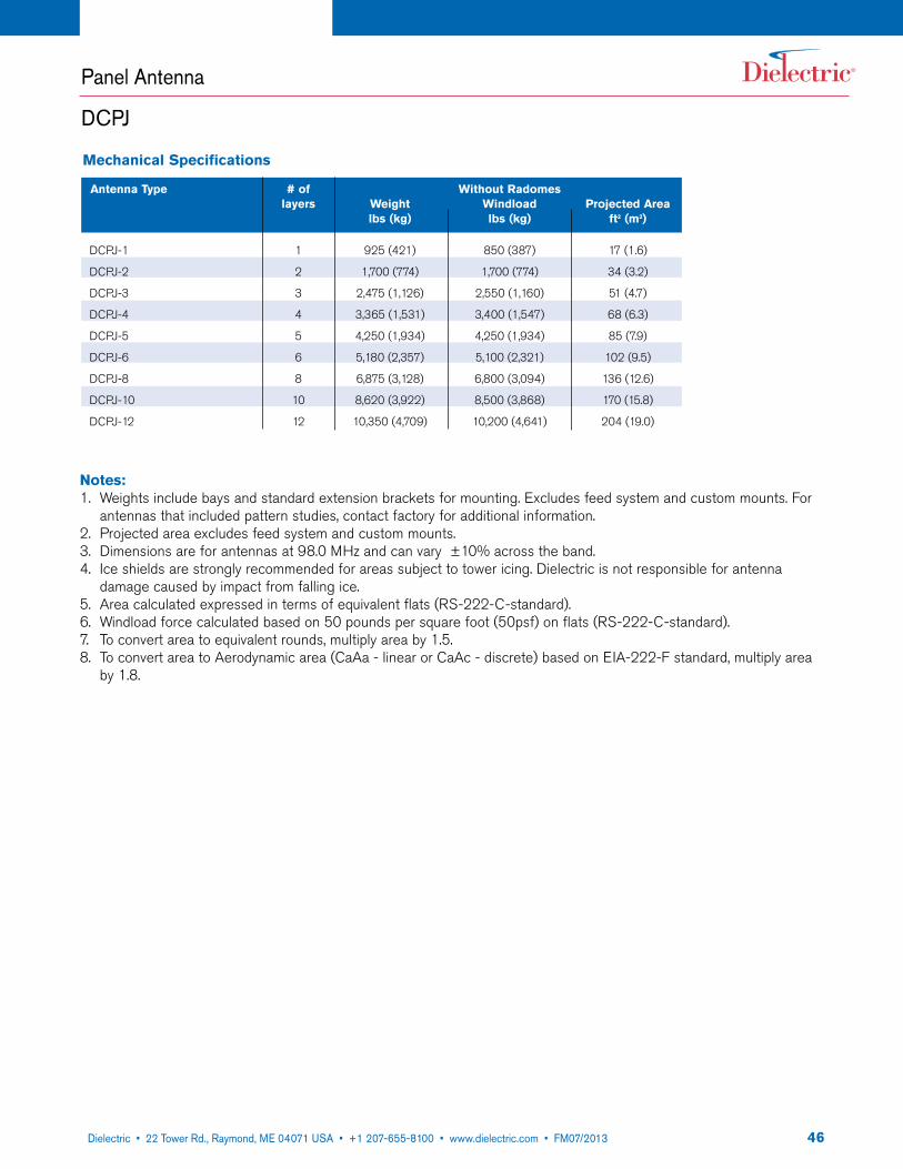
4622 Tower Road, P.O. Box 949, Raymond, ME 04071 • 207-655-8100 • 1-800-341-9678 • Fax: 207-655-8177 • www.dielectric.comDielectric • 22 Tower Rd., Raymond, ME 04071 USA • +1 207-655-8100 • www.dielectric.com • FM07/2013
Mechanical Specifications
Antenna Type # of Without Radomes layers Weight Windload Projected Area lbs (kg) lbs (kg) ft2 (m2)
DCPJ-1 1 925 (421) 850 (387) 17 (1.6)
DCPJ-2 2 1,700 (774) 1,700 (774) 34 (3.2)
DCPJ-3 3 2,475 (1,126) 2,550 (1,160) 51 (4.7)
DCPJ-4 4 3,365 (1,531) 3,400 (1,547) 68 (6.3)
DCPJ-5 5 4,250 (1,934) 4,250 (1,934) 85 (7.9)
DCPJ-6 6 5,180 (2,357) 5,100 (2,321) 102 (9.5)
DCPJ-8 8 6,875 (3,128) 6,800 (3,094) 136 (12.6)
DCPJ-10 10 8,620 (3,922) 8,500 (3,868) 170 (15.8)
DCPJ-12 12 10,350 (4,709) 10,200 (4,641) 204 (19.0)
Notes:1. Weights include bays and standard extension brackets for mounting. Excludes feed system and custom mounts. For
antennas that included pattern studies, contact factory for additional information.2. Projected area excludes feed system and custom mounts.3. Dimensions are for antennas at 98.0 MHz and can vary ±10% across the band.4. Ice shields are strongly recommended for areas subject to tower icing. Dielectric is not responsible for antenna
damage caused by impact from falling ice.5. Area calculated expressed in terms of equivalent flats (RS-222-C-standard).6. Windload force calculated based on 50 pounds per square foot (50psf) on flats (RS-222-C-standard).7. To convert area to equivalent rounds, multiply area by 1.5.8. To convert area to Aerodynamic area (CaAa - linear or CaAc - discrete) based on EIA-222-F standard, multiply area
by 1.8.
Panel Antenna
DCPJ

4722 Tower Road, P.O. Box 949, Raymond, ME 04071 • 207-655-8100 • 1-800-341-9678 • Fax: 207-655-8177 • www.dielectric.comDielectric • 22 Tower Rd., Raymond, ME 04071 USA • +1 207-655-8100 • www.dielectric.com • FM07/2013
Dielectric offers state-of-the-art anechoic chamber FM pattern measurements, or full-scale pattern measurements. A PATTERN STUDY measures the effect a tower has on the antenna signal. PATTERN OPTIMIZATION is a modification of the pattern to meet specific customer requirements.In a Pattern Study, the antenna is mounted on a replica of your tower and measurements are made to determine the relative signal strength around the tower. This replica includes all transmission line, waveguide runs, conduit and ladder assemblies passing through the antenna aperture. The measurements are repeated for different mountings and orientations of the antenna and the data is used to select an antenna mounting which best meets your requirements. Optimization may require the addition of parasitic radiating elements to be mounted near the antenna to the direct pattern in a more desired direction. Dielectric's FM azimuth pattern measurements are performed in the specially designed anechoic chamber operating at 4.4 times FM carrier frequencies. At this frequency, the antenna, tower structure, and transmission lines can be accurately modeled to 4.4:1 scale. The anechoic chamber allows for a more detailed study, in a noise and reflection free environment, resulting in the most accurate results.
Test MethodThe antenna/structure rotates 360 degrees while receiving a signal from a source antenna. The source is fed by a signal generator with directional coupler located at the antenna input. A reference signal is obtained from this coupler and compared to the “receive” signal of the antenna under test. The transmit and scale model antennas are mounted at identical elevations and at the opposite ends of the chamber. A network analyzer supplies the RF signal to the source antenna at 4.4 times the fundamental FM frequency. The network analyzer also receives the signal that is intercepted by the antenna under test. The received signal of each polarization is converted to a relative level, referenced to the source. This level is stored on a computer acting as the master controller. The computer controls the measurement system via IEEE-488 control bus through a GPIB card.
Pattern Study

4822 Tower Road, P.O. Box 949, Raymond, ME 04071 • 207-655-8100 • 1-800-341-9678 • Fax: 207-655-8177 • www.dielectric.comDielectric • 22 Tower Rd., Raymond, ME 04071 USA • +1 207-655-8100 • www.dielectric.com • FM07/2013
Pre-OptimizationPattern exemplifies vertical component distortion caused by mounting structure.
Post OptimizationUsing two parasitic elements vertical circularity has improved to near free space performance.
330
300
240
210
180
150
120
90
60
30
0
270
5 dB
10 dB
15 dB
20 dB
20
15
10
5
5 10 15 20 20 15 10 5
330
300
240
210
180
150
120
90
60
30
0
2705 10 15 20 20 15 10 5
5 dB
10 dB
15 dB
20 dB
20
15
10
5
Pattern Optimization
HorizontalVertical
HorizontalVertical

4922 Tower Road, P.O. Box 949, Raymond, ME 04071 • 207-655-8100 • 1-800-341-9678 • Fax: 207-655-8177 • www.dielectric.comDielectric • 22 Tower Rd., Raymond, ME 04071 USA • +1 207-655-8100 • www.dielectric.com • FM07/2013
FM Elevation Patterns
1
0.9
0.8
0.7
0.6
0.5
0.4
0.3
0.2
0.1
00 10 20 30 40 50 60 70 80
Degrees below Horizontal
-3 dB
-5 dB
-10 dB
-20 dB
1
0.9
0.8
0.7
0.6
0.5
0.4
0.3
0.2
0.1
00 10 20 30 40 50 60 70 80
Degrees below Horizontal
-3 dB
-5 dB
-10 dB
-20 dB
1
0.9
0.8
0.7
0.6
0.5
0.4
0.3
0.2
0.1
00 10 20 30 40 50 60 70 80
Degrees below Horizontal
-3 dB
-5 dB
-10 dB
-20 dB
2 Bay λ 4 Bay λ 6 Bay λ
1
0.9
0.8
0.7
0.6
0.5
0.4
0.3
0.2
0.1
00 10 20 30 40 50 60 70 80
Degrees below Horizontal
-3 dB
-5 dB
-10 dB
-20 dB
1
0.9
0.8
0.7
0.6
0.5
0.4
0.3
0.2
0.1
00 10 20 30 40 50 60 70 80
Degrees below Horizontal
-3 dB
-5 dB
-10 dB
-20 dB
1
0.9
0.8
0.7
0.6
0.5
0.4
0.3
0.2
0.1
00 10 20 30 40 50 60 70 80
Degrees below Horizontal
-3 dB
-5 dB
-10 dB
-20 dB
8 Bay λ 2 Bay λ/2 4 Bay λ/2
1
0.9
0.8
0.7
0.6
0.5
0.4
0.3
0.2
0.1
00 10 20 30 40 50 60 70 80
Degrees below Horizontal
-3 dB
-5 dB
-10 dB
-20 dB
1
0.9
0.8
0.7
0.6
0.5
0.4
0.3
0.2
0.1
00 10 20 30 40 50 60 70 80
Degrees below Horizontal
-3 dB
-5 dB
-10 dB
-20 dB
6 Bay λ/2 8 Bay λ/2
Subject to change.
Check www.dielectric.com for latest patterns and our DASP (Dielectric System Planning software.)
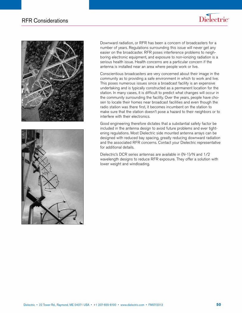
5022 Tower Road, P.O. Box 949, Raymond, ME 04071 • 207-655-8100 • 1-800-341-9678 • Fax: 207-655-8177 • www.dielectric.comDielectric • 22 Tower Rd., Raymond, ME 04071 USA • +1 207-655-8100 • www.dielectric.com • FM07/2013
RFR Considerations
Downward radiation, or RFR has been a concern of broadcasters for a number of years. Regulations surrounding this issue will never get any easier on the broadcaster. RFR poses interference problems to neigh-boring electronic equipment, and exposure to non-ionizing radiation is a serious health issue. Health concerns are a particular concern if the antenna is installed near an area where people work or live.
Conscientious broadcasters are very concerned about their image in the community as to providing a safe environment in which to work and live. This poses numerous issues since a broadcast facility is an expensive undertaking and is typically constructed as a permanent location for the station. In many cases, it is difficult to predict what changes will occur in the community surrounding the facility. Over the years, people have cho-sen to locate their homes near broadcast facilities and even though the radio station was there first, it becomes incumbent on the station to make sure that the station doesn’t pose a hazard to their neighbors or to interfere with their electronics.
Good engineering therefore dictates that a substantial safety factor be included in the antenna design to avoid future problems and ever tight-ening regulations. Most Dielectric side mounted antenna arrays can be designed with reduced bay spacing, greatly reducing downward radiation and the associated RFR concerns. Contact your Dielectric representative for additional details.
Dielectric’s DCR series antennas are available in (N-1)/N and 1/2 wavelength designs to reduce RFR exposure. They offer a solution with lower weight and windloading.
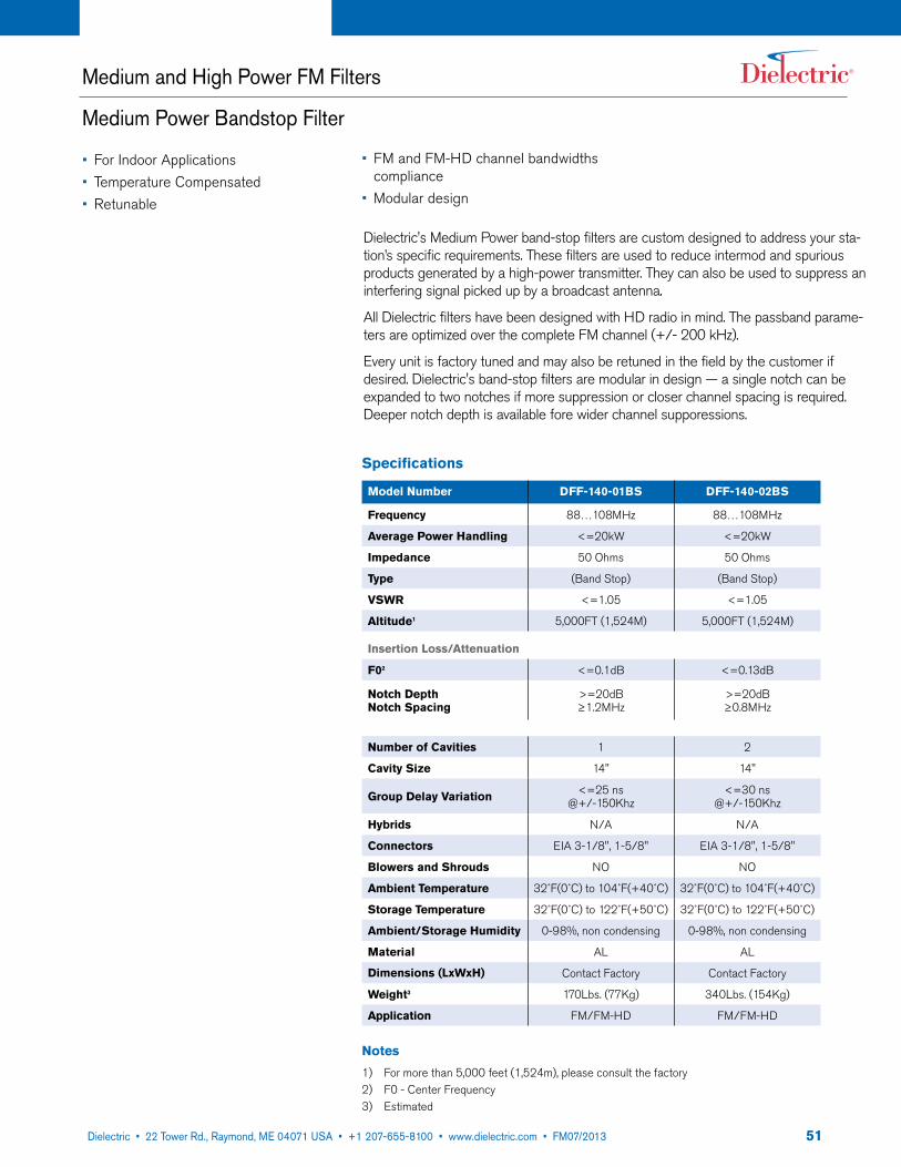
5122 Tower Road, P.O. Box 949, Raymond, ME 04071 • 207-655-8100 • 1-800-341-9678 • Fax: 207-655-8177 • www.dielectric.comDielectric • 22 Tower Rd., Raymond, ME 04071 USA • +1 207-655-8100 • www.dielectric.com • FM07/2013
Medium and High Power FM Filters
Medium Power Bandstop Filter
Dielectric's Medium Power band-stop filters are custom designed to address your sta-tion’s specific requirements. These filters are used to reduce intermod and spurious products generated by a high-power transmitter. They can also be used to suppress an interfering signal picked up by a broadcast antenna.
All Dielectric filters have been designed with HD radio in mind. The passband parame-ters are optimized over the complete FM channel (+/- 200 kHz).
Every unit is factory tuned and may also be retuned in the field by the customer if desired. Dielectric's band-stop filters are modular in design — a single notch can be expanded to two notches if more suppression or closer channel spacing is required. Deeper notch depth is available fore wider channel supporessions.
Specifications
Model Number DFF-140-01BS DFF-140-02BS
Frequency 88…108MHz 88…108MHz
Average Power Handling <=20kW <=20kW
Impedance 50 Ohms 50 Ohms
Type (Band Stop) (Band Stop)
VSWR <=1.05 <=1.05
Altitude1 5,000FT (1,524M) 5,000FT (1,524M)
Insertion Loss/Attenuation
F02 <=0.1dB <=0.13dB
Notch Depth Notch Spacing
>=20dB ≥1.2MHz
>=20dB ≥0.8MHz
Number of Cavities 1 2
Cavity Size 14" 14"
Group Delay Variation <=25 ns @+/-150Khz
<=30 ns @+/-150Khz
Hybrids N/A N/A
Connectors EIA 3-1/8", 1-5/8" EIA 3-1/8", 1-5/8"
Blowers and Shrouds NO NO
Ambient Temperature 32˚F(0˚C) to 104˚F(+40˚C) 32˚F(0˚C) to 104˚F(+40˚C)
Storage Temperature 32˚F(0˚C) to 122˚F(+50˚C) 32˚F(0˚C) to 122˚F(+50˚C)
Ambient/Storage Humidity 0-98%, non condensing 0-98%, non condensing
Material AL AL
Dimensions (LxWxH) Contact Factory Contact Factory
Weight3 170Lbs. (77Kg) 340Lbs. (154Kg)
Application FM/FM-HD FM/FM-HD
Notes
1) For more than 5,000 feet (1,524m), please consult the factory 2) F0 - Center Frequency3) Estimated
• For Indoor Applications• Temperature Compensated• Retunable
• FM and FM-HD channel bandwidths compliance
• Modular design

5222 Tower Road, P.O. Box 949, Raymond, ME 04071 • 207-655-8100 • 1-800-341-9678 • Fax: 207-655-8177 • www.dielectric.comDielectric • 22 Tower Rd., Raymond, ME 04071 USA • +1 207-655-8100 • www.dielectric.com • FM07/2013
Specifications
Model Number DFF-140-02BP DFF-140-03BP DFF-140-04BP DFF-140-05BP
Frequency 88…108MHz 88…108MHz 88…108MHz 88…108MHz
Average Power Handling4 <=25KW <=20KW <=15KW <=12KW
Average Power with Blowers P<=30kW4 P<=25kW4 P<=20kW4 P<=17kW4
Impedance 50 Ohms 50 Ohms 50 Ohms 50 Ohms
Type (Band Pass) (Band Pass) (Band Pass) (Band Pass)
VSWR <=1.05 <=1.05 <=1.05 <=1.05
Altitude1 5,000FT (1,524M) 5,000FT (1,524M) 5,000FT (1,524M) 5,000FT (1,524M)
Insertion Loss/Attenuation
F02 <=0.15dB <=0.25dB <=0.35dB <=0.45dB
F0+/-1.2 MHz >=4.50dB >=24.0dB >=43.0dB >=62.0dB
Number of Cavities 2 3 4 5
Cavity Size 14" 14" 14" 14"
Group Delay Variation <=30 ns @+/-150Khz
<=50 ns @+/-150Khz
<=70 ns @+/-150Khz
<=160 ns @+/-150Khz
Hybrids N/A N/A N/A N/A
Connectors EIA 3-1/8", 1-5/8" EIA 3-1/8", 1-5/8" EIA 3-1/8", 1-5/8" EIA 3-1/8", 1-5/8"
Ambient Temperature 32˚F(0˚C) to 104˚F(+40˚C) 32˚F(0˚C) to 104˚F(+40˚C) 32˚F(0˚C) to 104˚F(+40˚C) 32˚F(0˚C) to 104˚F(+40˚C)
Storage Temperature 32˚F(0˚C) to 122˚F(+50˚C) 32˚F(0˚C) to 122˚F(+50˚C) 32˚F(0˚C) to 122˚F(+50˚C) 32˚F(0˚C) to 122˚F(+50˚C)
Ambient/Storage Humidity 0-98%, non condensing 0-98%, non condensing 0-98%, non condensing 0-98%, non condensing
Material AL AL AL AL
Dimensions (LxWxH) 28"x17"x57" (711x432x1448mm)
42"x17"x57" (1067x432x1448mm)
56"x17"x57" (1423x432x1448mm)
70"x17"x57" (1778x432x1448mm)
Weight3 320Lbs (145Kg) 480Lbs (218Kg) 630Lbs (286Kg) 790Lbs (359Kg)
Application FM/FM-HD FM/FM-HD FM/FM-HD FM/FM-HD
Notes
1) For more than 5,000 feet (1,524m), please consult the factory 2) F0 - Center Frequency3) Estimated4) Free convection cooled
Medium and High Power FM Filters
Medium Power Bandpass Filter
Dielectric's High Power band-pass and band-stop filters are custom designed to address your station’s specific requirements. These units reduce intermod and spurious product outputs to greater than 80 dB below carrier as specified by the FCC.
All Dielectric filters have been designed with HD radio in mind. The passband parameters are optimized over the complete FM channel (+/- 200 kHz).
Every unit is factory tuned and may also be retuned in the field if desired. Dielectric's band-pass filters are modular in design, a three pole filter can be changed to a four or five pole by simply adding cavities.
• For Indoor Applications• Temperature Compensated• Retunable
• FM and FM-HD channel bandwidths compliance
• Modular design
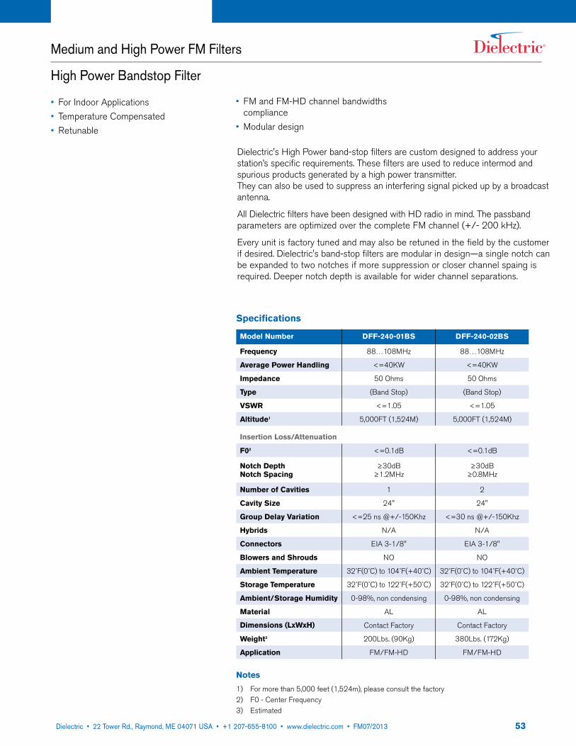
5322 Tower Road, P.O. Box 949, Raymond, ME 04071 • 207-655-8100 • 1-800-341-9678 • Fax: 207-655-8177 • www.dielectric.comDielectric • 22 Tower Rd., Raymond, ME 04071 USA • +1 207-655-8100 • www.dielectric.com • FM07/2013
Medium and High Power FM Filters
High Power Bandstop Filter
Dielectric's High Power band-stop filters are custom designed to address your station’s specific requirements. These filters are used to reduce intermod and spurious products generated by a high power transmitter. They can also be used to suppress an interfering signal picked up by a broadcast antenna.
All Dielectric filters have been designed with HD radio in mind. The passband parameters are optimized over the complete FM channel (+/- 200 kHz).
Every unit is factory tuned and may also be retuned in the field by the customer if desired. Dielectric's band-stop filters are modular in design—a single notch can be expanded to two notches if more suppression or closer channel spaing is required. Deeper notch depth is available for wider channel separations.
Specifications
Model Number DFF-240-01BS DFF-240-02BS
Frequency 88…108MHz 88…108MHz
Average Power Handling <=40KW <=40KW
Impedance 50 Ohms 50 Ohms
Type (Band Stop) (Band Stop)
VSWR <=1.05 <=1.05
Altitude1 5,000FT (1,524M) 5,000FT (1,524M)
Insertion Loss/Attenuation
F02 <=0.1dB <=0.1dB
Notch Depth Notch Spacing
≥30dB ≥1.2MHz
≥30dB ≥0.8MHz
Number of Cavities 1 2
Cavity Size 24" 24"
Group Delay Variation <=25 ns @+/-150Khz <=30 ns @+/-150Khz
Hybrids N/A N/A
Connectors EIA 3-1/8" EIA 3-1/8"
Blowers and Shrouds NO NO
Ambient Temperature 32˚F(0˚C) to 104˚F(+40˚C) 32˚F(0˚C) to 104˚F(+40˚C)
Storage Temperature 32˚F(0˚C) to 122˚F(+50˚C) 32˚F(0˚C) to 122˚F(+50˚C)
Ambient/Storage Humidity 0-98%, non condensing 0-98%, non condensing
Material AL AL
Dimensions (LxWxH) Contact Factory Contact Factory
Weight3 200Lbs. (90Kg) 380Lbs. (172Kg)
Application FM/FM-HD FM/FM-HD
Notes
1) For more than 5,000 feet (1,524m), please consult the factory 2) F0 - Center Frequency3) Estimated
• For Indoor Applications• Temperature Compensated• Retunable
• FM and FM-HD channel bandwidths compliance
• Modular design

5422 Tower Road, P.O. Box 949, Raymond, ME 04071 • 207-655-8100 • 1-800-341-9678 • Fax: 207-655-8177 • www.dielectric.comDielectric • 22 Tower Rd., Raymond, ME 04071 USA • +1 207-655-8100 • www.dielectric.com • FM07/2013
Specifications
Model Number DFF-240-02BP DFF-240-03BP DFF-140-04BP DFF-240-05BP
Frequency 88…108MHz 88…108MHz 88…108MHz 88…108MHz
Average Power Handling4 <=35KW <=28KW <=23KW <=20KW
Average Power with Blowers P>=45kW P>=38kW P>=33kW P>=30kW
Impedance 50 Ohms 50 Ohms 50 Ohms 50 Ohms
Type Reflective (Band Pass)
Reflective (Band Pass)
Reflective (Band Pass)
Reflective (Band Pass)
VSWR <=1.05 <=1.05 <=1.05 <=1.05
Altitude1 5,000FT (1,524M) 5,000FT (1,524M) 5,000FT (1,524M) 5,000FT (1,524M)
Insertion Loss/Attenuation
F02 <=0.10dB <=0.15dB <=0.25dB <=0.35dB
F0+/-1.2 MHz >=4.50dB >=24.0dB >=43.0dB >=62.0dB
Number of Cavities 2 3 4 5
Cavity Size 24" 24" 24" 24"
Group Delay Variation <=30 ns @+/-150Khz
<=50 ns @+/-150Khz
<=70 ns @+/-150Khz
<=160 ns @+/-150Khz
Hybrids N/A N/A N/A N/A
Connectors EIA 3-1/8" to 6-1/8" EIA 3-1/8" to 6-1/8" EIA 3-1/8" to 6-1/8" EIA 3-1/8" to 6-1/8"
Ambient Temperature 32˚F(0˚C) to 104˚F(+40˚C) 32˚F(0˚C) to 104˚F(+40˚C) 32˚F(0˚C) to 104˚F(+40˚C) 32˚F(0˚C) to 104˚F(+40˚C)
Storage Temperature 32˚F(0˚C) to 122˚F(+50˚C) 32˚F(0˚C) to 122˚F(+50˚C) 32˚F(0˚C) to 122˚F(+50˚C) 32˚F(0˚C) to 122˚F(+50˚C)
Ambient/Storage Humidity 0-98%, non condensing 0-98%, non condensing 0-98%, non condensing 0-98%, non condensing
Material AL AL AL AL
Dimensions (LxWxH) 48"x28"x57" (1219x711x1448mm)
72"x28"x57" (1829x711x1448mm)
96"x28"x57" (2439x711x1448mm)
120"x28"x57" (3048x711x1448mm)
Weight3 360Lbs (164Kg) 545Lbs (247Kg) 723Lbs (328Kg) 900Lbs (408Kg)
Application FM/FM-HD FM/FM-HD FM/FM-HD FM/FM-HD
Notes
1) For more than 5,000 feet (1,524m), please consult the factory 2) F0 - Center Frequency3) Estimated4) Free convection cooled
Medium and High Power FM Filters
High Power Bandpass Filter
Dielectric's High Power band-pass and band-stop filters are custom designed to address your station’s specific requirements. These units reduce intermod and spurious product outputs to greater than 80 dB below carrier as specified by the FCC.
All Dielectric filters have been designed with HD radio in mind. The passband parameters are optimized over the complete FM channel (+/- 200 kHz).
Every unit is factory tuned and may also be retuned in the field if desired. Dielectric's band-pass filters are modular in design, a three pole filter can be changed to a four or five pole by simply adding cavities.
• For Indoor Applications• Temperature Compensated• Retunable
• FM and FM-HD channel bandwidths compliance
• Modular design

5522 Tower Road, P.O. Box 949, Raymond, ME 04071 • 207-655-8100 • 1-800-341-9678 • Fax: 207-655-8177 • www.dielectric.comDielectric • 22 Tower Rd., Raymond, ME 04071 USA • +1 207-655-8100 • www.dielectric.com • FM07/2013
FM Combiners
General Description
It is very common for FM transmitters, operating on different frequencies, to share a common antenna. The hardware which enables this is the FM combiner. The main function of the combiner is to combine each high power signal with low loss and maintain high isolation between the transmitters. A second, somewhat less appreciated function is to assure that the spurious and intermodulation products generated by combined transmitters are attenuated below the level required by the FCC.
The spurious emissions of an FM transmitter are governed by FCC part 73. This requires that any emission greater than 600 kHz from the carrier be at least -80 dB below the carrier. When multiple transmitters are added in a combiner some amount of signal from each added channel will mix with the main signal in the output stage of each transmitter. This mixing generates intermodulation products which are output from the transmitter. The frequency of the intermodulation product depends upon the frequency of the two (or more) transmitters. Generally, 3rd order intermodulation products can lie in the FM band and are easily transmitted by an FM antenna. The magnitude of the intermodulation product depends upon the magnitude of the mixing signal, the turn-around loss of the transmitter and the filtering at the respective frequencies. The filtering used to combine multiple transmitters plays an auxiliary role in reducing the signal to be mixed and the resulting spurious caused by the mixing. If the turn-around loss of the transmitters is known Dielectric will supply a combiner which assures compliance with the FCC requirements.
All Dielectric filters are tuned with HD radio in mind. The full channel bandwidth (fc+/-200 kHz) has excellent match and minimized insertion loss/group delay. Output tee's and hybrids are chosen to allow 10 dB IBOC operation with 2x voltage safety factor.
A branch combiner is an effective and economical way to combine two or three transmitters onto a single line. This approach uses a single band-pass filter for each channel and "tees" the power together at the output end. The delay lines between the filter and tees assure minimum in-band loss and maximum isolation between transmitters. A branch combiner can be used for channel spacing as small as 800 kHz.
A manifold combiner is recommended as an economical solution for combining three to six channels. This approach is similar to the branch combiner in that there is one filter per channel. The output end consists of a "tee" for each channel arranged in a single manifold line. There is an additional short-circuited stub at the end of the manifold which helps realize compact delay lines for reduced overall size. The approach can also be used for channel spacing as small as 800 kHz. For combinations of more than six channels contact the factory for evaluation.
The constant impedance combiner is the standard FM combining approach. The reasons for its prevalence are its excellent power handling, very high isolations and the ability to add channels in the future with minimal interruption to the on air channels. A constant impedance module consists of two band-pass filters, two 3 dB hybrids and a reject load. These modules can be chained together to combine ten or more stations into a single antenna. The last modules in the chain will see the combined power of all the added channels. The output stage and hybrid of these last modules need to be sized correctly for the combined power.
One approach to combining IBOC transmitters with analog transmitters is to remove the reject load from a constant impedance combining module and attach the digital transmitter to this port. This results in the analog powers summing in one direction along the output chain and the digital powers summing the opposite direction. Two feeds can be used to feed the analog and digital portions of the antenna separately. Using precision-engineered hybrids and proprietary tuning techniques, analog to digital isolations exceeding -37 dB can be achieved without the use of a circulator.

5622 Tower Road, P.O. Box 949, Raymond, ME 04071 • 207-655-8100 • 1-800-341-9678 • Fax: 207-655-8177 • www.dielectric.comDielectric • 22 Tower Rd., Raymond, ME 04071 USA • +1 207-655-8100 • www.dielectric.com • FM07/2013
FM Branch Combiners
2 Channel (Medium Power)
• For Indoor Applications• Temperature Compensated• High isolation• FM and FM-HD channel bandwidths compliance• Modular design
Specifications
Model Number DFC14002BR2 DFC14003BR2 DFC14004BR2 DFC14005BR2
Frequency 87.5…108MHz 87.5…108MHz 87.5…108MHz 87.5…108MHz
Combiner Type Branch Combiner Branch Combiner Branch Combiner Branch Combiner
Channel Spacing >=9.2MHz >=2.0MHz >=1.2MHz >=0.8MHz
Input 1, 2
Average Power Handling 25KW per input 20KW per input 15KW per input 15K/15K
Average Power with Blowers 30KW 25KW 20KW 17KW (per INPUT)
Temperature Compensated YES YES YES YES
Insertion Loss
F02 <=0.15dB <=0.25dB <=0.35dB <=0.45dB
VSWR <=1.05 <=1.05 <=1.05 <=1.05
Group Delay Variation <=30nS @+/-150Khz <=50nS @+/-150Khz <=70nS @+/-150Khz <=160nS @+/-150Khz
Number of Cavities 2 3 4 5
Cavity Size 14" 14" 14" 14"
Input Connector EIA 3-1/8" EIA 3-1/8" EIA 3-1/8" EIA 3-1/8"
Output Connector EIA 3-1/8" EIA 3-1/8" EIA 3-1/8" EIA 3-1/8"
Isolation Between Inputs >=35dB >=35dB >=35dB >=35dB
Material AL+Cu Resonators +INVAR Roads
AL+Cu Resonators +INVAR Roads
AL+Cu Resonators +INVAR Roads
AL+Cu Resonators + INVAR Roads
Ambient Temperature 32˚F(0˚C) to 104˚F(+40˚C) 32˚F(0˚C) to 104˚F(+40˚C) 32˚F(0˚C) to 104˚F(+40˚C) 32˚F(0˚C) to 104˚F(+40˚C)
Storage Temperature 32˚F(0˚C) to 122˚F(+50˚C) 32˚F(0˚C) to 122˚F(+50˚C) 32˚F(0˚C) to 122˚F(+50˚C) 32˚F(0˚C) to 122˚F(+50˚C)
Dimensions (LxWxH) 48"x28"x57" (1219x711x1448mm)
72"x28"x57" (1829x711x1448mm)
96"x28"x57" (2439x711x1448mm)
120"x28"x57" (3048mmx711mmx1448mm)
Weight3 360Lbs (164Kg) 545Lbs (247Kg) 723Lbs (328Kg) 900Lbs (408Kg)
Altitude3 360Lbs (164Kg) 545Lbs (247Kg) 723Lbs (328Kg) 900Lbs (408Kg)
Application FM/FM-HD FM/FM-HD FM/FM-HD FM/FM-HD
Notes
1) For more than 5,000 feet (1,524m), please consult the factory 2) F0 - Center Frequency3) Estimated
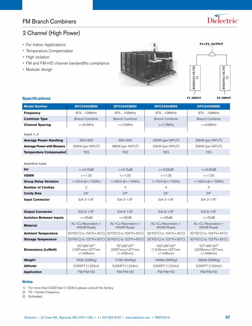
5722 Tower Road, P.O. Box 949, Raymond, ME 04071 • 207-655-8100 • 1-800-341-9678 • Fax: 207-655-8177 • www.dielectric.comDielectric • 22 Tower Rd., Raymond, ME 04071 USA • +1 207-655-8100 • www.dielectric.com • FM07/2013
FM Branch Combiners
2 Channel (High Power)
Specifications
Model Number DFC24002BR2 DFC24003BR2 DFC24004BR2 DFC24005BR2
Frequency 87.5…108MHz 87.5…108MHz 87.5…108MHz 87.5…108MHz
Combiner Type Branch Combiner Branch Combiner Branch Combiner Branch Combiner
Channel Spacing >=9.2MHz >=2.0MHz >=1.2MHz >=0.8MHz
Input 1, 2
Average Power Handling 35K/35K 35K/35K 25KW (per INPUT) 20KW (per INPUT)
Average Power with Blowers 45KW (per INPUT) 38KW (per INPUT) 33KW (per INPUT) 30KW (per INPUT)
Temperature Compensated YES YES YES YES
Insertion Loss
F02 <=0.10dB <=0.15dB <=0.25dB <=0.35dB
VSWR <=1.05 <=1.05 <=1.05 <=1.05
Group Delay Variation <=30nS @+/-150Khz <=50nS @+/-150Khz <=70nS @+/-150Khz <=160nS @+/-150Khz
Number of Cavities 2 3 4 5
Cavity Size 24" 24" 24" 24"
Input Connector EIA 3-1/8" EIA 3-1/8" EIA 3-1/8" EIA 3-1/8"
Output Connector EIA 6-1/8" EIA 6-1/8" EIA 6-1/8" EIA 6-1/8"
Isolation Between Inputs >=35dB >=35dB >=35dB >=35dB
Material AL+Cu Resonators + INVAR Roads
AL+Cu Resonators + INVAR Roads
AL+Cu Resonators + INVAR Roads
AL+Cu Resonators + INVAR Roads
Ambient Temperature 32˚F(0˚C) to 104˚F(+40˚C) 32˚F(0˚C) to 104˚F(+40˚C) 32˚F(0˚C) to 104˚F(+40˚C) 32˚F(0˚C) to 104˚F(+40˚C)
Storage Temperature 32˚F(0˚C) to 122˚F(+50˚C) 32˚F(0˚C) to 122˚F(+50˚C) 32˚F(0˚C) to 122˚F(+50˚C) 32˚F(0˚C) to 122˚F(+50˚C)
Dimensions (LxWxH)55"x66"x57"
(1397mmx1.677mm x1.448mm)
79"x66"x57" (2007mmx1.677mm
x1.448mm)
103"x66"x57" (1.616mmx1.677mm
x1.448mm)
127"x66"x57" (3226mmx1.677mm
x1.448mm)
Weight3 740lb (336Kg) 1110lb (504Kg) 1466lb (665Kg) 1820lb (826Kg)
Altitude1 5,000FT (1,524m) 5,000FT (1,524m) 5,000FT (1,524m) 5,000FT (1,524m)
Application FM/FM-HD FM/FM-HD FM/FM-HD FM/FM-HD
Notes
1) For more than 5,000 feet (1,524m), please consult the factory 2) F0 - Center Frequency3) Estimated
• For Indoor Applications• Temperature Compensated• High isolation• FM and FM-HD channel bandwidths compliance• Modular design

5822 Tower Road, P.O. Box 949, Raymond, ME 04071 • 207-655-8100 • 1-800-341-9678 • Fax: 207-655-8177 • www.dielectric.comDielectric • 22 Tower Rd., Raymond, ME 04071 USA • +1 207-655-8100 • www.dielectric.com • FM07/2013
FM Branch Combiners
3 Channel
• For Indoor Applications• Temperature Compensated• High isolation• FM and FM-HD channel bandwidths compliance• Modular design
Specifications
Model Number DFC14003BR3 DFC14004BR3 DFC14005BR3
Frequency 87.5…108MHz 87.5…108MHz 87.5…108MHz
Combiner Type Branch Combiner Branch Combiner Branch Combiner
Channel Spacing >=2.0MHz >=1.2MHz >=0.8MHz
Input 1, 2, 3
Average Power Handling 20KW (per INPUT) 15KW (per INPUT) 12KW (per INPUT)
Average Power with Blowers 25KW (per INPUT) 20KW (per INPUT) 17KW (per INPUT)
Temperature Compensated YES YES YES
Insertion Loss
F02 <=0.25dB <=0.35dB <=0.45dB
VSWR <=1.05 <=1.05 <=1.05
Group Delay Variation <=50nS @+/-150Khz <=70nS @+/-150Khz <=160nS @+/-150Khz
Number of Cavities 3 4 5
Cavity Size 14" 14" 14"
Input Connector EIA 3-1/8" EIA 3-1/8" EIA 3-1/8"
Output Connector 4-1/16" FLG 4-1/16" FLG 4-1/16" FLG
Isolation Between Inputs >=35dB >=35dB >=35dB
Material AL+Cu Resonators +INVAR Roads
AL+Cu Resonators +INVAR Roads
AL+Cu Resonators +INVAR Roads
Ambient Temperature 32˚F(0˚C) to 104˚F(+40˚C) 32˚F(0˚C) to 104˚F(+40˚C) 32˚F(0˚C) to 104˚F(+40˚C)
Storage Temperature 32˚F(0˚C) to 122˚F(+50˚C) 32˚F(0˚C) to 122˚F(+50˚C) 32˚F(0˚C) to 122˚F(+50˚C)
Dimensions (LxWxH)60"x66"x57"
(1524mmx1.677mm x1.448mm)
73"x66"x57" (1.854mmx1.677mm
x1.448mm)
107"x66"x57" (2718mmx1.677mm
x1.448mm)
Weight3 1465lb (665Kg) 1925lb (873Kg) 2385lb (1082Kg)
Altitude1 5,000FT (1,524m) 5,000FT (1,524m) 5,000FT (1,524m)
Application FM/FM-HD FM/FM-HD FM/FM-HD
Notes
1) For more than 5,000 feet (1,524m), please consult the factory 2) F0 - Center Frequency3) Estimated
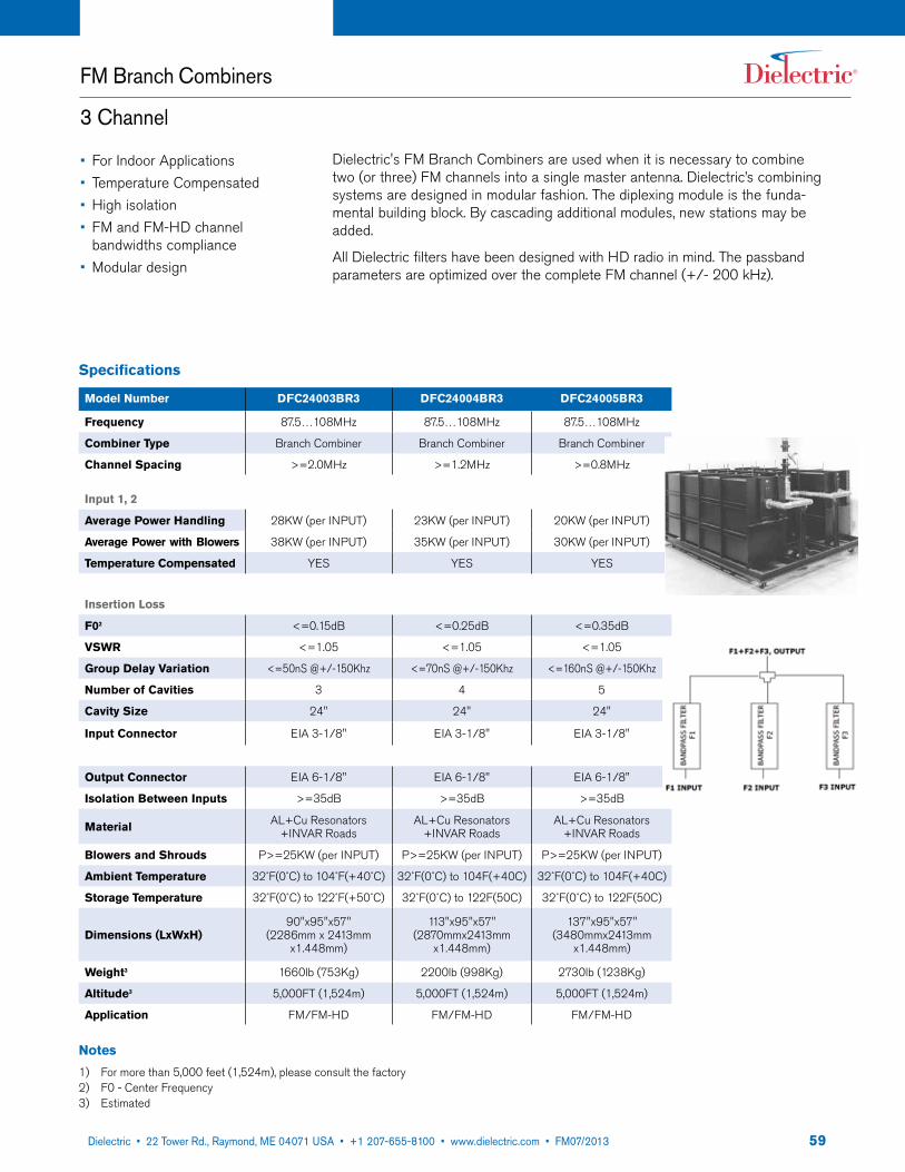
5922 Tower Road, P.O. Box 949, Raymond, ME 04071 • 207-655-8100 • 1-800-341-9678 • Fax: 207-655-8177 • www.dielectric.comDielectric • 22 Tower Rd., Raymond, ME 04071 USA • +1 207-655-8100 • www.dielectric.com • FM07/2013
Dielectric's FM Branch Combiners are used when it is necessary to combine two (or three) FM channels into a single master antenna. Dielectric’s combining systems are designed in modular fashion. The diplexing module is the funda-mental building block. By cascading additional modules, new stations may be added.
All Dielectric filters have been designed with HD radio in mind. The passband parameters are optimized over the complete FM channel (+/- 200 kHz).
FM Branch Combiners
3 Channel
Specifications
Model Number DFC24003BR3 DFC24004BR3 DFC24005BR3
Frequency 87.5…108MHz 87.5…108MHz 87.5…108MHz
Combiner Type Branch Combiner Branch Combiner Branch Combiner
Channel Spacing >=2.0MHz >=1.2MHz >=0.8MHz
Input 1, 2
Average Power Handling 28KW (per INPUT) 23KW (per INPUT) 20KW (per INPUT)
Average Power with Blowers 38KW (per INPUT) 35KW (per INPUT) 30KW (per INPUT)
Temperature Compensated YES YES YES
Insertion Loss
F02 <=0.15dB <=0.25dB <=0.35dB
VSWR <=1.05 <=1.05 <=1.05
Group Delay Variation <=50nS @+/-150Khz <=70nS @+/-150Khz <=160nS @+/-150Khz
Number of Cavities 3 4 5
Cavity Size 24" 24" 24"
Input Connector EIA 3-1/8" EIA 3-1/8" EIA 3-1/8"
Output Connector EIA 6-1/8" EIA 6-1/8" EIA 6-1/8"
Isolation Between Inputs >=35dB >=35dB >=35dB
Material AL+Cu Resonators +INVAR Roads
AL+Cu Resonators +INVAR Roads
AL+Cu Resonators +INVAR Roads
Blowers and Shrouds P>=25KW (per INPUT) P>=25KW (per INPUT) P>=25KW (per INPUT)
Ambient Temperature 32˚F(0˚C) to 104˚F(+40˚C) 32˚F(0˚C) to 104F(+40C) 32˚F(0˚C) to 104F(+40C)
Storage Temperature 32˚F(0˚C) to 122˚F(+50˚C) 32˚F(0˚C) to 122F(50C) 32˚F(0˚C) to 122F(50C)
Dimensions (LxWxH)90"x95"x57"
(2286mm x 2413mm x1.448mm)
113"x95"x57" (2870mmx2413mm
x1.448mm)
137"x95"x57" (3480mmx2413mm
x1.448mm)
Weight3 1660lb (753Kg) 2200lb (998Kg) 2730lb (1238Kg)
Altitude3 5,000FT (1,524m) 5,000FT (1,524m) 5,000FT (1,524m)
Application FM/FM-HD FM/FM-HD FM/FM-HD
Notes
1) For more than 5,000 feet (1,524m), please consult the factory 2) F0 - Center Frequency3) Estimated
• For Indoor Applications• Temperature Compensated• High isolation• FM and FM-HD channel
bandwidths compliance• Modular design

6022 Tower Road, P.O. Box 949, Raymond, ME 04071 • 207-655-8100 • 1-800-341-9678 • Fax: 207-655-8177 • www.dielectric.comDielectric • 22 Tower Rd., Raymond, ME 04071 USA • +1 207-655-8100 • www.dielectric.com • FM07/2013
FM Combiners (Manifold Type)
3 Channel
• Combines more than 3 or more stations• For Indoor Applications• Temperature Compensated• High isolation• FM and FM-HD channel bandwidths compliance• Modular design
Specifications
Model Number DFCXX00XMX
Total Average Power 140kW
Frequency 87.5…108MHz
Combiner Type MANIFOLD
Channel Spacing >=1.2MHz 6
Insertion Loss
F02 <=0.35dB4)
VSWR <=1.08
Group Delay Variation Channel Spacing Dependent
Number of Cavities 4 (OR 3) 5
Cavity Size 14" (OR 24")
Isolation between Inputs >=35dB
Output Connector 4-1/16" FLG/6-1/8" FLG
Average Power per Input Channel Spacing Dependent
Material AL+Cu Resonators +IN-VAR Roads
Ambient Temperature 32˚F(0˚C) to 104˚F(+40˚C)
Storage Temperature 32˚F(0˚C) to 122˚F(+50˚C)
Dimensions (LxWxH) Contact Factory
Weight (lbs.) Contact Factory
Altitude1 5,000FT (1,524m)
Application FM/FM-HD
Notes
1) For more than 5,000 feet (1,524m), please consult the factory 2) F0 - Center Frequency3) Optional blowers may be required for higher power 4) Varying with the cavity size and number of cavities per channel5) Depends of the channel spacing6) For less than 1.2MHz, please contact the factory

6122 Tower Road, P.O. Box 949, Raymond, ME 04071 • 207-655-8100 • 1-800-341-9678 • Fax: 207-655-8177 • www.dielectric.comDielectric • 22 Tower Rd., Raymond, ME 04071 USA • +1 207-655-8100 • www.dielectric.com • FM07/2013
FM Constant Impedance Filter/Combiner
Medium Power
• For Indoor Applications• Temperature Compensated
Specifications
Model Number DFC14003CIF DFC14004CIF DFC14005CIF
Frequency 87.5…108MHz 87.5…108MHz 87.5…108MHz
Combiner Type Constant Impedance Filter Constant Impedance Filter Constant Impedance Filter
Channel Spacing >=2.0MHz >=1.2MHz >=0.8MHz
Narrow Band Input
Average Power Handling 40kW 30kW 24kW
Average Power with Blowers 50KW (per INPUT) 40KW (per INPUT) 34KW (per INPUT)
Temperature Compensated YES YES YES
Insertion Loss
F02 <=0.25dB <=0.35dB <=0.45dB
VSWR <=1.06 <=1.06 <=1.06
Group Delay Variation <=50nS @+/-150Khz <=70nS @+/-150Khz <=160nS @+/-150Khz
Number of Cavities 3 4 5
Cavity Size 14" 14" 14"
Input Hybrid EIA 3-1/8" EIA 3-1/8" EIA 3-1/8"
Input Connector EIA1-5/8" OR EIA 3-1/8" EIA1-5/8" OR EIA 3-1/8" EIA1-5/8" OR EIA 3-1/8"
Wide Band Input
Insertion Loss <=0.1dB <=0.15dB <=0.2dB
Group Delay Variation4 <=20nS @+/-150Khz <=30nS @+/-150Khz <=100nS @+/-150Khz
VSWR <=1.07 <=1.07 <=1.07
Input Connector EIA 3-1/8" OR 4-1/16"FLG EIA 3-1/8" OR 4-1/16"FLG EIA 3-1/8" OR 4-1/16"FLG
Isolation
NB to WB >=35dB >=35dB >=35dB
WB to NB >=50dB >=55dB >=55dB
Maximum Output Power Handling 70kW 70kW 70kW
Ouput Hybrid 4-1/16" FLG 4-1/16" FLG 4-1/16" FLG
Output Connector EIA 3-1/8" OR 4-1/16"FLG EIA 3-1/8" OR 4-1/16"FLG EIA 3-1/8" OR 4-1/16"FLG
Material AL+Cu Resonators +INVAR Roads
AL+Cu Resonators +INVAR Roads
AL+Cu Resonators +INVAR Roads
Ambient Temperature 32˚F(0˚C) to 104˚F(+40˚C) 32˚F(0˚C) to 104˚F(+40˚C) 32˚F(0˚C) to 104˚F(+40˚C)
Storage Temperature 32˚F(0˚C) to 122˚F(+50˚C) 32˚F(0˚C) to 122˚F(+50˚C) 32˚F(0˚C) to 122˚F(+50˚C)
Dimensions (LxWxH)65"x43"x63"
(1.651mm x 1.092mm x 1.600mm)
84"x43"x63" (2.124mm x 1.092mm x
1.600mm)
104"x43"x63" (2.642mm x 1.092mm
x 1.600mm)
Weight3 1120Lbs 1445lb (Kg) 1766Lbs
Altitude1 5,000FT (1,524m) 5,000FT (1,524m) 5,000FT (1,524m)
Application FM/FM-HD FM/FM-HD FM/FM-HD
• High isolation• FM and FM-HD channel bandwidths compliance• Modular design
Notes
1) For more than 5,000 feet (1,524m), please consult the factory 2) F0 - Center Frequency3) Estimated4) Wide band group delay is
added to narrow band delay of upstream filter
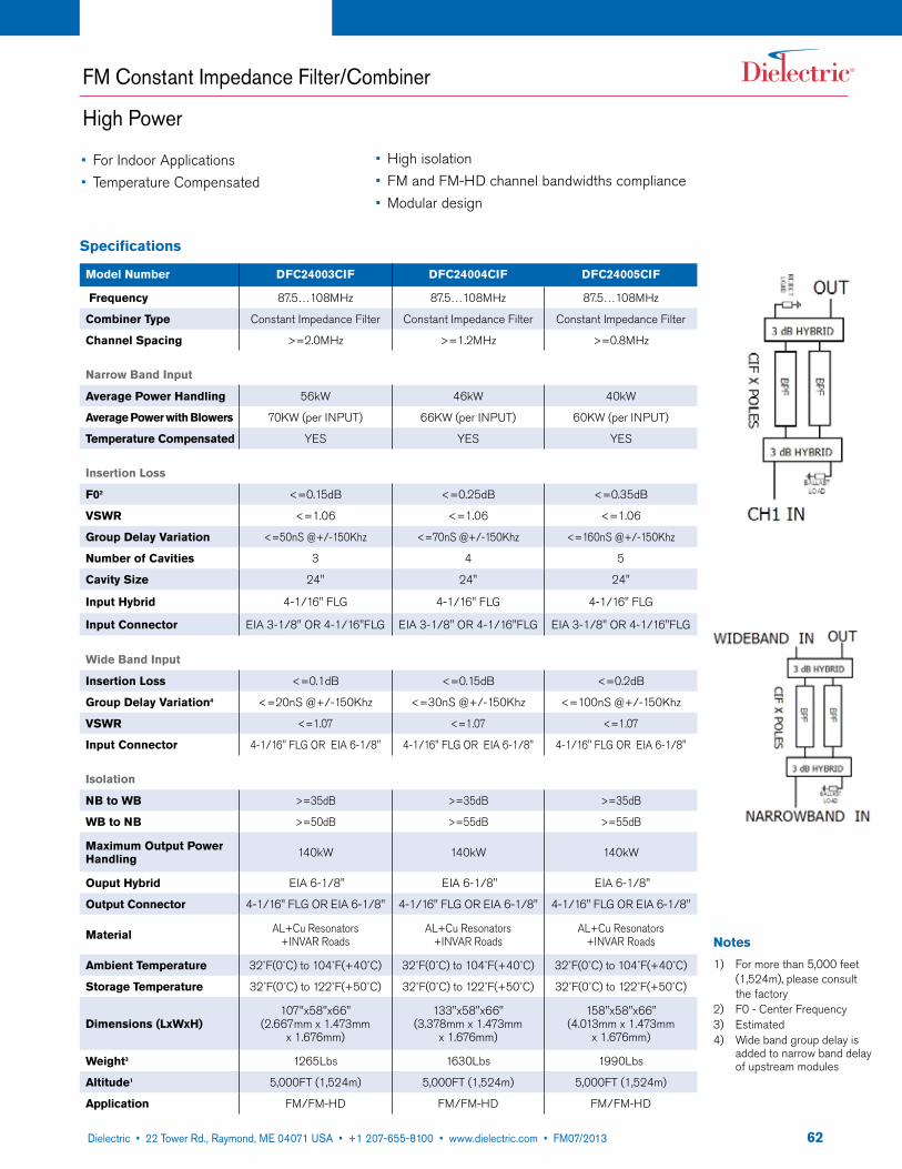
6222 Tower Road, P.O. Box 949, Raymond, ME 04071 • 207-655-8100 • 1-800-341-9678 • Fax: 207-655-8177 • www.dielectric.comDielectric • 22 Tower Rd., Raymond, ME 04071 USA • +1 207-655-8100 • www.dielectric.com • FM07/2013
FM Constant Impedance Filter/Combiner
High Power
• For Indoor Applications• Temperature Compensated
Specifications
Model Number DFC24003CIF DFC24004CIF DFC24005CIF
Frequency 87.5…108MHz 87.5…108MHz 87.5…108MHz
Combiner Type Constant Impedance Filter Constant Impedance Filter Constant Impedance Filter
Channel Spacing >=2.0MHz >=1.2MHz >=0.8MHz
Narrow Band Input
Average Power Handling 56kW 46kW 40kW
Average Power with Blowers 70KW (per INPUT) 66KW (per INPUT) 60KW (per INPUT)
Temperature Compensated YES YES YES
Insertion Loss
F02 <=0.15dB <=0.25dB <=0.35dB
VSWR <=1.06 <=1.06 <=1.06
Group Delay Variation <=50nS @+/-150Khz <=70nS @+/-150Khz <=160nS @+/-150Khz
Number of Cavities 3 4 5
Cavity Size 24" 24" 24"
Input Hybrid 4-1/16" FLG 4-1/16" FLG 4-1/16" FLG
Input Connector EIA 3-1/8" OR 4-1/16"FLG EIA 3-1/8" OR 4-1/16"FLG EIA 3-1/8" OR 4-1/16"FLG
Wide Band Input
Insertion Loss <=0.1dB <=0.15dB <=0.2dB
Group Delay Variation4 <=20nS @+/-150Khz <=30nS @+/-150Khz <=100nS @+/-150Khz
VSWR <=1.07 <=1.07 <=1.07
Input Connector 4-1/16" FLG OR EIA 6-1/8" 4-1/16" FLG OR EIA 6-1/8" 4-1/16" FLG OR EIA 6-1/8"
Isolation
NB to WB >=35dB >=35dB >=35dB
WB to NB >=50dB >=55dB >=55dB
Maximum Output Power Handling 140kW 140kW 140kW
Ouput Hybrid EIA 6-1/8" EIA 6-1/8" EIA 6-1/8"
Output Connector 4-1/16" FLG OR EIA 6-1/8" 4-1/16" FLG OR EIA 6-1/8" 4-1/16" FLG OR EIA 6-1/8"
Material AL+Cu Resonators +INVAR Roads
AL+Cu Resonators +INVAR Roads
AL+Cu Resonators +INVAR Roads
Ambient Temperature 32˚F(0˚C) to 104˚F(+40˚C) 32˚F(0˚C) to 104˚F(+40˚C) 32˚F(0˚C) to 104˚F(+40˚C)
Storage Temperature 32˚F(0˚C) to 122˚F(+50˚C) 32˚F(0˚C) to 122˚F(+50˚C) 32˚F(0˚C) to 122˚F(+50˚C)
Dimensions (LxWxH)107"x58"x66"
(2.667mm x 1.473mm x 1.676mm)
133"x58"x66" (3.378mm x 1.473mm
x 1.676mm)
158"x58"x66" (4.013mm x 1.473mm
x 1.676mm)
Weight3 1265Lbs 1630Lbs 1990Lbs
Altitude1 5,000FT (1,524m) 5,000FT (1,524m) 5,000FT (1,524m)
Application FM/FM-HD FM/FM-HD FM/FM-HD
• High isolation• FM and FM-HD channel bandwidths compliance• Modular design
Notes
1) For more than 5,000 feet (1,524m), please consult the factory 2) F0 - Center Frequency3) Estimated4) Wide band group delay is
added to narrow band delay of upstream modules

6322 Tower Road, P.O. Box 949, Raymond, ME 04071 • 207-655-8100 • 1-800-341-9678 • Fax: 207-655-8177 • www.dielectric.comDielectric • 22 Tower Rd., Raymond, ME 04071 USA • +1 207-655-8100 • www.dielectric.com • FM07/2013
FM Constant Impedance Filter/Combiner
Very High Power
• For Indoor Applications• Temperature Compensated
• High isolation• FM and FM-HD channel bandwidths compliance• Modular design
Specifications
Model Number DFC24003CIF-H DFC24004CIF-H DFC24005CIF-H
Frequency 87.5…108MHz 87.5…108MHz 87.5…108MHz
Combiner Type Constant Impedance Filter Constant Impedance Filter Constant Impedance Filter
Channel Spacing >=2.0MHz >=1.2MHz >=0.8MHz
Narrow Band Input
Average Power Handling 56kW 46kW 40kW
Average Power with Blowers P>=70KW (per INPUT) P>=66KW (per INPUT) P>=60KW (per INPUT)
Temperature Compensated YES YES YES
Insertion Loss
F02 <=0.15dB <=0.25dB <=0.35dB
VSWR <=1.06 <=1.06 <=1.06
Group Delay Variation <=50nS @+/-150Khz <=70nS @+/-150Khz <=160nS @+/-150Khz
Number of Cavities 3 4 5
Cavity Size 24" 24" 24"
Input Hybrid EIA 6-1/8" EIA 6-1/8" EIA 6-1/8"
Input Connector 4-1/16" FLG OR EIA 6-1/8" 4-1/16" FLG OR EIA 6-1/8" 4-1/16" FLG OR EIA 6-1/8"
Wide Band Input
Insertion Loss <=0.1dB <=0.15dB <=0.2dB
Group Delay Variation4 <=20nS @+/-150Khz <=20nS @+/-150Khz <=20nS @+/-150Khz
VSWR <=1.07 <=1.07 <=1.07
Input Connector EIA 6-1/8" OR EIA 9-3/16" EIA 6-1/8" OR EIA 9-3/16" EIA 6-1/8" OR EIA 9-3/16"
Isolation
NB to WB >=35dB >=35dB >=35dB
WB to NB >=50dB >=55dB >=55dB
Maximum Output Power Handling 290kW 290kW 290kW
Ouput Hybrid EIA 9-3/16" EIA 9-3/16" EIA 9-3/16"
Output Connector EIA 6-1/8" OR EIA 9-3/16" EIA 6-1/8" OR EIA 9-3/16" EIA 6-1/8" OR EIA 9-3/16"
Material AL+Cu Resonators +INVAR Roads
AL+Cu Resonators +INVAR Roads
AL+Cu Resonators +INVAR Roads
Ambient Temperature 32˚F(0˚C) to 104˚F(+40˚C) 32˚F(0˚C) to 104˚F(+40˚C) 32˚F(0˚C) to 104˚F(+40˚C)
Storage Temperature 32˚F(0˚C) to 122˚F(+50˚C) 32˚F(0˚C) to 122˚F(+50˚C) 32˚F(0˚C) to 122˚F(+50˚C)
Dimensions (LxWxH)112"x58"x70"
(2.845mm x 1.473mm x 1.778mm)
138"x58"x70" (3.505mm x 1.473mm
x 1.778mm)
163"x58"x70" (4.140mm x 1.473mm
x 1.778mm)
Weight3 1295Lbs 1660Lbs 2020Lbs
Altitude1 5,000FT (1,524m) 5,000FT (1,524m) 5,000FT (1,524m)
Application FM/FM-HD FM/FM-HD FM/FM-HD
Notes
1) For more than 5,000 feet (1,524m), please consult the factory 2) F0 - Center Frequency3) Estimated4) Wide band group delay is
added to narrow band delay of upstream modules
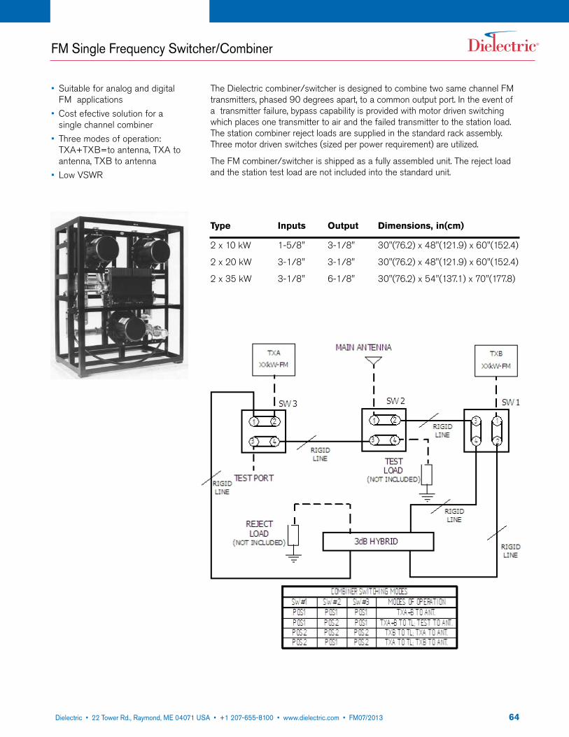
6422 Tower Road, P.O. Box 949, Raymond, ME 04071 • 207-655-8100 • 1-800-341-9678 • Fax: 207-655-8177 • www.dielectric.comDielectric • 22 Tower Rd., Raymond, ME 04071 USA • +1 207-655-8100 • www.dielectric.com • FM07/2013
The Dielectric combiner/switcher is designed to combine two same channel FM transmitters, phased 90 degrees apart, to a common output port. In the event of a transmitter failure, bypass capability is provided with motor driven switching which places one transmitter to air and the failed transmitter to the station load. The station combiner reject loads are supplied in the standard rack assembly. Three motor driven switches (sized per power requirement) are utilized.
The FM combiner/switcher is shipped as a fully assembled unit. The reject load and the station test load are not included into the standard unit.
Type Inputs Output Dimensions, in(cm)
2 x 10 kW 1-5/8" 3-1/8" 30"(76.2) x 48"(121.9) x 60"(152.4)
2 x 20 kW 3-1/8" 3-1/8" 30"(76.2) x 48"(121.9) x 60"(152.4)
2 x 35 kW 3-1/8" 6-1/8" 30"(76.2) x 54"(137.1) x 70"(177.8)
FM Single Frequency Switcher/Combiner
• Suitable for analog and digital FM applications
• Cost efective solution for a single channel combiner
• Three modes of operation: TxA+TxB=to antenna, TxA to antenna, TxB to antenna
• Low VSWR

6522 Tower Road, P.O. Box 949, Raymond, ME 04071 • 207-655-8100 • 1-800-341-9678 • Fax: 207-655-8177 • www.dielectric.comDielectric • 22 Tower Rd., Raymond, ME 04071 USA • +1 207-655-8100 • www.dielectric.com • FM07/2013
Specifications
Model Number CU13SW20 CU34SW50 CU36SW80 CU46SW130
Total Average Power 20kW 50KW 80KW 130kW
Frequency 87.5…108MHz 87.5…108MHz 87.5…108MHz 87.5…108MHz
Combiner Type Switcher Combiner Switcher Combiner Switcher Combiner Switcher Combiner
Channel Spacing
Same Channel Same Channel Same Channel Same Channel
A, B Input
Average Power Handling 10K, 10K 25K, 25K 40K, 40K 65K, 65K
Insertion Loss <=0.15dB <=0.15dB <=0.15dB <=0.15dB
Isolation Between Inputs >=32dB >=32dB >=32dB >=32dB
VSWR <1.05 <1.05 <1.05 <1.05
Connector EIA 3-1/8" EIA 3-1/8" EIA 3-1/8" FLG. 4-1/16"
Output Connector
Isolation Between Inputs >=32dB >=32dB >=32dB >=32dB
Connector EIA 3-1/8" FLG. 4-1/16" EIA 6-1/8" EIA 6-1/8"
Control Voltage 12VDC or 24VDC 12VDC or 24VDC 12VDC or 24VDC 12VDC or 24VDC
Inerlocks DPDT EACH POSITION DPDT EACH POSITION DPDT EACH POSITION DPDT EACH POSITION
Ambient Temperature 32˚F(0˚C) to 114˚F(+45˚C) 32˚F(0˚C) to 114˚F(+45˚C) 32˚F(0˚C) to 114˚F(+45˚C) 32˚F(0˚C) to 114˚F(+45˚C)
Storage Temperature 32˚F(0˚C) to 122˚F(50˚C) 32˚F(0˚C) to 122˚F(50˚C) 32˚F(0˚C) to 122˚F(50˚C) 32˚F(0˚C) to 122˚F(50˚C)
Ambient/Storage Humidity 0-98% non condensing 0-98% non condensing 0-98% non condensing 0-98% non condensing
AC Operating Voltage 115VAC (230VAC) 50/60Hz 115VAC (230VAC) 50/60Hz 115VAC (230VAC) 50/60Hz 115VAC (230VAC) 50/60Hz
Dimensions (LxWxH) 48"x34"x60" (1.2mx0.9mx1.5m)
48"x34"x60" (1.2mx0.9mx1.5m)
54"x38"x70" (1.4mx1.0mx1.8m)
54"x38"x70" (1.4mx1.0mx1.8m)
Weight3 430lbs (195kg) 480lbs (218kg) 765lbs (347kg) 800lbs (363kg)
Altitude1 5.000FT (1,524m) 5.000FT (1,524m) 5.000FT (1,524m) 5.000FT (1,524m)
Application FM/FM-HD FM/FM-HD FM/FM-HD FM/FM-HD
Notes
1) At ambient 104˚F(40˚C), sea level, 0 PSIG; For higher power values, please contact the factory 2) Standard as 3dB combiner type; Contact factory for other combined levels. 3) For more than 5,000FT (1,524m), please consult the factory
FM Single Frequency Switcher/Combiner

6622 Tower Road, P.O. Box 949, Raymond, ME 04071 • 207-655-8100 • 1-800-341-9678 • Fax: 207-655-8177 • www.dielectric.comDielectric • 22 Tower Rd., Raymond, ME 04071 USA • +1 207-655-8100 • www.dielectric.com • FM07/2013
HD Radio High Level Analog-Digital Combiner/Injector
Dielectric's High Level HD Radio Combiner/Injector provides another degree of freedom to the broadcaster. It allows a digital signal to be added to an existing run of line, without the addition of a new feed line or antenna. The units were designed with ease of installation in mind. Simply install the unit in place of a straight section of transmission line in the transmitter room. The aluminum con-struction is such that the weight of the unit is comparable to that of the line sec-tion it replaces.
Specifications
Frequency Range: 88 - 108 MHzImpedance: 50 ohmsI/O Ports: EIA flangedVSWR: 1.05:1 or better when terminated in a matched loadInsertion Loss: <0.1 dB or lessIsolation: minimum >45 dB Group Delay Variation: <10 nS over any 400 kHz bandMounting: Any PositionFinish: Black PaintCatalog No: DC-HDR- () -Size from Chart () -Type chart Example: DCR-HDR-A-1 1 5/8" Combiner with 10 dB coupling
Size A B C DAnalog Port 1 5/8" 3 1/8" 4 1/16" 6 1/8" Max. Total Power 12 40 50 70Type 1 2 3 4Coupling Factor 10 dB 9 dB 8 dB Custom
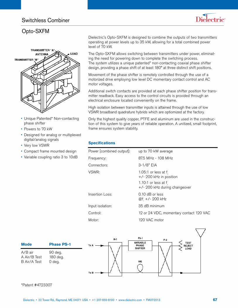
6722 Tower Road, P.O. Box 949, Raymond, ME 04071 • 207-655-8100 • 1-800-341-9678 • Fax: 207-655-8177 • www.dielectric.comDielectric • 22 Tower Rd., Raymond, ME 04071 USA • +1 207-655-8100 • www.dielectric.com • FM07/2013
Switchless Combiner
Opto-SXFMDielectric's Opto-SxFM is designed to combine the outputs of two transmitters operating at power levels up to 35 kW, allowing for a total combined power level of 70 kW.
The Opto-SxFM allows switching between transmitters under power, eliminat-ing the need for powering down to complete the switching process. The system utilizes a unique patented* non-contacting coaxial phase shifter design, providing a phase shift of at least 180° at three distinct shift positions.
Movement of the phase shifter is remotely controlled through the use of a motorized drive employing low level DC momentary contact control and AC motor voltages.
Additional switch contacts are provided at each phase shifter position for trans-mitter readback. Easy access to the control circuits is provided through an electrical enclosure located conveniently on the frame.
High isolation between transmitter inputs is attained through the use of low VSWR broadband quadrature hybrids which are optiomized at the factory.
Only the highest quality copper, PTFE and aluminum are used in the construc-tion of this system to give years of reliable operation. A unitized, small footprint, frame ensures system stability.
Specifications
Power [combined output]: up to 70 kW average
Frequency: 87.5 MHz - 108 MHz
Connectors: 3-1/8" EIA
VSWR: 1.05:1 or less at fc
+/- 200 kHz in position 1.10:1 or less at f
c
+/- 200 kHz during changeover
Insertion Loss: 0.10 dB or less @f
c +/- 200 kHz
Input isolation: 35 dB minimum
Control: 12 or 24 VDC, momentary contact 120 VAC
Motor: 120 VAC motor
Mode Phase PS-1
A/B air 90 deg.A Air/B Test 180 deg.B Air/A Test 0 deg.
*Patent #4723307
• Unique Patented* Non-contacting phase shifter
• Powers to 70 kW• Designed for analog or multiplexed
digital/analog signals• Very low VSWR• Compact frame mounted design• Variable coupling ratio 3 to 10dB
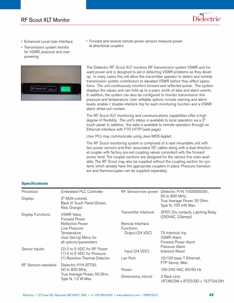
6822 Tower Road, P.O. Box 949, Raymond, ME 04071 • 207-655-8100 • 1-800-341-9678 • Fax: 207-655-8177 • www.dielectric.comDielectric • 22 Tower Rd., Raymond, ME 04071 USA • +1 207-655-8100 • www.dielectric.com • FM07/2013
RF Scout XLT Monitor
The Dielectric RF Scout xLT monitors RF transmission system VSWR and for-ward power and is designed to aid in detecting VSWR problems as they devel-op. In many cases this will allow the transmitter operator to detect and remedy transmission system contributors to elevated VSWR before they affect opera-tions. The unit continuously monitors forward and reflected power. The system displays the values and can hold up to a years worth of data and alarm events. In addition, the system can also be configured to monitor transmission line pressure and temperature. User settable options include warning and alarm levels, enable / disable interlock trip for each monitoring function and a VSWR alarm strike-out number.
The RF Scout xLT monitoring and communications capabilities offer a high degree of flexibility. The unit’s status is available to local operators via a 3" touch panel. In addition, the data is available to remote operators through an Ethernet interface with FTP, HTTP (web page).
User PCs may communicate using Java WEB Applet.
The RF Scout monitoring system is comprised of a rack mountable unit with two power sensors and their associated 25’ cables along with a dual direction-al coupler with factory pre-set coupling values consistent with the forward power level. The coupler sections are designed for the various line sizes avail-able. The RF Scout may also be supplied without the coupling section for sys-tems which already have the appropriate couplers in place. Pressure transduc-ers and thermocouples can be supplied separately.
• Enhanced Local User Interface• Transmission system monitor
for VSWR, pressure and over- powering
• Forward and reverse remote power sensors measure power at directional couplers
Specifications
Processor: Embedded PLC Controller
Display: 3" Multi-colored, Back lit Touch Panel (Green, Red, Orange)
Display Functions: VSWR Value Forward Power Reflective Power Line Pressure Temperature User Set-Up Menu for all options/parameters
Sensor Inputs: (2) 0 to 5 VDC for RF Power (1) 0 to 5 VDC for Pressure (1) Resistive Thermal Detector
RF Sensors-standard: Dielectric P/N 97730, 50 to 800 MHz, True Average Power, 50 Ohm, Type N, 1.0 W Max.
RF Sensors-low power: Dielectric P/N 11000005351, 50 to 800 MHz, True Average Power, 50 Ohm, Type N, 100 mW Max.
Transmitter Interlock: SPDT; Dry contacts, Latching Relay (250VAC, 2.5amps)
Remote Interface Functions: Output (24 VDC) Tx Interlock trip
VSWR Alarm Forward Power Alarm Pressure Alarm
Input (24 VDC) Interlock Reset
Lan Port: 10/100 base T Ethernet, FTP Server, Web
Power: 100-240 VAC, 60/50 Hz
Dimensions, in(cm): 2 Rack Unit, 19"(48.2)W x 8"(20.3)D x 13.5"(34.3)H
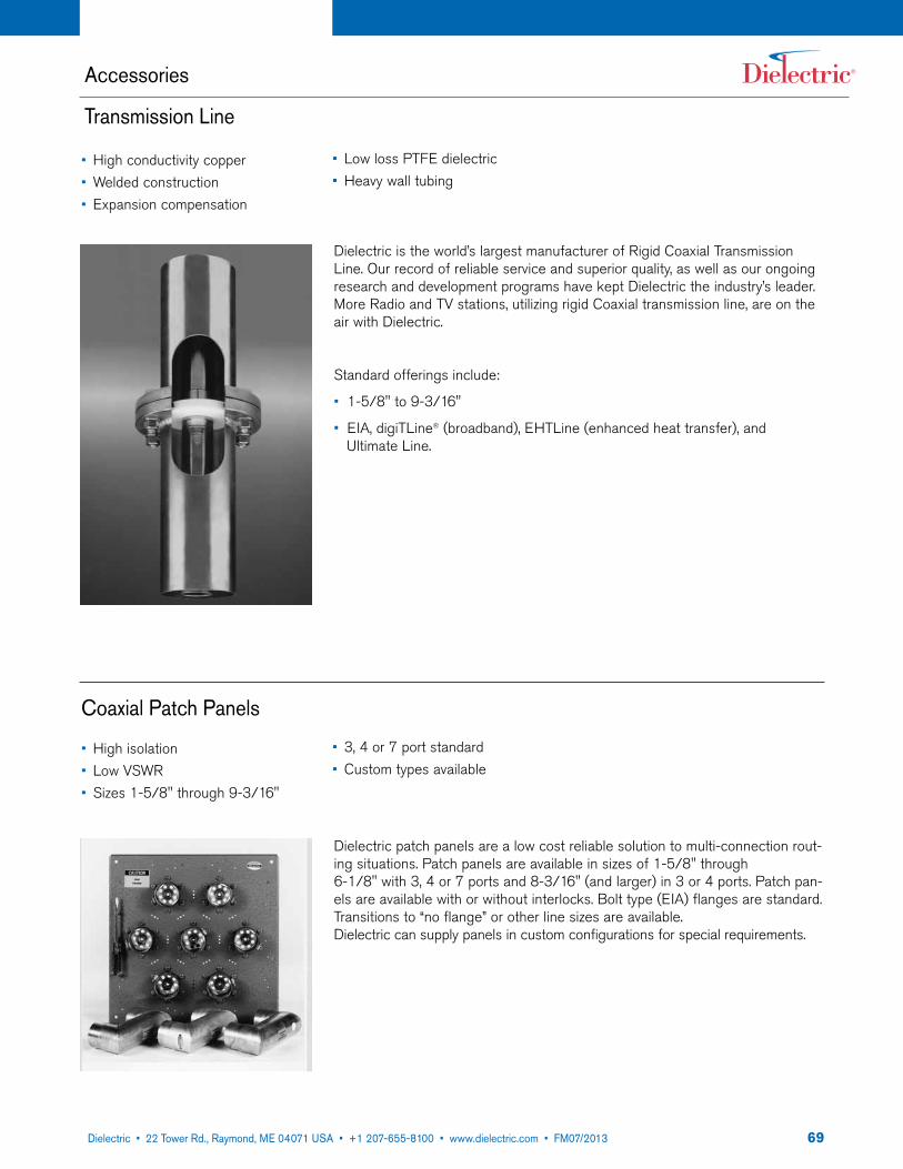
6922 Tower Road, P.O. Box 949, Raymond, ME 04071 • 207-655-8100 • 1-800-341-9678 • Fax: 207-655-8177 • www.dielectric.comDielectric • 22 Tower Rd., Raymond, ME 04071 USA • +1 207-655-8100 • www.dielectric.com • FM07/2013
Accessories
Transmission Line
Coaxial Patch Panels
Dielectric is the world’s largest manufacturer of Rigid Coaxial Transmission Line. Our record of reliable service and superior quality, as well as our ongoing research and development programs have kept Dielectric the industry’s leader. More Radio and TV stations, utilizing rigid Coaxial transmission line, are on the air with Dielectric.
Standard offerings include:
• 1-5/8" to 9-3/16"
• EIA, digiTLine® (broadband), EHTLine (enhanced heat transfer), and Ultimate Line.
• High conductivity copper• Welded construction• Expansion compensation
• High isolation• Low VSWR• Sizes 1-5/8" through 9-3/16"
Dielectric patch panels are a low cost reliable solution to multi-connection rout-ing situations. Patch panels are available in sizes of 1-5/8" through 6-1/8" with 3, 4 or 7 ports and 8-3/16" (and larger) in 3 or 4 ports. Patch pan-els are available with or without interlocks. Bolt type (EIA) flanges are standard. Transitions to “no flange” or other line sizes are available. Dielectric can supply panels in custom configurations for special requirements.
• Low loss PTFE dielectric• Heavy wall tubing
• 3, 4 or 7 port standard• Custom types available
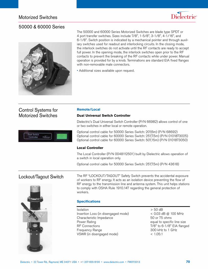
7022 Tower Road, P.O. Box 949, Raymond, ME 04071 • 207-655-8100 • 1-800-341-9678 • Fax: 207-655-8177 • www.dielectric.comDielectric • 22 Tower Rd., Raymond, ME 04071 USA • +1 207-655-8100 • www.dielectric.com • FM07/2013
Motorized Switches
50000 & 60000 Series
Control Systems for Motorized Switches
Lockout/Tagout Switch
The 50000 and 60000 Series Motorized Switches are blade type SPDT or 4 port transfer switches. Sizes include 7/8", 1-5/8", 3-1/8", 4-1/16", and 6-1/8". Switch position is indicated by a mechanical pointer and through auxil-iary switches used for readout and interlocking circuits. In the closing mode, the interlock switches do not activate until the RF contacts are ready to accept full power. In the opening mode, the interlock switches open prior to the RF contacts to prevent the breaking of the RF contacts while under power. Manual operation is provided for by a knob. Terminations are standard EIA fixed flanges with non-removable male connectors.
• Additional sizes available upon request.
Remote/Local
Dual Universal Switch Controller
Dielectric's Dual Universal Switch Controller (P/N 66982) allows control of one or two switches in either local or remote operation.
Optional control cable for 50000 Series Switch: 20'(6m) (P/N 68692) Optional control cable for 60000 Series Switch: 25'(7.5m) (P/N 0101873025) Optional control cable for 60000 Series Switch: 50'(15m) (P/N 0101873050)
Local Controller
The Local Controller (P/N 0048112501) built by Dielectric allows operation of a switch in local operation only.
Optional control cable for 50000 Series Switch: 25'(7.5m) (P/N 43618)
The RF “LOCKOUT/TAGOUT” Safety Switch prevents the accidental exposure of workers to RF energy. It acts as an isolation device preventing the flow of RF energy to the transmission line and antenna system. This unit helps stations to comply with OSHA Rule 1910.147 regarding the general protection of workers.
Specifications
Isolation > 50 dBInsertion Loss (in disengaged mode) < 0.03 dB @ 100 MHzCharacteristic Impedance 50 or 75 ohmsPower Rating equal to specific line sizeRF Connections 7/8" to 6-1/8" EIA flangedFrequency Range 300 kHz to 1 GHzVSWR (in disengaged mode) < 1.05:1

7122 Tower Road, P.O. Box 949, Raymond, ME 04071 • 207-655-8100 • 1-800-341-9678 • Fax: 207-655-8177 • www.dielectric.comDielectric • 22 Tower Rd., Raymond, ME 04071 USA • +1 207-655-8100 • www.dielectric.com • FM07/2013
Air Dryers for Transmission Lines
• Adjustable system pressure allows for altitude compensation to assure peak efficiency at any ele-vation
• Self-regenerating twin tower dry-ing system for years of trouble free operation.
Dielectric's automatic, self-contained compressor dehydrators, Models 200, 600, 850 and 1200 provide a dry air source for a variety of small volume appli-cations. These compact units are the ideal choice for low volume dry air require-ments. Each of these models is available in four alarm/output pressure configu-rations and in 115V/60-50 Hz or 220V/60-50 Hz to provide optimum capabili-ties for all applications.
Unit Capabilities
Line Size 1-5/8" 3-1/8" 4-1/16" 6-1/8"Model ft (m) ft (m) ft (m) ft (m)
TLS 300 5000 (1525) 1650 (1500) 850 (260)
TLS 1000 5000 (1525) 3000 (915) 1500 (460)
200C 5000 (1525) 850 (260)
600C 3500 (1070) 2100 (640) 900 (275)
850C 5000 (1525) 3000 (915) 1500 (460)

7222 Tower Road, P.O. Box 949, Raymond, ME 04071 • 207-655-8100 • 1-800-341-9678 • Fax: 207-655-8177 • www.dielectric.comDielectric • 22 Tower Rd., Raymond, ME 04071 USA • +1 207-655-8100 • www.dielectric.com • FM07/2013

Dielectric products are represented in 90 countries around the world. With the rapid expansion of communications, Dielectric is positioned to service the broadcast needs of small and large stations, DTV and NTSC, FM and specialty RF systems, complete systems and components.
Specifications subject to change without notice.
Abu DhabiAngolaArgentinaAustraliaAustriaBelgiumBelizeBeninBotswanaBrazilCanadaChadChileChinaColombiaCosta RicaDenmarkDominican RepublicEcuadorEgyptElboniaEl SalvadorEnglandEthiopiaFinlandFranceGermanyGhanaGreeceGreenlandGuam
GuatemalaHong KongIcelandIndiaIndonesiaIrelandIsraelItalyJapanJordanKoreaKuwaitLebanonLiberiaMadagascarMalaysiaMaliMaltaMauritaniaMauritiusMexicoMongoliaMoroccoNepalNetherlandsNew ZealandNicaraguaNigeriaNorwayOmanPakistan
Papua New GuineaPeruPhilippinesPolandPortugalPuerto RicoQatarRomaniaRussiaSaipanSao TomeSaudi ArabiaSingaporeSouth AfricaSpainSri LankaSwedenSwitzerlandSyriaTaiwanThailandTogoTrinidadUgandaUnited StatesVenezuelaVietnamYemenZambiaZimbabwe
Global Presence