Radiation of electromagnetic waves - Shenzhen Universitycms.szu.edu.cn/emc/PPT/11 Antennas and...
129
Radiation of electromagnetic waves
Transcript of Radiation of electromagnetic waves - Shenzhen Universitycms.szu.edu.cn/emc/PPT/11 Antennas and...

Radiation of electromagnetic waves
Outline
IntroductionReview of basic antenna typesRadiation pattern gain polarizationEquivalent circuit amp radiation efficiencySmart antennasSome theorySummary
Antenna purpose
Transformation of a guided EM wave in transmission line (waveguide) into a freely propagating EM wave in space (or vice versa) with specified directional characteristics
Transformation from time-function in one-dimensional space into time-function in three dimensional space The specific form of the radiated wave is defined by the antenna structure and the environment
Space wave
Guided wave
Antenna functions
Transmission linePower transport medium - must avoid power reflections otherwise use matching devices
RadiatorMust radiate efficiently ndash must be of a size comparable with the half-wavelength
ResonatorUnavoidable - for broadband applications resonances must be attenuated
Monopole (dipole over plane)Low-QBroadband
High-QNarrowband
If there is an inhomogeneity (obstacle) a reflected wave standing wave amp higher field modes appearWith pure standing wave the energy is stored and oscillates from entirely electric to entirely magnetic and backModel a resonator with high Q = (energy stored) (energy lost) per cycle as in LC circuits Kraus p2
Smooth transition region
Uniform wave traveling along the line
Outline
IntroductionReview of basic antenna types Radiation pattern gain polarizationEquivalent circuit amp radiation efficiencySmart antennasSome theorySummary
Antennas for laptop applications
Source D Liu et al Developing integrated antenna subsystems for laptop computers IBM J RES amp DEV VOL 47 NO 23 MARCHMAY 2003 p 355-367
Patch and slot antennas derived from printed-circuit and micro-strip technologies Ceramic chip antennas are typically helical or inverted-F (INF) antennas or variations of these two types with high dielectric loading to reduce the antenna size
Source D Liu et al Developing integrated antenna subsystems for laptop computers IBM J RES amp DEV VOL 47 NO 23 MARCHMAY 2003 p 355-367
Slot amp INF antennasSlot antenna a slot is cut from a large (relative to the slot length) metal plate
The center conductor of the feeding coaxial cable is connected to one side of the slot and the outside conductor of the cable - to the other side of the slot
The slot length is some (λ2) for the slot antenna and (λ4) long for the INF antenna The slot and INF antennas behave similarly
The slot antenna can be considered as a loaded version of the INF antenna The load is a quarter-wavelength stub ie a narrowband device When the feed point is moved to the short-circuited end of the slot (or INF) antenna the impedance decreases When it is moved to the slot center (or open end of the INF antenna) the impedance increases
Example double-layer printed Yagi antenna
Source N Gregorieva
Note no galvanic contact with the director
Patch and slot antennas are Cheap and easy to fabricate and to mountSuited for integration Light and mechanically robustHave low cross-polarizationLow-profile - widely used in antenna arrays
bull spacecrafts satellites missiles cars and other mobile applications
Aperture-antenna
Note The aperture concept is applicable also to wired antennas For instance the max effective aperture of linear λ2 wavelength dipole antenna is λ28
EM wave
Power absorbed P [watt]
Power density PFD [wm2]
Effective aperture A[m2]
A = APFD
Aperture antennas derived from waveguide technology (circular rectangular)Can transfer high power (magnetrons klystrons)Above few GHzWill be explored inprace during the school
Leaky-wave antennas
Derived from millimeter-wave guides (dielectric guides microstrip lines coplanar and slot lines) For frequencies gt 30 GHz including infrared Subject of intensive study
Note Periodical discontinuities near the end of the guide lead to substantial radiation leakage (radiation from the dielectric surface)
Source adapted from N Gregorieva
Reflector antennas
Reflectors are used to concentrate flux of EM energy radiated received or to change its direction Usually they are parabolic (paraboloidal)
The first parabolic (cylinder) reflector antenna was used by Heinrich Hertz in 1888
Large reflectors have high gain and directivity Are not easy to fabricateAre not mechanically robustTypical applications radio telescopes satellite telecommunications
Source adapted from N Gregorieva
Planar reflectors
Uda-Yagi Log-periodic antennas
d
2d
Intended reflector antenna allows maintaining radio link in non-LOS conditions (avoiding propagation obstacles)Unintended antennas create interference
Paraboloidal reflectors
Front feed Cassegrain feed
The largest radio telescopes
bull Max Plank Instituumlt fuumlr Radioastronomie radio telescope Effelsberg (Germany) 100-m paraboloidal reflectorThe Green Bank Telescope (the National Radio Astronomy Observatory) ndashparaboloid of aperture 100 m
Source adapted from N Gregorieva
The Arecibo Observatory Antenna System
The worldrsquos largest single radio telescope
3048-m spherical reflector National Astronomy and Ionosphere Center (USA) Arecibo Puerto Rico
The Arecibo Radio Telescope
[Sky amp Telescope Feb 1997 p 29]
Lens antennas
Source Kraus p382 N Gregorieva
Lenses play a similar role to that of reflectors in reflector antennas they collimate divergent energy Often preferred to reflectors at frequencies gt 100 GHz
Outline
IntroductionReview of basic antenna types Radiation pattern gain polarizationEquivalent circuit amp radiation efficiencySmart antennasSome theorySummary
Radiation pattern
The radiation pattern of antenna is a representation (pictorial or mathematical) of the distribution of the power out-flowing (radiated) from the antenna (in the case of transmitting antenna) or inflowing (received) to the antenna (in the case of receiving antenna) as a function of direction angles from the antenna
Antenna radiation pattern (antenna pattern) bull is defined for large distances from the antenna where the spatial
(angular) distribution of the radiated power does not depend on the distance from the radiation source
bull is independent on the power flow direction it is the same when the antenna is used to transmit and when it is used to receive radio waves
bull is usually different for different frequencies and different polarizations of radio wave radiated received
Power pattern vs Field pattern
The power pattern is the measured (calculated) and plotted received power |P(θ ϕ)| at a constant (large) distance from the antenna The amplitude field pattern is the measured (calculated) and plotted electric (magnetic) field intensity |E(θ ϕ)| or |H(θ ϕ)| at a constant (large) distance from the antenna
Power or field-strength meter
Antenna under test
Turntable
Generator
Auxiliary antenna
Large distance
The power pattern and the field patterns are inter-relatedP(θ ϕ) = (1η)|E(θ ϕ)|2 = η|H(θ ϕ)|2
P = powerE = electrical field component vectorH = magnetic field component vectorη
= 377 ohm (free-space plane wave impedance)
Normalized pattern
Usually the pattern describes the normalized field (power) values with respect to the maximum value
Note The power pattern and the amplitude field pattern are the same when computed and when plotted in dB
3-D pattern
Antenna radiation pattern is 3-dimensionalThe 3-D plot of antenna pattern assumes both angles θ and ϕ varying which is difficult to produce and to interpret
3-D pattern
Source NK Nikolova
2-D pattern
Two 2-D patterns
Usually the antenna pattern is presented as a 2-D plot with only one of the direction angles θ or ϕ variesIt is an intersection of the 3-D one with a given plane
usually it is a θ = const plane or a ϕ= const plane that contains the patternrsquos maximum
Source NK Nikolova
Example a short dipole on z-axis
Source NK Nikolova
Principal patterns
Principal patterns are the 2-D patterns of linearly polarized antennas measured in 2 planes
1 the E-plane a plane parallel to the E vector and containing the direction of maximum radiation and
2 the H-plane a plane parallel to the H vector orthogonal to the E-plane and containing the direction of maximum radiation Source NK Nikolova
Example
Source NK Nikolova
Antenna Mask (Example 1)
Typical relative directivity- mask of receiving antenna (Yagi ant TV dcm waves)
[CCIR doc 11645 17-Oct 1989)-20
-15
-10
-5
0
-180
-120 -6
0 0 60 120
180
Azimith angle degrees
Rel
ativ
e ga
in d
B
Antenna Mask (Example 2)
-50
-40
-30
-20
-10
0
01 1 10 100
PhiPhi0
Rela
tive
gain
(dB)
RR1998 APS30 Fig9
COPOLAR
CROSSPOLAR
Reference pattern for co-polar and cross-polar components for satellite transmitting antennas in Regions 1 and 3 (Broadcasting ~12 GHz)
0dB
-3dBPhi
Isotropic antenna
Isotropic antenna or isotropic radiator is a hypothetical (not physically realizable) concept used as a useful reference to describe real antennas Isotropic antenna radiates equally in all directions
Its radiation pattern is represented by a sphere whose center coincides with the location of the isotropic radiator
Source NK Nikolova
Directional antenna
Directional antenna is an antenna which radiates (or receives) much more power in (or from) some directions than in (or from) others
Note Usually this term is applied to antennas whose directivity is much higher than that of a half-wavelength dipole
Source NK Nikolova
Omnidirectional antenna
An antenna which has a non-directional pattern in a plane
It is usually directional in other planes
Source NK Nikolova
Pattern lobes
Source NK Nikolova
Pattern lobe is a portion of the radiation pattern with a local maximum
Lobes are classified as major minor side lobes back lobes
Pattern lobes and beam widths
Source NK Nikolova
Beamwidth
Half-power beamwidth (HPBW) is the angle between two vectors from the patternrsquos origin to the points of the major lobe where the radiation intensity is half its maximum
Often used to describe the antenna resolution propertiesImportant in radar technology radioastronomy etc
First-null beamwidth (FNBW) is the angle between two vectors originating at the patternrsquos origin and tangent to the main beam at its base
Often FNBW asymp 2HPBW
Example
Source NK Nikolova
Anisotropic sources gainEvery real antenna radiates more energy in some directions than in others (ie has directional properties)Idealized example of directional antenna the radiated energy is concentrated in the yellow region (cone) Directive antenna gain the power flux density is increased by (roughly) the inverse ratio of the yellow area and the total surface of the isotropic sphere
Gain in the field intensity may also be considered - it is equal to the square root of the power gain
Isotropic sphere
Antenna gain measurement
Antenna Gain = (PPo ) S=S0
Actual antenna
P = Power delivered to the actual antenna
S = Power received
(the same in both steps)
Measuring equipment
Step 2 substitution
Reference antenna
Po = Power delivered to the reference
antenna
S0 = Power received
(the same in both steps)
Measuring equipment
Step 1 reference
Antenna Gains Gi Gd
Unless otherwise specified the gain refers to the direction of maximum radiation Gain is a dimension-less factor related to power and usually expressed in decibelsGi ldquoIsotropic Power Gainrdquo ndash theoretical concept the reference antenna is isotropicGd - the reference antenna is a half-wave dipole
Typical Gain and Beamwidth
Type of antenna Gi [dB] BeamW
Isotropic 0 3600x3600
Half-wave Dipole 2 3600x1200
Helix (10 turn) 14 350x350
Small dish 16 300x300
Large dish 45 10x10
Antenna gain and effective area
Measure of the effective absorption area presented by an antenna to an incident plane wave Depends on the antenna gain and wavelength2
2( ) [m ]4eA Gλη θ ϕπ
=
Aperture efficiency ηa = Ae AA physical area of antennarsquos aperture square meters
Power Transfer in Free Space
λ wavelength [m]PR power available at the receiving antenna PT power delivered to the transmitting antennaGR gain of the transmitting antenna in the direction of the receiving antenna GT gain of the receiving antenna in the direction of the transmitting antenna Matched polarizations
2
2
2
4
44
⎟⎠⎞
⎜⎝⎛=
⎟⎟⎠
⎞⎜⎜⎝
⎛⎟⎠⎞
⎜⎝⎛=
sdot=
rGGP
GrPG
APFDP
RTT
RTT
eR
πλ
πλ
π
eirp
Equivalent Isotropically Radiated Power (in a given direction)
The product of the power supplied to the antenna and the antenna gain (relative to an isotropic antenna) in a given direction
ie i r p PG=
Linear Polarization
In a linearly polarized plane wave the direction of the E (or H) vector is constant
httpwwwamanogawacomarchivewavesAhtml
Elliptical Polarization
Ex = cos (wt)Ey = cos (wt)
Ex = cos (wt)Ey = cos (wt+pi4)
Ex = cos (wt)Ey = -sin (wt)
Ex = cos (wt)Ey = cos (wt+3pi4)
Ex = cos (wt)Ey = -cos (wt+pi4)
Ex = cos (wt)Ey = sin (wt)
LHC
RHC
Polarization ellipse
The superposition of two plane-wave components results in an elliptically polarized waveThe polarization ellipse is defined by its axial ratio NM (ellipticity) tilt angle ψand sense of rotation
Ey
Ex
M
N
ψ
Polarization states
450 LINEAR
UPPER HEMISPHEREELLIPTIC POLARIZATIONLEFT_HANDED SENSE
LOWER HEMISPHEREELLIPTIC POLARIZATION RIGHT_HANDED SENSE
EQUATORLINEAR POLARIZATION
LATTITUDEREPRESENTSAXIAL RATIO
LONGITUDEREPRESENTSTILT ANGLE
POLES REPRESENTCIRCULAR POLARIZATIONS
LHC
RHC
(Poincareacute sphere)
Comments on Polarization
At any moment in a chosen reference point in space there is actually a single electric vector E (and associated magnetic vector H)This is the result of superposition (addition) of the instantaneous fields E (and H) produced by all radiation sources active at the moment The separation of fields by their wavelength polarization or direction is the result of lsquofiltrationrsquo
Antenna Polarization
The polarization of an antenna in a specific direction is defined to be the polarization of the wave produced by the antenna at a great distance at this direction
Polarization Efficiency
The power received by an antenna from a particular direction is maximal if the polarization of the incident wave and the polarization of the antenna in the wave arrival direction have
the same axial ratiothe same sense of polarizationthe same spatial orientation
Polarization filters reflectors
At the surface of ideal conductor the tangential electrical field component = 0
|E1 |gt0 |E2 | = 0
Vector E perp
wiresVector E ||
wires
|E1 |gt0 |E2 | ~ |E2|
Wall of thin parallel wires (conductors)
Wire distance ~ 01λ
Outline
IntroductionReview of basic antenna types Radiation pattern gain polarizationEquivalent circuit amp radiation efficiencySmart antennasSome theorySummary
Transmitting antenna equivalent circuit
Transmitter Transm line
AntennaG
ener
ator
RG
jXG
VG
jXA
Rr
Rl
The transmitter with the transmission line is represented by an (Thevenin) equivalent generator
The antenna is represented by its input impedance (which is frequency-dependent and is influenced by objects nearby) as seem from the generator
jXA represents energy stored in electric (Ee ) and magnetic (Em ) near-field components if |Ee| = |Em | then XA = 0 (antenna resonance)
Rr represents energy radiated into space (far-field components)
Rl represents energy lost ie transformed into heat in the antenna structure
Radio wave
Receiving antenna equivalent circuitA
nten
naRr
jXA
VA
jXL
RLRl
Thevenin equivalent
The antenna with the transmission line is represented by an (Thevenin) equivalent generator
The receiver is represented by its input impedance as seen from the antenna terminals (ie transformed by the transmission line)
VA is the (induced by the incident wave) voltage at the antenna terminals determined when the antenna is open circuited
Note The antenna impedance is the same when the antenna is used to radiate and when it is used to receive energy
Radio wave ReceiverTransmline
Antenna
Power transfer
The maximum power is delivered to (or from) the antenna when the antenna impedance and the impedance of the equivalent generator (or load) are matched
0
05
1
01 1 10
RA RG (XA+XG = 0)
PA
PAm
ax
When the impedances are matchedHalf of the source power is delivered to the load and half is dissipated within the (equivalent) generator as heatIn the case of receiving antenna a part (Pl) of the power captured is lost as heat in the antenna elements the other part being reradiated (scattered) back into space
Even when the antenna losses tend to zero still only half of the power captured is delivered to the load (in the case of conjugate matching) the other half being scattered back into space
When the antenna impedance is not matched to the transmitter output impedance (or to the receiver input impedance) or to the transmission line between them impedance-matching devices must be used for maximum power transferInexpensive impedance-matching devices are usually narrow-band Transmission lines often have significant losses
Radiation efficiency
The radiation efficiency e indicates how efficiently the antenna uses the RF power It is the ratio of the power radiated by the antenna and the total power delivered to the antenna terminals (in transmitting mode) In terms of equivalent circuit parameters
r
r l
ReR R
=+
Outline
IntroductionReview of basic antenna types Radiation pattern gain polarizationEquivalent circuit amp radiation efficiencySmart antennasSome theorySummary
Antenna arrays
Consist of multiple (usually identical) antennas (elements) lsquocollaboratingrsquo to synthesize radiation characteristics not available with a single antenna They are able
to match the radiation pattern to the desired coverage area to change the radiation pattern electronically (electronic scanning) through the control of the phase and the amplitude of the signal fed to each elementto adapt to changing signal conditionsto increase transmission capacity by better use of the radio resources and reducing interference
Complex amp costlybull Intensive research related to military space etc activities
Smart antennas signal-processing antennas tracking antennas phased arrays etc
Source adapted from N Gregorieva
Satellite antennas (TV)
Not an array
Owens Valley Radio Observatory
The Earthrsquos atmosphere is transparent in the narrow visible-light window (4000-7000 angstroms) and the radio band between 1 mm and 10 m
[Sky amp Telescope Feb 1997 p26]
The New Mexico Very Large Array
27 antennas along 3 railroad tracks provide baselines up to 35 km Radio images are formed by correlating the signals garnered by each antenna
[Sky amp TelescopeFeb 1997 p 30]
2 GHz adaptive antenna
A set of 48 2GHz antennas
Source Arraycomm
Phased Arrays
Array of N antennas in a linear or two-dimensional configuration + beam-forming amp control deviceThe amplitude and phase excitation of each individual antenna controlled electronically (ldquosoftware-definedrdquo)
Diode phase shifters Ferrite phase shifters
Inertia-less beam-forming and scanning (μsec) with fixed physical structure
Switched beam antennasBased on switching function between separate directive antennas or predefined beams of an array
Space Division Multiple Access(SDMA) = allocating an angle direction sector to each user
In a TDMA system two users will be allocated to the same time slot and the same carrier frequency They will be differentiated by different direction angles
Dynamically phased array (PA)
A generalization of the switched lobe conceptThe radiation pattern continuously track the designated signal (user) Include a direction of arrival(DoA) tracking algorithm
Beam Steering
Beam-steering using phase shifters at each radiating element
Radiatingelements
Powerdistribution
Phaseshifters
Equi-phasewave front
Δ
= [(2πλ)d sinθ]
3Δ 2Δ Δ 0
θ
d
Beam direction
4-Bit Phase-Shifter (Example)
Alternative solution Transmission line with controlled delay
00 or 2250 00 or 450 00 or 900 00 or 1800Input Output
Bit 4 Bit 3 Bit 2 Bit 1
Steering Beam-forming Circuitry
Switched-Line Phase Bit
Phase bit = delay difference
Input Output
Diode switch
Delay line 1a
Delay line 1b
Simulation
2 omnidirectional antennas (equal amplitudes)Variables
distance incrementphase increment
N omnidirectional antennas Group factor (N omnidirectional antennas uniformly distributed along a straight line equal amplitudes equal phase increment)
httpwwwamanogawacomarchiveTwoDipoleAntenna2-2html (more details)
2 omnidirectional antennas
-1
-05
0
05
1
-1 -05 0 05 1
D = 05λ θ= 900
-1
-05
0
05
1
-1 -05 0 05 1
-1
-05
0
05
1
-1 -05 0 05 1
D = 05λ θ= 00 D = 05λ θ= 1800
N omnidirectional antennas
Array gain (line uniform identical power)
0
05
1
15
2
25
-180 -90 0 90 180
Azimuth angle degrees
Rel
ativ
e ga
in
N = 2 θ
= 900 N = 9 θ
= 450N = 5 θ
= 1800
0
1
2
3
4
5
6
-180 -90 0 90 180
Azimuth angle degrees
Rel
ativ
e ga
in
0
1
2
3
4
5
6
7
8
9
10
-180 -90 0 90 180
Azimuth angle degrees
Rel
ativ
e ga
in
Antenna Arrays Benefits
Possibilities to control electronically Direction of maximum radiationDirections (positions) of nullsBeam-widthDirectivityLevels of sidelobes
using standard antennas (or antenna collections) independently of their radiation patternsAntenna elements can be distributed along straight lines arcs squares circles etc
Adaptive (ldquoIntelligentrdquo)AntennasArray of N antennas in a linear circular or planar configurationUsed for selection signals from desired sources and suppress incident signals from undesired sourcesThe antenna pattern track the sources It is then adjusted to null out the interferers and to maximize the signal to interference ratio (SIR)Able to receive and combine constructively multipath signals
The amplitude phase excitation of each antenna controlled electronically (ldquosoftware-definedrdquo) The weight-determining algorithm uses a-priori and or measured information to adapt antenna to changing environmentThe weight and summing circuits can operate at the RF and or at an intermediate frequency
w1
wN
Σ
Weight-determining algorithm
1
N
Antenna sitting
Radio horizonEffects of obstacles amp structures nearbySafety
operating procedures Grounding
lightning strikesstatic charges
Surge protectionlightning searches for a second path to ground
Outline
IntroductionReview of basic antenna types Radiation pattern gain polarizationEquivalent circuit amp radiation efficiencySmart antennasSome theorySummary
Maxwellrsquos Equations
EM field interacting with the matter2 coupled vectors E and H (6 numbers) varying with time and
space and satisfying the boundary conditions (see httpwwwamanogawacomarchivedocsEM1pdf httpwwwamanogawacomarchivedocsEM7pdf httpwwwamanogawacomarchivedocsEM5pdf)
Reciprocity TheoremAntenna characteristics do not depend on the direction of energyflow The impedance amp radiation pattern are the same when the antenna radiates signal and when it receives it Note This theorem is valid only for linear passive antennas (ie antennas that do not contain nonlinear and unilateral elements eg amplifiers)
EM Field of Current Element
ϕϑ
ϕϑ
HHHH
EEEE
r
r
++=
++=
I current (monochromatic) [A] dz antenna element (short) [m]x
y
z
θ
ϕ
OP
r
ErEθ
Eϕ
I dz 222
222
ϕϑ
ϕϑ
HHHH
EEEE
r
r
++=
++=
Short dipole antenna summary
Eθ amp Hθ are maximal in the equatorial plane zero along the antenna axisEr is maximal along the antenna axis dz zero in the equatorial plane All show axial symmetry All are proportional to the current moment IdzHave 3 components that decrease with the distance-to-wavelength ratio as
(rλ)-2 amp (rλ)-3 near-field or induction field The energy oscillates from entirely electric to entirely magnetic and back twice per cycle Modeled as a resonant LC circuit or resonator (rλ)-1 far-field or radiation field These 3 component are all equal at (rλ) = 1(2π)
Field components
0001
001
01
1
10
100
1000
01 1 10
Relative distance Br
Rel
ativ
e fie
ldst
reng
th
FF
FF
Q
Q
C
C
FF Radiation field
C Q Induction fields
β
Field impedance
Field impedanc eZ = EH depends on the antenna type and on distance
001
01
1
10
100
001 01 1 10 100
Distance (lambda 2Pi)
Z 3
77
Short dipole
Small loop
Far-Field Near-Field
Near-field region Angular distribution of energy depends on distance from the antenna Reactive field components dominate (L C)
Far-field region Angular distribution of energy is independent on distance Radiating field component dominates (R)The resultant EM field can locally be treated as uniform (TEM)
Poynting vector
The time-rate of EM energy flow per unit area in free space is the Poynting vector(see httpwwwamanogawacomarchivedocsEM8pdf) It is the cross-product (vector product right-hand screw direction) of the electric field vector (E) and the magnetic field vector (H) P = E x H For the elementary dipole Eθ perp Hθ and only EθxHθ carry energy into space with the speed of light
Power Flow
In free space and at large distances the radiated energy streams from the antenna in radial lines ie the Poynting vector has only the radial component in spherical coordinates A source that radiates uniformly in all directions is an isotropic source (radiator antenna) For such a source the radial component of the Poynting vector is independent of θ and ϕ
Linear Antennas
Summation of all vector components E (or H) produced by each antenna element
In the far-field region the vector componentsare parallel to each otherPhase difference due to
Excitation phase differencePath distance difference
Method of moments
321
321
+++=
+++=
HHHH
EEEE
O
Simulation Linear dipole antenna
httpwwwamanogawacomarchiveDipoleAntDipoleAnt-2html
Linear dipole antennahttpwwwamanogawacomarchiveAntenna1Antenna1-2html
Detailed analysis
Point Source
For many purposes it is sufficient to know the direction (angle) variation of the power radiated by antenna at large distances For that purpose any practical antenna regardless of its size and complexity can be represented as a point-source The actual field near the antenna is then disregarded
The EM field at large distances from an antenna can be treated as originated at a point source - fictitious volume-less emitterThe EM field in a homogenous unlimited medium at large distances from an antenna can be approximated by an uniform plane TEM wave
Image Theory
Antenna above perfectly conducting plane surfaceTangential electrical field component = 0
vertical components the same directionhorizontal components opposite directions
The field (above the ground) is the same as if the ground is replaced by an mirror image of the antenna httpwwwamanogawacomarchivewavesAhtml
+
-
Elliptical polarization change of the rotation sense
Antenna Bandwidth
Zeland Software Inc amp BAY TECHNOLOGY
IE3D Benchmark Simulation Example
Smith Chart
Zeland Software Inc amp BAY TECHNOLOGY
IE3D Benchmark Simulation Example
Electromagnetic Radiation
Power Flux Density
Far Field Expression
hIR
ejkEjkR
πη
4~
minus
minus
R
Vg
ηERH timesˆ
~
Antenna Pattern 3D
Antenna Pattern 2D
Zeland Software Inc amp BAY TECHNOLOGY
IE3D Benchmark Simulation Example
Directivity Gain
Power flux density
Directivity Gain
RR
hIREHEP ˆ
8ˆ
21
21
2
22
2
2
λη
==times=
ttD P
hI
RP
EG
22
2
2
2
24
21
η
λπ
π
η ==
Polarization
Axial Ratio
Zeland Software Inc amp BAY TECHNOLOGY
IE3D Benchmark Simulation Example
Antenna Simulation
Zeland Software Inc amp BAY TECHNOLOGY IE3D Benchmark Simulation Example
Software IE3D
Zeland Software httpwwwzelandcom
Receiving Antenna
Z L
Receiver
AntennaΣ
Equivalent Circuit of Receiving Antenna
V oc
Z A
Σ
Z LZo
hEV ioc bullminus=
Optimal Receiving Condition
V oc
Z A
Σ
Z LZo
hEV ioc plusmn=
ZrsquoL
A
L ZZ =A
ocr R
VP
8
2
=
Effective Area of a Receiving Antenna
DAA
e
e
i
A
i
A
i
r
GRh
Rh
A
AE
RhE
RhE
P
πλ
λ
πη
πλη
η
η
η
444
2428
2
2
22
2
22222
=⎟⎟⎟
⎠
⎞
⎜⎜⎜
⎝
⎛==
=⎟⎟⎟
⎠
⎞
⎜⎜⎜
⎝
⎛==
Friis Formula
R
Tx Ant Rx Ant
DRDTt
eRDTt
r GGR
PAGR
PPπλ
ππ 444
2
22 ==
DRDTt
r GGRP
P 2
4⎟⎠⎞
⎜⎝⎛=πλ
Diversity
Transmitter Receiver
Linear Dipole Dipole
Input Impedance
白光弘 天線原理及應用 明文書局 1992
Radiation Patterns
Image Theory for Electric Currents
Slot Antennas
Image Theory for Magnetic Currents
Microstrip Antennas
Microstrip Traveling-Wave Antennas
白光弘 天線原理及應用 明文書局 1992
Microstrip Slot Antennas
Radiation Mechanism
Input Resistance vs Feeding Point
白光弘 天線原理及應用 明文書局 1992
Radiation Pattern
白光弘 天線原理及應用 明文書局 1992
Microstrip Antenna Array Element
白光弘 天線原理及應用 明文書局 1992
Broadband Antennas
Log Periodic Antennas
Antenna Array
Antenna Array Patterns
- Radiation of electromagnetic waves
- Outline
- Antenna purpose
- Antenna functions
- Monopole (dipole over plane)
- Outline
- Antennas for laptop applications
- Slide Number 8
- Slot amp INF antennas
- Exampledouble-layer printed Yagi antenna
- Slide Number 11
- Aperture-antenna
- Leaky-wave antennas
- Reflector antennas
- Planar reflectors
- Paraboloidal reflectors
- The largest radio telescopes
- The Arecibo Observatory Antenna System
- The Arecibo Radio Telescope
- Lens antennas
- Outline
- Radiation pattern
- Power pattern vs Field pattern
- Normalized pattern
- 3-D pattern
- 2-D pattern
- Example a short dipole on z-axis
- Principal patterns
- Example
- Antenna Mask (Example 1)
- Antenna Mask (Example 2)
- Isotropic antenna
- Directional antenna
- Omnidirectional antenna
- Pattern lobes
- Pattern lobes and beam widths
- Beamwidth
- Example
- Anisotropic sources gain
- Antenna gain measurement
- Antenna Gains Gi Gd
- Typical Gain and Beamwidth
- Antenna gain and effective area
- Power Transfer in Free Space
- eirp
- Linear Polarization
- Elliptical Polarization
- Polarization ellipse
- Polarization states
- Comments on Polarization
- Antenna Polarization
- Polarization Efficiency
- Polarization filters reflectors
- Outline
- Transmitting antenna equivalent circuit
- Receiving antenna equivalent circuit
- Power transfer
- Slide Number 63
- Slide Number 64
- Radiation efficiency
- Outline
- Antenna arrays
- Satellite antennas (TV)
- Owens Valley Radio Observatory
- The New Mexico Very Large Array
- 2 GHz adaptive antenna
- Phased Arrays
- Slide Number 73
- Slide Number 74
- Beam Steering
- 4-Bit Phase-Shifter (Example)
- Switched-Line Phase Bit
- Simulation
- 2 omnidirectional antennas
- N omnidirectional antennas
- Antenna Arrays Benefits
- Adaptive (ldquoIntelligentrdquo)Antennas
- Slide Number 83
- Antenna sitting
- Outline
- Maxwellrsquos Equations
- EM Field of Current Element
- Short dipole antenna summary
- Field components
- Field impedance
- Far-Field Near-Field
- Poynting vector
- Power Flow
- Linear Antennas
- Simulation Linear dipole antenna
- Point Source
- Slide Number 97
- Image Theory
- Antenna Bandwidth
- Smith Chart
- Electromagnetic Radiation
- Power Flux Density
- Far Field Expression
- Antenna Pattern 3D
- Antenna Pattern 2D
- Directivity Gain
- Polarization
- Axial Ratio
- Antenna Simulation
- Software IE3D
- Zeland Software httpwwwzelandcom
- Receiving Antenna
- Equivalent Circuit of Receiving Antenna
- Optimal Receiving Condition
- Effective Area of a Receiving Antenna
- Friis Formula
- Diversity
- Linear Dipole Dipole
- Input Impedance
- Radiation Patterns
- Image Theory for Electric Currents
- Slot Antennas
- Image Theory for Magnetic Currents
- Microstrip Antennas
- Microstrip Traveling-Wave Antennas
- Microstrip Slot Antennas
- Radiation Mechanism
- Input Resistance vs Feeding Point
- Radiation Pattern
- Microstrip Antenna Array Element
- Broadband Antennas
- Log Periodic Antennas
- Antenna Array
- Antenna Array Patterns
-

Outline
IntroductionReview of basic antenna typesRadiation pattern gain polarizationEquivalent circuit amp radiation efficiencySmart antennasSome theorySummary
Antenna purpose
Transformation of a guided EM wave in transmission line (waveguide) into a freely propagating EM wave in space (or vice versa) with specified directional characteristics
Transformation from time-function in one-dimensional space into time-function in three dimensional space The specific form of the radiated wave is defined by the antenna structure and the environment
Space wave
Guided wave
Antenna functions
Transmission linePower transport medium - must avoid power reflections otherwise use matching devices
RadiatorMust radiate efficiently ndash must be of a size comparable with the half-wavelength
ResonatorUnavoidable - for broadband applications resonances must be attenuated
Monopole (dipole over plane)Low-QBroadband
High-QNarrowband
If there is an inhomogeneity (obstacle) a reflected wave standing wave amp higher field modes appearWith pure standing wave the energy is stored and oscillates from entirely electric to entirely magnetic and backModel a resonator with high Q = (energy stored) (energy lost) per cycle as in LC circuits Kraus p2
Smooth transition region
Uniform wave traveling along the line
Outline
IntroductionReview of basic antenna types Radiation pattern gain polarizationEquivalent circuit amp radiation efficiencySmart antennasSome theorySummary
Antennas for laptop applications
Source D Liu et al Developing integrated antenna subsystems for laptop computers IBM J RES amp DEV VOL 47 NO 23 MARCHMAY 2003 p 355-367
Patch and slot antennas derived from printed-circuit and micro-strip technologies Ceramic chip antennas are typically helical or inverted-F (INF) antennas or variations of these two types with high dielectric loading to reduce the antenna size
Source D Liu et al Developing integrated antenna subsystems for laptop computers IBM J RES amp DEV VOL 47 NO 23 MARCHMAY 2003 p 355-367
Slot amp INF antennasSlot antenna a slot is cut from a large (relative to the slot length) metal plate
The center conductor of the feeding coaxial cable is connected to one side of the slot and the outside conductor of the cable - to the other side of the slot
The slot length is some (λ2) for the slot antenna and (λ4) long for the INF antenna The slot and INF antennas behave similarly
The slot antenna can be considered as a loaded version of the INF antenna The load is a quarter-wavelength stub ie a narrowband device When the feed point is moved to the short-circuited end of the slot (or INF) antenna the impedance decreases When it is moved to the slot center (or open end of the INF antenna) the impedance increases
Example double-layer printed Yagi antenna
Source N Gregorieva
Note no galvanic contact with the director
Patch and slot antennas are Cheap and easy to fabricate and to mountSuited for integration Light and mechanically robustHave low cross-polarizationLow-profile - widely used in antenna arrays
bull spacecrafts satellites missiles cars and other mobile applications
Aperture-antenna
Note The aperture concept is applicable also to wired antennas For instance the max effective aperture of linear λ2 wavelength dipole antenna is λ28
EM wave
Power absorbed P [watt]
Power density PFD [wm2]
Effective aperture A[m2]
A = APFD
Aperture antennas derived from waveguide technology (circular rectangular)Can transfer high power (magnetrons klystrons)Above few GHzWill be explored inprace during the school
Leaky-wave antennas
Derived from millimeter-wave guides (dielectric guides microstrip lines coplanar and slot lines) For frequencies gt 30 GHz including infrared Subject of intensive study
Note Periodical discontinuities near the end of the guide lead to substantial radiation leakage (radiation from the dielectric surface)
Source adapted from N Gregorieva
Reflector antennas
Reflectors are used to concentrate flux of EM energy radiated received or to change its direction Usually they are parabolic (paraboloidal)
The first parabolic (cylinder) reflector antenna was used by Heinrich Hertz in 1888
Large reflectors have high gain and directivity Are not easy to fabricateAre not mechanically robustTypical applications radio telescopes satellite telecommunications
Source adapted from N Gregorieva
Planar reflectors
Uda-Yagi Log-periodic antennas
d
2d
Intended reflector antenna allows maintaining radio link in non-LOS conditions (avoiding propagation obstacles)Unintended antennas create interference
Paraboloidal reflectors
Front feed Cassegrain feed
The largest radio telescopes
bull Max Plank Instituumlt fuumlr Radioastronomie radio telescope Effelsberg (Germany) 100-m paraboloidal reflectorThe Green Bank Telescope (the National Radio Astronomy Observatory) ndashparaboloid of aperture 100 m
Source adapted from N Gregorieva
The Arecibo Observatory Antenna System
The worldrsquos largest single radio telescope
3048-m spherical reflector National Astronomy and Ionosphere Center (USA) Arecibo Puerto Rico
The Arecibo Radio Telescope
[Sky amp Telescope Feb 1997 p 29]
Lens antennas
Source Kraus p382 N Gregorieva
Lenses play a similar role to that of reflectors in reflector antennas they collimate divergent energy Often preferred to reflectors at frequencies gt 100 GHz
Outline
IntroductionReview of basic antenna types Radiation pattern gain polarizationEquivalent circuit amp radiation efficiencySmart antennasSome theorySummary
Radiation pattern
The radiation pattern of antenna is a representation (pictorial or mathematical) of the distribution of the power out-flowing (radiated) from the antenna (in the case of transmitting antenna) or inflowing (received) to the antenna (in the case of receiving antenna) as a function of direction angles from the antenna
Antenna radiation pattern (antenna pattern) bull is defined for large distances from the antenna where the spatial
(angular) distribution of the radiated power does not depend on the distance from the radiation source
bull is independent on the power flow direction it is the same when the antenna is used to transmit and when it is used to receive radio waves
bull is usually different for different frequencies and different polarizations of radio wave radiated received
Power pattern vs Field pattern
The power pattern is the measured (calculated) and plotted received power |P(θ ϕ)| at a constant (large) distance from the antenna The amplitude field pattern is the measured (calculated) and plotted electric (magnetic) field intensity |E(θ ϕ)| or |H(θ ϕ)| at a constant (large) distance from the antenna
Power or field-strength meter
Antenna under test
Turntable
Generator
Auxiliary antenna
Large distance
The power pattern and the field patterns are inter-relatedP(θ ϕ) = (1η)|E(θ ϕ)|2 = η|H(θ ϕ)|2
P = powerE = electrical field component vectorH = magnetic field component vectorη
= 377 ohm (free-space plane wave impedance)
Normalized pattern
Usually the pattern describes the normalized field (power) values with respect to the maximum value
Note The power pattern and the amplitude field pattern are the same when computed and when plotted in dB
3-D pattern
Antenna radiation pattern is 3-dimensionalThe 3-D plot of antenna pattern assumes both angles θ and ϕ varying which is difficult to produce and to interpret
3-D pattern
Source NK Nikolova
2-D pattern
Two 2-D patterns
Usually the antenna pattern is presented as a 2-D plot with only one of the direction angles θ or ϕ variesIt is an intersection of the 3-D one with a given plane
usually it is a θ = const plane or a ϕ= const plane that contains the patternrsquos maximum
Source NK Nikolova
Example a short dipole on z-axis
Source NK Nikolova
Principal patterns
Principal patterns are the 2-D patterns of linearly polarized antennas measured in 2 planes
1 the E-plane a plane parallel to the E vector and containing the direction of maximum radiation and
2 the H-plane a plane parallel to the H vector orthogonal to the E-plane and containing the direction of maximum radiation Source NK Nikolova
Example
Source NK Nikolova
Antenna Mask (Example 1)
Typical relative directivity- mask of receiving antenna (Yagi ant TV dcm waves)
[CCIR doc 11645 17-Oct 1989)-20
-15
-10
-5
0
-180
-120 -6
0 0 60 120
180
Azimith angle degrees
Rel
ativ
e ga
in d
B
Antenna Mask (Example 2)
-50
-40
-30
-20
-10
0
01 1 10 100
PhiPhi0
Rela
tive
gain
(dB)
RR1998 APS30 Fig9
COPOLAR
CROSSPOLAR
Reference pattern for co-polar and cross-polar components for satellite transmitting antennas in Regions 1 and 3 (Broadcasting ~12 GHz)
0dB
-3dBPhi
Isotropic antenna
Isotropic antenna or isotropic radiator is a hypothetical (not physically realizable) concept used as a useful reference to describe real antennas Isotropic antenna radiates equally in all directions
Its radiation pattern is represented by a sphere whose center coincides with the location of the isotropic radiator
Source NK Nikolova
Directional antenna
Directional antenna is an antenna which radiates (or receives) much more power in (or from) some directions than in (or from) others
Note Usually this term is applied to antennas whose directivity is much higher than that of a half-wavelength dipole
Source NK Nikolova
Omnidirectional antenna
An antenna which has a non-directional pattern in a plane
It is usually directional in other planes
Source NK Nikolova
Pattern lobes
Source NK Nikolova
Pattern lobe is a portion of the radiation pattern with a local maximum
Lobes are classified as major minor side lobes back lobes
Pattern lobes and beam widths
Source NK Nikolova
Beamwidth
Half-power beamwidth (HPBW) is the angle between two vectors from the patternrsquos origin to the points of the major lobe where the radiation intensity is half its maximum
Often used to describe the antenna resolution propertiesImportant in radar technology radioastronomy etc
First-null beamwidth (FNBW) is the angle between two vectors originating at the patternrsquos origin and tangent to the main beam at its base
Often FNBW asymp 2HPBW
Example
Source NK Nikolova
Anisotropic sources gainEvery real antenna radiates more energy in some directions than in others (ie has directional properties)Idealized example of directional antenna the radiated energy is concentrated in the yellow region (cone) Directive antenna gain the power flux density is increased by (roughly) the inverse ratio of the yellow area and the total surface of the isotropic sphere
Gain in the field intensity may also be considered - it is equal to the square root of the power gain
Isotropic sphere
Antenna gain measurement
Antenna Gain = (PPo ) S=S0
Actual antenna
P = Power delivered to the actual antenna
S = Power received
(the same in both steps)
Measuring equipment
Step 2 substitution
Reference antenna
Po = Power delivered to the reference
antenna
S0 = Power received
(the same in both steps)
Measuring equipment
Step 1 reference
Antenna Gains Gi Gd
Unless otherwise specified the gain refers to the direction of maximum radiation Gain is a dimension-less factor related to power and usually expressed in decibelsGi ldquoIsotropic Power Gainrdquo ndash theoretical concept the reference antenna is isotropicGd - the reference antenna is a half-wave dipole
Typical Gain and Beamwidth
Type of antenna Gi [dB] BeamW
Isotropic 0 3600x3600
Half-wave Dipole 2 3600x1200
Helix (10 turn) 14 350x350
Small dish 16 300x300
Large dish 45 10x10
Antenna gain and effective area
Measure of the effective absorption area presented by an antenna to an incident plane wave Depends on the antenna gain and wavelength2
2( ) [m ]4eA Gλη θ ϕπ
=
Aperture efficiency ηa = Ae AA physical area of antennarsquos aperture square meters
Power Transfer in Free Space
λ wavelength [m]PR power available at the receiving antenna PT power delivered to the transmitting antennaGR gain of the transmitting antenna in the direction of the receiving antenna GT gain of the receiving antenna in the direction of the transmitting antenna Matched polarizations
2
2
2
4
44
⎟⎠⎞
⎜⎝⎛=
⎟⎟⎠
⎞⎜⎜⎝
⎛⎟⎠⎞
⎜⎝⎛=
sdot=
rGGP
GrPG
APFDP
RTT
RTT
eR
πλ
πλ
π
eirp
Equivalent Isotropically Radiated Power (in a given direction)
The product of the power supplied to the antenna and the antenna gain (relative to an isotropic antenna) in a given direction
ie i r p PG=
Linear Polarization
In a linearly polarized plane wave the direction of the E (or H) vector is constant
httpwwwamanogawacomarchivewavesAhtml
Elliptical Polarization
Ex = cos (wt)Ey = cos (wt)
Ex = cos (wt)Ey = cos (wt+pi4)
Ex = cos (wt)Ey = -sin (wt)
Ex = cos (wt)Ey = cos (wt+3pi4)
Ex = cos (wt)Ey = -cos (wt+pi4)
Ex = cos (wt)Ey = sin (wt)
LHC
RHC
Polarization ellipse
The superposition of two plane-wave components results in an elliptically polarized waveThe polarization ellipse is defined by its axial ratio NM (ellipticity) tilt angle ψand sense of rotation
Ey
Ex
M
N
ψ
Polarization states
450 LINEAR
UPPER HEMISPHEREELLIPTIC POLARIZATIONLEFT_HANDED SENSE
LOWER HEMISPHEREELLIPTIC POLARIZATION RIGHT_HANDED SENSE
EQUATORLINEAR POLARIZATION
LATTITUDEREPRESENTSAXIAL RATIO
LONGITUDEREPRESENTSTILT ANGLE
POLES REPRESENTCIRCULAR POLARIZATIONS
LHC
RHC
(Poincareacute sphere)
Comments on Polarization
At any moment in a chosen reference point in space there is actually a single electric vector E (and associated magnetic vector H)This is the result of superposition (addition) of the instantaneous fields E (and H) produced by all radiation sources active at the moment The separation of fields by their wavelength polarization or direction is the result of lsquofiltrationrsquo
Antenna Polarization
The polarization of an antenna in a specific direction is defined to be the polarization of the wave produced by the antenna at a great distance at this direction
Polarization Efficiency
The power received by an antenna from a particular direction is maximal if the polarization of the incident wave and the polarization of the antenna in the wave arrival direction have
the same axial ratiothe same sense of polarizationthe same spatial orientation
Polarization filters reflectors
At the surface of ideal conductor the tangential electrical field component = 0
|E1 |gt0 |E2 | = 0
Vector E perp
wiresVector E ||
wires
|E1 |gt0 |E2 | ~ |E2|
Wall of thin parallel wires (conductors)
Wire distance ~ 01λ
Outline
IntroductionReview of basic antenna types Radiation pattern gain polarizationEquivalent circuit amp radiation efficiencySmart antennasSome theorySummary
Transmitting antenna equivalent circuit
Transmitter Transm line
AntennaG
ener
ator
RG
jXG
VG
jXA
Rr
Rl
The transmitter with the transmission line is represented by an (Thevenin) equivalent generator
The antenna is represented by its input impedance (which is frequency-dependent and is influenced by objects nearby) as seem from the generator
jXA represents energy stored in electric (Ee ) and magnetic (Em ) near-field components if |Ee| = |Em | then XA = 0 (antenna resonance)
Rr represents energy radiated into space (far-field components)
Rl represents energy lost ie transformed into heat in the antenna structure
Radio wave
Receiving antenna equivalent circuitA
nten
naRr
jXA
VA
jXL
RLRl
Thevenin equivalent
The antenna with the transmission line is represented by an (Thevenin) equivalent generator
The receiver is represented by its input impedance as seen from the antenna terminals (ie transformed by the transmission line)
VA is the (induced by the incident wave) voltage at the antenna terminals determined when the antenna is open circuited
Note The antenna impedance is the same when the antenna is used to radiate and when it is used to receive energy
Radio wave ReceiverTransmline
Antenna
Power transfer
The maximum power is delivered to (or from) the antenna when the antenna impedance and the impedance of the equivalent generator (or load) are matched
0
05
1
01 1 10
RA RG (XA+XG = 0)
PA
PAm
ax
When the impedances are matchedHalf of the source power is delivered to the load and half is dissipated within the (equivalent) generator as heatIn the case of receiving antenna a part (Pl) of the power captured is lost as heat in the antenna elements the other part being reradiated (scattered) back into space
Even when the antenna losses tend to zero still only half of the power captured is delivered to the load (in the case of conjugate matching) the other half being scattered back into space
When the antenna impedance is not matched to the transmitter output impedance (or to the receiver input impedance) or to the transmission line between them impedance-matching devices must be used for maximum power transferInexpensive impedance-matching devices are usually narrow-band Transmission lines often have significant losses
Radiation efficiency
The radiation efficiency e indicates how efficiently the antenna uses the RF power It is the ratio of the power radiated by the antenna and the total power delivered to the antenna terminals (in transmitting mode) In terms of equivalent circuit parameters
r
r l
ReR R
=+
Outline
IntroductionReview of basic antenna types Radiation pattern gain polarizationEquivalent circuit amp radiation efficiencySmart antennasSome theorySummary
Antenna arrays
Consist of multiple (usually identical) antennas (elements) lsquocollaboratingrsquo to synthesize radiation characteristics not available with a single antenna They are able
to match the radiation pattern to the desired coverage area to change the radiation pattern electronically (electronic scanning) through the control of the phase and the amplitude of the signal fed to each elementto adapt to changing signal conditionsto increase transmission capacity by better use of the radio resources and reducing interference
Complex amp costlybull Intensive research related to military space etc activities
Smart antennas signal-processing antennas tracking antennas phased arrays etc
Source adapted from N Gregorieva
Satellite antennas (TV)
Not an array
Owens Valley Radio Observatory
The Earthrsquos atmosphere is transparent in the narrow visible-light window (4000-7000 angstroms) and the radio band between 1 mm and 10 m
[Sky amp Telescope Feb 1997 p26]
The New Mexico Very Large Array
27 antennas along 3 railroad tracks provide baselines up to 35 km Radio images are formed by correlating the signals garnered by each antenna
[Sky amp TelescopeFeb 1997 p 30]
2 GHz adaptive antenna
A set of 48 2GHz antennas
Source Arraycomm
Phased Arrays
Array of N antennas in a linear or two-dimensional configuration + beam-forming amp control deviceThe amplitude and phase excitation of each individual antenna controlled electronically (ldquosoftware-definedrdquo)
Diode phase shifters Ferrite phase shifters
Inertia-less beam-forming and scanning (μsec) with fixed physical structure
Switched beam antennasBased on switching function between separate directive antennas or predefined beams of an array
Space Division Multiple Access(SDMA) = allocating an angle direction sector to each user
In a TDMA system two users will be allocated to the same time slot and the same carrier frequency They will be differentiated by different direction angles
Dynamically phased array (PA)
A generalization of the switched lobe conceptThe radiation pattern continuously track the designated signal (user) Include a direction of arrival(DoA) tracking algorithm
Beam Steering
Beam-steering using phase shifters at each radiating element
Radiatingelements
Powerdistribution
Phaseshifters
Equi-phasewave front
Δ
= [(2πλ)d sinθ]
3Δ 2Δ Δ 0
θ
d
Beam direction
4-Bit Phase-Shifter (Example)
Alternative solution Transmission line with controlled delay
00 or 2250 00 or 450 00 or 900 00 or 1800Input Output
Bit 4 Bit 3 Bit 2 Bit 1
Steering Beam-forming Circuitry
Switched-Line Phase Bit
Phase bit = delay difference
Input Output
Diode switch
Delay line 1a
Delay line 1b
Simulation
2 omnidirectional antennas (equal amplitudes)Variables
distance incrementphase increment
N omnidirectional antennas Group factor (N omnidirectional antennas uniformly distributed along a straight line equal amplitudes equal phase increment)
httpwwwamanogawacomarchiveTwoDipoleAntenna2-2html (more details)
2 omnidirectional antennas
-1
-05
0
05
1
-1 -05 0 05 1
D = 05λ θ= 900
-1
-05
0
05
1
-1 -05 0 05 1
-1
-05
0
05
1
-1 -05 0 05 1
D = 05λ θ= 00 D = 05λ θ= 1800
N omnidirectional antennas
Array gain (line uniform identical power)
0
05
1
15
2
25
-180 -90 0 90 180
Azimuth angle degrees
Rel
ativ
e ga
in
N = 2 θ
= 900 N = 9 θ
= 450N = 5 θ
= 1800
0
1
2
3
4
5
6
-180 -90 0 90 180
Azimuth angle degrees
Rel
ativ
e ga
in
0
1
2
3
4
5
6
7
8
9
10
-180 -90 0 90 180
Azimuth angle degrees
Rel
ativ
e ga
in
Antenna Arrays Benefits
Possibilities to control electronically Direction of maximum radiationDirections (positions) of nullsBeam-widthDirectivityLevels of sidelobes
using standard antennas (or antenna collections) independently of their radiation patternsAntenna elements can be distributed along straight lines arcs squares circles etc
Adaptive (ldquoIntelligentrdquo)AntennasArray of N antennas in a linear circular or planar configurationUsed for selection signals from desired sources and suppress incident signals from undesired sourcesThe antenna pattern track the sources It is then adjusted to null out the interferers and to maximize the signal to interference ratio (SIR)Able to receive and combine constructively multipath signals
The amplitude phase excitation of each antenna controlled electronically (ldquosoftware-definedrdquo) The weight-determining algorithm uses a-priori and or measured information to adapt antenna to changing environmentThe weight and summing circuits can operate at the RF and or at an intermediate frequency
w1
wN
Σ
Weight-determining algorithm
1
N
Antenna sitting
Radio horizonEffects of obstacles amp structures nearbySafety
operating procedures Grounding
lightning strikesstatic charges
Surge protectionlightning searches for a second path to ground
Outline
IntroductionReview of basic antenna types Radiation pattern gain polarizationEquivalent circuit amp radiation efficiencySmart antennasSome theorySummary
Maxwellrsquos Equations
EM field interacting with the matter2 coupled vectors E and H (6 numbers) varying with time and
space and satisfying the boundary conditions (see httpwwwamanogawacomarchivedocsEM1pdf httpwwwamanogawacomarchivedocsEM7pdf httpwwwamanogawacomarchivedocsEM5pdf)
Reciprocity TheoremAntenna characteristics do not depend on the direction of energyflow The impedance amp radiation pattern are the same when the antenna radiates signal and when it receives it Note This theorem is valid only for linear passive antennas (ie antennas that do not contain nonlinear and unilateral elements eg amplifiers)
EM Field of Current Element
ϕϑ
ϕϑ
HHHH
EEEE
r
r
++=
++=
I current (monochromatic) [A] dz antenna element (short) [m]x
y
z
θ
ϕ
OP
r
ErEθ
Eϕ
I dz 222
222
ϕϑ
ϕϑ
HHHH
EEEE
r
r
++=
++=
Short dipole antenna summary
Eθ amp Hθ are maximal in the equatorial plane zero along the antenna axisEr is maximal along the antenna axis dz zero in the equatorial plane All show axial symmetry All are proportional to the current moment IdzHave 3 components that decrease with the distance-to-wavelength ratio as
(rλ)-2 amp (rλ)-3 near-field or induction field The energy oscillates from entirely electric to entirely magnetic and back twice per cycle Modeled as a resonant LC circuit or resonator (rλ)-1 far-field or radiation field These 3 component are all equal at (rλ) = 1(2π)
Field components
0001
001
01
1
10
100
1000
01 1 10
Relative distance Br
Rel
ativ
e fie
ldst
reng
th
FF
FF
Q
Q
C
C
FF Radiation field
C Q Induction fields
β
Field impedance
Field impedanc eZ = EH depends on the antenna type and on distance
001
01
1
10
100
001 01 1 10 100
Distance (lambda 2Pi)
Z 3
77
Short dipole
Small loop
Far-Field Near-Field
Near-field region Angular distribution of energy depends on distance from the antenna Reactive field components dominate (L C)
Far-field region Angular distribution of energy is independent on distance Radiating field component dominates (R)The resultant EM field can locally be treated as uniform (TEM)
Poynting vector
The time-rate of EM energy flow per unit area in free space is the Poynting vector(see httpwwwamanogawacomarchivedocsEM8pdf) It is the cross-product (vector product right-hand screw direction) of the electric field vector (E) and the magnetic field vector (H) P = E x H For the elementary dipole Eθ perp Hθ and only EθxHθ carry energy into space with the speed of light
Power Flow
In free space and at large distances the radiated energy streams from the antenna in radial lines ie the Poynting vector has only the radial component in spherical coordinates A source that radiates uniformly in all directions is an isotropic source (radiator antenna) For such a source the radial component of the Poynting vector is independent of θ and ϕ
Linear Antennas
Summation of all vector components E (or H) produced by each antenna element
In the far-field region the vector componentsare parallel to each otherPhase difference due to
Excitation phase differencePath distance difference
Method of moments
321
321
+++=
+++=
HHHH
EEEE
O
Simulation Linear dipole antenna
httpwwwamanogawacomarchiveDipoleAntDipoleAnt-2html
Linear dipole antennahttpwwwamanogawacomarchiveAntenna1Antenna1-2html
Detailed analysis
Point Source
For many purposes it is sufficient to know the direction (angle) variation of the power radiated by antenna at large distances For that purpose any practical antenna regardless of its size and complexity can be represented as a point-source The actual field near the antenna is then disregarded
The EM field at large distances from an antenna can be treated as originated at a point source - fictitious volume-less emitterThe EM field in a homogenous unlimited medium at large distances from an antenna can be approximated by an uniform plane TEM wave
Image Theory
Antenna above perfectly conducting plane surfaceTangential electrical field component = 0
vertical components the same directionhorizontal components opposite directions
The field (above the ground) is the same as if the ground is replaced by an mirror image of the antenna httpwwwamanogawacomarchivewavesAhtml
+
-
Elliptical polarization change of the rotation sense
Antenna Bandwidth
Zeland Software Inc amp BAY TECHNOLOGY
IE3D Benchmark Simulation Example
Smith Chart
Zeland Software Inc amp BAY TECHNOLOGY
IE3D Benchmark Simulation Example
Electromagnetic Radiation
Power Flux Density
Far Field Expression
hIR
ejkEjkR
πη
4~
minus
minus
R
Vg
ηERH timesˆ
~
Antenna Pattern 3D
Antenna Pattern 2D
Zeland Software Inc amp BAY TECHNOLOGY
IE3D Benchmark Simulation Example
Directivity Gain
Power flux density
Directivity Gain
RR
hIREHEP ˆ
8ˆ
21
21
2
22
2
2
λη
==times=
ttD P
hI
RP
EG
22
2
2
2
24
21
η
λπ
π
η ==
Polarization
Axial Ratio
Zeland Software Inc amp BAY TECHNOLOGY
IE3D Benchmark Simulation Example
Antenna Simulation
Zeland Software Inc amp BAY TECHNOLOGY IE3D Benchmark Simulation Example
Software IE3D
Zeland Software httpwwwzelandcom
Receiving Antenna
Z L
Receiver
AntennaΣ
Equivalent Circuit of Receiving Antenna
V oc
Z A
Σ
Z LZo
hEV ioc bullminus=
Optimal Receiving Condition
V oc
Z A
Σ
Z LZo
hEV ioc plusmn=
ZrsquoL
A
L ZZ =A
ocr R
VP
8
2
=
Effective Area of a Receiving Antenna
DAA
e
e
i
A
i
A
i
r
GRh
Rh
A
AE
RhE
RhE
P
πλ
λ
πη
πλη
η
η
η
444
2428
2
2
22
2
22222
=⎟⎟⎟
⎠
⎞
⎜⎜⎜
⎝
⎛==
=⎟⎟⎟
⎠
⎞
⎜⎜⎜
⎝
⎛==
Friis Formula
R
Tx Ant Rx Ant
DRDTt
eRDTt
r GGR
PAGR
PPπλ
ππ 444
2
22 ==
DRDTt
r GGRP
P 2
4⎟⎠⎞
⎜⎝⎛=πλ
Diversity
Transmitter Receiver
Linear Dipole Dipole
Input Impedance
白光弘 天線原理及應用 明文書局 1992
Radiation Patterns
Image Theory for Electric Currents
Slot Antennas
Image Theory for Magnetic Currents
Microstrip Antennas
Microstrip Traveling-Wave Antennas
白光弘 天線原理及應用 明文書局 1992
Microstrip Slot Antennas
Radiation Mechanism
Input Resistance vs Feeding Point
白光弘 天線原理及應用 明文書局 1992
Radiation Pattern
白光弘 天線原理及應用 明文書局 1992
Microstrip Antenna Array Element
白光弘 天線原理及應用 明文書局 1992
Broadband Antennas
Log Periodic Antennas
Antenna Array
Antenna Array Patterns
- Radiation of electromagnetic waves
- Outline
- Antenna purpose
- Antenna functions
- Monopole (dipole over plane)
- Outline
- Antennas for laptop applications
- Slide Number 8
- Slot amp INF antennas
- Exampledouble-layer printed Yagi antenna
- Slide Number 11
- Aperture-antenna
- Leaky-wave antennas
- Reflector antennas
- Planar reflectors
- Paraboloidal reflectors
- The largest radio telescopes
- The Arecibo Observatory Antenna System
- The Arecibo Radio Telescope
- Lens antennas
- Outline
- Radiation pattern
- Power pattern vs Field pattern
- Normalized pattern
- 3-D pattern
- 2-D pattern
- Example a short dipole on z-axis
- Principal patterns
- Example
- Antenna Mask (Example 1)
- Antenna Mask (Example 2)
- Isotropic antenna
- Directional antenna
- Omnidirectional antenna
- Pattern lobes
- Pattern lobes and beam widths
- Beamwidth
- Example
- Anisotropic sources gain
- Antenna gain measurement
- Antenna Gains Gi Gd
- Typical Gain and Beamwidth
- Antenna gain and effective area
- Power Transfer in Free Space
- eirp
- Linear Polarization
- Elliptical Polarization
- Polarization ellipse
- Polarization states
- Comments on Polarization
- Antenna Polarization
- Polarization Efficiency
- Polarization filters reflectors
- Outline
- Transmitting antenna equivalent circuit
- Receiving antenna equivalent circuit
- Power transfer
- Slide Number 63
- Slide Number 64
- Radiation efficiency
- Outline
- Antenna arrays
- Satellite antennas (TV)
- Owens Valley Radio Observatory
- The New Mexico Very Large Array
- 2 GHz adaptive antenna
- Phased Arrays
- Slide Number 73
- Slide Number 74
- Beam Steering
- 4-Bit Phase-Shifter (Example)
- Switched-Line Phase Bit
- Simulation
- 2 omnidirectional antennas
- N omnidirectional antennas
- Antenna Arrays Benefits
- Adaptive (ldquoIntelligentrdquo)Antennas
- Slide Number 83
- Antenna sitting
- Outline
- Maxwellrsquos Equations
- EM Field of Current Element
- Short dipole antenna summary
- Field components
- Field impedance
- Far-Field Near-Field
- Poynting vector
- Power Flow
- Linear Antennas
- Simulation Linear dipole antenna
- Point Source
- Slide Number 97
- Image Theory
- Antenna Bandwidth
- Smith Chart
- Electromagnetic Radiation
- Power Flux Density
- Far Field Expression
- Antenna Pattern 3D
- Antenna Pattern 2D
- Directivity Gain
- Polarization
- Axial Ratio
- Antenna Simulation
- Software IE3D
- Zeland Software httpwwwzelandcom
- Receiving Antenna
- Equivalent Circuit of Receiving Antenna
- Optimal Receiving Condition
- Effective Area of a Receiving Antenna
- Friis Formula
- Diversity
- Linear Dipole Dipole
- Input Impedance
- Radiation Patterns
- Image Theory for Electric Currents
- Slot Antennas
- Image Theory for Magnetic Currents
- Microstrip Antennas
- Microstrip Traveling-Wave Antennas
- Microstrip Slot Antennas
- Radiation Mechanism
- Input Resistance vs Feeding Point
- Radiation Pattern
- Microstrip Antenna Array Element
- Broadband Antennas
- Log Periodic Antennas
- Antenna Array
- Antenna Array Patterns
-

Outline
IntroductionReview of basic antenna types Radiation pattern gain polarizationEquivalent circuit amp radiation efficiencySmart antennasSome theorySummary
Antennas for laptop applications
Source D Liu et al Developing integrated antenna subsystems for laptop computers IBM J RES amp DEV VOL 47 NO 23 MARCHMAY 2003 p 355-367
Patch and slot antennas derived from printed-circuit and micro-strip technologies Ceramic chip antennas are typically helical or inverted-F (INF) antennas or variations of these two types with high dielectric loading to reduce the antenna size
Source D Liu et al Developing integrated antenna subsystems for laptop computers IBM J RES amp DEV VOL 47 NO 23 MARCHMAY 2003 p 355-367
Slot amp INF antennasSlot antenna a slot is cut from a large (relative to the slot length) metal plate
The center conductor of the feeding coaxial cable is connected to one side of the slot and the outside conductor of the cable - to the other side of the slot
The slot length is some (λ2) for the slot antenna and (λ4) long for the INF antenna The slot and INF antennas behave similarly
The slot antenna can be considered as a loaded version of the INF antenna The load is a quarter-wavelength stub ie a narrowband device When the feed point is moved to the short-circuited end of the slot (or INF) antenna the impedance decreases When it is moved to the slot center (or open end of the INF antenna) the impedance increases
Example double-layer printed Yagi antenna
Source N Gregorieva
Note no galvanic contact with the director
Patch and slot antennas are Cheap and easy to fabricate and to mountSuited for integration Light and mechanically robustHave low cross-polarizationLow-profile - widely used in antenna arrays
bull spacecrafts satellites missiles cars and other mobile applications
Aperture-antenna
Note The aperture concept is applicable also to wired antennas For instance the max effective aperture of linear λ2 wavelength dipole antenna is λ28
EM wave
Power absorbed P [watt]
Power density PFD [wm2]
Effective aperture A[m2]
A = APFD
Aperture antennas derived from waveguide technology (circular rectangular)Can transfer high power (magnetrons klystrons)Above few GHzWill be explored inprace during the school
Leaky-wave antennas
Derived from millimeter-wave guides (dielectric guides microstrip lines coplanar and slot lines) For frequencies gt 30 GHz including infrared Subject of intensive study
Note Periodical discontinuities near the end of the guide lead to substantial radiation leakage (radiation from the dielectric surface)
Source adapted from N Gregorieva
Reflector antennas
Reflectors are used to concentrate flux of EM energy radiated received or to change its direction Usually they are parabolic (paraboloidal)
The first parabolic (cylinder) reflector antenna was used by Heinrich Hertz in 1888
Large reflectors have high gain and directivity Are not easy to fabricateAre not mechanically robustTypical applications radio telescopes satellite telecommunications
Source adapted from N Gregorieva
Planar reflectors
Uda-Yagi Log-periodic antennas
d
2d
Intended reflector antenna allows maintaining radio link in non-LOS conditions (avoiding propagation obstacles)Unintended antennas create interference
Paraboloidal reflectors
Front feed Cassegrain feed
The largest radio telescopes
bull Max Plank Instituumlt fuumlr Radioastronomie radio telescope Effelsberg (Germany) 100-m paraboloidal reflectorThe Green Bank Telescope (the National Radio Astronomy Observatory) ndashparaboloid of aperture 100 m
Source adapted from N Gregorieva
The Arecibo Observatory Antenna System
The worldrsquos largest single radio telescope
3048-m spherical reflector National Astronomy and Ionosphere Center (USA) Arecibo Puerto Rico
The Arecibo Radio Telescope
[Sky amp Telescope Feb 1997 p 29]
Lens antennas
Source Kraus p382 N Gregorieva
Lenses play a similar role to that of reflectors in reflector antennas they collimate divergent energy Often preferred to reflectors at frequencies gt 100 GHz
Outline
IntroductionReview of basic antenna types Radiation pattern gain polarizationEquivalent circuit amp radiation efficiencySmart antennasSome theorySummary
Radiation pattern
The radiation pattern of antenna is a representation (pictorial or mathematical) of the distribution of the power out-flowing (radiated) from the antenna (in the case of transmitting antenna) or inflowing (received) to the antenna (in the case of receiving antenna) as a function of direction angles from the antenna
Antenna radiation pattern (antenna pattern) bull is defined for large distances from the antenna where the spatial
(angular) distribution of the radiated power does not depend on the distance from the radiation source
bull is independent on the power flow direction it is the same when the antenna is used to transmit and when it is used to receive radio waves
bull is usually different for different frequencies and different polarizations of radio wave radiated received
Power pattern vs Field pattern
The power pattern is the measured (calculated) and plotted received power |P(θ ϕ)| at a constant (large) distance from the antenna The amplitude field pattern is the measured (calculated) and plotted electric (magnetic) field intensity |E(θ ϕ)| or |H(θ ϕ)| at a constant (large) distance from the antenna
Power or field-strength meter
Antenna under test
Turntable
Generator
Auxiliary antenna
Large distance
The power pattern and the field patterns are inter-relatedP(θ ϕ) = (1η)|E(θ ϕ)|2 = η|H(θ ϕ)|2
P = powerE = electrical field component vectorH = magnetic field component vectorη
= 377 ohm (free-space plane wave impedance)
Normalized pattern
Usually the pattern describes the normalized field (power) values with respect to the maximum value
Note The power pattern and the amplitude field pattern are the same when computed and when plotted in dB
3-D pattern
Antenna radiation pattern is 3-dimensionalThe 3-D plot of antenna pattern assumes both angles θ and ϕ varying which is difficult to produce and to interpret
3-D pattern
Source NK Nikolova
2-D pattern
Two 2-D patterns
Usually the antenna pattern is presented as a 2-D plot with only one of the direction angles θ or ϕ variesIt is an intersection of the 3-D one with a given plane
usually it is a θ = const plane or a ϕ= const plane that contains the patternrsquos maximum
Source NK Nikolova
Example a short dipole on z-axis
Source NK Nikolova
Principal patterns
Principal patterns are the 2-D patterns of linearly polarized antennas measured in 2 planes
1 the E-plane a plane parallel to the E vector and containing the direction of maximum radiation and
2 the H-plane a plane parallel to the H vector orthogonal to the E-plane and containing the direction of maximum radiation Source NK Nikolova
Example
Source NK Nikolova
Antenna Mask (Example 1)
Typical relative directivity- mask of receiving antenna (Yagi ant TV dcm waves)
[CCIR doc 11645 17-Oct 1989)-20
-15
-10
-5
0
-180
-120 -6
0 0 60 120
180
Azimith angle degrees
Rel
ativ
e ga
in d
B
Antenna Mask (Example 2)
-50
-40
-30
-20
-10
0
01 1 10 100
PhiPhi0
Rela
tive
gain
(dB)
RR1998 APS30 Fig9
COPOLAR
CROSSPOLAR
Reference pattern for co-polar and cross-polar components for satellite transmitting antennas in Regions 1 and 3 (Broadcasting ~12 GHz)
0dB
-3dBPhi
Isotropic antenna
Isotropic antenna or isotropic radiator is a hypothetical (not physically realizable) concept used as a useful reference to describe real antennas Isotropic antenna radiates equally in all directions
Its radiation pattern is represented by a sphere whose center coincides with the location of the isotropic radiator
Source NK Nikolova
Directional antenna
Directional antenna is an antenna which radiates (or receives) much more power in (or from) some directions than in (or from) others
Note Usually this term is applied to antennas whose directivity is much higher than that of a half-wavelength dipole
Source NK Nikolova
Omnidirectional antenna
An antenna which has a non-directional pattern in a plane
It is usually directional in other planes
Source NK Nikolova
Pattern lobes
Source NK Nikolova
Pattern lobe is a portion of the radiation pattern with a local maximum
Lobes are classified as major minor side lobes back lobes
Pattern lobes and beam widths
Source NK Nikolova
Beamwidth
Half-power beamwidth (HPBW) is the angle between two vectors from the patternrsquos origin to the points of the major lobe where the radiation intensity is half its maximum
Often used to describe the antenna resolution propertiesImportant in radar technology radioastronomy etc
First-null beamwidth (FNBW) is the angle between two vectors originating at the patternrsquos origin and tangent to the main beam at its base
Often FNBW asymp 2HPBW
Example
Source NK Nikolova
Anisotropic sources gainEvery real antenna radiates more energy in some directions than in others (ie has directional properties)Idealized example of directional antenna the radiated energy is concentrated in the yellow region (cone) Directive antenna gain the power flux density is increased by (roughly) the inverse ratio of the yellow area and the total surface of the isotropic sphere
Gain in the field intensity may also be considered - it is equal to the square root of the power gain
Isotropic sphere
Antenna gain measurement
Antenna Gain = (PPo ) S=S0
Actual antenna
P = Power delivered to the actual antenna
S = Power received
(the same in both steps)
Measuring equipment
Step 2 substitution
Reference antenna
Po = Power delivered to the reference
antenna
S0 = Power received
(the same in both steps)
Measuring equipment
Step 1 reference
Antenna Gains Gi Gd
Unless otherwise specified the gain refers to the direction of maximum radiation Gain is a dimension-less factor related to power and usually expressed in decibelsGi ldquoIsotropic Power Gainrdquo ndash theoretical concept the reference antenna is isotropicGd - the reference antenna is a half-wave dipole
Typical Gain and Beamwidth
Type of antenna Gi [dB] BeamW
Isotropic 0 3600x3600
Half-wave Dipole 2 3600x1200
Helix (10 turn) 14 350x350
Small dish 16 300x300
Large dish 45 10x10
Antenna gain and effective area
Measure of the effective absorption area presented by an antenna to an incident plane wave Depends on the antenna gain and wavelength2
2( ) [m ]4eA Gλη θ ϕπ
=
Aperture efficiency ηa = Ae AA physical area of antennarsquos aperture square meters
Power Transfer in Free Space
λ wavelength [m]PR power available at the receiving antenna PT power delivered to the transmitting antennaGR gain of the transmitting antenna in the direction of the receiving antenna GT gain of the receiving antenna in the direction of the transmitting antenna Matched polarizations
2
2
2
4
44
⎟⎠⎞
⎜⎝⎛=
⎟⎟⎠
⎞⎜⎜⎝
⎛⎟⎠⎞
⎜⎝⎛=
sdot=
rGGP
GrPG
APFDP
RTT
RTT
eR
πλ
πλ
π
eirp
Equivalent Isotropically Radiated Power (in a given direction)
The product of the power supplied to the antenna and the antenna gain (relative to an isotropic antenna) in a given direction
ie i r p PG=
Linear Polarization
In a linearly polarized plane wave the direction of the E (or H) vector is constant
httpwwwamanogawacomarchivewavesAhtml
Elliptical Polarization
Ex = cos (wt)Ey = cos (wt)
Ex = cos (wt)Ey = cos (wt+pi4)
Ex = cos (wt)Ey = -sin (wt)
Ex = cos (wt)Ey = cos (wt+3pi4)
Ex = cos (wt)Ey = -cos (wt+pi4)
Ex = cos (wt)Ey = sin (wt)
LHC
RHC
Polarization ellipse
The superposition of two plane-wave components results in an elliptically polarized waveThe polarization ellipse is defined by its axial ratio NM (ellipticity) tilt angle ψand sense of rotation
Ey
Ex
M
N
ψ
Polarization states
450 LINEAR
UPPER HEMISPHEREELLIPTIC POLARIZATIONLEFT_HANDED SENSE
LOWER HEMISPHEREELLIPTIC POLARIZATION RIGHT_HANDED SENSE
EQUATORLINEAR POLARIZATION
LATTITUDEREPRESENTSAXIAL RATIO
LONGITUDEREPRESENTSTILT ANGLE
POLES REPRESENTCIRCULAR POLARIZATIONS
LHC
RHC
(Poincareacute sphere)
Comments on Polarization
At any moment in a chosen reference point in space there is actually a single electric vector E (and associated magnetic vector H)This is the result of superposition (addition) of the instantaneous fields E (and H) produced by all radiation sources active at the moment The separation of fields by their wavelength polarization or direction is the result of lsquofiltrationrsquo
Antenna Polarization
The polarization of an antenna in a specific direction is defined to be the polarization of the wave produced by the antenna at a great distance at this direction
Polarization Efficiency
The power received by an antenna from a particular direction is maximal if the polarization of the incident wave and the polarization of the antenna in the wave arrival direction have
the same axial ratiothe same sense of polarizationthe same spatial orientation
Polarization filters reflectors
At the surface of ideal conductor the tangential electrical field component = 0
|E1 |gt0 |E2 | = 0
Vector E perp
wiresVector E ||
wires
|E1 |gt0 |E2 | ~ |E2|
Wall of thin parallel wires (conductors)
Wire distance ~ 01λ
Outline
IntroductionReview of basic antenna types Radiation pattern gain polarizationEquivalent circuit amp radiation efficiencySmart antennasSome theorySummary
Transmitting antenna equivalent circuit
Transmitter Transm line
AntennaG
ener
ator
RG
jXG
VG
jXA
Rr
Rl
The transmitter with the transmission line is represented by an (Thevenin) equivalent generator
The antenna is represented by its input impedance (which is frequency-dependent and is influenced by objects nearby) as seem from the generator
jXA represents energy stored in electric (Ee ) and magnetic (Em ) near-field components if |Ee| = |Em | then XA = 0 (antenna resonance)
Rr represents energy radiated into space (far-field components)
Rl represents energy lost ie transformed into heat in the antenna structure
Radio wave
Receiving antenna equivalent circuitA
nten
naRr
jXA
VA
jXL
RLRl
Thevenin equivalent
The antenna with the transmission line is represented by an (Thevenin) equivalent generator
The receiver is represented by its input impedance as seen from the antenna terminals (ie transformed by the transmission line)
VA is the (induced by the incident wave) voltage at the antenna terminals determined when the antenna is open circuited
Note The antenna impedance is the same when the antenna is used to radiate and when it is used to receive energy
Radio wave ReceiverTransmline
Antenna
Power transfer
The maximum power is delivered to (or from) the antenna when the antenna impedance and the impedance of the equivalent generator (or load) are matched
0
05
1
01 1 10
RA RG (XA+XG = 0)
PA
PAm
ax
When the impedances are matchedHalf of the source power is delivered to the load and half is dissipated within the (equivalent) generator as heatIn the case of receiving antenna a part (Pl) of the power captured is lost as heat in the antenna elements the other part being reradiated (scattered) back into space
Even when the antenna losses tend to zero still only half of the power captured is delivered to the load (in the case of conjugate matching) the other half being scattered back into space
When the antenna impedance is not matched to the transmitter output impedance (or to the receiver input impedance) or to the transmission line between them impedance-matching devices must be used for maximum power transferInexpensive impedance-matching devices are usually narrow-band Transmission lines often have significant losses
Radiation efficiency
The radiation efficiency e indicates how efficiently the antenna uses the RF power It is the ratio of the power radiated by the antenna and the total power delivered to the antenna terminals (in transmitting mode) In terms of equivalent circuit parameters
r
r l
ReR R
=+
Outline
IntroductionReview of basic antenna types Radiation pattern gain polarizationEquivalent circuit amp radiation efficiencySmart antennasSome theorySummary
Antenna arrays
Consist of multiple (usually identical) antennas (elements) lsquocollaboratingrsquo to synthesize radiation characteristics not available with a single antenna They are able
to match the radiation pattern to the desired coverage area to change the radiation pattern electronically (electronic scanning) through the control of the phase and the amplitude of the signal fed to each elementto adapt to changing signal conditionsto increase transmission capacity by better use of the radio resources and reducing interference
Complex amp costlybull Intensive research related to military space etc activities
Smart antennas signal-processing antennas tracking antennas phased arrays etc
Source adapted from N Gregorieva
Satellite antennas (TV)
Not an array
Owens Valley Radio Observatory
The Earthrsquos atmosphere is transparent in the narrow visible-light window (4000-7000 angstroms) and the radio band between 1 mm and 10 m
[Sky amp Telescope Feb 1997 p26]
The New Mexico Very Large Array
27 antennas along 3 railroad tracks provide baselines up to 35 km Radio images are formed by correlating the signals garnered by each antenna
[Sky amp TelescopeFeb 1997 p 30]
2 GHz adaptive antenna
A set of 48 2GHz antennas
Source Arraycomm
Phased Arrays
Array of N antennas in a linear or two-dimensional configuration + beam-forming amp control deviceThe amplitude and phase excitation of each individual antenna controlled electronically (ldquosoftware-definedrdquo)
Diode phase shifters Ferrite phase shifters
Inertia-less beam-forming and scanning (μsec) with fixed physical structure
Switched beam antennasBased on switching function between separate directive antennas or predefined beams of an array
Space Division Multiple Access(SDMA) = allocating an angle direction sector to each user
In a TDMA system two users will be allocated to the same time slot and the same carrier frequency They will be differentiated by different direction angles
Dynamically phased array (PA)
A generalization of the switched lobe conceptThe radiation pattern continuously track the designated signal (user) Include a direction of arrival(DoA) tracking algorithm
Beam Steering
Beam-steering using phase shifters at each radiating element
Radiatingelements
Powerdistribution
Phaseshifters
Equi-phasewave front
Δ
= [(2πλ)d sinθ]
3Δ 2Δ Δ 0
θ
d
Beam direction
4-Bit Phase-Shifter (Example)
Alternative solution Transmission line with controlled delay
00 or 2250 00 or 450 00 or 900 00 or 1800Input Output
Bit 4 Bit 3 Bit 2 Bit 1
Steering Beam-forming Circuitry
Switched-Line Phase Bit
Phase bit = delay difference
Input Output
Diode switch
Delay line 1a
Delay line 1b
Simulation
2 omnidirectional antennas (equal amplitudes)Variables
distance incrementphase increment
N omnidirectional antennas Group factor (N omnidirectional antennas uniformly distributed along a straight line equal amplitudes equal phase increment)
httpwwwamanogawacomarchiveTwoDipoleAntenna2-2html (more details)
2 omnidirectional antennas
-1
-05
0
05
1
-1 -05 0 05 1
D = 05λ θ= 900
-1
-05
0
05
1
-1 -05 0 05 1
-1
-05
0
05
1
-1 -05 0 05 1
D = 05λ θ= 00 D = 05λ θ= 1800
N omnidirectional antennas
Array gain (line uniform identical power)
0
05
1
15
2
25
-180 -90 0 90 180
Azimuth angle degrees
Rel
ativ
e ga
in
N = 2 θ
= 900 N = 9 θ
= 450N = 5 θ
= 1800
0
1
2
3
4
5
6
-180 -90 0 90 180
Azimuth angle degrees
Rel
ativ
e ga
in
0
1
2
3
4
5
6
7
8
9
10
-180 -90 0 90 180
Azimuth angle degrees
Rel
ativ
e ga
in
Antenna Arrays Benefits
Possibilities to control electronically Direction of maximum radiationDirections (positions) of nullsBeam-widthDirectivityLevels of sidelobes
using standard antennas (or antenna collections) independently of their radiation patternsAntenna elements can be distributed along straight lines arcs squares circles etc
Adaptive (ldquoIntelligentrdquo)AntennasArray of N antennas in a linear circular or planar configurationUsed for selection signals from desired sources and suppress incident signals from undesired sourcesThe antenna pattern track the sources It is then adjusted to null out the interferers and to maximize the signal to interference ratio (SIR)Able to receive and combine constructively multipath signals
The amplitude phase excitation of each antenna controlled electronically (ldquosoftware-definedrdquo) The weight-determining algorithm uses a-priori and or measured information to adapt antenna to changing environmentThe weight and summing circuits can operate at the RF and or at an intermediate frequency
w1
wN
Σ
Weight-determining algorithm
1
N
Antenna sitting
Radio horizonEffects of obstacles amp structures nearbySafety
operating procedures Grounding
lightning strikesstatic charges
Surge protectionlightning searches for a second path to ground
Outline
IntroductionReview of basic antenna types Radiation pattern gain polarizationEquivalent circuit amp radiation efficiencySmart antennasSome theorySummary
Maxwellrsquos Equations
EM field interacting with the matter2 coupled vectors E and H (6 numbers) varying with time and
space and satisfying the boundary conditions (see httpwwwamanogawacomarchivedocsEM1pdf httpwwwamanogawacomarchivedocsEM7pdf httpwwwamanogawacomarchivedocsEM5pdf)
Reciprocity TheoremAntenna characteristics do not depend on the direction of energyflow The impedance amp radiation pattern are the same when the antenna radiates signal and when it receives it Note This theorem is valid only for linear passive antennas (ie antennas that do not contain nonlinear and unilateral elements eg amplifiers)
EM Field of Current Element
ϕϑ
ϕϑ
HHHH
EEEE
r
r
++=
++=
I current (monochromatic) [A] dz antenna element (short) [m]x
y
z
θ
ϕ
OP
r
ErEθ
Eϕ
I dz 222
222
ϕϑ
ϕϑ
HHHH
EEEE
r
r
++=
++=
Short dipole antenna summary
Eθ amp Hθ are maximal in the equatorial plane zero along the antenna axisEr is maximal along the antenna axis dz zero in the equatorial plane All show axial symmetry All are proportional to the current moment IdzHave 3 components that decrease with the distance-to-wavelength ratio as
(rλ)-2 amp (rλ)-3 near-field or induction field The energy oscillates from entirely electric to entirely magnetic and back twice per cycle Modeled as a resonant LC circuit or resonator (rλ)-1 far-field or radiation field These 3 component are all equal at (rλ) = 1(2π)
Field components
0001
001
01
1
10
100
1000
01 1 10
Relative distance Br
Rel
ativ
e fie
ldst
reng
th
FF
FF
Q
Q
C
C
FF Radiation field
C Q Induction fields
β
Field impedance
Field impedanc eZ = EH depends on the antenna type and on distance
001
01
1
10
100
001 01 1 10 100
Distance (lambda 2Pi)
Z 3
77
Short dipole
Small loop
Far-Field Near-Field
Near-field region Angular distribution of energy depends on distance from the antenna Reactive field components dominate (L C)
Far-field region Angular distribution of energy is independent on distance Radiating field component dominates (R)The resultant EM field can locally be treated as uniform (TEM)
Poynting vector
The time-rate of EM energy flow per unit area in free space is the Poynting vector(see httpwwwamanogawacomarchivedocsEM8pdf) It is the cross-product (vector product right-hand screw direction) of the electric field vector (E) and the magnetic field vector (H) P = E x H For the elementary dipole Eθ perp Hθ and only EθxHθ carry energy into space with the speed of light
Power Flow
In free space and at large distances the radiated energy streams from the antenna in radial lines ie the Poynting vector has only the radial component in spherical coordinates A source that radiates uniformly in all directions is an isotropic source (radiator antenna) For such a source the radial component of the Poynting vector is independent of θ and ϕ
Linear Antennas
Summation of all vector components E (or H) produced by each antenna element
In the far-field region the vector componentsare parallel to each otherPhase difference due to
Excitation phase differencePath distance difference
Method of moments
321
321
+++=
+++=
HHHH
EEEE
O
Simulation Linear dipole antenna
httpwwwamanogawacomarchiveDipoleAntDipoleAnt-2html
Linear dipole antennahttpwwwamanogawacomarchiveAntenna1Antenna1-2html
Detailed analysis
Point Source
For many purposes it is sufficient to know the direction (angle) variation of the power radiated by antenna at large distances For that purpose any practical antenna regardless of its size and complexity can be represented as a point-source The actual field near the antenna is then disregarded
The EM field at large distances from an antenna can be treated as originated at a point source - fictitious volume-less emitterThe EM field in a homogenous unlimited medium at large distances from an antenna can be approximated by an uniform plane TEM wave
Image Theory
Antenna above perfectly conducting plane surfaceTangential electrical field component = 0
vertical components the same directionhorizontal components opposite directions
The field (above the ground) is the same as if the ground is replaced by an mirror image of the antenna httpwwwamanogawacomarchivewavesAhtml
+
-
Elliptical polarization change of the rotation sense
Antenna Bandwidth
Zeland Software Inc amp BAY TECHNOLOGY
IE3D Benchmark Simulation Example
Smith Chart
Zeland Software Inc amp BAY TECHNOLOGY
IE3D Benchmark Simulation Example
Electromagnetic Radiation
Power Flux Density
Far Field Expression
hIR
ejkEjkR
πη
4~
minus
minus
R
Vg
ηERH timesˆ
~
Antenna Pattern 3D
Antenna Pattern 2D
Zeland Software Inc amp BAY TECHNOLOGY
IE3D Benchmark Simulation Example
Directivity Gain
Power flux density
Directivity Gain
RR
hIREHEP ˆ
8ˆ
21
21
2
22
2
2
λη
==times=
ttD P
hI
RP
EG
22
2
2
2
24
21
η
λπ
π
η ==
Polarization
Axial Ratio
Zeland Software Inc amp BAY TECHNOLOGY
IE3D Benchmark Simulation Example
Antenna Simulation
Zeland Software Inc amp BAY TECHNOLOGY IE3D Benchmark Simulation Example
Software IE3D
Zeland Software httpwwwzelandcom
Receiving Antenna
Z L
Receiver
AntennaΣ
Equivalent Circuit of Receiving Antenna
V oc
Z A
Σ
Z LZo
hEV ioc bullminus=
Optimal Receiving Condition
V oc
Z A
Σ
Z LZo
hEV ioc plusmn=
ZrsquoL
A
L ZZ =A
ocr R
VP
8
2
=
Effective Area of a Receiving Antenna
DAA
e
e
i
A
i
A
i
r
GRh
Rh
A
AE
RhE
RhE
P
πλ
λ
πη
πλη
η
η
η
444
2428
2
2
22
2
22222
=⎟⎟⎟
⎠
⎞
⎜⎜⎜
⎝
⎛==
=⎟⎟⎟
⎠
⎞
⎜⎜⎜
⎝
⎛==
Friis Formula
R
Tx Ant Rx Ant
DRDTt
eRDTt
r GGR
PAGR
PPπλ
ππ 444
2
22 ==
DRDTt
r GGRP
P 2
4⎟⎠⎞
⎜⎝⎛=πλ
Diversity
Transmitter Receiver
Linear Dipole Dipole
Input Impedance
白光弘 天線原理及應用 明文書局 1992
Radiation Patterns
Image Theory for Electric Currents
Slot Antennas
Image Theory for Magnetic Currents
Microstrip Antennas
Microstrip Traveling-Wave Antennas
白光弘 天線原理及應用 明文書局 1992
Microstrip Slot Antennas
Radiation Mechanism
Input Resistance vs Feeding Point
白光弘 天線原理及應用 明文書局 1992
Radiation Pattern
白光弘 天線原理及應用 明文書局 1992
Microstrip Antenna Array Element
白光弘 天線原理及應用 明文書局 1992
Broadband Antennas
Log Periodic Antennas
Antenna Array
Antenna Array Patterns
- Radiation of electromagnetic waves
- Outline
- Antenna purpose
- Antenna functions
- Monopole (dipole over plane)
- Outline
- Antennas for laptop applications
- Slide Number 8
- Slot amp INF antennas
- Exampledouble-layer printed Yagi antenna
- Slide Number 11
- Aperture-antenna
- Leaky-wave antennas
- Reflector antennas
- Planar reflectors
- Paraboloidal reflectors
- The largest radio telescopes
- The Arecibo Observatory Antenna System
- The Arecibo Radio Telescope
- Lens antennas
- Outline
- Radiation pattern
- Power pattern vs Field pattern
- Normalized pattern
- 3-D pattern
- 2-D pattern
- Example a short dipole on z-axis
- Principal patterns
- Example
- Antenna Mask (Example 1)
- Antenna Mask (Example 2)
- Isotropic antenna
- Directional antenna
- Omnidirectional antenna
- Pattern lobes
- Pattern lobes and beam widths
- Beamwidth
- Example
- Anisotropic sources gain
- Antenna gain measurement
- Antenna Gains Gi Gd
- Typical Gain and Beamwidth
- Antenna gain and effective area
- Power Transfer in Free Space
- eirp
- Linear Polarization
- Elliptical Polarization
- Polarization ellipse
- Polarization states
- Comments on Polarization
- Antenna Polarization
- Polarization Efficiency
- Polarization filters reflectors
- Outline
- Transmitting antenna equivalent circuit
- Receiving antenna equivalent circuit
- Power transfer
- Slide Number 63
- Slide Number 64
- Radiation efficiency
- Outline
- Antenna arrays
- Satellite antennas (TV)
- Owens Valley Radio Observatory
- The New Mexico Very Large Array
- 2 GHz adaptive antenna
- Phased Arrays
- Slide Number 73
- Slide Number 74
- Beam Steering
- 4-Bit Phase-Shifter (Example)
- Switched-Line Phase Bit
- Simulation
- 2 omnidirectional antennas
- N omnidirectional antennas
- Antenna Arrays Benefits
- Adaptive (ldquoIntelligentrdquo)Antennas
- Slide Number 83
- Antenna sitting
- Outline
- Maxwellrsquos Equations
- EM Field of Current Element
- Short dipole antenna summary
- Field components
- Field impedance
- Far-Field Near-Field
- Poynting vector
- Power Flow
- Linear Antennas
- Simulation Linear dipole antenna
- Point Source
- Slide Number 97
- Image Theory
- Antenna Bandwidth
- Smith Chart
- Electromagnetic Radiation
- Power Flux Density
- Far Field Expression
- Antenna Pattern 3D
- Antenna Pattern 2D
- Directivity Gain
- Polarization
- Axial Ratio
- Antenna Simulation
- Software IE3D
- Zeland Software httpwwwzelandcom
- Receiving Antenna
- Equivalent Circuit of Receiving Antenna
- Optimal Receiving Condition
- Effective Area of a Receiving Antenna
- Friis Formula
- Diversity
- Linear Dipole Dipole
- Input Impedance
- Radiation Patterns
- Image Theory for Electric Currents
- Slot Antennas
- Image Theory for Magnetic Currents
- Microstrip Antennas
- Microstrip Traveling-Wave Antennas
- Microstrip Slot Antennas
- Radiation Mechanism
- Input Resistance vs Feeding Point
- Radiation Pattern
- Microstrip Antenna Array Element
- Broadband Antennas
- Log Periodic Antennas
- Antenna Array
- Antenna Array Patterns
-
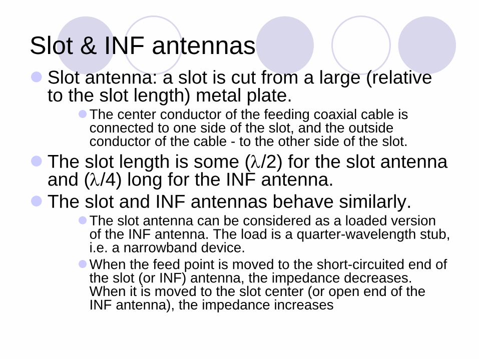
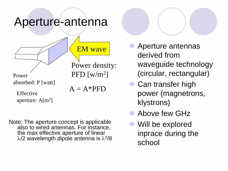

Outline
IntroductionReview of basic antenna types Radiation pattern gain polarizationEquivalent circuit amp radiation efficiencySmart antennasSome theorySummary
Radiation pattern
The radiation pattern of antenna is a representation (pictorial or mathematical) of the distribution of the power out-flowing (radiated) from the antenna (in the case of transmitting antenna) or inflowing (received) to the antenna (in the case of receiving antenna) as a function of direction angles from the antenna
Antenna radiation pattern (antenna pattern) bull is defined for large distances from the antenna where the spatial
(angular) distribution of the radiated power does not depend on the distance from the radiation source
bull is independent on the power flow direction it is the same when the antenna is used to transmit and when it is used to receive radio waves
bull is usually different for different frequencies and different polarizations of radio wave radiated received
Power pattern vs Field pattern
The power pattern is the measured (calculated) and plotted received power |P(θ ϕ)| at a constant (large) distance from the antenna The amplitude field pattern is the measured (calculated) and plotted electric (magnetic) field intensity |E(θ ϕ)| or |H(θ ϕ)| at a constant (large) distance from the antenna
Power or field-strength meter
Antenna under test
Turntable
Generator
Auxiliary antenna
Large distance
The power pattern and the field patterns are inter-relatedP(θ ϕ) = (1η)|E(θ ϕ)|2 = η|H(θ ϕ)|2
P = powerE = electrical field component vectorH = magnetic field component vectorη
= 377 ohm (free-space plane wave impedance)
Normalized pattern
Usually the pattern describes the normalized field (power) values with respect to the maximum value
Note The power pattern and the amplitude field pattern are the same when computed and when plotted in dB
3-D pattern
Antenna radiation pattern is 3-dimensionalThe 3-D plot of antenna pattern assumes both angles θ and ϕ varying which is difficult to produce and to interpret
3-D pattern
Source NK Nikolova
2-D pattern
Two 2-D patterns
Usually the antenna pattern is presented as a 2-D plot with only one of the direction angles θ or ϕ variesIt is an intersection of the 3-D one with a given plane
usually it is a θ = const plane or a ϕ= const plane that contains the patternrsquos maximum
Source NK Nikolova
Example a short dipole on z-axis
Source NK Nikolova
Principal patterns
Principal patterns are the 2-D patterns of linearly polarized antennas measured in 2 planes
1 the E-plane a plane parallel to the E vector and containing the direction of maximum radiation and
2 the H-plane a plane parallel to the H vector orthogonal to the E-plane and containing the direction of maximum radiation Source NK Nikolova
Example
Source NK Nikolova
Antenna Mask (Example 1)
Typical relative directivity- mask of receiving antenna (Yagi ant TV dcm waves)
[CCIR doc 11645 17-Oct 1989)-20
-15
-10
-5
0
-180
-120 -6
0 0 60 120
180
Azimith angle degrees
Rel
ativ
e ga
in d
B
Antenna Mask (Example 2)
-50
-40
-30
-20
-10
0
01 1 10 100
PhiPhi0
Rela
tive
gain
(dB)
RR1998 APS30 Fig9
COPOLAR
CROSSPOLAR
Reference pattern for co-polar and cross-polar components for satellite transmitting antennas in Regions 1 and 3 (Broadcasting ~12 GHz)
0dB
-3dBPhi
Isotropic antenna
Isotropic antenna or isotropic radiator is a hypothetical (not physically realizable) concept used as a useful reference to describe real antennas Isotropic antenna radiates equally in all directions
Its radiation pattern is represented by a sphere whose center coincides with the location of the isotropic radiator
Source NK Nikolova
Directional antenna
Directional antenna is an antenna which radiates (or receives) much more power in (or from) some directions than in (or from) others
Note Usually this term is applied to antennas whose directivity is much higher than that of a half-wavelength dipole
Source NK Nikolova
Omnidirectional antenna
An antenna which has a non-directional pattern in a plane
It is usually directional in other planes
Source NK Nikolova
Pattern lobes
Source NK Nikolova
Pattern lobe is a portion of the radiation pattern with a local maximum
Lobes are classified as major minor side lobes back lobes
Pattern lobes and beam widths
Source NK Nikolova
Beamwidth
Half-power beamwidth (HPBW) is the angle between two vectors from the patternrsquos origin to the points of the major lobe where the radiation intensity is half its maximum
Often used to describe the antenna resolution propertiesImportant in radar technology radioastronomy etc
First-null beamwidth (FNBW) is the angle between two vectors originating at the patternrsquos origin and tangent to the main beam at its base
Often FNBW asymp 2HPBW
Example
Source NK Nikolova
Anisotropic sources gainEvery real antenna radiates more energy in some directions than in others (ie has directional properties)Idealized example of directional antenna the radiated energy is concentrated in the yellow region (cone) Directive antenna gain the power flux density is increased by (roughly) the inverse ratio of the yellow area and the total surface of the isotropic sphere
Gain in the field intensity may also be considered - it is equal to the square root of the power gain
Isotropic sphere
Antenna gain measurement
Antenna Gain = (PPo ) S=S0
Actual antenna
P = Power delivered to the actual antenna
S = Power received
(the same in both steps)
Measuring equipment
Step 2 substitution
Reference antenna
Po = Power delivered to the reference
antenna
S0 = Power received
(the same in both steps)
Measuring equipment
Step 1 reference
Antenna Gains Gi Gd
Unless otherwise specified the gain refers to the direction of maximum radiation Gain is a dimension-less factor related to power and usually expressed in decibelsGi ldquoIsotropic Power Gainrdquo ndash theoretical concept the reference antenna is isotropicGd - the reference antenna is a half-wave dipole
Typical Gain and Beamwidth
Type of antenna Gi [dB] BeamW
Isotropic 0 3600x3600
Half-wave Dipole 2 3600x1200
Helix (10 turn) 14 350x350
Small dish 16 300x300
Large dish 45 10x10
Antenna gain and effective area
Measure of the effective absorption area presented by an antenna to an incident plane wave Depends on the antenna gain and wavelength2
2( ) [m ]4eA Gλη θ ϕπ
=
Aperture efficiency ηa = Ae AA physical area of antennarsquos aperture square meters
Power Transfer in Free Space
λ wavelength [m]PR power available at the receiving antenna PT power delivered to the transmitting antennaGR gain of the transmitting antenna in the direction of the receiving antenna GT gain of the receiving antenna in the direction of the transmitting antenna Matched polarizations
2
2
2
4
44
⎟⎠⎞
⎜⎝⎛=
⎟⎟⎠
⎞⎜⎜⎝
⎛⎟⎠⎞
⎜⎝⎛=
sdot=
rGGP
GrPG
APFDP
RTT
RTT
eR
πλ
πλ
π
eirp
Equivalent Isotropically Radiated Power (in a given direction)
The product of the power supplied to the antenna and the antenna gain (relative to an isotropic antenna) in a given direction
ie i r p PG=
Linear Polarization
In a linearly polarized plane wave the direction of the E (or H) vector is constant
httpwwwamanogawacomarchivewavesAhtml
Elliptical Polarization
Ex = cos (wt)Ey = cos (wt)
Ex = cos (wt)Ey = cos (wt+pi4)
Ex = cos (wt)Ey = -sin (wt)
Ex = cos (wt)Ey = cos (wt+3pi4)
Ex = cos (wt)Ey = -cos (wt+pi4)
Ex = cos (wt)Ey = sin (wt)
LHC
RHC
Polarization ellipse
The superposition of two plane-wave components results in an elliptically polarized waveThe polarization ellipse is defined by its axial ratio NM (ellipticity) tilt angle ψand sense of rotation
Ey
Ex
M
N
ψ
Polarization states
450 LINEAR
UPPER HEMISPHEREELLIPTIC POLARIZATIONLEFT_HANDED SENSE
LOWER HEMISPHEREELLIPTIC POLARIZATION RIGHT_HANDED SENSE
EQUATORLINEAR POLARIZATION
LATTITUDEREPRESENTSAXIAL RATIO
LONGITUDEREPRESENTSTILT ANGLE
POLES REPRESENTCIRCULAR POLARIZATIONS
LHC
RHC
(Poincareacute sphere)
Comments on Polarization
At any moment in a chosen reference point in space there is actually a single electric vector E (and associated magnetic vector H)This is the result of superposition (addition) of the instantaneous fields E (and H) produced by all radiation sources active at the moment The separation of fields by their wavelength polarization or direction is the result of lsquofiltrationrsquo
Antenna Polarization
The polarization of an antenna in a specific direction is defined to be the polarization of the wave produced by the antenna at a great distance at this direction
Polarization Efficiency
The power received by an antenna from a particular direction is maximal if the polarization of the incident wave and the polarization of the antenna in the wave arrival direction have
the same axial ratiothe same sense of polarizationthe same spatial orientation
Polarization filters reflectors
At the surface of ideal conductor the tangential electrical field component = 0
|E1 |gt0 |E2 | = 0
Vector E perp
wiresVector E ||
wires
|E1 |gt0 |E2 | ~ |E2|
Wall of thin parallel wires (conductors)
Wire distance ~ 01λ
Outline
IntroductionReview of basic antenna types Radiation pattern gain polarizationEquivalent circuit amp radiation efficiencySmart antennasSome theorySummary
Transmitting antenna equivalent circuit
Transmitter Transm line
AntennaG
ener
ator
RG
jXG
VG
jXA
Rr
Rl
The transmitter with the transmission line is represented by an (Thevenin) equivalent generator
The antenna is represented by its input impedance (which is frequency-dependent and is influenced by objects nearby) as seem from the generator
jXA represents energy stored in electric (Ee ) and magnetic (Em ) near-field components if |Ee| = |Em | then XA = 0 (antenna resonance)
Rr represents energy radiated into space (far-field components)
Rl represents energy lost ie transformed into heat in the antenna structure
Radio wave
Receiving antenna equivalent circuitA
nten
naRr
jXA
VA
jXL
RLRl
Thevenin equivalent
The antenna with the transmission line is represented by an (Thevenin) equivalent generator
The receiver is represented by its input impedance as seen from the antenna terminals (ie transformed by the transmission line)
VA is the (induced by the incident wave) voltage at the antenna terminals determined when the antenna is open circuited
Note The antenna impedance is the same when the antenna is used to radiate and when it is used to receive energy
Radio wave ReceiverTransmline
Antenna
Power transfer
The maximum power is delivered to (or from) the antenna when the antenna impedance and the impedance of the equivalent generator (or load) are matched
0
05
1
01 1 10
RA RG (XA+XG = 0)
PA
PAm
ax
When the impedances are matchedHalf of the source power is delivered to the load and half is dissipated within the (equivalent) generator as heatIn the case of receiving antenna a part (Pl) of the power captured is lost as heat in the antenna elements the other part being reradiated (scattered) back into space
Even when the antenna losses tend to zero still only half of the power captured is delivered to the load (in the case of conjugate matching) the other half being scattered back into space
When the antenna impedance is not matched to the transmitter output impedance (or to the receiver input impedance) or to the transmission line between them impedance-matching devices must be used for maximum power transferInexpensive impedance-matching devices are usually narrow-band Transmission lines often have significant losses
Radiation efficiency
The radiation efficiency e indicates how efficiently the antenna uses the RF power It is the ratio of the power radiated by the antenna and the total power delivered to the antenna terminals (in transmitting mode) In terms of equivalent circuit parameters
r
r l
ReR R
=+
Outline
IntroductionReview of basic antenna types Radiation pattern gain polarizationEquivalent circuit amp radiation efficiencySmart antennasSome theorySummary
Antenna arrays
Consist of multiple (usually identical) antennas (elements) lsquocollaboratingrsquo to synthesize radiation characteristics not available with a single antenna They are able
to match the radiation pattern to the desired coverage area to change the radiation pattern electronically (electronic scanning) through the control of the phase and the amplitude of the signal fed to each elementto adapt to changing signal conditionsto increase transmission capacity by better use of the radio resources and reducing interference
Complex amp costlybull Intensive research related to military space etc activities
Smart antennas signal-processing antennas tracking antennas phased arrays etc
Source adapted from N Gregorieva
Satellite antennas (TV)
Not an array
Owens Valley Radio Observatory
The Earthrsquos atmosphere is transparent in the narrow visible-light window (4000-7000 angstroms) and the radio band between 1 mm and 10 m
[Sky amp Telescope Feb 1997 p26]
The New Mexico Very Large Array
27 antennas along 3 railroad tracks provide baselines up to 35 km Radio images are formed by correlating the signals garnered by each antenna
[Sky amp TelescopeFeb 1997 p 30]
2 GHz adaptive antenna
A set of 48 2GHz antennas
Source Arraycomm
Phased Arrays
Array of N antennas in a linear or two-dimensional configuration + beam-forming amp control deviceThe amplitude and phase excitation of each individual antenna controlled electronically (ldquosoftware-definedrdquo)
Diode phase shifters Ferrite phase shifters
Inertia-less beam-forming and scanning (μsec) with fixed physical structure
Switched beam antennasBased on switching function between separate directive antennas or predefined beams of an array
Space Division Multiple Access(SDMA) = allocating an angle direction sector to each user
In a TDMA system two users will be allocated to the same time slot and the same carrier frequency They will be differentiated by different direction angles
Dynamically phased array (PA)
A generalization of the switched lobe conceptThe radiation pattern continuously track the designated signal (user) Include a direction of arrival(DoA) tracking algorithm
Beam Steering
Beam-steering using phase shifters at each radiating element
Radiatingelements
Powerdistribution
Phaseshifters
Equi-phasewave front
Δ
= [(2πλ)d sinθ]
3Δ 2Δ Δ 0
θ
d
Beam direction
4-Bit Phase-Shifter (Example)
Alternative solution Transmission line with controlled delay
00 or 2250 00 or 450 00 or 900 00 or 1800Input Output
Bit 4 Bit 3 Bit 2 Bit 1
Steering Beam-forming Circuitry
Switched-Line Phase Bit
Phase bit = delay difference
Input Output
Diode switch
Delay line 1a
Delay line 1b
Simulation
2 omnidirectional antennas (equal amplitudes)Variables
distance incrementphase increment
N omnidirectional antennas Group factor (N omnidirectional antennas uniformly distributed along a straight line equal amplitudes equal phase increment)
httpwwwamanogawacomarchiveTwoDipoleAntenna2-2html (more details)
2 omnidirectional antennas
-1
-05
0
05
1
-1 -05 0 05 1
D = 05λ θ= 900
-1
-05
0
05
1
-1 -05 0 05 1
-1
-05
0
05
1
-1 -05 0 05 1
D = 05λ θ= 00 D = 05λ θ= 1800
N omnidirectional antennas
Array gain (line uniform identical power)
0
05
1
15
2
25
-180 -90 0 90 180
Azimuth angle degrees
Rel
ativ
e ga
in
N = 2 θ
= 900 N = 9 θ
= 450N = 5 θ
= 1800
0
1
2
3
4
5
6
-180 -90 0 90 180
Azimuth angle degrees
Rel
ativ
e ga
in
0
1
2
3
4
5
6
7
8
9
10
-180 -90 0 90 180
Azimuth angle degrees
Rel
ativ
e ga
in
Antenna Arrays Benefits
Possibilities to control electronically Direction of maximum radiationDirections (positions) of nullsBeam-widthDirectivityLevels of sidelobes
using standard antennas (or antenna collections) independently of their radiation patternsAntenna elements can be distributed along straight lines arcs squares circles etc
Adaptive (ldquoIntelligentrdquo)AntennasArray of N antennas in a linear circular or planar configurationUsed for selection signals from desired sources and suppress incident signals from undesired sourcesThe antenna pattern track the sources It is then adjusted to null out the interferers and to maximize the signal to interference ratio (SIR)Able to receive and combine constructively multipath signals
The amplitude phase excitation of each antenna controlled electronically (ldquosoftware-definedrdquo) The weight-determining algorithm uses a-priori and or measured information to adapt antenna to changing environmentThe weight and summing circuits can operate at the RF and or at an intermediate frequency
w1
wN
Σ
Weight-determining algorithm
1
N
Antenna sitting
Radio horizonEffects of obstacles amp structures nearbySafety
operating procedures Grounding
lightning strikesstatic charges
Surge protectionlightning searches for a second path to ground
Outline
IntroductionReview of basic antenna types Radiation pattern gain polarizationEquivalent circuit amp radiation efficiencySmart antennasSome theorySummary
Maxwellrsquos Equations
EM field interacting with the matter2 coupled vectors E and H (6 numbers) varying with time and
space and satisfying the boundary conditions (see httpwwwamanogawacomarchivedocsEM1pdf httpwwwamanogawacomarchivedocsEM7pdf httpwwwamanogawacomarchivedocsEM5pdf)
Reciprocity TheoremAntenna characteristics do not depend on the direction of energyflow The impedance amp radiation pattern are the same when the antenna radiates signal and when it receives it Note This theorem is valid only for linear passive antennas (ie antennas that do not contain nonlinear and unilateral elements eg amplifiers)
EM Field of Current Element
ϕϑ
ϕϑ
HHHH
EEEE
r
r
++=
++=
I current (monochromatic) [A] dz antenna element (short) [m]x
y
z
θ
ϕ
OP
r
ErEθ
Eϕ
I dz 222
222
ϕϑ
ϕϑ
HHHH
EEEE
r
r
++=
++=
Short dipole antenna summary
Eθ amp Hθ are maximal in the equatorial plane zero along the antenna axisEr is maximal along the antenna axis dz zero in the equatorial plane All show axial symmetry All are proportional to the current moment IdzHave 3 components that decrease with the distance-to-wavelength ratio as
(rλ)-2 amp (rλ)-3 near-field or induction field The energy oscillates from entirely electric to entirely magnetic and back twice per cycle Modeled as a resonant LC circuit or resonator (rλ)-1 far-field or radiation field These 3 component are all equal at (rλ) = 1(2π)
Field components
0001
001
01
1
10
100
1000
01 1 10
Relative distance Br
Rel
ativ
e fie
ldst
reng
th
FF
FF
Q
Q
C
C
FF Radiation field
C Q Induction fields
β
Field impedance
Field impedanc eZ = EH depends on the antenna type and on distance
001
01
1
10
100
001 01 1 10 100
Distance (lambda 2Pi)
Z 3
77
Short dipole
Small loop
Far-Field Near-Field
Near-field region Angular distribution of energy depends on distance from the antenna Reactive field components dominate (L C)
Far-field region Angular distribution of energy is independent on distance Radiating field component dominates (R)The resultant EM field can locally be treated as uniform (TEM)
Poynting vector
The time-rate of EM energy flow per unit area in free space is the Poynting vector(see httpwwwamanogawacomarchivedocsEM8pdf) It is the cross-product (vector product right-hand screw direction) of the electric field vector (E) and the magnetic field vector (H) P = E x H For the elementary dipole Eθ perp Hθ and only EθxHθ carry energy into space with the speed of light
Power Flow
In free space and at large distances the radiated energy streams from the antenna in radial lines ie the Poynting vector has only the radial component in spherical coordinates A source that radiates uniformly in all directions is an isotropic source (radiator antenna) For such a source the radial component of the Poynting vector is independent of θ and ϕ
Linear Antennas
Summation of all vector components E (or H) produced by each antenna element
In the far-field region the vector componentsare parallel to each otherPhase difference due to
Excitation phase differencePath distance difference
Method of moments
321
321
+++=
+++=
HHHH
EEEE
O
Simulation Linear dipole antenna
httpwwwamanogawacomarchiveDipoleAntDipoleAnt-2html
Linear dipole antennahttpwwwamanogawacomarchiveAntenna1Antenna1-2html
Detailed analysis
Point Source
For many purposes it is sufficient to know the direction (angle) variation of the power radiated by antenna at large distances For that purpose any practical antenna regardless of its size and complexity can be represented as a point-source The actual field near the antenna is then disregarded
The EM field at large distances from an antenna can be treated as originated at a point source - fictitious volume-less emitterThe EM field in a homogenous unlimited medium at large distances from an antenna can be approximated by an uniform plane TEM wave
Image Theory
Antenna above perfectly conducting plane surfaceTangential electrical field component = 0
vertical components the same directionhorizontal components opposite directions
The field (above the ground) is the same as if the ground is replaced by an mirror image of the antenna httpwwwamanogawacomarchivewavesAhtml
+
-
Elliptical polarization change of the rotation sense
Antenna Bandwidth
Zeland Software Inc amp BAY TECHNOLOGY
IE3D Benchmark Simulation Example
Smith Chart
Zeland Software Inc amp BAY TECHNOLOGY
IE3D Benchmark Simulation Example
Electromagnetic Radiation
Power Flux Density
Far Field Expression
hIR
ejkEjkR
πη
4~
minus
minus
R
Vg
ηERH timesˆ
~
Antenna Pattern 3D
Antenna Pattern 2D
Zeland Software Inc amp BAY TECHNOLOGY
IE3D Benchmark Simulation Example
Directivity Gain
Power flux density
Directivity Gain
RR
hIREHEP ˆ
8ˆ
21
21
2
22
2
2
λη
==times=
ttD P
hI
RP
EG
22
2
2
2
24
21
η
λπ
π
η ==
Polarization
Axial Ratio
Zeland Software Inc amp BAY TECHNOLOGY
IE3D Benchmark Simulation Example
Antenna Simulation
Zeland Software Inc amp BAY TECHNOLOGY IE3D Benchmark Simulation Example
Software IE3D
Zeland Software httpwwwzelandcom
Receiving Antenna
Z L
Receiver
AntennaΣ
Equivalent Circuit of Receiving Antenna
V oc
Z A
Σ
Z LZo
hEV ioc bullminus=
Optimal Receiving Condition
V oc
Z A
Σ
Z LZo
hEV ioc plusmn=
ZrsquoL
A
L ZZ =A
ocr R
VP
8
2
=
Effective Area of a Receiving Antenna
DAA
e
e
i
A
i
A
i
r
GRh
Rh
A
AE
RhE
RhE
P
πλ
λ
πη
πλη
η
η
η
444
2428
2
2
22
2
22222
=⎟⎟⎟
⎠
⎞
⎜⎜⎜
⎝
⎛==
=⎟⎟⎟
⎠
⎞
⎜⎜⎜
⎝
⎛==
Friis Formula
R
Tx Ant Rx Ant
DRDTt
eRDTt
r GGR
PAGR
PPπλ
ππ 444
2
22 ==
DRDTt
r GGRP
P 2
4⎟⎠⎞
⎜⎝⎛=πλ
Diversity
Transmitter Receiver
Linear Dipole Dipole
Input Impedance
白光弘 天線原理及應用 明文書局 1992
Radiation Patterns
Image Theory for Electric Currents
Slot Antennas
Image Theory for Magnetic Currents
Microstrip Antennas
Microstrip Traveling-Wave Antennas
白光弘 天線原理及應用 明文書局 1992
Microstrip Slot Antennas
Radiation Mechanism
Input Resistance vs Feeding Point
白光弘 天線原理及應用 明文書局 1992
Radiation Pattern
白光弘 天線原理及應用 明文書局 1992
Microstrip Antenna Array Element
白光弘 天線原理及應用 明文書局 1992
Broadband Antennas
Log Periodic Antennas
Antenna Array
Antenna Array Patterns
- Radiation of electromagnetic waves
- Outline
- Antenna purpose
- Antenna functions
- Monopole (dipole over plane)
- Outline
- Antennas for laptop applications
- Slide Number 8
- Slot amp INF antennas
- Exampledouble-layer printed Yagi antenna
- Slide Number 11
- Aperture-antenna
- Leaky-wave antennas
- Reflector antennas
- Planar reflectors
- Paraboloidal reflectors
- The largest radio telescopes
- The Arecibo Observatory Antenna System
- The Arecibo Radio Telescope
- Lens antennas
- Outline
- Radiation pattern
- Power pattern vs Field pattern
- Normalized pattern
- 3-D pattern
- 2-D pattern
- Example a short dipole on z-axis
- Principal patterns
- Example
- Antenna Mask (Example 1)
- Antenna Mask (Example 2)
- Isotropic antenna
- Directional antenna
- Omnidirectional antenna
- Pattern lobes
- Pattern lobes and beam widths
- Beamwidth
- Example
- Anisotropic sources gain
- Antenna gain measurement
- Antenna Gains Gi Gd
- Typical Gain and Beamwidth
- Antenna gain and effective area
- Power Transfer in Free Space
- eirp
- Linear Polarization
- Elliptical Polarization
- Polarization ellipse
- Polarization states
- Comments on Polarization
- Antenna Polarization
- Polarization Efficiency
- Polarization filters reflectors
- Outline
- Transmitting antenna equivalent circuit
- Receiving antenna equivalent circuit
- Power transfer
- Slide Number 63
- Slide Number 64
- Radiation efficiency
- Outline
- Antenna arrays
- Satellite antennas (TV)
- Owens Valley Radio Observatory
- The New Mexico Very Large Array
- 2 GHz adaptive antenna
- Phased Arrays
- Slide Number 73
- Slide Number 74
- Beam Steering
- 4-Bit Phase-Shifter (Example)
- Switched-Line Phase Bit
- Simulation
- 2 omnidirectional antennas
- N omnidirectional antennas
- Antenna Arrays Benefits
- Adaptive (ldquoIntelligentrdquo)Antennas
- Slide Number 83
- Antenna sitting
- Outline
- Maxwellrsquos Equations
- EM Field of Current Element
- Short dipole antenna summary
- Field components
- Field impedance
- Far-Field Near-Field
- Poynting vector
- Power Flow
- Linear Antennas
- Simulation Linear dipole antenna
- Point Source
- Slide Number 97
- Image Theory
- Antenna Bandwidth
- Smith Chart
- Electromagnetic Radiation
- Power Flux Density
- Far Field Expression
- Antenna Pattern 3D
- Antenna Pattern 2D
- Directivity Gain
- Polarization
- Axial Ratio
- Antenna Simulation
- Software IE3D
- Zeland Software httpwwwzelandcom
- Receiving Antenna
- Equivalent Circuit of Receiving Antenna
- Optimal Receiving Condition
- Effective Area of a Receiving Antenna
- Friis Formula
- Diversity
- Linear Dipole Dipole
- Input Impedance
- Radiation Patterns
- Image Theory for Electric Currents
- Slot Antennas
- Image Theory for Magnetic Currents
- Microstrip Antennas
- Microstrip Traveling-Wave Antennas
- Microstrip Slot Antennas
- Radiation Mechanism
- Input Resistance vs Feeding Point
- Radiation Pattern
- Microstrip Antenna Array Element
- Broadband Antennas
- Log Periodic Antennas
- Antenna Array
- Antenna Array Patterns
-
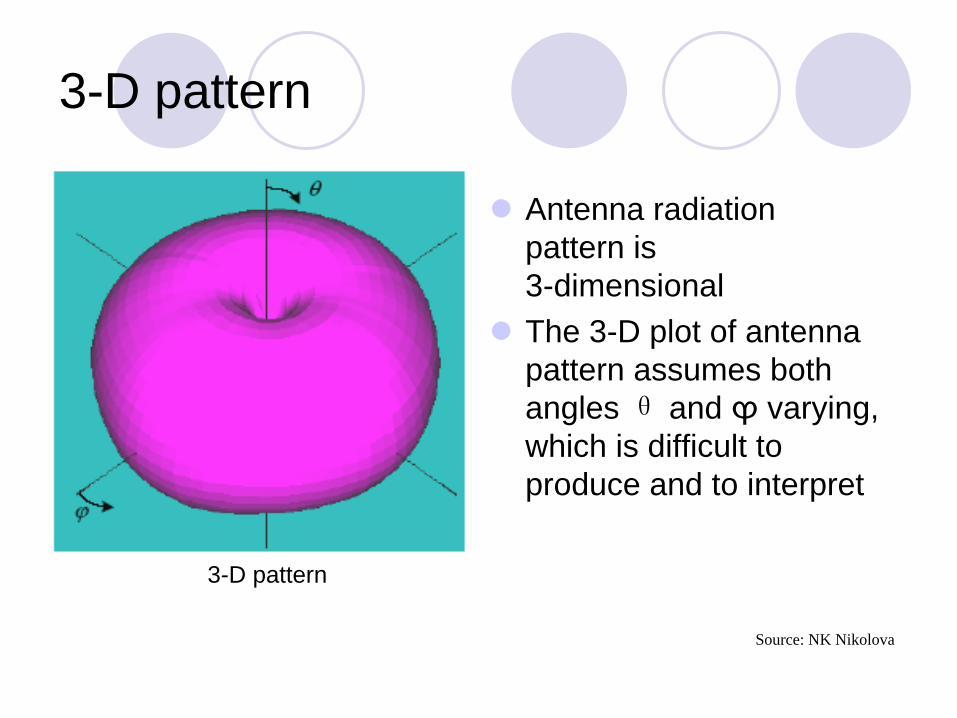
3-D pattern
Antenna radiation pattern is 3-dimensionalThe 3-D plot of antenna pattern assumes both angles θ and ϕ varying which is difficult to produce and to interpret
3-D pattern
Source NK Nikolova
2-D pattern
Two 2-D patterns
Usually the antenna pattern is presented as a 2-D plot with only one of the direction angles θ or ϕ variesIt is an intersection of the 3-D one with a given plane
usually it is a θ = const plane or a ϕ= const plane that contains the patternrsquos maximum
Source NK Nikolova
Example a short dipole on z-axis
Source NK Nikolova
Principal patterns
Principal patterns are the 2-D patterns of linearly polarized antennas measured in 2 planes
1 the E-plane a plane parallel to the E vector and containing the direction of maximum radiation and
2 the H-plane a plane parallel to the H vector orthogonal to the E-plane and containing the direction of maximum radiation Source NK Nikolova
Example
Source NK Nikolova
Antenna Mask (Example 1)
Typical relative directivity- mask of receiving antenna (Yagi ant TV dcm waves)
[CCIR doc 11645 17-Oct 1989)-20
-15
-10
-5
0
-180
-120 -6
0 0 60 120
180
Azimith angle degrees
Rel
ativ
e ga
in d
B
Antenna Mask (Example 2)
-50
-40
-30
-20
-10
0
01 1 10 100
PhiPhi0
Rela
tive
gain
(dB)
RR1998 APS30 Fig9
COPOLAR
CROSSPOLAR
Reference pattern for co-polar and cross-polar components for satellite transmitting antennas in Regions 1 and 3 (Broadcasting ~12 GHz)
0dB
-3dBPhi
Isotropic antenna
Isotropic antenna or isotropic radiator is a hypothetical (not physically realizable) concept used as a useful reference to describe real antennas Isotropic antenna radiates equally in all directions
Its radiation pattern is represented by a sphere whose center coincides with the location of the isotropic radiator
Source NK Nikolova
Directional antenna
Directional antenna is an antenna which radiates (or receives) much more power in (or from) some directions than in (or from) others
Note Usually this term is applied to antennas whose directivity is much higher than that of a half-wavelength dipole
Source NK Nikolova
Omnidirectional antenna
An antenna which has a non-directional pattern in a plane
It is usually directional in other planes
Source NK Nikolova
Pattern lobes
Source NK Nikolova
Pattern lobe is a portion of the radiation pattern with a local maximum
Lobes are classified as major minor side lobes back lobes
Pattern lobes and beam widths
Source NK Nikolova
Beamwidth
Half-power beamwidth (HPBW) is the angle between two vectors from the patternrsquos origin to the points of the major lobe where the radiation intensity is half its maximum
Often used to describe the antenna resolution propertiesImportant in radar technology radioastronomy etc
First-null beamwidth (FNBW) is the angle between two vectors originating at the patternrsquos origin and tangent to the main beam at its base
Often FNBW asymp 2HPBW
Example
Source NK Nikolova
Anisotropic sources gainEvery real antenna radiates more energy in some directions than in others (ie has directional properties)Idealized example of directional antenna the radiated energy is concentrated in the yellow region (cone) Directive antenna gain the power flux density is increased by (roughly) the inverse ratio of the yellow area and the total surface of the isotropic sphere
Gain in the field intensity may also be considered - it is equal to the square root of the power gain
Isotropic sphere
Antenna gain measurement
Antenna Gain = (PPo ) S=S0
Actual antenna
P = Power delivered to the actual antenna
S = Power received
(the same in both steps)
Measuring equipment
Step 2 substitution
Reference antenna
Po = Power delivered to the reference
antenna
S0 = Power received
(the same in both steps)
Measuring equipment
Step 1 reference
Antenna Gains Gi Gd
Unless otherwise specified the gain refers to the direction of maximum radiation Gain is a dimension-less factor related to power and usually expressed in decibelsGi ldquoIsotropic Power Gainrdquo ndash theoretical concept the reference antenna is isotropicGd - the reference antenna is a half-wave dipole
Typical Gain and Beamwidth
Type of antenna Gi [dB] BeamW
Isotropic 0 3600x3600
Half-wave Dipole 2 3600x1200
Helix (10 turn) 14 350x350
Small dish 16 300x300
Large dish 45 10x10
Antenna gain and effective area
Measure of the effective absorption area presented by an antenna to an incident plane wave Depends on the antenna gain and wavelength2
2( ) [m ]4eA Gλη θ ϕπ
=
Aperture efficiency ηa = Ae AA physical area of antennarsquos aperture square meters
Power Transfer in Free Space
λ wavelength [m]PR power available at the receiving antenna PT power delivered to the transmitting antennaGR gain of the transmitting antenna in the direction of the receiving antenna GT gain of the receiving antenna in the direction of the transmitting antenna Matched polarizations
2
2
2
4
44
⎟⎠⎞
⎜⎝⎛=
⎟⎟⎠
⎞⎜⎜⎝
⎛⎟⎠⎞
⎜⎝⎛=
sdot=
rGGP
GrPG
APFDP
RTT
RTT
eR
πλ
πλ
π
eirp
Equivalent Isotropically Radiated Power (in a given direction)
The product of the power supplied to the antenna and the antenna gain (relative to an isotropic antenna) in a given direction
ie i r p PG=
Linear Polarization
In a linearly polarized plane wave the direction of the E (or H) vector is constant
httpwwwamanogawacomarchivewavesAhtml
Elliptical Polarization
Ex = cos (wt)Ey = cos (wt)
Ex = cos (wt)Ey = cos (wt+pi4)
Ex = cos (wt)Ey = -sin (wt)
Ex = cos (wt)Ey = cos (wt+3pi4)
Ex = cos (wt)Ey = -cos (wt+pi4)
Ex = cos (wt)Ey = sin (wt)
LHC
RHC
Polarization ellipse
The superposition of two plane-wave components results in an elliptically polarized waveThe polarization ellipse is defined by its axial ratio NM (ellipticity) tilt angle ψand sense of rotation
Ey
Ex
M
N
ψ
Polarization states
450 LINEAR
UPPER HEMISPHEREELLIPTIC POLARIZATIONLEFT_HANDED SENSE
LOWER HEMISPHEREELLIPTIC POLARIZATION RIGHT_HANDED SENSE
EQUATORLINEAR POLARIZATION
LATTITUDEREPRESENTSAXIAL RATIO
LONGITUDEREPRESENTSTILT ANGLE
POLES REPRESENTCIRCULAR POLARIZATIONS
LHC
RHC
(Poincareacute sphere)
Comments on Polarization
At any moment in a chosen reference point in space there is actually a single electric vector E (and associated magnetic vector H)This is the result of superposition (addition) of the instantaneous fields E (and H) produced by all radiation sources active at the moment The separation of fields by their wavelength polarization or direction is the result of lsquofiltrationrsquo
Antenna Polarization
The polarization of an antenna in a specific direction is defined to be the polarization of the wave produced by the antenna at a great distance at this direction
Polarization Efficiency
The power received by an antenna from a particular direction is maximal if the polarization of the incident wave and the polarization of the antenna in the wave arrival direction have
the same axial ratiothe same sense of polarizationthe same spatial orientation
Polarization filters reflectors
At the surface of ideal conductor the tangential electrical field component = 0
|E1 |gt0 |E2 | = 0
Vector E perp
wiresVector E ||
wires
|E1 |gt0 |E2 | ~ |E2|
Wall of thin parallel wires (conductors)
Wire distance ~ 01λ
Outline
IntroductionReview of basic antenna types Radiation pattern gain polarizationEquivalent circuit amp radiation efficiencySmart antennasSome theorySummary
Transmitting antenna equivalent circuit
Transmitter Transm line
AntennaG
ener
ator
RG
jXG
VG
jXA
Rr
Rl
The transmitter with the transmission line is represented by an (Thevenin) equivalent generator
The antenna is represented by its input impedance (which is frequency-dependent and is influenced by objects nearby) as seem from the generator
jXA represents energy stored in electric (Ee ) and magnetic (Em ) near-field components if |Ee| = |Em | then XA = 0 (antenna resonance)
Rr represents energy radiated into space (far-field components)
Rl represents energy lost ie transformed into heat in the antenna structure
Radio wave
Receiving antenna equivalent circuitA
nten
naRr
jXA
VA
jXL
RLRl
Thevenin equivalent
The antenna with the transmission line is represented by an (Thevenin) equivalent generator
The receiver is represented by its input impedance as seen from the antenna terminals (ie transformed by the transmission line)
VA is the (induced by the incident wave) voltage at the antenna terminals determined when the antenna is open circuited
Note The antenna impedance is the same when the antenna is used to radiate and when it is used to receive energy
Radio wave ReceiverTransmline
Antenna
Power transfer
The maximum power is delivered to (or from) the antenna when the antenna impedance and the impedance of the equivalent generator (or load) are matched
0
05
1
01 1 10
RA RG (XA+XG = 0)
PA
PAm
ax
When the impedances are matchedHalf of the source power is delivered to the load and half is dissipated within the (equivalent) generator as heatIn the case of receiving antenna a part (Pl) of the power captured is lost as heat in the antenna elements the other part being reradiated (scattered) back into space
Even when the antenna losses tend to zero still only half of the power captured is delivered to the load (in the case of conjugate matching) the other half being scattered back into space
When the antenna impedance is not matched to the transmitter output impedance (or to the receiver input impedance) or to the transmission line between them impedance-matching devices must be used for maximum power transferInexpensive impedance-matching devices are usually narrow-band Transmission lines often have significant losses
Radiation efficiency
The radiation efficiency e indicates how efficiently the antenna uses the RF power It is the ratio of the power radiated by the antenna and the total power delivered to the antenna terminals (in transmitting mode) In terms of equivalent circuit parameters
r
r l
ReR R
=+
Outline
IntroductionReview of basic antenna types Radiation pattern gain polarizationEquivalent circuit amp radiation efficiencySmart antennasSome theorySummary
Antenna arrays
Consist of multiple (usually identical) antennas (elements) lsquocollaboratingrsquo to synthesize radiation characteristics not available with a single antenna They are able
to match the radiation pattern to the desired coverage area to change the radiation pattern electronically (electronic scanning) through the control of the phase and the amplitude of the signal fed to each elementto adapt to changing signal conditionsto increase transmission capacity by better use of the radio resources and reducing interference
Complex amp costlybull Intensive research related to military space etc activities
Smart antennas signal-processing antennas tracking antennas phased arrays etc
Source adapted from N Gregorieva
Satellite antennas (TV)
Not an array
Owens Valley Radio Observatory
The Earthrsquos atmosphere is transparent in the narrow visible-light window (4000-7000 angstroms) and the radio band between 1 mm and 10 m
[Sky amp Telescope Feb 1997 p26]
The New Mexico Very Large Array
27 antennas along 3 railroad tracks provide baselines up to 35 km Radio images are formed by correlating the signals garnered by each antenna
[Sky amp TelescopeFeb 1997 p 30]
2 GHz adaptive antenna
A set of 48 2GHz antennas
Source Arraycomm
Phased Arrays
Array of N antennas in a linear or two-dimensional configuration + beam-forming amp control deviceThe amplitude and phase excitation of each individual antenna controlled electronically (ldquosoftware-definedrdquo)
Diode phase shifters Ferrite phase shifters
Inertia-less beam-forming and scanning (μsec) with fixed physical structure
Switched beam antennasBased on switching function between separate directive antennas or predefined beams of an array
Space Division Multiple Access(SDMA) = allocating an angle direction sector to each user
In a TDMA system two users will be allocated to the same time slot and the same carrier frequency They will be differentiated by different direction angles
Dynamically phased array (PA)
A generalization of the switched lobe conceptThe radiation pattern continuously track the designated signal (user) Include a direction of arrival(DoA) tracking algorithm
Beam Steering
Beam-steering using phase shifters at each radiating element
Radiatingelements
Powerdistribution
Phaseshifters
Equi-phasewave front
Δ
= [(2πλ)d sinθ]
3Δ 2Δ Δ 0
θ
d
Beam direction
4-Bit Phase-Shifter (Example)
Alternative solution Transmission line with controlled delay
00 or 2250 00 or 450 00 or 900 00 or 1800Input Output
Bit 4 Bit 3 Bit 2 Bit 1
Steering Beam-forming Circuitry
Switched-Line Phase Bit
Phase bit = delay difference
Input Output
Diode switch
Delay line 1a
Delay line 1b
Simulation
2 omnidirectional antennas (equal amplitudes)Variables
distance incrementphase increment
N omnidirectional antennas Group factor (N omnidirectional antennas uniformly distributed along a straight line equal amplitudes equal phase increment)
httpwwwamanogawacomarchiveTwoDipoleAntenna2-2html (more details)
2 omnidirectional antennas
-1
-05
0
05
1
-1 -05 0 05 1
D = 05λ θ= 900
-1
-05
0
05
1
-1 -05 0 05 1
-1
-05
0
05
1
-1 -05 0 05 1
D = 05λ θ= 00 D = 05λ θ= 1800
N omnidirectional antennas
Array gain (line uniform identical power)
0
05
1
15
2
25
-180 -90 0 90 180
Azimuth angle degrees
Rel
ativ
e ga
in
N = 2 θ
= 900 N = 9 θ
= 450N = 5 θ
= 1800
0
1
2
3
4
5
6
-180 -90 0 90 180
Azimuth angle degrees
Rel
ativ
e ga
in
0
1
2
3
4
5
6
7
8
9
10
-180 -90 0 90 180
Azimuth angle degrees
Rel
ativ
e ga
in
Antenna Arrays Benefits
Possibilities to control electronically Direction of maximum radiationDirections (positions) of nullsBeam-widthDirectivityLevels of sidelobes
using standard antennas (or antenna collections) independently of their radiation patternsAntenna elements can be distributed along straight lines arcs squares circles etc
Adaptive (ldquoIntelligentrdquo)AntennasArray of N antennas in a linear circular or planar configurationUsed for selection signals from desired sources and suppress incident signals from undesired sourcesThe antenna pattern track the sources It is then adjusted to null out the interferers and to maximize the signal to interference ratio (SIR)Able to receive and combine constructively multipath signals
The amplitude phase excitation of each antenna controlled electronically (ldquosoftware-definedrdquo) The weight-determining algorithm uses a-priori and or measured information to adapt antenna to changing environmentThe weight and summing circuits can operate at the RF and or at an intermediate frequency
w1
wN
Σ
Weight-determining algorithm
1
N
Antenna sitting
Radio horizonEffects of obstacles amp structures nearbySafety
operating procedures Grounding
lightning strikesstatic charges
Surge protectionlightning searches for a second path to ground
Outline
IntroductionReview of basic antenna types Radiation pattern gain polarizationEquivalent circuit amp radiation efficiencySmart antennasSome theorySummary
Maxwellrsquos Equations
EM field interacting with the matter2 coupled vectors E and H (6 numbers) varying with time and
space and satisfying the boundary conditions (see httpwwwamanogawacomarchivedocsEM1pdf httpwwwamanogawacomarchivedocsEM7pdf httpwwwamanogawacomarchivedocsEM5pdf)
Reciprocity TheoremAntenna characteristics do not depend on the direction of energyflow The impedance amp radiation pattern are the same when the antenna radiates signal and when it receives it Note This theorem is valid only for linear passive antennas (ie antennas that do not contain nonlinear and unilateral elements eg amplifiers)
EM Field of Current Element
ϕϑ
ϕϑ
HHHH
EEEE
r
r
++=
++=
I current (monochromatic) [A] dz antenna element (short) [m]x
y
z
θ
ϕ
OP
r
ErEθ
Eϕ
I dz 222
222
ϕϑ
ϕϑ
HHHH
EEEE
r
r
++=
++=
Short dipole antenna summary
Eθ amp Hθ are maximal in the equatorial plane zero along the antenna axisEr is maximal along the antenna axis dz zero in the equatorial plane All show axial symmetry All are proportional to the current moment IdzHave 3 components that decrease with the distance-to-wavelength ratio as
(rλ)-2 amp (rλ)-3 near-field or induction field The energy oscillates from entirely electric to entirely magnetic and back twice per cycle Modeled as a resonant LC circuit or resonator (rλ)-1 far-field or radiation field These 3 component are all equal at (rλ) = 1(2π)
Field components
0001
001
01
1
10
100
1000
01 1 10
Relative distance Br
Rel
ativ
e fie
ldst
reng
th
FF
FF
Q
Q
C
C
FF Radiation field
C Q Induction fields
β
Field impedance
Field impedanc eZ = EH depends on the antenna type and on distance
001
01
1
10
100
001 01 1 10 100
Distance (lambda 2Pi)
Z 3
77
Short dipole
Small loop
Far-Field Near-Field
Near-field region Angular distribution of energy depends on distance from the antenna Reactive field components dominate (L C)
Far-field region Angular distribution of energy is independent on distance Radiating field component dominates (R)The resultant EM field can locally be treated as uniform (TEM)
Poynting vector
The time-rate of EM energy flow per unit area in free space is the Poynting vector(see httpwwwamanogawacomarchivedocsEM8pdf) It is the cross-product (vector product right-hand screw direction) of the electric field vector (E) and the magnetic field vector (H) P = E x H For the elementary dipole Eθ perp Hθ and only EθxHθ carry energy into space with the speed of light
Power Flow
In free space and at large distances the radiated energy streams from the antenna in radial lines ie the Poynting vector has only the radial component in spherical coordinates A source that radiates uniformly in all directions is an isotropic source (radiator antenna) For such a source the radial component of the Poynting vector is independent of θ and ϕ
Linear Antennas
Summation of all vector components E (or H) produced by each antenna element
In the far-field region the vector componentsare parallel to each otherPhase difference due to
Excitation phase differencePath distance difference
Method of moments
321
321
+++=
+++=
HHHH
EEEE
O
Simulation Linear dipole antenna
httpwwwamanogawacomarchiveDipoleAntDipoleAnt-2html
Linear dipole antennahttpwwwamanogawacomarchiveAntenna1Antenna1-2html
Detailed analysis
Point Source
For many purposes it is sufficient to know the direction (angle) variation of the power radiated by antenna at large distances For that purpose any practical antenna regardless of its size and complexity can be represented as a point-source The actual field near the antenna is then disregarded
The EM field at large distances from an antenna can be treated as originated at a point source - fictitious volume-less emitterThe EM field in a homogenous unlimited medium at large distances from an antenna can be approximated by an uniform plane TEM wave
Image Theory
Antenna above perfectly conducting plane surfaceTangential electrical field component = 0
vertical components the same directionhorizontal components opposite directions
The field (above the ground) is the same as if the ground is replaced by an mirror image of the antenna httpwwwamanogawacomarchivewavesAhtml
+
-
Elliptical polarization change of the rotation sense
Antenna Bandwidth
Zeland Software Inc amp BAY TECHNOLOGY
IE3D Benchmark Simulation Example
Smith Chart
Zeland Software Inc amp BAY TECHNOLOGY
IE3D Benchmark Simulation Example
Electromagnetic Radiation
Power Flux Density
Far Field Expression
hIR
ejkEjkR
πη
4~
minus
minus
R
Vg
ηERH timesˆ
~
Antenna Pattern 3D
Antenna Pattern 2D
Zeland Software Inc amp BAY TECHNOLOGY
IE3D Benchmark Simulation Example
Directivity Gain
Power flux density
Directivity Gain
RR
hIREHEP ˆ
8ˆ
21
21
2
22
2
2
λη
==times=
ttD P
hI
RP
EG
22
2
2
2
24
21
η
λπ
π
η ==
Polarization
Axial Ratio
Zeland Software Inc amp BAY TECHNOLOGY
IE3D Benchmark Simulation Example
Antenna Simulation
Zeland Software Inc amp BAY TECHNOLOGY IE3D Benchmark Simulation Example
Software IE3D
Zeland Software httpwwwzelandcom
Receiving Antenna
Z L
Receiver
AntennaΣ
Equivalent Circuit of Receiving Antenna
V oc
Z A
Σ
Z LZo
hEV ioc bullminus=
Optimal Receiving Condition
V oc
Z A
Σ
Z LZo
hEV ioc plusmn=
ZrsquoL
A
L ZZ =A
ocr R
VP
8
2
=
Effective Area of a Receiving Antenna
DAA
e
e
i
A
i
A
i
r
GRh
Rh
A
AE
RhE
RhE
P
πλ
λ
πη
πλη
η
η
η
444
2428
2
2
22
2
22222
=⎟⎟⎟
⎠
⎞
⎜⎜⎜
⎝
⎛==
=⎟⎟⎟
⎠
⎞
⎜⎜⎜
⎝
⎛==
Friis Formula
R
Tx Ant Rx Ant
DRDTt
eRDTt
r GGR
PAGR
PPπλ
ππ 444
2
22 ==
DRDTt
r GGRP
P 2
4⎟⎠⎞
⎜⎝⎛=πλ
Diversity
Transmitter Receiver
Linear Dipole Dipole
Input Impedance
白光弘 天線原理及應用 明文書局 1992
Radiation Patterns
Image Theory for Electric Currents
Slot Antennas
Image Theory for Magnetic Currents
Microstrip Antennas
Microstrip Traveling-Wave Antennas
白光弘 天線原理及應用 明文書局 1992
Microstrip Slot Antennas
Radiation Mechanism
Input Resistance vs Feeding Point
白光弘 天線原理及應用 明文書局 1992
Radiation Pattern
白光弘 天線原理及應用 明文書局 1992
Microstrip Antenna Array Element
白光弘 天線原理及應用 明文書局 1992
Broadband Antennas
Log Periodic Antennas
Antenna Array
Antenna Array Patterns
- Radiation of electromagnetic waves
- Outline
- Antenna purpose
- Antenna functions
- Monopole (dipole over plane)
- Outline
- Antennas for laptop applications
- Slide Number 8
- Slot amp INF antennas
- Exampledouble-layer printed Yagi antenna
- Slide Number 11
- Aperture-antenna
- Leaky-wave antennas
- Reflector antennas
- Planar reflectors
- Paraboloidal reflectors
- The largest radio telescopes
- The Arecibo Observatory Antenna System
- The Arecibo Radio Telescope
- Lens antennas
- Outline
- Radiation pattern
- Power pattern vs Field pattern
- Normalized pattern
- 3-D pattern
- 2-D pattern
- Example a short dipole on z-axis
- Principal patterns
- Example
- Antenna Mask (Example 1)
- Antenna Mask (Example 2)
- Isotropic antenna
- Directional antenna
- Omnidirectional antenna
- Pattern lobes
- Pattern lobes and beam widths
- Beamwidth
- Example
- Anisotropic sources gain
- Antenna gain measurement
- Antenna Gains Gi Gd
- Typical Gain and Beamwidth
- Antenna gain and effective area
- Power Transfer in Free Space
- eirp
- Linear Polarization
- Elliptical Polarization
- Polarization ellipse
- Polarization states
- Comments on Polarization
- Antenna Polarization
- Polarization Efficiency
- Polarization filters reflectors
- Outline
- Transmitting antenna equivalent circuit
- Receiving antenna equivalent circuit
- Power transfer
- Slide Number 63
- Slide Number 64
- Radiation efficiency
- Outline
- Antenna arrays
- Satellite antennas (TV)
- Owens Valley Radio Observatory
- The New Mexico Very Large Array
- 2 GHz adaptive antenna
- Phased Arrays
- Slide Number 73
- Slide Number 74
- Beam Steering
- 4-Bit Phase-Shifter (Example)
- Switched-Line Phase Bit
- Simulation
- 2 omnidirectional antennas
- N omnidirectional antennas
- Antenna Arrays Benefits
- Adaptive (ldquoIntelligentrdquo)Antennas
- Slide Number 83
- Antenna sitting
- Outline
- Maxwellrsquos Equations
- EM Field of Current Element
- Short dipole antenna summary
- Field components
- Field impedance
- Far-Field Near-Field
- Poynting vector
- Power Flow
- Linear Antennas
- Simulation Linear dipole antenna
- Point Source
- Slide Number 97
- Image Theory
- Antenna Bandwidth
- Smith Chart
- Electromagnetic Radiation
- Power Flux Density
- Far Field Expression
- Antenna Pattern 3D
- Antenna Pattern 2D
- Directivity Gain
- Polarization
- Axial Ratio
- Antenna Simulation
- Software IE3D
- Zeland Software httpwwwzelandcom
- Receiving Antenna
- Equivalent Circuit of Receiving Antenna
- Optimal Receiving Condition
- Effective Area of a Receiving Antenna
- Friis Formula
- Diversity
- Linear Dipole Dipole
- Input Impedance
- Radiation Patterns
- Image Theory for Electric Currents
- Slot Antennas
- Image Theory for Magnetic Currents
- Microstrip Antennas
- Microstrip Traveling-Wave Antennas
- Microstrip Slot Antennas
- Radiation Mechanism
- Input Resistance vs Feeding Point
- Radiation Pattern
- Microstrip Antenna Array Element
- Broadband Antennas
- Log Periodic Antennas
- Antenna Array
- Antenna Array Patterns
-

Example
Source NK Nikolova
Antenna Mask (Example 1)
Typical relative directivity- mask of receiving antenna (Yagi ant TV dcm waves)
[CCIR doc 11645 17-Oct 1989)-20
-15
-10
-5
0
-180
-120 -6
0 0 60 120
180
Azimith angle degrees
Rel
ativ
e ga
in d
B
Antenna Mask (Example 2)
-50
-40
-30
-20
-10
0
01 1 10 100
PhiPhi0
Rela
tive
gain
(dB)
RR1998 APS30 Fig9
COPOLAR
CROSSPOLAR
Reference pattern for co-polar and cross-polar components for satellite transmitting antennas in Regions 1 and 3 (Broadcasting ~12 GHz)
0dB
-3dBPhi
Isotropic antenna
Isotropic antenna or isotropic radiator is a hypothetical (not physically realizable) concept used as a useful reference to describe real antennas Isotropic antenna radiates equally in all directions
Its radiation pattern is represented by a sphere whose center coincides with the location of the isotropic radiator
Source NK Nikolova
Directional antenna
Directional antenna is an antenna which radiates (or receives) much more power in (or from) some directions than in (or from) others
Note Usually this term is applied to antennas whose directivity is much higher than that of a half-wavelength dipole
Source NK Nikolova
Omnidirectional antenna
An antenna which has a non-directional pattern in a plane
It is usually directional in other planes
Source NK Nikolova
Pattern lobes
Source NK Nikolova
Pattern lobe is a portion of the radiation pattern with a local maximum
Lobes are classified as major minor side lobes back lobes
Pattern lobes and beam widths
Source NK Nikolova
Beamwidth
Half-power beamwidth (HPBW) is the angle between two vectors from the patternrsquos origin to the points of the major lobe where the radiation intensity is half its maximum
Often used to describe the antenna resolution propertiesImportant in radar technology radioastronomy etc
First-null beamwidth (FNBW) is the angle between two vectors originating at the patternrsquos origin and tangent to the main beam at its base
Often FNBW asymp 2HPBW
Example
Source NK Nikolova
Anisotropic sources gainEvery real antenna radiates more energy in some directions than in others (ie has directional properties)Idealized example of directional antenna the radiated energy is concentrated in the yellow region (cone) Directive antenna gain the power flux density is increased by (roughly) the inverse ratio of the yellow area and the total surface of the isotropic sphere
Gain in the field intensity may also be considered - it is equal to the square root of the power gain
Isotropic sphere
Antenna gain measurement
Antenna Gain = (PPo ) S=S0
Actual antenna
P = Power delivered to the actual antenna
S = Power received
(the same in both steps)
Measuring equipment
Step 2 substitution
Reference antenna
Po = Power delivered to the reference
antenna
S0 = Power received
(the same in both steps)
Measuring equipment
Step 1 reference
Antenna Gains Gi Gd
Unless otherwise specified the gain refers to the direction of maximum radiation Gain is a dimension-less factor related to power and usually expressed in decibelsGi ldquoIsotropic Power Gainrdquo ndash theoretical concept the reference antenna is isotropicGd - the reference antenna is a half-wave dipole
Typical Gain and Beamwidth
Type of antenna Gi [dB] BeamW
Isotropic 0 3600x3600
Half-wave Dipole 2 3600x1200
Helix (10 turn) 14 350x350
Small dish 16 300x300
Large dish 45 10x10
Antenna gain and effective area
Measure of the effective absorption area presented by an antenna to an incident plane wave Depends on the antenna gain and wavelength2
2( ) [m ]4eA Gλη θ ϕπ
=
Aperture efficiency ηa = Ae AA physical area of antennarsquos aperture square meters
Power Transfer in Free Space
λ wavelength [m]PR power available at the receiving antenna PT power delivered to the transmitting antennaGR gain of the transmitting antenna in the direction of the receiving antenna GT gain of the receiving antenna in the direction of the transmitting antenna Matched polarizations
2
2
2
4
44
⎟⎠⎞
⎜⎝⎛=
⎟⎟⎠
⎞⎜⎜⎝
⎛⎟⎠⎞
⎜⎝⎛=
sdot=
rGGP
GrPG
APFDP
RTT
RTT
eR
πλ
πλ
π
eirp
Equivalent Isotropically Radiated Power (in a given direction)
The product of the power supplied to the antenna and the antenna gain (relative to an isotropic antenna) in a given direction
ie i r p PG=
Linear Polarization
In a linearly polarized plane wave the direction of the E (or H) vector is constant
httpwwwamanogawacomarchivewavesAhtml
Elliptical Polarization
Ex = cos (wt)Ey = cos (wt)
Ex = cos (wt)Ey = cos (wt+pi4)
Ex = cos (wt)Ey = -sin (wt)
Ex = cos (wt)Ey = cos (wt+3pi4)
Ex = cos (wt)Ey = -cos (wt+pi4)
Ex = cos (wt)Ey = sin (wt)
LHC
RHC
Polarization ellipse
The superposition of two plane-wave components results in an elliptically polarized waveThe polarization ellipse is defined by its axial ratio NM (ellipticity) tilt angle ψand sense of rotation
Ey
Ex
M
N
ψ
Polarization states
450 LINEAR
UPPER HEMISPHEREELLIPTIC POLARIZATIONLEFT_HANDED SENSE
LOWER HEMISPHEREELLIPTIC POLARIZATION RIGHT_HANDED SENSE
EQUATORLINEAR POLARIZATION
LATTITUDEREPRESENTSAXIAL RATIO
LONGITUDEREPRESENTSTILT ANGLE
POLES REPRESENTCIRCULAR POLARIZATIONS
LHC
RHC
(Poincareacute sphere)
Comments on Polarization
At any moment in a chosen reference point in space there is actually a single electric vector E (and associated magnetic vector H)This is the result of superposition (addition) of the instantaneous fields E (and H) produced by all radiation sources active at the moment The separation of fields by their wavelength polarization or direction is the result of lsquofiltrationrsquo
Antenna Polarization
The polarization of an antenna in a specific direction is defined to be the polarization of the wave produced by the antenna at a great distance at this direction
Polarization Efficiency
The power received by an antenna from a particular direction is maximal if the polarization of the incident wave and the polarization of the antenna in the wave arrival direction have
the same axial ratiothe same sense of polarizationthe same spatial orientation
Polarization filters reflectors
At the surface of ideal conductor the tangential electrical field component = 0
|E1 |gt0 |E2 | = 0
Vector E perp
wiresVector E ||
wires
|E1 |gt0 |E2 | ~ |E2|
Wall of thin parallel wires (conductors)
Wire distance ~ 01λ
Outline
IntroductionReview of basic antenna types Radiation pattern gain polarizationEquivalent circuit amp radiation efficiencySmart antennasSome theorySummary
Transmitting antenna equivalent circuit
Transmitter Transm line
AntennaG
ener
ator
RG
jXG
VG
jXA
Rr
Rl
The transmitter with the transmission line is represented by an (Thevenin) equivalent generator
The antenna is represented by its input impedance (which is frequency-dependent and is influenced by objects nearby) as seem from the generator
jXA represents energy stored in electric (Ee ) and magnetic (Em ) near-field components if |Ee| = |Em | then XA = 0 (antenna resonance)
Rr represents energy radiated into space (far-field components)
Rl represents energy lost ie transformed into heat in the antenna structure
Radio wave
Receiving antenna equivalent circuitA
nten
naRr
jXA
VA
jXL
RLRl
Thevenin equivalent
The antenna with the transmission line is represented by an (Thevenin) equivalent generator
The receiver is represented by its input impedance as seen from the antenna terminals (ie transformed by the transmission line)
VA is the (induced by the incident wave) voltage at the antenna terminals determined when the antenna is open circuited
Note The antenna impedance is the same when the antenna is used to radiate and when it is used to receive energy
Radio wave ReceiverTransmline
Antenna
Power transfer
The maximum power is delivered to (or from) the antenna when the antenna impedance and the impedance of the equivalent generator (or load) are matched
0
05
1
01 1 10
RA RG (XA+XG = 0)
PA
PAm
ax
When the impedances are matchedHalf of the source power is delivered to the load and half is dissipated within the (equivalent) generator as heatIn the case of receiving antenna a part (Pl) of the power captured is lost as heat in the antenna elements the other part being reradiated (scattered) back into space
Even when the antenna losses tend to zero still only half of the power captured is delivered to the load (in the case of conjugate matching) the other half being scattered back into space
When the antenna impedance is not matched to the transmitter output impedance (or to the receiver input impedance) or to the transmission line between them impedance-matching devices must be used for maximum power transferInexpensive impedance-matching devices are usually narrow-band Transmission lines often have significant losses
Radiation efficiency
The radiation efficiency e indicates how efficiently the antenna uses the RF power It is the ratio of the power radiated by the antenna and the total power delivered to the antenna terminals (in transmitting mode) In terms of equivalent circuit parameters
r
r l
ReR R
=+
Outline
IntroductionReview of basic antenna types Radiation pattern gain polarizationEquivalent circuit amp radiation efficiencySmart antennasSome theorySummary
Antenna arrays
Consist of multiple (usually identical) antennas (elements) lsquocollaboratingrsquo to synthesize radiation characteristics not available with a single antenna They are able
to match the radiation pattern to the desired coverage area to change the radiation pattern electronically (electronic scanning) through the control of the phase and the amplitude of the signal fed to each elementto adapt to changing signal conditionsto increase transmission capacity by better use of the radio resources and reducing interference
Complex amp costlybull Intensive research related to military space etc activities
Smart antennas signal-processing antennas tracking antennas phased arrays etc
Source adapted from N Gregorieva
Satellite antennas (TV)
Not an array
Owens Valley Radio Observatory
The Earthrsquos atmosphere is transparent in the narrow visible-light window (4000-7000 angstroms) and the radio band between 1 mm and 10 m
[Sky amp Telescope Feb 1997 p26]
The New Mexico Very Large Array
27 antennas along 3 railroad tracks provide baselines up to 35 km Radio images are formed by correlating the signals garnered by each antenna
[Sky amp TelescopeFeb 1997 p 30]
2 GHz adaptive antenna
A set of 48 2GHz antennas
Source Arraycomm
Phased Arrays
Array of N antennas in a linear or two-dimensional configuration + beam-forming amp control deviceThe amplitude and phase excitation of each individual antenna controlled electronically (ldquosoftware-definedrdquo)
Diode phase shifters Ferrite phase shifters
Inertia-less beam-forming and scanning (μsec) with fixed physical structure
Switched beam antennasBased on switching function between separate directive antennas or predefined beams of an array
Space Division Multiple Access(SDMA) = allocating an angle direction sector to each user
In a TDMA system two users will be allocated to the same time slot and the same carrier frequency They will be differentiated by different direction angles
Dynamically phased array (PA)
A generalization of the switched lobe conceptThe radiation pattern continuously track the designated signal (user) Include a direction of arrival(DoA) tracking algorithm
Beam Steering
Beam-steering using phase shifters at each radiating element
Radiatingelements
Powerdistribution
Phaseshifters
Equi-phasewave front
Δ
= [(2πλ)d sinθ]
3Δ 2Δ Δ 0
θ
d
Beam direction
4-Bit Phase-Shifter (Example)
Alternative solution Transmission line with controlled delay
00 or 2250 00 or 450 00 or 900 00 or 1800Input Output
Bit 4 Bit 3 Bit 2 Bit 1
Steering Beam-forming Circuitry
Switched-Line Phase Bit
Phase bit = delay difference
Input Output
Diode switch
Delay line 1a
Delay line 1b
Simulation
2 omnidirectional antennas (equal amplitudes)Variables
distance incrementphase increment
N omnidirectional antennas Group factor (N omnidirectional antennas uniformly distributed along a straight line equal amplitudes equal phase increment)
httpwwwamanogawacomarchiveTwoDipoleAntenna2-2html (more details)
2 omnidirectional antennas
-1
-05
0
05
1
-1 -05 0 05 1
D = 05λ θ= 900
-1
-05
0
05
1
-1 -05 0 05 1
-1
-05
0
05
1
-1 -05 0 05 1
D = 05λ θ= 00 D = 05λ θ= 1800
N omnidirectional antennas
Array gain (line uniform identical power)
0
05
1
15
2
25
-180 -90 0 90 180
Azimuth angle degrees
Rel
ativ
e ga
in
N = 2 θ
= 900 N = 9 θ
= 450N = 5 θ
= 1800
0
1
2
3
4
5
6
-180 -90 0 90 180
Azimuth angle degrees
Rel
ativ
e ga
in
0
1
2
3
4
5
6
7
8
9
10
-180 -90 0 90 180
Azimuth angle degrees
Rel
ativ
e ga
in
Antenna Arrays Benefits
Possibilities to control electronically Direction of maximum radiationDirections (positions) of nullsBeam-widthDirectivityLevels of sidelobes
using standard antennas (or antenna collections) independently of their radiation patternsAntenna elements can be distributed along straight lines arcs squares circles etc
Adaptive (ldquoIntelligentrdquo)AntennasArray of N antennas in a linear circular or planar configurationUsed for selection signals from desired sources and suppress incident signals from undesired sourcesThe antenna pattern track the sources It is then adjusted to null out the interferers and to maximize the signal to interference ratio (SIR)Able to receive and combine constructively multipath signals
The amplitude phase excitation of each antenna controlled electronically (ldquosoftware-definedrdquo) The weight-determining algorithm uses a-priori and or measured information to adapt antenna to changing environmentThe weight and summing circuits can operate at the RF and or at an intermediate frequency
w1
wN
Σ
Weight-determining algorithm
1
N
Antenna sitting
Radio horizonEffects of obstacles amp structures nearbySafety
operating procedures Grounding
lightning strikesstatic charges
Surge protectionlightning searches for a second path to ground
Outline
IntroductionReview of basic antenna types Radiation pattern gain polarizationEquivalent circuit amp radiation efficiencySmart antennasSome theorySummary
Maxwellrsquos Equations
EM field interacting with the matter2 coupled vectors E and H (6 numbers) varying with time and
space and satisfying the boundary conditions (see httpwwwamanogawacomarchivedocsEM1pdf httpwwwamanogawacomarchivedocsEM7pdf httpwwwamanogawacomarchivedocsEM5pdf)
Reciprocity TheoremAntenna characteristics do not depend on the direction of energyflow The impedance amp radiation pattern are the same when the antenna radiates signal and when it receives it Note This theorem is valid only for linear passive antennas (ie antennas that do not contain nonlinear and unilateral elements eg amplifiers)
EM Field of Current Element
ϕϑ
ϕϑ
HHHH
EEEE
r
r
++=
++=
I current (monochromatic) [A] dz antenna element (short) [m]x
y
z
θ
ϕ
OP
r
ErEθ
Eϕ
I dz 222
222
ϕϑ
ϕϑ
HHHH
EEEE
r
r
++=
++=
Short dipole antenna summary
Eθ amp Hθ are maximal in the equatorial plane zero along the antenna axisEr is maximal along the antenna axis dz zero in the equatorial plane All show axial symmetry All are proportional to the current moment IdzHave 3 components that decrease with the distance-to-wavelength ratio as
(rλ)-2 amp (rλ)-3 near-field or induction field The energy oscillates from entirely electric to entirely magnetic and back twice per cycle Modeled as a resonant LC circuit or resonator (rλ)-1 far-field or radiation field These 3 component are all equal at (rλ) = 1(2π)
Field components
0001
001
01
1
10
100
1000
01 1 10
Relative distance Br
Rel
ativ
e fie
ldst
reng
th
FF
FF
Q
Q
C
C
FF Radiation field
C Q Induction fields
β
Field impedance
Field impedanc eZ = EH depends on the antenna type and on distance
001
01
1
10
100
001 01 1 10 100
Distance (lambda 2Pi)
Z 3
77
Short dipole
Small loop
Far-Field Near-Field
Near-field region Angular distribution of energy depends on distance from the antenna Reactive field components dominate (L C)
Far-field region Angular distribution of energy is independent on distance Radiating field component dominates (R)The resultant EM field can locally be treated as uniform (TEM)
Poynting vector
The time-rate of EM energy flow per unit area in free space is the Poynting vector(see httpwwwamanogawacomarchivedocsEM8pdf) It is the cross-product (vector product right-hand screw direction) of the electric field vector (E) and the magnetic field vector (H) P = E x H For the elementary dipole Eθ perp Hθ and only EθxHθ carry energy into space with the speed of light
Power Flow
In free space and at large distances the radiated energy streams from the antenna in radial lines ie the Poynting vector has only the radial component in spherical coordinates A source that radiates uniformly in all directions is an isotropic source (radiator antenna) For such a source the radial component of the Poynting vector is independent of θ and ϕ
Linear Antennas
Summation of all vector components E (or H) produced by each antenna element
In the far-field region the vector componentsare parallel to each otherPhase difference due to
Excitation phase differencePath distance difference
Method of moments
321
321
+++=
+++=
HHHH
EEEE
O
Simulation Linear dipole antenna
httpwwwamanogawacomarchiveDipoleAntDipoleAnt-2html
Linear dipole antennahttpwwwamanogawacomarchiveAntenna1Antenna1-2html
Detailed analysis
Point Source
For many purposes it is sufficient to know the direction (angle) variation of the power radiated by antenna at large distances For that purpose any practical antenna regardless of its size and complexity can be represented as a point-source The actual field near the antenna is then disregarded
The EM field at large distances from an antenna can be treated as originated at a point source - fictitious volume-less emitterThe EM field in a homogenous unlimited medium at large distances from an antenna can be approximated by an uniform plane TEM wave
Image Theory
Antenna above perfectly conducting plane surfaceTangential electrical field component = 0
vertical components the same directionhorizontal components opposite directions
The field (above the ground) is the same as if the ground is replaced by an mirror image of the antenna httpwwwamanogawacomarchivewavesAhtml
+
-
Elliptical polarization change of the rotation sense
Antenna Bandwidth
Zeland Software Inc amp BAY TECHNOLOGY
IE3D Benchmark Simulation Example
Smith Chart
Zeland Software Inc amp BAY TECHNOLOGY
IE3D Benchmark Simulation Example
Electromagnetic Radiation
Power Flux Density
Far Field Expression
hIR
ejkEjkR
πη
4~
minus
minus
R
Vg
ηERH timesˆ
~
Antenna Pattern 3D
Antenna Pattern 2D
Zeland Software Inc amp BAY TECHNOLOGY
IE3D Benchmark Simulation Example
Directivity Gain
Power flux density
Directivity Gain
RR
hIREHEP ˆ
8ˆ
21
21
2
22
2
2
λη
==times=
ttD P
hI
RP
EG
22
2
2
2
24
21
η
λπ
π
η ==
Polarization
Axial Ratio
Zeland Software Inc amp BAY TECHNOLOGY
IE3D Benchmark Simulation Example
Antenna Simulation
Zeland Software Inc amp BAY TECHNOLOGY IE3D Benchmark Simulation Example
Software IE3D
Zeland Software httpwwwzelandcom
Receiving Antenna
Z L
Receiver
AntennaΣ
Equivalent Circuit of Receiving Antenna
V oc
Z A
Σ
Z LZo
hEV ioc bullminus=
Optimal Receiving Condition
V oc
Z A
Σ
Z LZo
hEV ioc plusmn=
ZrsquoL
A
L ZZ =A
ocr R
VP
8
2
=
Effective Area of a Receiving Antenna
DAA
e
e
i
A
i
A
i
r
GRh
Rh
A
AE
RhE
RhE
P
πλ
λ
πη
πλη
η
η
η
444
2428
2
2
22
2
22222
=⎟⎟⎟
⎠
⎞
⎜⎜⎜
⎝
⎛==
=⎟⎟⎟
⎠
⎞
⎜⎜⎜
⎝
⎛==
Friis Formula
R
Tx Ant Rx Ant
DRDTt
eRDTt
r GGR
PAGR
PPπλ
ππ 444
2
22 ==
DRDTt
r GGRP
P 2
4⎟⎠⎞
⎜⎝⎛=πλ
Diversity
Transmitter Receiver
Linear Dipole Dipole
Input Impedance
白光弘 天線原理及應用 明文書局 1992
Radiation Patterns
Image Theory for Electric Currents
Slot Antennas
Image Theory for Magnetic Currents
Microstrip Antennas
Microstrip Traveling-Wave Antennas
白光弘 天線原理及應用 明文書局 1992
Microstrip Slot Antennas
Radiation Mechanism
Input Resistance vs Feeding Point
白光弘 天線原理及應用 明文書局 1992
Radiation Pattern
白光弘 天線原理及應用 明文書局 1992
Microstrip Antenna Array Element
白光弘 天線原理及應用 明文書局 1992
Broadband Antennas
Log Periodic Antennas
Antenna Array
Antenna Array Patterns
- Radiation of electromagnetic waves
- Outline
- Antenna purpose
- Antenna functions
- Monopole (dipole over plane)
- Outline
- Antennas for laptop applications
- Slide Number 8
- Slot amp INF antennas
- Exampledouble-layer printed Yagi antenna
- Slide Number 11
- Aperture-antenna
- Leaky-wave antennas
- Reflector antennas
- Planar reflectors
- Paraboloidal reflectors
- The largest radio telescopes
- The Arecibo Observatory Antenna System
- The Arecibo Radio Telescope
- Lens antennas
- Outline
- Radiation pattern
- Power pattern vs Field pattern
- Normalized pattern
- 3-D pattern
- 2-D pattern
- Example a short dipole on z-axis
- Principal patterns
- Example
- Antenna Mask (Example 1)
- Antenna Mask (Example 2)
- Isotropic antenna
- Directional antenna
- Omnidirectional antenna
- Pattern lobes
- Pattern lobes and beam widths
- Beamwidth
- Example
- Anisotropic sources gain
- Antenna gain measurement
- Antenna Gains Gi Gd
- Typical Gain and Beamwidth
- Antenna gain and effective area
- Power Transfer in Free Space
- eirp
- Linear Polarization
- Elliptical Polarization
- Polarization ellipse
- Polarization states
- Comments on Polarization
- Antenna Polarization
- Polarization Efficiency
- Polarization filters reflectors
- Outline
- Transmitting antenna equivalent circuit
- Receiving antenna equivalent circuit
- Power transfer
- Slide Number 63
- Slide Number 64
- Radiation efficiency
- Outline
- Antenna arrays
- Satellite antennas (TV)
- Owens Valley Radio Observatory
- The New Mexico Very Large Array
- 2 GHz adaptive antenna
- Phased Arrays
- Slide Number 73
- Slide Number 74
- Beam Steering
- 4-Bit Phase-Shifter (Example)
- Switched-Line Phase Bit
- Simulation
- 2 omnidirectional antennas
- N omnidirectional antennas
- Antenna Arrays Benefits
- Adaptive (ldquoIntelligentrdquo)Antennas
- Slide Number 83
- Antenna sitting
- Outline
- Maxwellrsquos Equations
- EM Field of Current Element
- Short dipole antenna summary
- Field components
- Field impedance
- Far-Field Near-Field
- Poynting vector
- Power Flow
- Linear Antennas
- Simulation Linear dipole antenna
- Point Source
- Slide Number 97
- Image Theory
- Antenna Bandwidth
- Smith Chart
- Electromagnetic Radiation
- Power Flux Density
- Far Field Expression
- Antenna Pattern 3D
- Antenna Pattern 2D
- Directivity Gain
- Polarization
- Axial Ratio
- Antenna Simulation
- Software IE3D
- Zeland Software httpwwwzelandcom
- Receiving Antenna
- Equivalent Circuit of Receiving Antenna
- Optimal Receiving Condition
- Effective Area of a Receiving Antenna
- Friis Formula
- Diversity
- Linear Dipole Dipole
- Input Impedance
- Radiation Patterns
- Image Theory for Electric Currents
- Slot Antennas
- Image Theory for Magnetic Currents
- Microstrip Antennas
- Microstrip Traveling-Wave Antennas
- Microstrip Slot Antennas
- Radiation Mechanism
- Input Resistance vs Feeding Point
- Radiation Pattern
- Microstrip Antenna Array Element
- Broadband Antennas
- Log Periodic Antennas
- Antenna Array
- Antenna Array Patterns
-
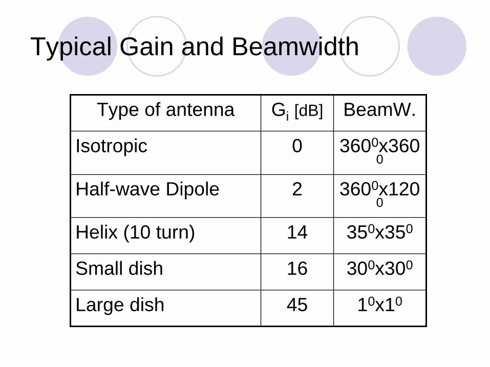

Outline
IntroductionReview of basic antenna types Radiation pattern gain polarizationEquivalent circuit amp radiation efficiencySmart antennasSome theorySummary
Transmitting antenna equivalent circuit
Transmitter Transm line
AntennaG
ener
ator
RG
jXG
VG
jXA
Rr
Rl
The transmitter with the transmission line is represented by an (Thevenin) equivalent generator
The antenna is represented by its input impedance (which is frequency-dependent and is influenced by objects nearby) as seem from the generator
jXA represents energy stored in electric (Ee ) and magnetic (Em ) near-field components if |Ee| = |Em | then XA = 0 (antenna resonance)
Rr represents energy radiated into space (far-field components)
Rl represents energy lost ie transformed into heat in the antenna structure
Radio wave
Receiving antenna equivalent circuitA
nten
naRr
jXA
VA
jXL
RLRl
Thevenin equivalent
The antenna with the transmission line is represented by an (Thevenin) equivalent generator
The receiver is represented by its input impedance as seen from the antenna terminals (ie transformed by the transmission line)
VA is the (induced by the incident wave) voltage at the antenna terminals determined when the antenna is open circuited
Note The antenna impedance is the same when the antenna is used to radiate and when it is used to receive energy
Radio wave ReceiverTransmline
Antenna
Power transfer
The maximum power is delivered to (or from) the antenna when the antenna impedance and the impedance of the equivalent generator (or load) are matched
0
05
1
01 1 10
RA RG (XA+XG = 0)
PA
PAm
ax
When the impedances are matchedHalf of the source power is delivered to the load and half is dissipated within the (equivalent) generator as heatIn the case of receiving antenna a part (Pl) of the power captured is lost as heat in the antenna elements the other part being reradiated (scattered) back into space
Even when the antenna losses tend to zero still only half of the power captured is delivered to the load (in the case of conjugate matching) the other half being scattered back into space
When the antenna impedance is not matched to the transmitter output impedance (or to the receiver input impedance) or to the transmission line between them impedance-matching devices must be used for maximum power transferInexpensive impedance-matching devices are usually narrow-band Transmission lines often have significant losses
Radiation efficiency
The radiation efficiency e indicates how efficiently the antenna uses the RF power It is the ratio of the power radiated by the antenna and the total power delivered to the antenna terminals (in transmitting mode) In terms of equivalent circuit parameters
r
r l
ReR R
=+
Outline
IntroductionReview of basic antenna types Radiation pattern gain polarizationEquivalent circuit amp radiation efficiencySmart antennasSome theorySummary
Antenna arrays
Consist of multiple (usually identical) antennas (elements) lsquocollaboratingrsquo to synthesize radiation characteristics not available with a single antenna They are able
to match the radiation pattern to the desired coverage area to change the radiation pattern electronically (electronic scanning) through the control of the phase and the amplitude of the signal fed to each elementto adapt to changing signal conditionsto increase transmission capacity by better use of the radio resources and reducing interference
Complex amp costlybull Intensive research related to military space etc activities
Smart antennas signal-processing antennas tracking antennas phased arrays etc
Source adapted from N Gregorieva
Satellite antennas (TV)
Not an array
Owens Valley Radio Observatory
The Earthrsquos atmosphere is transparent in the narrow visible-light window (4000-7000 angstroms) and the radio band between 1 mm and 10 m
[Sky amp Telescope Feb 1997 p26]
The New Mexico Very Large Array
27 antennas along 3 railroad tracks provide baselines up to 35 km Radio images are formed by correlating the signals garnered by each antenna
[Sky amp TelescopeFeb 1997 p 30]
2 GHz adaptive antenna
A set of 48 2GHz antennas
Source Arraycomm
Phased Arrays
Array of N antennas in a linear or two-dimensional configuration + beam-forming amp control deviceThe amplitude and phase excitation of each individual antenna controlled electronically (ldquosoftware-definedrdquo)
Diode phase shifters Ferrite phase shifters
Inertia-less beam-forming and scanning (μsec) with fixed physical structure
Switched beam antennasBased on switching function between separate directive antennas or predefined beams of an array
Space Division Multiple Access(SDMA) = allocating an angle direction sector to each user
In a TDMA system two users will be allocated to the same time slot and the same carrier frequency They will be differentiated by different direction angles
Dynamically phased array (PA)
A generalization of the switched lobe conceptThe radiation pattern continuously track the designated signal (user) Include a direction of arrival(DoA) tracking algorithm
Beam Steering
Beam-steering using phase shifters at each radiating element
Radiatingelements
Powerdistribution
Phaseshifters
Equi-phasewave front
Δ
= [(2πλ)d sinθ]
3Δ 2Δ Δ 0
θ
d
Beam direction
4-Bit Phase-Shifter (Example)
Alternative solution Transmission line with controlled delay
00 or 2250 00 or 450 00 or 900 00 or 1800Input Output
Bit 4 Bit 3 Bit 2 Bit 1
Steering Beam-forming Circuitry
Switched-Line Phase Bit
Phase bit = delay difference
Input Output
Diode switch
Delay line 1a
Delay line 1b
Simulation
2 omnidirectional antennas (equal amplitudes)Variables
distance incrementphase increment
N omnidirectional antennas Group factor (N omnidirectional antennas uniformly distributed along a straight line equal amplitudes equal phase increment)
httpwwwamanogawacomarchiveTwoDipoleAntenna2-2html (more details)
2 omnidirectional antennas
-1
-05
0
05
1
-1 -05 0 05 1
D = 05λ θ= 900
-1
-05
0
05
1
-1 -05 0 05 1
-1
-05
0
05
1
-1 -05 0 05 1
D = 05λ θ= 00 D = 05λ θ= 1800
N omnidirectional antennas
Array gain (line uniform identical power)
0
05
1
15
2
25
-180 -90 0 90 180
Azimuth angle degrees
Rel
ativ
e ga
in
N = 2 θ
= 900 N = 9 θ
= 450N = 5 θ
= 1800
0
1
2
3
4
5
6
-180 -90 0 90 180
Azimuth angle degrees
Rel
ativ
e ga
in
0
1
2
3
4
5
6
7
8
9
10
-180 -90 0 90 180
Azimuth angle degrees
Rel
ativ
e ga
in
Antenna Arrays Benefits
Possibilities to control electronically Direction of maximum radiationDirections (positions) of nullsBeam-widthDirectivityLevels of sidelobes
using standard antennas (or antenna collections) independently of their radiation patternsAntenna elements can be distributed along straight lines arcs squares circles etc
Adaptive (ldquoIntelligentrdquo)AntennasArray of N antennas in a linear circular or planar configurationUsed for selection signals from desired sources and suppress incident signals from undesired sourcesThe antenna pattern track the sources It is then adjusted to null out the interferers and to maximize the signal to interference ratio (SIR)Able to receive and combine constructively multipath signals
The amplitude phase excitation of each antenna controlled electronically (ldquosoftware-definedrdquo) The weight-determining algorithm uses a-priori and or measured information to adapt antenna to changing environmentThe weight and summing circuits can operate at the RF and or at an intermediate frequency
w1
wN
Σ
Weight-determining algorithm
1
N
Antenna sitting
Radio horizonEffects of obstacles amp structures nearbySafety
operating procedures Grounding
lightning strikesstatic charges
Surge protectionlightning searches for a second path to ground
Outline
IntroductionReview of basic antenna types Radiation pattern gain polarizationEquivalent circuit amp radiation efficiencySmart antennasSome theorySummary
Maxwellrsquos Equations
EM field interacting with the matter2 coupled vectors E and H (6 numbers) varying with time and
space and satisfying the boundary conditions (see httpwwwamanogawacomarchivedocsEM1pdf httpwwwamanogawacomarchivedocsEM7pdf httpwwwamanogawacomarchivedocsEM5pdf)
Reciprocity TheoremAntenna characteristics do not depend on the direction of energyflow The impedance amp radiation pattern are the same when the antenna radiates signal and when it receives it Note This theorem is valid only for linear passive antennas (ie antennas that do not contain nonlinear and unilateral elements eg amplifiers)
EM Field of Current Element
ϕϑ
ϕϑ
HHHH
EEEE
r
r
++=
++=
I current (monochromatic) [A] dz antenna element (short) [m]x
y
z
θ
ϕ
OP
r
ErEθ
Eϕ
I dz 222
222
ϕϑ
ϕϑ
HHHH
EEEE
r
r
++=
++=
Short dipole antenna summary
Eθ amp Hθ are maximal in the equatorial plane zero along the antenna axisEr is maximal along the antenna axis dz zero in the equatorial plane All show axial symmetry All are proportional to the current moment IdzHave 3 components that decrease with the distance-to-wavelength ratio as
(rλ)-2 amp (rλ)-3 near-field or induction field The energy oscillates from entirely electric to entirely magnetic and back twice per cycle Modeled as a resonant LC circuit or resonator (rλ)-1 far-field or radiation field These 3 component are all equal at (rλ) = 1(2π)
Field components
0001
001
01
1
10
100
1000
01 1 10
Relative distance Br
Rel
ativ
e fie
ldst
reng
th
FF
FF
Q
Q
C
C
FF Radiation field
C Q Induction fields
β
Field impedance
Field impedanc eZ = EH depends on the antenna type and on distance
001
01
1
10
100
001 01 1 10 100
Distance (lambda 2Pi)
Z 3
77
Short dipole
Small loop
Far-Field Near-Field
Near-field region Angular distribution of energy depends on distance from the antenna Reactive field components dominate (L C)
Far-field region Angular distribution of energy is independent on distance Radiating field component dominates (R)The resultant EM field can locally be treated as uniform (TEM)
Poynting vector
The time-rate of EM energy flow per unit area in free space is the Poynting vector(see httpwwwamanogawacomarchivedocsEM8pdf) It is the cross-product (vector product right-hand screw direction) of the electric field vector (E) and the magnetic field vector (H) P = E x H For the elementary dipole Eθ perp Hθ and only EθxHθ carry energy into space with the speed of light
Power Flow
In free space and at large distances the radiated energy streams from the antenna in radial lines ie the Poynting vector has only the radial component in spherical coordinates A source that radiates uniformly in all directions is an isotropic source (radiator antenna) For such a source the radial component of the Poynting vector is independent of θ and ϕ
Linear Antennas
Summation of all vector components E (or H) produced by each antenna element
In the far-field region the vector componentsare parallel to each otherPhase difference due to
Excitation phase differencePath distance difference
Method of moments
321
321
+++=
+++=
HHHH
EEEE
O
Simulation Linear dipole antenna
httpwwwamanogawacomarchiveDipoleAntDipoleAnt-2html
Linear dipole antennahttpwwwamanogawacomarchiveAntenna1Antenna1-2html
Detailed analysis
Point Source
For many purposes it is sufficient to know the direction (angle) variation of the power radiated by antenna at large distances For that purpose any practical antenna regardless of its size and complexity can be represented as a point-source The actual field near the antenna is then disregarded
The EM field at large distances from an antenna can be treated as originated at a point source - fictitious volume-less emitterThe EM field in a homogenous unlimited medium at large distances from an antenna can be approximated by an uniform plane TEM wave
Image Theory
Antenna above perfectly conducting plane surfaceTangential electrical field component = 0
vertical components the same directionhorizontal components opposite directions
The field (above the ground) is the same as if the ground is replaced by an mirror image of the antenna httpwwwamanogawacomarchivewavesAhtml
+
-
Elliptical polarization change of the rotation sense
Antenna Bandwidth
Zeland Software Inc amp BAY TECHNOLOGY
IE3D Benchmark Simulation Example
Smith Chart
Zeland Software Inc amp BAY TECHNOLOGY
IE3D Benchmark Simulation Example
Electromagnetic Radiation
Power Flux Density
Far Field Expression
hIR
ejkEjkR
πη
4~
minus
minus
R
Vg
ηERH timesˆ
~
Antenna Pattern 3D
Antenna Pattern 2D
Zeland Software Inc amp BAY TECHNOLOGY
IE3D Benchmark Simulation Example
Directivity Gain
Power flux density
Directivity Gain
RR
hIREHEP ˆ
8ˆ
21
21
2
22
2
2
λη
==times=
ttD P
hI
RP
EG
22
2
2
2
24
21
η
λπ
π
η ==
Polarization
Axial Ratio
Zeland Software Inc amp BAY TECHNOLOGY
IE3D Benchmark Simulation Example
Antenna Simulation
Zeland Software Inc amp BAY TECHNOLOGY IE3D Benchmark Simulation Example
Software IE3D
Zeland Software httpwwwzelandcom
Receiving Antenna
Z L
Receiver
AntennaΣ
Equivalent Circuit of Receiving Antenna
V oc
Z A
Σ
Z LZo
hEV ioc bullminus=
Optimal Receiving Condition
V oc
Z A
Σ
Z LZo
hEV ioc plusmn=
ZrsquoL
A
L ZZ =A
ocr R
VP
8
2
=
Effective Area of a Receiving Antenna
DAA
e
e
i
A
i
A
i
r
GRh
Rh
A
AE
RhE
RhE
P
πλ
λ
πη
πλη
η
η
η
444
2428
2
2
22
2
22222
=⎟⎟⎟
⎠
⎞
⎜⎜⎜
⎝
⎛==
=⎟⎟⎟
⎠
⎞
⎜⎜⎜
⎝
⎛==
Friis Formula
R
Tx Ant Rx Ant
DRDTt
eRDTt
r GGR
PAGR
PPπλ
ππ 444
2
22 ==
DRDTt
r GGRP
P 2
4⎟⎠⎞
⎜⎝⎛=πλ
Diversity
Transmitter Receiver
Linear Dipole Dipole
Input Impedance
白光弘 天線原理及應用 明文書局 1992
Radiation Patterns
Image Theory for Electric Currents
Slot Antennas
Image Theory for Magnetic Currents
Microstrip Antennas
Microstrip Traveling-Wave Antennas
白光弘 天線原理及應用 明文書局 1992
Microstrip Slot Antennas
Radiation Mechanism
Input Resistance vs Feeding Point
白光弘 天線原理及應用 明文書局 1992
Radiation Pattern
白光弘 天線原理及應用 明文書局 1992
Microstrip Antenna Array Element
白光弘 天線原理及應用 明文書局 1992
Broadband Antennas
Log Periodic Antennas
Antenna Array
Antenna Array Patterns
- Radiation of electromagnetic waves
- Outline
- Antenna purpose
- Antenna functions
- Monopole (dipole over plane)
- Outline
- Antennas for laptop applications
- Slide Number 8
- Slot amp INF antennas
- Exampledouble-layer printed Yagi antenna
- Slide Number 11
- Aperture-antenna
- Leaky-wave antennas
- Reflector antennas
- Planar reflectors
- Paraboloidal reflectors
- The largest radio telescopes
- The Arecibo Observatory Antenna System
- The Arecibo Radio Telescope
- Lens antennas
- Outline
- Radiation pattern
- Power pattern vs Field pattern
- Normalized pattern
- 3-D pattern
- 2-D pattern
- Example a short dipole on z-axis
- Principal patterns
- Example
- Antenna Mask (Example 1)
- Antenna Mask (Example 2)
- Isotropic antenna
- Directional antenna
- Omnidirectional antenna
- Pattern lobes
- Pattern lobes and beam widths
- Beamwidth
- Example
- Anisotropic sources gain
- Antenna gain measurement
- Antenna Gains Gi Gd
- Typical Gain and Beamwidth
- Antenna gain and effective area
- Power Transfer in Free Space
- eirp
- Linear Polarization
- Elliptical Polarization
- Polarization ellipse
- Polarization states
- Comments on Polarization
- Antenna Polarization
- Polarization Efficiency
- Polarization filters reflectors
- Outline
- Transmitting antenna equivalent circuit
- Receiving antenna equivalent circuit
- Power transfer
- Slide Number 63
- Slide Number 64
- Radiation efficiency
- Outline
- Antenna arrays
- Satellite antennas (TV)
- Owens Valley Radio Observatory
- The New Mexico Very Large Array
- 2 GHz adaptive antenna
- Phased Arrays
- Slide Number 73
- Slide Number 74
- Beam Steering
- 4-Bit Phase-Shifter (Example)
- Switched-Line Phase Bit
- Simulation
- 2 omnidirectional antennas
- N omnidirectional antennas
- Antenna Arrays Benefits
- Adaptive (ldquoIntelligentrdquo)Antennas
- Slide Number 83
- Antenna sitting
- Outline
- Maxwellrsquos Equations
- EM Field of Current Element
- Short dipole antenna summary
- Field components
- Field impedance
- Far-Field Near-Field
- Poynting vector
- Power Flow
- Linear Antennas
- Simulation Linear dipole antenna
- Point Source
- Slide Number 97
- Image Theory
- Antenna Bandwidth
- Smith Chart
- Electromagnetic Radiation
- Power Flux Density
- Far Field Expression
- Antenna Pattern 3D
- Antenna Pattern 2D
- Directivity Gain
- Polarization
- Axial Ratio
- Antenna Simulation
- Software IE3D
- Zeland Software httpwwwzelandcom
- Receiving Antenna
- Equivalent Circuit of Receiving Antenna
- Optimal Receiving Condition
- Effective Area of a Receiving Antenna
- Friis Formula
- Diversity
- Linear Dipole Dipole
- Input Impedance
- Radiation Patterns
- Image Theory for Electric Currents
- Slot Antennas
- Image Theory for Magnetic Currents
- Microstrip Antennas
- Microstrip Traveling-Wave Antennas
- Microstrip Slot Antennas
- Radiation Mechanism
- Input Resistance vs Feeding Point
- Radiation Pattern
- Microstrip Antenna Array Element
- Broadband Antennas
- Log Periodic Antennas
- Antenna Array
- Antenna Array Patterns
-

Outline
IntroductionReview of basic antenna types Radiation pattern gain polarizationEquivalent circuit amp radiation efficiencySmart antennasSome theorySummary
Antenna arrays
Consist of multiple (usually identical) antennas (elements) lsquocollaboratingrsquo to synthesize radiation characteristics not available with a single antenna They are able
to match the radiation pattern to the desired coverage area to change the radiation pattern electronically (electronic scanning) through the control of the phase and the amplitude of the signal fed to each elementto adapt to changing signal conditionsto increase transmission capacity by better use of the radio resources and reducing interference
Complex amp costlybull Intensive research related to military space etc activities
Smart antennas signal-processing antennas tracking antennas phased arrays etc
Source adapted from N Gregorieva
Satellite antennas (TV)
Not an array
Owens Valley Radio Observatory
The Earthrsquos atmosphere is transparent in the narrow visible-light window (4000-7000 angstroms) and the radio band between 1 mm and 10 m
[Sky amp Telescope Feb 1997 p26]
The New Mexico Very Large Array
27 antennas along 3 railroad tracks provide baselines up to 35 km Radio images are formed by correlating the signals garnered by each antenna
[Sky amp TelescopeFeb 1997 p 30]
2 GHz adaptive antenna
A set of 48 2GHz antennas
Source Arraycomm
Phased Arrays
Array of N antennas in a linear or two-dimensional configuration + beam-forming amp control deviceThe amplitude and phase excitation of each individual antenna controlled electronically (ldquosoftware-definedrdquo)
Diode phase shifters Ferrite phase shifters
Inertia-less beam-forming and scanning (μsec) with fixed physical structure
Switched beam antennasBased on switching function between separate directive antennas or predefined beams of an array
Space Division Multiple Access(SDMA) = allocating an angle direction sector to each user
In a TDMA system two users will be allocated to the same time slot and the same carrier frequency They will be differentiated by different direction angles
Dynamically phased array (PA)
A generalization of the switched lobe conceptThe radiation pattern continuously track the designated signal (user) Include a direction of arrival(DoA) tracking algorithm
Beam Steering
Beam-steering using phase shifters at each radiating element
Radiatingelements
Powerdistribution
Phaseshifters
Equi-phasewave front
Δ
= [(2πλ)d sinθ]
3Δ 2Δ Δ 0
θ
d
Beam direction
4-Bit Phase-Shifter (Example)
Alternative solution Transmission line with controlled delay
00 or 2250 00 or 450 00 or 900 00 or 1800Input Output
Bit 4 Bit 3 Bit 2 Bit 1
Steering Beam-forming Circuitry
Switched-Line Phase Bit
Phase bit = delay difference
Input Output
Diode switch
Delay line 1a
Delay line 1b
Simulation
2 omnidirectional antennas (equal amplitudes)Variables
distance incrementphase increment
N omnidirectional antennas Group factor (N omnidirectional antennas uniformly distributed along a straight line equal amplitudes equal phase increment)
httpwwwamanogawacomarchiveTwoDipoleAntenna2-2html (more details)
2 omnidirectional antennas
-1
-05
0
05
1
-1 -05 0 05 1
D = 05λ θ= 900
-1
-05
0
05
1
-1 -05 0 05 1
-1
-05
0
05
1
-1 -05 0 05 1
D = 05λ θ= 00 D = 05λ θ= 1800
N omnidirectional antennas
Array gain (line uniform identical power)
0
05
1
15
2
25
-180 -90 0 90 180
Azimuth angle degrees
Rel
ativ
e ga
in
N = 2 θ
= 900 N = 9 θ
= 450N = 5 θ
= 1800
0
1
2
3
4
5
6
-180 -90 0 90 180
Azimuth angle degrees
Rel
ativ
e ga
in
0
1
2
3
4
5
6
7
8
9
10
-180 -90 0 90 180
Azimuth angle degrees
Rel
ativ
e ga
in
Antenna Arrays Benefits
Possibilities to control electronically Direction of maximum radiationDirections (positions) of nullsBeam-widthDirectivityLevels of sidelobes
using standard antennas (or antenna collections) independently of their radiation patternsAntenna elements can be distributed along straight lines arcs squares circles etc
Adaptive (ldquoIntelligentrdquo)AntennasArray of N antennas in a linear circular or planar configurationUsed for selection signals from desired sources and suppress incident signals from undesired sourcesThe antenna pattern track the sources It is then adjusted to null out the interferers and to maximize the signal to interference ratio (SIR)Able to receive and combine constructively multipath signals
The amplitude phase excitation of each antenna controlled electronically (ldquosoftware-definedrdquo) The weight-determining algorithm uses a-priori and or measured information to adapt antenna to changing environmentThe weight and summing circuits can operate at the RF and or at an intermediate frequency
w1
wN
Σ
Weight-determining algorithm
1
N
Antenna sitting
Radio horizonEffects of obstacles amp structures nearbySafety
operating procedures Grounding
lightning strikesstatic charges
Surge protectionlightning searches for a second path to ground
Outline
IntroductionReview of basic antenna types Radiation pattern gain polarizationEquivalent circuit amp radiation efficiencySmart antennasSome theorySummary
Maxwellrsquos Equations
EM field interacting with the matter2 coupled vectors E and H (6 numbers) varying with time and
space and satisfying the boundary conditions (see httpwwwamanogawacomarchivedocsEM1pdf httpwwwamanogawacomarchivedocsEM7pdf httpwwwamanogawacomarchivedocsEM5pdf)
Reciprocity TheoremAntenna characteristics do not depend on the direction of energyflow The impedance amp radiation pattern are the same when the antenna radiates signal and when it receives it Note This theorem is valid only for linear passive antennas (ie antennas that do not contain nonlinear and unilateral elements eg amplifiers)
EM Field of Current Element
ϕϑ
ϕϑ
HHHH
EEEE
r
r
++=
++=
I current (monochromatic) [A] dz antenna element (short) [m]x
y
z
θ
ϕ
OP
r
ErEθ
Eϕ
I dz 222
222
ϕϑ
ϕϑ
HHHH
EEEE
r
r
++=
++=
Short dipole antenna summary
Eθ amp Hθ are maximal in the equatorial plane zero along the antenna axisEr is maximal along the antenna axis dz zero in the equatorial plane All show axial symmetry All are proportional to the current moment IdzHave 3 components that decrease with the distance-to-wavelength ratio as
(rλ)-2 amp (rλ)-3 near-field or induction field The energy oscillates from entirely electric to entirely magnetic and back twice per cycle Modeled as a resonant LC circuit or resonator (rλ)-1 far-field or radiation field These 3 component are all equal at (rλ) = 1(2π)
Field components
0001
001
01
1
10
100
1000
01 1 10
Relative distance Br
Rel
ativ
e fie
ldst
reng
th
FF
FF
Q
Q
C
C
FF Radiation field
C Q Induction fields
β
Field impedance
Field impedanc eZ = EH depends on the antenna type and on distance
001
01
1
10
100
001 01 1 10 100
Distance (lambda 2Pi)
Z 3
77
Short dipole
Small loop
Far-Field Near-Field
Near-field region Angular distribution of energy depends on distance from the antenna Reactive field components dominate (L C)
Far-field region Angular distribution of energy is independent on distance Radiating field component dominates (R)The resultant EM field can locally be treated as uniform (TEM)
Poynting vector
The time-rate of EM energy flow per unit area in free space is the Poynting vector(see httpwwwamanogawacomarchivedocsEM8pdf) It is the cross-product (vector product right-hand screw direction) of the electric field vector (E) and the magnetic field vector (H) P = E x H For the elementary dipole Eθ perp Hθ and only EθxHθ carry energy into space with the speed of light
Power Flow
In free space and at large distances the radiated energy streams from the antenna in radial lines ie the Poynting vector has only the radial component in spherical coordinates A source that radiates uniformly in all directions is an isotropic source (radiator antenna) For such a source the radial component of the Poynting vector is independent of θ and ϕ
Linear Antennas
Summation of all vector components E (or H) produced by each antenna element
In the far-field region the vector componentsare parallel to each otherPhase difference due to
Excitation phase differencePath distance difference
Method of moments
321
321
+++=
+++=
HHHH
EEEE
O
Simulation Linear dipole antenna
httpwwwamanogawacomarchiveDipoleAntDipoleAnt-2html
Linear dipole antennahttpwwwamanogawacomarchiveAntenna1Antenna1-2html
Detailed analysis
Point Source
For many purposes it is sufficient to know the direction (angle) variation of the power radiated by antenna at large distances For that purpose any practical antenna regardless of its size and complexity can be represented as a point-source The actual field near the antenna is then disregarded
The EM field at large distances from an antenna can be treated as originated at a point source - fictitious volume-less emitterThe EM field in a homogenous unlimited medium at large distances from an antenna can be approximated by an uniform plane TEM wave
Image Theory
Antenna above perfectly conducting plane surfaceTangential electrical field component = 0
vertical components the same directionhorizontal components opposite directions
The field (above the ground) is the same as if the ground is replaced by an mirror image of the antenna httpwwwamanogawacomarchivewavesAhtml
+
-
Elliptical polarization change of the rotation sense
Antenna Bandwidth
Zeland Software Inc amp BAY TECHNOLOGY
IE3D Benchmark Simulation Example
Smith Chart
Zeland Software Inc amp BAY TECHNOLOGY
IE3D Benchmark Simulation Example
Electromagnetic Radiation
Power Flux Density
Far Field Expression
hIR
ejkEjkR
πη
4~
minus
minus
R
Vg
ηERH timesˆ
~
Antenna Pattern 3D
Antenna Pattern 2D
Zeland Software Inc amp BAY TECHNOLOGY
IE3D Benchmark Simulation Example
Directivity Gain
Power flux density
Directivity Gain
RR
hIREHEP ˆ
8ˆ
21
21
2
22
2
2
λη
==times=
ttD P
hI
RP
EG
22
2
2
2
24
21
η
λπ
π
η ==
Polarization
Axial Ratio
Zeland Software Inc amp BAY TECHNOLOGY
IE3D Benchmark Simulation Example
Antenna Simulation
Zeland Software Inc amp BAY TECHNOLOGY IE3D Benchmark Simulation Example
Software IE3D
Zeland Software httpwwwzelandcom
Receiving Antenna
Z L
Receiver
AntennaΣ
Equivalent Circuit of Receiving Antenna
V oc
Z A
Σ
Z LZo
hEV ioc bullminus=
Optimal Receiving Condition
V oc
Z A
Σ
Z LZo
hEV ioc plusmn=
ZrsquoL
A
L ZZ =A
ocr R
VP
8
2
=
Effective Area of a Receiving Antenna
DAA
e
e
i
A
i
A
i
r
GRh
Rh
A
AE
RhE
RhE
P
πλ
λ
πη
πλη
η
η
η
444
2428
2
2
22
2
22222
=⎟⎟⎟
⎠
⎞
⎜⎜⎜
⎝
⎛==
=⎟⎟⎟
⎠
⎞
⎜⎜⎜
⎝
⎛==
Friis Formula
R
Tx Ant Rx Ant
DRDTt
eRDTt
r GGR
PAGR
PPπλ
ππ 444
2
22 ==
DRDTt
r GGRP
P 2
4⎟⎠⎞
⎜⎝⎛=πλ
Diversity
Transmitter Receiver
Linear Dipole Dipole
Input Impedance
白光弘 天線原理及應用 明文書局 1992
Radiation Patterns
Image Theory for Electric Currents
Slot Antennas
Image Theory for Magnetic Currents
Microstrip Antennas
Microstrip Traveling-Wave Antennas
白光弘 天線原理及應用 明文書局 1992
Microstrip Slot Antennas
Radiation Mechanism
Input Resistance vs Feeding Point
白光弘 天線原理及應用 明文書局 1992
Radiation Pattern
白光弘 天線原理及應用 明文書局 1992
Microstrip Antenna Array Element
白光弘 天線原理及應用 明文書局 1992
Broadband Antennas
Log Periodic Antennas
Antenna Array
Antenna Array Patterns
- Radiation of electromagnetic waves
- Outline
- Antenna purpose
- Antenna functions
- Monopole (dipole over plane)
- Outline
- Antennas for laptop applications
- Slide Number 8
- Slot amp INF antennas
- Exampledouble-layer printed Yagi antenna
- Slide Number 11
- Aperture-antenna
- Leaky-wave antennas
- Reflector antennas
- Planar reflectors
- Paraboloidal reflectors
- The largest radio telescopes
- The Arecibo Observatory Antenna System
- The Arecibo Radio Telescope
- Lens antennas
- Outline
- Radiation pattern
- Power pattern vs Field pattern
- Normalized pattern
- 3-D pattern
- 2-D pattern
- Example a short dipole on z-axis
- Principal patterns
- Example
- Antenna Mask (Example 1)
- Antenna Mask (Example 2)
- Isotropic antenna
- Directional antenna
- Omnidirectional antenna
- Pattern lobes
- Pattern lobes and beam widths
- Beamwidth
- Example
- Anisotropic sources gain
- Antenna gain measurement
- Antenna Gains Gi Gd
- Typical Gain and Beamwidth
- Antenna gain and effective area
- Power Transfer in Free Space
- eirp
- Linear Polarization
- Elliptical Polarization
- Polarization ellipse
- Polarization states
- Comments on Polarization
- Antenna Polarization
- Polarization Efficiency
- Polarization filters reflectors
- Outline
- Transmitting antenna equivalent circuit
- Receiving antenna equivalent circuit
- Power transfer
- Slide Number 63
- Slide Number 64
- Radiation efficiency
- Outline
- Antenna arrays
- Satellite antennas (TV)
- Owens Valley Radio Observatory
- The New Mexico Very Large Array
- 2 GHz adaptive antenna
- Phased Arrays
- Slide Number 73
- Slide Number 74
- Beam Steering
- 4-Bit Phase-Shifter (Example)
- Switched-Line Phase Bit
- Simulation
- 2 omnidirectional antennas
- N omnidirectional antennas
- Antenna Arrays Benefits
- Adaptive (ldquoIntelligentrdquo)Antennas
- Slide Number 83
- Antenna sitting
- Outline
- Maxwellrsquos Equations
- EM Field of Current Element
- Short dipole antenna summary
- Field components
- Field impedance
- Far-Field Near-Field
- Poynting vector
- Power Flow
- Linear Antennas
- Simulation Linear dipole antenna
- Point Source
- Slide Number 97
- Image Theory
- Antenna Bandwidth
- Smith Chart
- Electromagnetic Radiation
- Power Flux Density
- Far Field Expression
- Antenna Pattern 3D
- Antenna Pattern 2D
- Directivity Gain
- Polarization
- Axial Ratio
- Antenna Simulation
- Software IE3D
- Zeland Software httpwwwzelandcom
- Receiving Antenna
- Equivalent Circuit of Receiving Antenna
- Optimal Receiving Condition
- Effective Area of a Receiving Antenna
- Friis Formula
- Diversity
- Linear Dipole Dipole
- Input Impedance
- Radiation Patterns
- Image Theory for Electric Currents
- Slot Antennas
- Image Theory for Magnetic Currents
- Microstrip Antennas
- Microstrip Traveling-Wave Antennas
- Microstrip Slot Antennas
- Radiation Mechanism
- Input Resistance vs Feeding Point
- Radiation Pattern
- Microstrip Antenna Array Element
- Broadband Antennas
- Log Periodic Antennas
- Antenna Array
- Antenna Array Patterns
-

Directivity Gain
Power flux density
Directivity Gain
RR
hIREHEP ˆ
8ˆ
21
21
2
22
2
2
λη
==times=
ttD P
hI
RP
EG
22
2
2
2
24
21
η
λπ
π
η ==
Polarization
Axial Ratio
Zeland Software Inc amp BAY TECHNOLOGY
IE3D Benchmark Simulation Example
Antenna Simulation
Zeland Software Inc amp BAY TECHNOLOGY IE3D Benchmark Simulation Example
Software IE3D
Zeland Software httpwwwzelandcom
Receiving Antenna
Z L
Receiver
AntennaΣ
Equivalent Circuit of Receiving Antenna
V oc
Z A
Σ
Z LZo
hEV ioc bullminus=
Optimal Receiving Condition
V oc
Z A
Σ
Z LZo
hEV ioc plusmn=
ZrsquoL
A
L ZZ =A
ocr R
VP
8
2
=
Effective Area of a Receiving Antenna
DAA
e
e
i
A
i
A
i
r
GRh
Rh
A
AE
RhE
RhE
P
πλ
λ
πη
πλη
η
η
η
444
2428
2
2
22
2
22222
=⎟⎟⎟
⎠
⎞
⎜⎜⎜
⎝
⎛==
=⎟⎟⎟
⎠
⎞
⎜⎜⎜
⎝
⎛==
Friis Formula
R
Tx Ant Rx Ant
DRDTt
eRDTt
r GGR
PAGR
PPπλ
ππ 444
2
22 ==
DRDTt
r GGRP
P 2
4⎟⎠⎞
⎜⎝⎛=πλ
Diversity
Transmitter Receiver
Linear Dipole Dipole
Input Impedance
白光弘 天線原理及應用 明文書局 1992
Radiation Patterns
Image Theory for Electric Currents
Slot Antennas
Image Theory for Magnetic Currents
Microstrip Antennas
Microstrip Traveling-Wave Antennas
白光弘 天線原理及應用 明文書局 1992
Microstrip Slot Antennas
Radiation Mechanism
Input Resistance vs Feeding Point
白光弘 天線原理及應用 明文書局 1992
Radiation Pattern
白光弘 天線原理及應用 明文書局 1992
Microstrip Antenna Array Element
白光弘 天線原理及應用 明文書局 1992
Broadband Antennas
Log Periodic Antennas
Antenna Array
Antenna Array Patterns
- Radiation of electromagnetic waves
- Outline
- Antenna purpose
- Antenna functions
- Monopole (dipole over plane)
- Outline
- Antennas for laptop applications
- Slide Number 8
- Slot amp INF antennas
- Exampledouble-layer printed Yagi antenna
- Slide Number 11
- Aperture-antenna
- Leaky-wave antennas
- Reflector antennas
- Planar reflectors
- Paraboloidal reflectors
- The largest radio telescopes
- The Arecibo Observatory Antenna System
- The Arecibo Radio Telescope
- Lens antennas
- Outline
- Radiation pattern
- Power pattern vs Field pattern
- Normalized pattern
- 3-D pattern
- 2-D pattern
- Example a short dipole on z-axis
- Principal patterns
- Example
- Antenna Mask (Example 1)
- Antenna Mask (Example 2)
- Isotropic antenna
- Directional antenna
- Omnidirectional antenna
- Pattern lobes
- Pattern lobes and beam widths
- Beamwidth
- Example
- Anisotropic sources gain
- Antenna gain measurement
- Antenna Gains Gi Gd
- Typical Gain and Beamwidth
- Antenna gain and effective area
- Power Transfer in Free Space
- eirp
- Linear Polarization
- Elliptical Polarization
- Polarization ellipse
- Polarization states
- Comments on Polarization
- Antenna Polarization
- Polarization Efficiency
- Polarization filters reflectors
- Outline
- Transmitting antenna equivalent circuit
- Receiving antenna equivalent circuit
- Power transfer
- Slide Number 63
- Slide Number 64
- Radiation efficiency
- Outline
- Antenna arrays
- Satellite antennas (TV)
- Owens Valley Radio Observatory
- The New Mexico Very Large Array
- 2 GHz adaptive antenna
- Phased Arrays
- Slide Number 73
- Slide Number 74
- Beam Steering
- 4-Bit Phase-Shifter (Example)
- Switched-Line Phase Bit
- Simulation
- 2 omnidirectional antennas
- N omnidirectional antennas
- Antenna Arrays Benefits
- Adaptive (ldquoIntelligentrdquo)Antennas
- Slide Number 83
- Antenna sitting
- Outline
- Maxwellrsquos Equations
- EM Field of Current Element
- Short dipole antenna summary
- Field components
- Field impedance
- Far-Field Near-Field
- Poynting vector
- Power Flow
- Linear Antennas
- Simulation Linear dipole antenna
- Point Source
- Slide Number 97
- Image Theory
- Antenna Bandwidth
- Smith Chart
- Electromagnetic Radiation
- Power Flux Density
- Far Field Expression
- Antenna Pattern 3D
- Antenna Pattern 2D
- Directivity Gain
- Polarization
- Axial Ratio
- Antenna Simulation
- Software IE3D
- Zeland Software httpwwwzelandcom
- Receiving Antenna
- Equivalent Circuit of Receiving Antenna
- Optimal Receiving Condition
- Effective Area of a Receiving Antenna
- Friis Formula
- Diversity
- Linear Dipole Dipole
- Input Impedance
- Radiation Patterns
- Image Theory for Electric Currents
- Slot Antennas
- Image Theory for Magnetic Currents
- Microstrip Antennas
- Microstrip Traveling-Wave Antennas
- Microstrip Slot Antennas
- Radiation Mechanism
- Input Resistance vs Feeding Point
- Radiation Pattern
- Microstrip Antenna Array Element
- Broadband Antennas
- Log Periodic Antennas
- Antenna Array
- Antenna Array Patterns
-

![arXiv:1711.01448v1 [physics.app-ph] 4 Nov 2017 · The waveguide-fed metasurface is an emerging concept for aperture antenna design that leverages resonant, sub-wavelength, radiating](https://static.fdocuments.us/doc/165x107/5e916d6dbbf4310e00238d86/arxiv171101448v1-4-nov-2017-the-waveguide-fed-metasurface-is-an-emerging-concept.jpg)