Radiant Insert Blower Kit (MV / GSB2) Compatibility … the control assembly nut (11/32” wrench)....
9
Radiant Insert Blower Kit (MV / GSB2) (SKU 99000193 Lg/Med Radiants ONLY) (SKU 99000198 – Lg/Med/Small Radiants) Page 1 of 9 17601966 - Printed 4/23/18 © Travis Industries, Inc. Compatibility SKU# 99000193 SKU# 99000198 Radiant MV Large or Medium Insert Radiant GSB2 Large or Medium Insert Radiant MV Small, Medium, & Large Inserts Radiant GSB2 Small, Medium, & Large Inserts Packing List Blower Assembly Rheostat box and cord Assembly Snap Disk Rheostat box mounting bracket Cable Holder (4) Screws (#8 x 3/8” - Black) Installation Considerations If using the optional remote, install it AFTER THE BLOWER. The blower should be installed prior to installing the remote to allow for proper access. WARNING: Do not plug the blower in until it is fully installed and grounded. Do not connect 110-120 VAC to the gas control valve or wiring system of this appliance. NOTE: For Medium and Large units, Install the blower AFTER the insert is in place. The blower is only secured with vibration-damping grommets. The blower may dislodge if the insert is tipped forward. NOTE: For Small Radiants, Install the blower BEFORE the insert is in place. The blower is only accessible through the rear access panel (see page 7 and 8).
Transcript of Radiant Insert Blower Kit (MV / GSB2) Compatibility … the control assembly nut (11/32” wrench)....

Radiant Insert Blower Kit (MV / GSB2) (SKU 99000193 Lg/Med Radiants ONLY) (SKU 99000198 – Lg/Med/Small Radiants)
Page 1 of 9 17601966 - Printed 4/23/18 © Travis Industries, Inc.
Compatibility SKU# 99000193 SKU# 99000198
Radiant MV Large or Medium Insert
Radiant GSB2 Large or Medium Insert
Radiant MV Small, Medium, & Large Inserts
Radiant GSB2 Small, Medium, & Large Inserts
Packing List
Blower Assembly
Rheostat box and cord Assembly
Snap Disk
Rheostat box mounting bracket
Cable Holder
(4) Screws (#8 x 3/8” - Black)
Installation Considerations
If using the optional remote, install it AFTER THE BLOWER. The blower should be installed prior to installing the remote to allow for proper access.
WARNING: Do not plug the blower in until it is fully installed and grounded. Do not connect 110-120 VAC to the gas control valve or wiring system of this appliance.
NOTE: For Medium and Large units, Install the blower AFTER the insert is in place. The blower is only secured with vibration-damping grommets. The blower may dislodge if the insert is tipped forward.
NOTE: For Small Radiants, Install the blower BEFORE the insert is in place. The blower is only accessible through the rear access panel (see page 7 and 8).

Radiant Insert Blower Kit (MV / GSB2) (SKU 99000193 Lg/Med Radiants ONLY) (SKU 99000198 – Lg/Med/Small Radiants)
Page 2 of 9 17601966 - Printed 4/23/18 © Travis Industries, Inc.
GSB2 Units Only – Remove Electronic Controls Assembly for Access
1. Remove the control. It is held in place with two screws (see picture to the right).
2. Disconnect the power cord Molex connector from the Electronic Controls Assembly (see picture below).
3. Loosen the control assembly nut (11/32” wrench). Remove the Electronic Controls Assembly by slightly lifting the right side of the assembly and sliding it to the right to unseat the main connector from the valve. Once assembly is disconnected from the valve slide it out of the appliance. The pilot wires will still be connected and are long enough allow the assembly to be placed out of the way. Make sure not to damage the pilot wires during this process.
4. Remove the power cord and strain relief bracket from the side of the appliance and discard.
This main connector
will disengage
Remove screws
Lift this side up slightly and
slide assembly to the right. Loosen Nut

Radiant Insert Blower Kit (MV / GSB2) (SKU 99000193 Lg/Med Radiants ONLY) (SKU 99000198 – Lg/Med/Small Radiants)
Page 3 of 9 17601966 - Printed 4/23/18 © Travis Industries, Inc.
Blower Installation
1. Remove glass assembly from the front of unit and set aside for reinstallation.
LARGE & MEDIUM INSERTS ONLY
Insert the cable holder into the back hole on the side wall of the insert as shown below. Use the cable holder to secure wiring from the rheostat box.
2. Install the included snap disk into the snap disk bracket on the bottom right of the firebox.
3. Attach the rheostat box mounting bracket to the side of the unit using two of the included screws. The bottom hole on the bracket will fit over the pop rivet on the unit.
Rivet fits in bottom hole in bracket.

Radiant Insert Blower Kit (MV / GSB2) (SKU 99000193 Lg/Med Radiants ONLY) (SKU 99000198 – Lg/Med/Small Radiants)
Page 4 of 9 17601966 - Printed 4/23/18 © Travis Industries, Inc.
Radiant Medium / Large – Blower Placement 1. Attach the black and white wires on the blower assembly harness, near the blower, to the electrical
connections on the fan motor (polarity does not matter).
2. Locate the rubber, vibration-dampening grommets on the base of the appliance. The blower bracket will engage those grommets in the following steps.
Vibration dampening grommets
Attach the two wires from the
blower harness to the motors
electrical connections.

Radiant Insert Blower Kit (MV / GSB2) (SKU 99000193 Lg/Med Radiants ONLY) (SKU 99000198 – Lg/Med/Small Radiants)
Page 5 of 9 17601966 - Printed 4/23/18 © Travis Industries, Inc.
Radiant Medium / Large – Blower Placement (continued) 3. Install blower assembly by inserting lengthwise under firebox bottom, then turning 90° counter-
clockwise so assembly is centered left to right in the appliance (behind valve assembly) with the motor electrical connectors facing out.
4. Align blower assembly with vibration-damping grommets (shown in step 12) on the base of the appliance. Push the blower assembly backwards to seat the assembly into grommets.
Grommets

Radiant Insert Blower Kit (MV / GSB2) (SKU 99000193 Lg/Med Radiants ONLY) (SKU 99000198 – Lg/Med/Small Radiants)
Page 6 of 9 17601966 - Printed 4/23/18 © Travis Industries, Inc.
Radiant Small– Blower Placement
1. Remove the (10) screws that secure the access panel to the back of the insert and remove the panel (set panel and screws aside for reinstallation).
2. Locate the vibration-damping grommets on the floor of the insert. The mounting brackets have corresponding notches that will engage the grommets (see below).
Radiant Insert Blower Kit (MV / GSB2) (SKU 99000193 Lg/Med Radiants ONLY) (SKU 99000198 – Lg/Med/Small Radiants)
Page 7 of 9 17601966 - Printed 4/23/18 © Travis Industries, Inc.
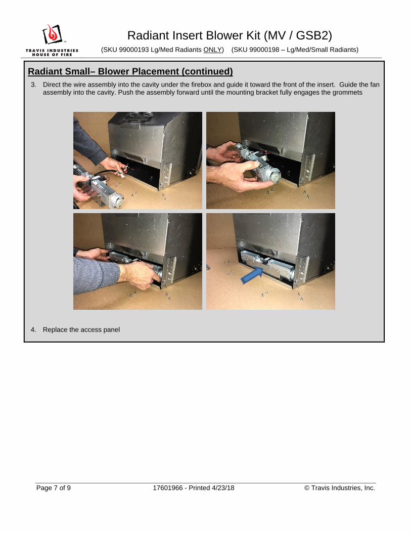
Radiant Small– Blower Placement (continued) 3. Direct the wire assembly into the cavity under the firebox and guide it toward the front of the insert. Guide the fan
assembly into the cavity. Push the assembly forward until the mounting bracket fully engages the grommets
4. Replace the access panel

Radiant Insert Blower Kit (MV / GSB2) (SKU 99000193 Lg/Med Radiants ONLY) (SKU 99000198 – Lg/Med/Small Radiants)
Page 8 of 9 17601966 - Printed 4/23/18 © Travis Industries, Inc.
5. Find the end of the wire harness attached to the blower assembly. Attach the right angle flag connectors to the snap disk (Polarity does not matter). The remaining two red connectors attach to the two rheostat wires (polarity does not matter). The green wire attaches to the grounding tab on the left side of the rheostat box.
To grounding
tab
Flag connectors
to snap disk
Grounding tab
To rheostat
wires
To power in

Radiant Insert Blower Kit (MV / GSB2) (SKU 99000193 Lg/Med Radiants ONLY) (SKU 99000198 – Lg/Med/Small Radiants)
Page 9 of 9 17601966 - Printed 4/23/18 © Travis Industries, Inc.
6. Connect the blower assembly to power (see below).
MV units GSB units
The Molex on the blower wire harness attaches to the Molex on the rheostat assembly.
The Molex on the Electrical Controls Assembly attaches to the Molex on the rheostat assembly. There is an additional Molex that comes off of the Electrical Controls Assembly that will attach the Molex on the blower wire harness.
7. Attach the Rheostat Box to the mounting bracket using the remaining two screws.
8. Verify no wires are touching firebox bottom, adjust if necessary.
9. Re-install the Glass Assembly.
GSB2 Units Only – Replace Electronic Controls Assembly Re-install the Electronic Controls Assembly into the unit (see page 2). Make sure the main connector fully engages with the connector from the valve.
10. Plug blower in and burn the appliance to verify operation. The blower will turn on after the appliance reaches operating temperature, typically 5 to 10 minutes after startup on high.
Power in
Attaches to rheostat
assembly Molex
Attaches to
blower Molex