Radiant Chambers for Fast Cook- Off Testing and …...Radiant Chambers for Fast Cook- Off Testing...
24
Gun and Electric Weapon Systems (E) NSWCDD-PN-18-00173; Distribution Statement A: Approved for Public Release; distribution is unlimited Radiant Chambers for Fast Cook-Off Testing and Simulation Jon J. Yagla, PhD and Joseph Plaia, PhD Paper No. 20262 2018 Insensitive Munitions and Energetic Materials Technology Symposium Portland, Oregon USA April 2018
Transcript of Radiant Chambers for Fast Cook- Off Testing and …...Radiant Chambers for Fast Cook- Off Testing...
Gun and Electric WeaponSystems (E)
NSWCDD-PN-18-00173; Distribution Statement A: Approved for Public Release; distribution is unlimited
Radiant Chambers for Fast Cook-Off Testing and Simulation
Jon J. Yagla, PhD and Joseph Plaia, PhD
Paper No. 20262
2018 Insensitive Munitions and Energetic Materials Technology Symposium
Portland, Oregon USA
April 2018
Radiant Chamber and Data Acquisition Equipment
GUN & ELECTRIC WEAPON SYSTEMS DEPARTMENTNSWCDD-PN-18-00173; Distribution Statement A: Approved for Public Release
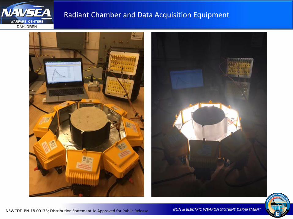
Radiant Chamber and Data Acquisition Equipment
GUN & ELECTRIC WEAPON SYSTEMS DEPARTMENTNSWCDD-PN-18-00173; Distribution Statement A: Approved for Public Release
• Two radiant chambers built and tested
• Uniform radiation field for testing small items
• Calibrated with thermocouple rakes and calorimeters
Used to test instruments before putting them in large fuel fires
Highly controlled laboratory data for development of computer simulations
Explaining experimental data from equipment being tested during development

Organization of the Paper
GUN & ELECTRIC WEAPON SYSTEMS DEPARTMENTNSWCDD-PN-18-00173; Distribution Statement A: Approved for Public Release
Calibrating the chambers
Checking and calibrating instruments
Checking and calibrating for test items
Testing a rocket motor
GUN & ELECTRIC WEAPON SYSTEMS DEPARTMENTNSWCDD-PN-18-00173; Distribution Statement A: Approved for Public Release
Temperature and Heat Flux Calibration

Temperature Around Circumference of Calorimeter
GUN & ELECTRIC WEAPON SYSTEMS DEPARTMENTNSWCDD-PN-18-00173; Distribution Statement A: Approved for Public Release
Calorimeter for showing angular uniformity of temperature
Nine locations radiated by eight lamps
Circumferential variation should be detected
Very little variation around the circumference

Temperature Variation in the Axial Direction Along the Calorimeter
GUN & ELECTRIC WEAPON SYSTEMS DEPARTMENTNSWCDD-PN-18-00173; Distribution Statement A: Approved for Public Release
Temperature at three axial locations
Measurements inside and outside of the calorimeter
The temperature verses time traces on one line

Heat Flux Calibration
GUN & ELECTRIC WEAPON SYSTEMS DEPARTMENTNSWCDD-PN-18-00173; Distribution Statement A: Approved for Public Release
Absorbed heat flux 30.4 kW/m
Spans range of the heat flux for encanistered missiles
GUN & ELECTRIC WEAPON SYSTEMS DEPARTMENTNSWCDD-PN-18-00173; Distribution Statement A: Approved for Public Release
Checking and Calibrating Instruments

Differential Flame ThermometerBeing Checked Out in Radiant Chamber
GUN & ELECTRIC WEAPON SYSTEMS DEPARTMENTNSWCDD-PN-18-00173; Distribution Statement A: Approved for Public Release
Differential Flame Thermometer

Heat Flux Calibration with aLow-Emissivity Thermopile Calorimeter
GUN & ELECTRIC WEAPON SYSTEMS DEPARTMENTNSWCDD-PN-18-00173; Distribution Statement A: Approved for Public Release
Note the good agreement with 30.4 kW/m2 in the calibration section

GUN & ELECTRIC WEAPON SYSTEMS DEPARTMENTNSWCDD-PN-18-00173; Distribution Statement A: Approved for Public Release
Variable Transformer Allows Adjustment of Heat Flux
GUN & ELECTRIC WEAPON SYSTEMS DEPARTMENTNSWCDD-PN-18-00173; Distribution Statement A: Approved for Public Release
Magazine Safety Test

Buildup for Fast-Heating Test of Rocket Motor
GUN & ELECTRIC WEAPON SYSTEMS DEPARTMENTNSWCDD-PN-18-00173; Distribution Statement A: Approved for Public Release
Empty Rocket Motor Casing Motor Case Filled with Inert Propellant
Full Setup with Instrumentation
• Section of a real test motor• Inert propellant simulant • TCs along five thermal paths to propellant• TCs on outer casing, between case and insulation, between the insulation
and the propellant
Temperature Data Recorded During Heating in Chamber
GUN & ELECTRIC WEAPON SYSTEMS DEPARTMENTNSWCDD-PN-18-00173; Distribution Statement A: Approved for Public Release
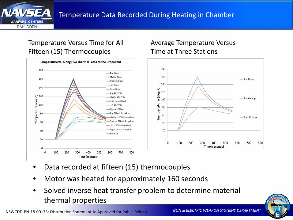
Temperature Versus Time for All Fifteen (15) Thermocouples
Average Temperature Versus Time at Three Stations
• Data recorded at fifteen (15) thermocouples• Motor was heated for approximately 160 seconds• Solved inverse heat transfer problem to determine material
thermal properties
Computational Model Development
GUN & ELECTRIC WEAPON SYSTEMS DEPARTMENTNSWCDD-PN-18-00173; Distribution Statement A: Approved for Public Release
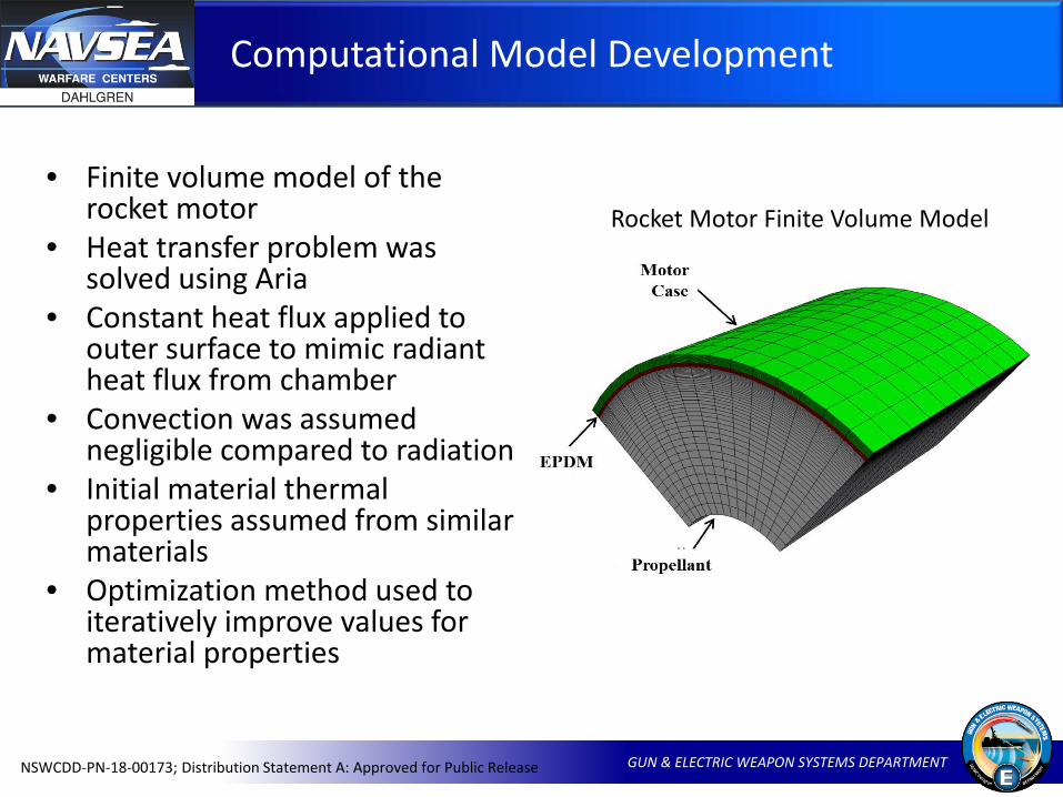
• Finite volume model of the rocket motor
• Heat transfer problem was solved using Aria
• Constant heat flux applied to outer surface to mimic radiant heat flux from chamber
• Convection was assumed negligible compared to radiation
• Initial material thermal properties assumed from similar materials
• Optimization method used to iteratively improve values for material properties
Rocket Motor Finite Volume Model
Material Property Optimization
GUN & ELECTRIC WEAPON SYSTEMS DEPARTMENTNSWCDD-PN-18-00173; Distribution Statement A: Approved for Public Release
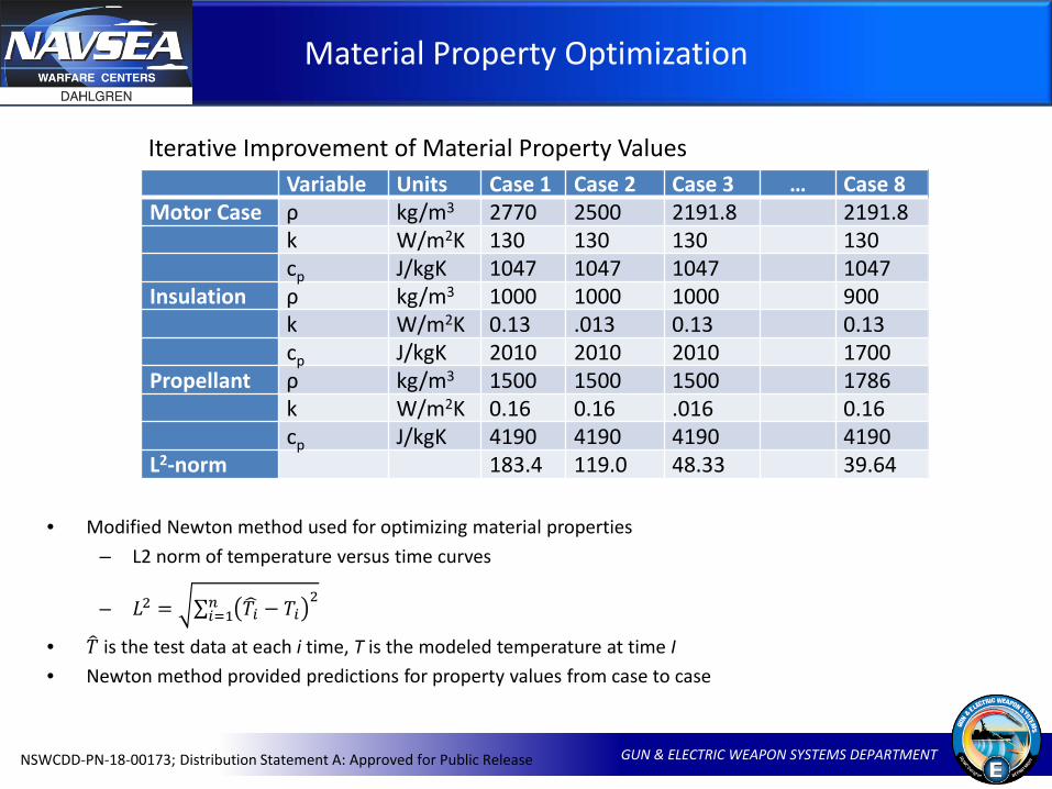
Iterative Improvement of Material Property ValuesVariable Units Case 1 Case 2 Case 3 … Case 8
Motor Case ρ kg/m3 2770 2500 2191.8 2191.8k W/m2K 130 130 130 130cp J/kgK 1047 1047 1047 1047
Insulation ρ kg/m3 1000 1000 1000 900k W/m2K 0.13 .013 0.13 0.13cp J/kgK 2010 2010 2010 1700
Propellant ρ kg/m3 1500 1500 1500 1786k W/m2K 0.16 0.16 .016 0.16cp J/kgK 4190 4190 4190 4190
L2-norm 183.4 119.0 48.33 39.64
• Modified Newton method used for optimizing material properties– L2 norm of temperature versus time curves
– 𝐿𝐿2 = ∑𝑖𝑖=1𝑛𝑛 �𝑇𝑇𝑖𝑖 − 𝑇𝑇𝑖𝑖2
• �𝑇𝑇 is the test data at each i time, T is the modeled temperature at time I• Newton method provided predictions for property values from case to case
Optimized Material Properties
GUN & ELECTRIC WEAPON SYSTEMS DEPARTMENTNSWCDD-PN-18-00173; Distribution Statement A: Approved for Public Release
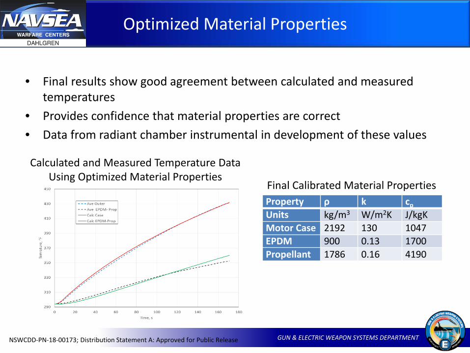
• Final results show good agreement between calculated and measured temperatures
• Provides confidence that material properties are correct• Data from radiant chamber instrumental in development of these values
Calculated and Measured Temperature Data Using Optimized Material Properties
Final Calibrated Material PropertiesProperty ρ k cpUnits kg/m3 W/m2K J/kgKMotor Case 2192 130 1047EPDM 900 0.13 1700Propellant 1786 0.16 4190

Rocket Motor Restrained Firing Model
GUN & ELECTRIC WEAPON SYSTEMS DEPARTMENTNSWCDD-PN-18-00173; Distribution Statement A: Approved for Public Release
• During RF test, TCs were covered with thermal cement with known properties
• Cement included in model with other three layers
• Thermal properties of other materials determined using radiant chamber data
• Thickness of cement was estimated, and multiple cases were run to determine sensitivity of results to cement thickness
Finite Volume Model of Rocket Motor with Thermocouple Under Cement
Cut-Away View of Temperature Predicted for One Case at 3.1 Seconds After Motor Ignition
Check for Rocket Motor FCO
GUN & ELECTRIC WEAPON SYSTEMS DEPARTMENTNSWCDD-PN-18-00173; Distribution Statement A: Approved for Public Release
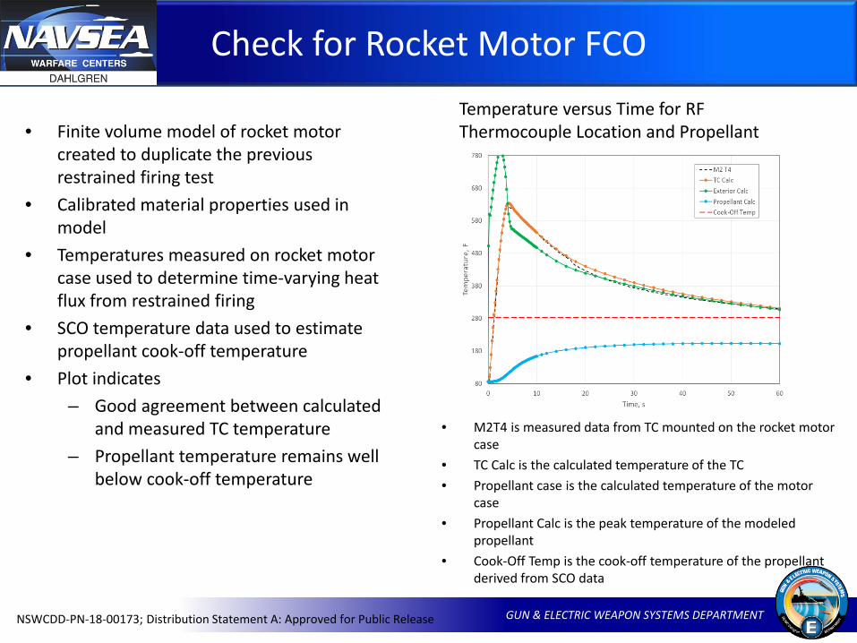
• Finite volume model of rocket motor created to duplicate the previous restrained firing test
• Calibrated material properties used in model
• Temperatures measured on rocket motor case used to determine time-varying heat flux from restrained firing
• SCO temperature data used to estimate propellant cook-off temperature
• Plot indicates – Good agreement between calculated
and measured TC temperature– Propellant temperature remains well
below cook-off temperature
Temperature versus Time for RF Thermocouple Location and Propellant
• M2T4 is measured data from TC mounted on the rocket motor case
• TC Calc is the calculated temperature of the TC• Propellant case is the calculated temperature of the motor
case• Propellant Calc is the peak temperature of the modeled
propellant• Cook-Off Temp is the cook-off temperature of the propellant
derived from SCO data
Summary and Conclusions
GUN & ELECTRIC WEAPON SYSTEMS DEPARTMENTNSWCDD-PN-18-00173; Distribution Statement A: Approved for Public Release
• Radiant chambers have been built to simulate the radiant heating in fast cook-off fires
• The radiant chambers show good axial and circumferential uniformity in temperature
• The chambers provide a broad range of heat fluxes which easily span the range of heat flux into propellant in enclosed systems (20–25 kW/m2)
• The heat flux is in the range for developing enclosed systems to qualify under STANAG 4240
• The chambers have been used for testing instruments and test items prior to exposure to fires
• The chambers have been used to solve complex problems in fast cook-off and Navy launcher safety testing

Backup
GUN & ELECTRIC WEAPON SYSTEMS DEPARTMENTNSWCDD-PN-18-00173; Distribution Statement A: Approved for Public Release
Introduction
GUN & ELECTRIC WEAPON SYSTEMS DEPARTMENTNSWCDD-PN-18-00173; Distribution Statement A: Approved for Public Release
Two radiant chambers have been built and tested. They provide a uniform radiation field for testing small items. They have been calibrated with thermocouple rakes and cylindrical steel calorimeters. The radiation fields are unexpectedly uniform and have axial and circumferential uniformity. The chambers use eight 250-Watt cylindrical halogen bulbs. The bulbs are enclosed in inexpensive work light housings readily available at home centers. A variac has been used to control the heat flux. Since fast cook heating of test items is 90% radiative, the chambers provide good tests for many items.
The chambers have been used to test instruments before putting them in large fuel fires. They have also been used to obtain highly controlled laboratory data for development of computer simulations, explaining experimental data from equipment being tested during development, and converging computer simulations when there was uncertainty in material property data.
Calibration data are presented along with results from testing a 7-inch (180 mm) rocket motor chamber with insulation and simulated propellant. Temperature versus time data was recorded by fifteen (15) thermocouples to measure the heat flow along each of five thermal paths from the outer surface of the motor, through the insulation, and into the propellant. The data were used to resolve problems caused by uncertainty in property data for the motor chamber and insulation in a finite element model used to analyze a restrained firing of a missile in a shipboard launcher.
Introduction, continued
GUN & ELECTRIC WEAPON SYSTEMS DEPARTMENTNSWCDD-PN-18-00173; Distribution Statement A: Approved for Public Release
The chambers have been used to test instruments before putting them in large fuel fires. They have also been used to obtain highly controlled laboratory data for development of computer simulations, explaining experimental data from equipment being tested during development, and converging computer simulations when there was uncertainty in material property data.
Calibration data are presented along with results from testing a 7-inch (180 mm) rocket motor chamber with insulation and simulated propellant. Temperature versus time data was recorded by fifteen (15) thermocouples to measure the heat flow along each of five thermal paths from the outer surface of the motor, through the insulation, and into the propellant. The data were used to resolve problems caused by uncertainty in property data for the motor chamber and insulation in a finite element model used to analyze a restrained firing of a missile in a shipboard launcher.