RADIAL VENTILATOREN, MCF Serie für LUFT, BIOGAS … · CENTRIFUGAL FANS, MCF Series, for BIOGAS...
10
RADIAL VENTILATOREN, MCF Serie für LUFT, BIOGAS und ERDGAS gemäß der Richtlinie 94/9/EG (ATEX) CENTRIFUGAL FANS, MCF Series, for AIR, for BIOGAS and NATURAL GAS in conformity with 94/9/EC Directive (ATEX) ®
Transcript of RADIAL VENTILATOREN, MCF Serie für LUFT, BIOGAS … · CENTRIFUGAL FANS, MCF Series, for BIOGAS...

RADIAL VENTILATOREN, MCF Seriefür LUFT, BIOGAS und ERDGASgemäß der Richtlinie 94/9/EG (ATEX)
CENTRIFUGAL FANS, MCF Series,for AIR, for BIOGAS and NATURAL GASin conformity with 94/9/EC Directive (ATEX)
®

CENTRIFUGAL FANS, MCF Series, for BIOGAS and NATURAL GAS
2
MAP
RO
Funktion Die MAPRO® Radial Ventilatoren der MCF Serie bestehen:- aus einem Ansaugkanal, der das angesaugte Gas zum Eingang des Laufrades koaxial zur Welle befördert;- aus einem geschlossenen Laufrad mit axialen Eingang und radialen Ausgang;- aus einem Ringkanal mit tangentialem Ausgang.Durch die Drehung des Laufradeswird das Gas in den Schaufelndes Laufrades verwirbelt und nachaußen in den Ringkanal geschleudert.Die kinetische Energie wird dabei erhöhtund ermöglicht dadurch den Druckaufbau.Im Ringkanal sammelt sich das Gas undwird über den tangential angeordnetenAusgangsflansch nach außen geführt.
VorteileDa die rotierenden Teile das Gehäuse nicht berühren, gibt es auch keine Reibungsverluste. Folglich ist auch keine Schmierung erforderlich und der Verdichtungsvorgang erfolgt absolut ölfrei.Eine Verunreinigung des Gases findetnicht statt.Weitere Vorteile der MAPRO® MCF Radial Ventilatoren sind:• einfache Installation;• geringer Schalldruckpegel;• vibrationsfrei;• keine Pulsation des Fördermediums;• geringer Wartungsaufwand.
Für entflammbare Gase, wie Erd- und Biogase, wurde eigens eine Produktlinie für die MAPRO® MCF Radial Ventilatoren mit einer speziellen Herstellungstechnologie entwickelt. Diese wird mit der Handelsmarke
gekennzeichnet. Somit hebt diese Handelsmarke die Ventilatoren zur Förderung und Verdichtung dieses Gases deutlich hervor.
RADIAL VENTILATOREN, MCF Serie, für BIOGAS und ERDGAS
Operating principle The MAPRO® centrifugal fans, MCF Series, are made of: - an intake duct conveying the aspirated gas to the impeller inlet that is coaxial to the shaft; - a closed impeller with axial flow inlet and radial flow exit; - a toroidal discharge volute with tangential exit. While the impeller is rotating, the vanes give a centrifugal thrust to the aspirated gas which is forced outwards into the toroidal discharge volute. The volute collects the gas delivering it to a tangential nosepiece. The compression occurs through the increment of kinetic energy given to the gas by the vanes of the impeller and the subsequent conversion of the kinetic energy into static pressure in the discharge volute.
AdvantagesThe rotating parts are not in contact with the casing during rotation. There is therefore no friction during operation and thus no internal lubrication is necessary. The gas moving through the machine remains uncontaminated and completely oil-free. The other main advantages of using the MAPRO® MCF centrifugal fans are: • easy installation; • low noise level; • no vibration; • pulsation free gas flow and no surge; • minimal maintenance.
For the mixtures of combustible gases, such as biogas and natural gas, MAPRO® has chosen to feature the specific manufacturing technology used for the MCF centrifugal fans with the trademark
that highlights their design expressly worked out for the extraction and compression of these gases.

3
MAP
RO
Allgemeine und konstruktiveLösungen gemäß der Richtlinie94/9/EG (ATEX)Die MAPRO® MCF Radial Ventilatoren sind für die Verdichtung von brennbaren Gasen, wie Biogas oder Erdgas, entwickelt worden. Sie entsprechen im Inneren als auch in der umgebenen Zone der Gerätegruppe II gemäß der Richtlinie 94/9/EG (ATEX), Kategorie 2. Sie sind Maschinen die über folgende besondere Konstruktionsmerkmale verfügen:• das Gehäuse und das Laufrad sind vollständig aus einer funkengeschützter Aluminiumlegierung gefertigt;• das Laufrad ist geschlossen und die Schaufeln des Laufrades wurden zwischen den beiden Laufradscheiben aus Aluminium sicher und dauerhaft eingepresst;• das Lagergehäuse besteht aus Gusseisen, der Lagerdeckel aus einer Aluminiumlegierung und die Antriebswelle aus Stahl;• das Gehäuse ist mit Loctite imprägniert;• die Gehäusehälften sind versiegelt;• zwei doppelt wirkende spezielle Wellendichtringe sorgen für
eine Dauerschmierung bis zu einer Drehzahl von 4.200 U/min.Bei höheren Drehzahlen wird eine automatische arbeitendeSchmierfettpatrone eingesetzt.
Die Radial Ventilatoren sind im Allgemeinen mit dem Elektromotor über einen Riemenantrieb verbunden. Ein funkenfreies Schutzgitter dient als Berührungsschutz. MAPRO® Radialventilatoren sind auch mit flexiblen Wellenkupplungen oder in der sogenannten „KOMPAKTVERSION“ (MCF...CC typ) lieferbar. Bei der „KOMPAKTVERSION“ ist der Elektromotor direkt am Gehäuse des Verdichters befestigt. Das dynamisch ausgewuchtete Laufrad ist dabei direkt an der Motorwelle angeflanscht.Wird der Einsatzbereich als Zone 1 klassifiziert, werden die Elektromotoren in der explosionsgeschützten Ausführung, Schutzart “d”, mit einer spezifischer Kennzeichnung Ex II 2 G versehen und zusätzlich mit Ex-d IIB T3 gekennzeichnet.Wird der Einsatzbereich als Zone 2 klassifiziert, in der Geräte der Gerätegruppe II, Kategorie 3, zugelassen sind, können die Elektromotoren in einer funkenfreier Ausführung geliefert werden. Diese haben die Schutzart “n”, mit spezifischer Kennzeichnung Ex II 3 G, zusätzliche Kennzeichnung Ex-nA II T3.
Generalities and construction features in conformity with the 94/9/EC Directive (ATEX)The MAPRO® centrifugal fans, MCF Series, to be used for extraction or compression of combustible gases, such as biological or natural gas, have been designed in order to fall within the Equipment-Group II as defined by the 94/9/EC Directive (ATEX), Category 2 both for the surrounding area conditions and for the internals of the machine. Their main construction features are the following:
• aluminium casted casing, impeller made of spark proofaluminium alloy with caulked vanes, bearings housing made in cast iron and with aluminium casted caps, shaft in carbon steel;
• casing impregnated with Loctite;• casing halves sealed;• shaft sealing by a pair of special life-lubricated
double-lip seals for speed of rotation up to 4200 rpm;for higher rpm lubrication is provided by an automatic
lubricator.
The centrifugal fans are generally coupled to the electric motor via belt drive and the safety drive guard is made of spark-free material.We can also offer machines coupled to the electric motor via flexible shaft coupling and centrifugal fans manufactured in the so-called “CLOSE COUPLED” version (MCF...CC type) – i.e. a flange mounted electric motor is bolted to the fan casing and the impeller, which is dynamically balanced, is fitted directly onto the motor shaft extension.If the area surrounding the equipment is classified as Zone 1, the electric motors are flameproof, type of protection “d”, with specific marking Ex II 2 G, additional marking Ex-d IIB T3.If the area surrounding the equipment is classified as Zone 2, where, for the Group II, Category 3 equipments are accepted, the machine could be equipped with the type of protection “n” non-sparking motor, with specific marking Ex II 3 G, additional marking Ex-nA II T3.

MAP
RO
4
Auch für besondere Anwendungen und für besondere Gaszusammensetzungen können die Radialventilatoren eingesetzt werden. Zum Beispiel lässt sich das Innere des Ventilators mit einer anodischen Oxidation beschichten. Das Laufrad und die Schaufeln können auch aus Edelstahl gefertigt werden. Sollte die Abdichtung mit einer Sperrflüssigkeit erforderlich sein, ist auch dies möglich.
Allgemeine Anwendungen• Befüllung und Absaugung von Gasspeichern, Förderung von Biogas, Erdgas, Klärgas, Deponiegas, etc. zu einem Brenner oder Gasmotor;• Gasabsaugung aus Behältern oder Anlagen, Förderung zu einer Fackel oder Brenner; • Gastransfer von Biogasanlagen, zu Satelliten-BHKWs.Die MAPRO® Radial Ventilatoren sind für die erwähnten Anwendungen und für variable Gasvolumenströme die optimale Maschinen. Da die Kennlinie, bei fester Drehzahl, über einen weiten Bereich sehr flach ist, kann das Gebläse schnell auf Volumenstromänderungen reagieren.
ZubehörFolgendes Zubehör kann ebenfalls geliefert werden:• gasdichte Filter;• Kompensatoren aus Edelstahl mit Flanschanschluss;• Rückschlagventile;• Druck- und Temperaturanzeigegeräte;• Druckschalter und Thermostate in explosionsgeschützter Ausführung;• eigensichere Druck- und Temperaturmessumformer;• manuelle und automatische Absperrventile;• Schallschutzhauben.Die MAPRO® Vertriebsabteilung bietet auchSonderlösungen fürKunden an, die in engerZusammenarbeit mit der technischenAbteilung ausgearbeitet werden.
For particular duties and/or in function of the gas composition, fans with special construction features could be proposed; for example with the aluminium casted parts treated with anodic oxidation and the blades of the impeller in stainless steel; and it is also possible to fit the pair of double-lip seals on the shaft so that they are suitable for a barrier fluid in between.
The most common fields of application• Extraction of biogas from gasometer, natural gas from pipeline or gasometer, and burner or gas engine feeding;• tank or plant gas recovery to feed torch or burner; • biogas transfer from the production plant to remote satellite CHP units. The typical “flow rate – pressure” curve, rather flat at fixed rpm, and the absence of surging when decreasing the gas flow, make the MAPRO® centrifugal fans the ideal machines for all the applications in which the gas flow rate could vary, even considerably. In fact, as the “flow rate - pressure” curve is quite flat on a large range of duty, the fan can immediately and safely react to the flow variations.
AccessoriesA complete range of accessories is available, including the following:• gas-tight filters;• stainless steel flanged flexible connection bellows;• non return valves;• pressure gauges and thermometers;• explosion-proof pressure switches and temperature switches;
• intrinsically-safe pressure and temperature transducers;• manual and automatic cut-off valves;• acoustic enclosures.MAPRO® Sales Department, in synergy with the Engineering Department, could design and quote, according to customer requirements, the machines complete with the accessories that better meet the specific needs and peculiarities of the plant.

AbmessungenRiemenantrieb Version
„KOMPAKTVERSION“
DimensionsBelt drive version
“CLOSE COUPLED” version
MAP
RO
5
Eingangs- und Ausgangsflansch:Inlet and outlet flanges: PN16 DN125 EN1092-1/01/A
Eingangs- und Ausgangsflansch:Inlet and outlet flanges: PN16 DN125 EN1092-1/01/A
G= H =
NB
==D ==EF
IM
C
A
4 BOHRUNGEN-HOLES 20 H
NC
DE
A
B
P
L
I
=G
== =
1/2”GAS
F
OM
DIE AUTOMATISCHE SCHMIERUNG IST NUR FÜR DREHZAHLEN > 4200 U/min ERFORDERLICHAUTOMATIC LUBRICATOR ONLY FOR SPEED > 4200rpm>
VentilatortypFan Type A B(*) C D E F G H I L M N
GewichtWeight[kg](*)
MCF 390 CC 687 600 615 290 390 212 249 209 132 203 335 64MCF 500 CC 797 622 719 400 500 212 289 209 132 258 390 39 82
59
Abmessungen [mm](*)Abmessung B und Gewicht mit Elektromotor Ex II 2G 2,2kW
Dimensions [mm](*)Dimension B and weight with Ex II 2G 2,2kW motor
VentilatortypFan Type A B(*) C D E F G H I L M N O P
GewichtWeight[kg](*)
MCF 390 1300 580 675 1150 1210 90 550 450 405 183 348 205MCF 500 1360 675 800 1150 1210 150 550 450 460 183 367 202 340
202 203 407258 462
Abmessungen [mm](*)Abmessung B und Gewicht mit der größtmöglichen Ex II 2G Motorstärke
Dimensions [mm](*)Dimension B and weight with the largest Ex II 2G motor power
L
1/2”GAS
4 BOHRUNGEN-HOLES 18

6
MAP
RO
Volumenstrom [m3/h]Flow rate [m3/h]
Druc
kdiff
eren
z (Üb
erdr
uck)
[hPa
= m
bar]
Outle
t pre
ssur
e
[hPa
= m
bar]
200 6004000 800 12001000 1400 18001600 2000 24002200 2600 2800 3000
20
40
60
80
100
120
140
160
180
18,5 kW - 83 dB(A) bei/at 1m
9 kW - 81 dB(A) bei/at 1m
1,5 kW(*) - 72 dB(A) bei/at 1m
2,2 kW(*) - 72 dB(A) bei/at 1m
Einsatzbereich der MCF für Biogas MCF for biogas – Range of duty
(*) für „KOMPAKTVERSION“ for “CLOSE COUPLED” version
200 6004000
800 12001000 1400 18001600 2000 24002200 2600
20
40
60
80
100
120
Volumenstrom [m3/h]Flow rate [m3/h]
Druc
kdiff
eren
z (Üb
erdr
uck)
[hPa
= m
bar]
Outle
t pre
ssur
e
[hPa
= m
bar]
9 kW - 80 dB(A) bei/at 1m
4 kW - 78 dB(A) bei/at 1m
1,5 kW(*) - 69 dB(A) bei/at 1m
2,2 kW(*) - 69 dB(A) bei/at 1m
(*) für „KOMPAKTVERSION“ for “CLOSE COUPLED” version
MCF 500
MCF 390
6250 U/min-rpm5800 U/min-rpm5350 U/min-rpm4800 U/min-rpm
4200 U/min-rpm3600 U/min-rpm2950 U/min-rpm
5800 U/min-rpm5350 U/min-rpm4800 U/min-rpm
4200 U/min-rpm3600 U/min-rpm
2950 U/min-rpm

MAP
RO
7
Typ JahrType YearSeriennummer Technischen UnterlagenSerial number Technical file
II2G c IIBT3
NNNNN 94/9-MCF
MCF XXX G YYYY
RADIAL VENTILATOR - CENTRIFUGAL FAN
Via E. Fermi, 3 - 20834 NOVA MILANESE - (MB) - ITALY
Tel. +39 0362.366356 - Fax +39 0362.450342
www.maproint.com - [email protected] MADE IN ITALY
MAPRO INTERNATIONAL S.p.A.®
KategorieCategory
GerätegruppeEquipment group
GerätegruppeEquipment group
GerätegruppeEquipment group
ZündschutzartType of ignition protection
ZündschutzartType of ignition protection
ZündschutzartType of ignition protection
GasgruppeGas group
TemperaturklasseTemperature class
TemperaturklasseTemperature class
TemperaturklasseTemperature class
Identifikationsnummer der technischen MAPRO Unterlage,die in der benannten Stelle ICIM (0425) eingetragen istIdentification number of the MAPRO Technical File communicated to the Notified Body ICIM (0425)
KategorieCategory
GasgruppeGas group
Die ATEX Kennzeichnung der MAPRO® MCF Radial Ventilatoren für Biogas oder ErdgasThe ATEX marking of the MAPRO® centrifugal fans, MCF Series, for biogas or natural gas
{ {
{ {{ {
Typ JahrType YearSeriennummer Technischen UnterlagenSerial number Technical file
umliegender Bereich - surrounding areainnerer Bereich - fan inside
NNNNN 94/9-MCF
RADIAL VENTILATOR - CENTRIFUGAL FAN
II2G c IIBT3
MADE IN ITALY
MAPRO INTERNATIONAL S.p.A. Via E. Fermi, 3 - 20834 NOVA MILANESE - (MB) - ITALY
Tel. +39 0362.366356 - Fax +39 0362.450342
www.maproint.com - [email protected]
II3G c IIBT3
MCF XXX G YYYY
®
KategorieCategory
GasgruppeGas group
Einsatzbereich der MCF für Biogas
Das Einsatzbereich wie in den Abbildungen der vorherigen Seite gezeigt bezieht sich auf Biogas mit einem spezifischen Gewicht von 1,14kg/Nm³. Der Saugdruck wird mit 1013 mbar abs. und die Saugtemperatur mit 35°C angesetzt.Die dargestellten Leistungskurven „Volumenstrom - Druckdifferenz“ werden exemplarisch innerhalb des Leistungsumfanges mit fester Drehzahl gezeigt.Sowohl die untere als auch die obere Leistungskurve enthalten Informationen über die erforderliche Motorleistung und den Schalldruckpegel.Die Kurve mit den Drehzahlen von 2950 U/min zeigt die Motorleistungen der MCF in der sogenannten „KOMPAKTVERSION“ (typ MCF...CC).Bei höheren Drehzahlen werden die MCFgrundsätzlich mit Riemenantrieb ausgerüstet.Der angegebene Schalldruckpegel wird nach dem Standard EN ISO 2151 bei 1 Meter Abstand gemessen.
In dem violett dargestellten Drehzahlbereich kann der Radialventilator auch in der preiswerten „KOMPAKTVERSION“ (typ MCF...CC) für Regelung mit Frequenzumrichter geliefert werden.
MCF for biogas – Range of duty
The range of duty shown in the diagrams on the previous page refers to a biogas with specific weight 1.14kg/Nm3. The suction pressure is assumed at 1013 mbar abs. and
the inlet temperature at 35°C. The performance curves “flow rate - outlet
pressure”, shown in the range of duty, are given, as an indication only, at fixed rpm. On the performance curves at the lowest and the highest speed of
rotation are shown, by way of information, some values of
motor power and machine noise level. The motor powers shown on the curves at 2950 rpm are intended for centrifugal fans in the so-called “CLOSE
COUPLED” version (MCF...CC type); those shown on the curves at the highest rpm are intended for fans coupled to the
electric motors via belt drives. The noise level is intended as sound
pressure level (SPL), measured in free field, in accordance with the Standard EN ISO 2151.
For the part in violet of the “range of duty” centrifugal fans manufactured in the so-called “CLOSE COUPLED” version (MCF...CC type)
and equipped with electric motors intended for control via frequency inverter could be supplied.
CENTRIFUGAL FANS, MCF Series, for AIR
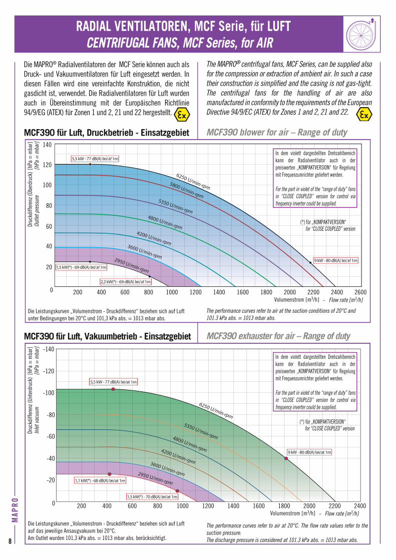
Die MAPRO® Radialventilatoren der MCF Serie können auch als Druck- und Vakuumventilatoren für Luft eingesetzt werden. In diesen Fällen wird eine vereinfachte Konstruktion, die nicht gasdicht ist, verwendet. Die Radialventilatoren für Luft wurden auch in Übereinstimmung mit der Europäischen Richtlinie 94/9/EG (ATEX) für Zonen 1 und 2, 21 und 22 hergestellt.
MCF390 für Luft, Druckbetrieb - Einsatzgebiet
Die Leistungskurven „Volumenstrom - Druckdifferenz“ beziehen sich auf Luftunter Bedingungen bei 20°C und 101,3 kPa abs. = 1013 mbar abs.
MCF390 für Luft, Vakuumbetrieb - Einsatzgebiet
Die Leistungskurven „Volumenstrom - Druckdifferenz“ beziehen sich auf Luftauf das jeweilige Ansaugvakuum bei 20°C. Am Outlet wurden 101,3 kPa abs. = 1013 mbar abs. berücksichtigt.
RADIAL VENTILATOREN, MCF Serie, für LUFT
The MAPRO® centrifugal fans, MCF Series, can be supplied also for the compression or extraction of ambient air. In such a case their construction is simplified and the casing is not gas-tight. The centrifugal fans for the handling of air are also manufactured in conformity to the requirements of the European Directive 94/9/EC (ATEX) for Zones 1 and 2, 21 and 22.
MCF390 blower for air – Range of duty
The performance curves refer to air at the suction conditions of 20°C and 101.3 kPa abs. = 1013 mbar abs.
MCF390 exhauster for air – Range of duty
The performance curves refer to air at 20°C. The flow rate values refer to the suction pressure. The discharge pressure is considered at 101.3 kPa abs. = 1013 mbar abs.
Volumenstrom [m3/h] - Flow rate [m3/h]
Druc
kdiff
eren
z (Üb
erdr
uck)
[hPa
= m
bar]
Outle
t pre
ssur
e[h
Pa =
mba
r]Dr
uckd
iffer
enz (
Unte
rdru
ck)
[hPa
= m
bar]
Inle
t vac
uum
[hPa
= m
bar]
Volumenstrom [m3/h] - Flow rate [m3/h]200 6004000 800 12001000 1400 18001600 2000 24002200 2600
20
40
60
80
100
120
140
5,5 kW - 77 dB(A) bei/at 1m
1,5 kW(*) - 69 dB(A) bei/at 1m
2,2 kW(*) - 69 dB(A) bei/at 1m
9 kW - 80 dB(A) bei/at 1m
5800 U/min-rpm5350 U/min-rpm
4800 U/min-rpm4200 U/min-rpm
3600 U/min-rpm2950 U/min-rpm
6250 U/min-rpm
200 6004000 800 12001000 1400 18001600 2000 24002200
-20
-40
-60
-80
-100
-120
-140
6250 U/min-rpm
5350 U/min-rpm4800 U/min-rpm4200 U/min-rpm3600 U/min-rpm2950 U/min-rpm
5,5 kW - 77 dB(A) bei/at 1m
1,1 kW(*) - 68 dB(A) bei/at 1m
1,5 kW(*) - 70 dB(A) bei/at 1m
9 kW - 80 dB(A) bei/at 1m
(*) für „KOMPAKTVERSION“ for “CLOSE COUPLED” version
In dem violett dargestellten Drehzahlbereich kann der Radialventilator auch in der preiswerten „KOMPAKTVERSION“ für Regelung mit Frequenzumrichter geliefert werden.
For the part in violet of the “range of duty” fans in “CLOSE COUPLED” version for control via frequency inverter could be supplied.
(*) für „KOMPAKTVERSION“ for “CLOSE COUPLED” version
MAP
RO
8
In dem violett dargestellten Drehzahlbereich kann der Radialventilator auch in der preiswerten „KOMPAKTVERSION“ für Regelung mit Frequenzumrichter geliefert werden.
For the part in violet of the “range of duty” fans in “CLOSE COUPLED” version for control via frequency inverter could be supplied.

MCF500 für Luft, Druckbetrieb - Einsatzgebiet
Die Leistungskurven „Volumenstrom - Druckdifferenz“ beziehen sich auf Luftunter Bedingungen bei 20°C und 101,3 kPa abs. = 1013 mbar abs.
MCF500 für Luft, Vakuumbetrieb - Einsatzgebiet
Die Leistungskurven „Volumenstrom - Druckdifferenz“ beziehen sich auf Luftauf das jeweilige Ansaugvakuum bei 20°C. Am Outlet wurden 101,3 kPa abs. = 1013mbar abs. berücksichtigt.
MCF500 blower for air – Range of duty
The performance curves refer to air at the suction conditions of 20°C and 101.3 kPa abs. = 1013 mbar abs.
MCF500 exhauster for air – Range of duty
The performance curves refer to air at 20°C. The flow rate values refer to the suction pressure. The discharge pressure is considered at 101.3 kPa abs. = 1013 mbar abs.
Volumenstrom [m3 /h] - Flow rate [m3 /h]
Druc
kdiff
eren
z (Üb
erdr
uck)
[hPa
= m
bar]
Outle
t pre
ssur
e[h
Pa =
mba
r]Dr
uckd
iffer
enz (
Unte
rdru
ck)
[hPa
= m
bar]
Inle
t vac
uum
[hPa
= m
bar]
Volumenstrom [m3 /h] - Flow rate [m3 /h]
MAP
RO
9
200 6004000 800 12001000 1400 18001600 2000 24002200 2600 2800 3000
180
20
40
60
80
100
120
160
140
9 kW - 81 dB(A) bei/at 1m
18,5 kW - 83 dB(A) bei/at 1m
2,2 kW(*) - 72 dB(A) bei/at 1m
1,5 kW(*) - 72 dB(A) bei/at 1m
(*) für „KOMPAKTVERSION“ for “CLOSE COUPLED” version
200 6004000 800 12001000 1400 18001600 2000 24002200 2600 2800 3000
-20
-40
-60
-80
-100
-120
-140
-160
9 kW - 81 dB(A) bei/at 1m
1,5 kW(*) - 72 dB(A) bei/at 1m
2,2 kW(*) - 72 dB(A) bei/at 1m
18,5 kW - 83 dB(A) bei/at 1m
(*) für „KOMPAKTVERSION“ for “CLOSE COUPLED” version
In dem violett dargestellten Drehzahlbereich kann der Radialventilator auch in der preiswerten „KOMPAKTVERSION“ für Regelung mit Frequenzumrichter geliefert werden.
For the part in violet of the “range of duty” fans in “CLOSE COUPLED” version for control via frequency inverter could be supplied.
In dem violett dargestellten Drehzahlbereich kann der Radialventilator auch in der preiswerten „KOMPAKTVERSION“ für Regelung mit Frequenzumrichter geliefert werden.
For the part in violet of the “range of duty” fans in “CLOSE COUPLED” version for control via frequency inverter could be supplied.
2950 U/min-rpm
5800 U/min-rpm5350 U/min-rpm
4800 U/min-rpm
4200 U/min-rpm3600 U/min-rpm
2950 U/min-rpm
5800 U/min-rpm5350 U/min-rpm
4800 U/min-rpm
4200 U/min-rpm
3600 U/min-rpm
COD. 0112 - MCF 06-16 D-GB
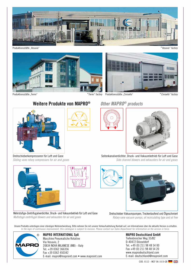
Drehschieberkompressoren für Luft und GaseSliding vane rotary compressors for air and gases
Seitenkanalverdichter, Druck- und Vakuumbetrieb für Luft und GaseSide channel blowers and exhausters for air and gases
Mehrstufige-Zentrifugalverdichter, Druck- und Vakuumbetrieb für Luft und GaseMultistage centrifugal blowers and exhausters for air and gases
Drehschieber-Vakuumpumpen, Trockenlaufend und ÖlgeschmiertRotary vane vacuum pumps, oil recirculating type and oil free
Weitere Produkte von MAPRO®
Unsere Produkte unterliegen einer ständigen Weiterentwicklung. Bitte nehmen Sie mit unserer Verkaufsabteilung Kontakt auf, um Informationen über die aktuelle Version zu erhalten.In the logic of continuous improvement, this catalogue is subject to revision. Please contact our Sales Department for information on the version in force.
Produktionsstätte „Vesuvio“ “Vesuvio” factory
Produktionsstätte „Fermi“ “Fermi” factory Produktionsstätte „Cinisello“ “Cinisello” factory
MAPRO INTERNATIONAL SpAMacchine Pneumatiche RotativeVia Vesuvio, 220834 NOVA MILANESE (MB) - ItalyTel. +39 0362 366356Fax +39 0362 450342E-mail: [email protected] • www.maproint.com
®
Other MAPRO® products
MAPRO Deutschland GmbHTiefenbroicher Weg 35/B2D-40472 DüsseldorfTel. +49 (0) 211 98 48 54 00 Fax +49 (0) 211 98 48 54 20www.maprodeutschland.com E-mail: [email protected]