Radial Shaft Seals - Ashton Seals
68
Radial Shaft Seals
Transcript of Radial Shaft Seals - Ashton Seals
Radial Shaft Seals

Contents Page
Parker Safety Guidelines 4
Rotary Seals - Introduction 5
Radial Shaft Seals 7
Contents
3Radial Shaft Seals Parker Hannifin GmbHPacking Division Europe
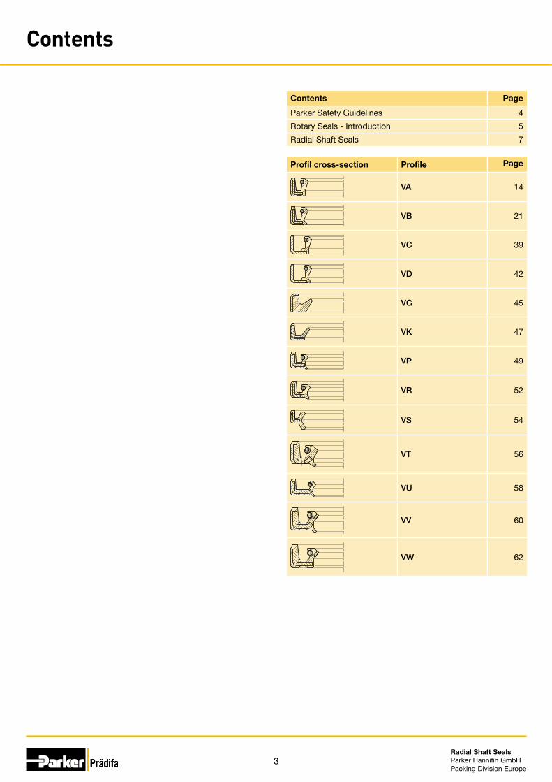
Profil cross-section Profile Page
VA 14
VB 21
VC 39
VD 42
VG 45
VK 47
VP 49
VR 52
VS 54
VT 56
VU 58
VV 60
VW 62
4Radial Shaft Seals Parker Hannifin GmbHPacking Division Europe
Parker Safety Guidelines
nor of knowing the composition of the operational media and cleaning agents used.
Design modifications
We reserve the right to make design modifications without prior notifi-cation.
Prototypes and samples
Prototypes and samples are produced from experimental moulds. The subsequent series production may differ in production techniques from the prototype production unless specific agreement to the contrary was reached beforehand.
Delivery and services
The delivery guarantee (availability of moulds) for individual dimensions of our range of products is limited to a period of 7 years.
Damaged moulds, including standard items, can only be replaced in case of sufficient demand. Most of the dimensions stated in this cata-logue are normally (but not as a matter of course) available ex stock.
For the production of smaller quantities, special compounds, and in case of special production procedures, we reserve the right of charging a prorated share of set-up costs.
All deliveries and services are subject to our terms.
Quality Systems
Our manufacturing sites are certified according to ISO 9001 resp. ISO/TS 16949.
Copyright
All rights reserved by Parker Hannifin GmbH. Extracts may only be taken with permission. Modification rights reserved.
Validity
This edition supersedes all prior documents.
Warning – User responsibility
This document and other information from Parker-Hannifin Corporation, its subsidiaries and authorized distributors provide product or system options for further investigation by users having technical expertise.
The user, through its own analysis and testing, is solely responsible for making the final selection of the system and components and as-suring that all performance, endurance, maintenance, safety and warn-ing requirements of the application are met. The user must analyze all aspects of the application, follow applicable industry standards, and follow the information concerning the product in the current product catalogue and in any materials provided from Parker or its subsidiaries or authorized distributors.To the extent that Parker or its subsidiaries or authorized distributors provide component or system options based upon data or specifica-tions provided by the user, the user is responsible for determining that such data and specifications are suitable and sufficient for all applica-tions and responsibly foreseeable uses of the components or systems.
Range of Application
Our seals may only be used within the application parameters stated in our documents as regards compatibility with contact media, pres-sures, temperatures and time of storage. Application or use outside of the specified application parameters as well as the selection of different compounds by mistake may result in damage to life, the environment and/or equipment and facilities.
The information contained in our publications is based on know-how developed over decades of experience in the manufacturing and ap-plication of seals. Despite this experience, unknown factors arising out of the practical application of seals may considerably affect the overall applicability of this information in such a way that the recommendations provided herein are not to be considered generally binding.
The data for working pressure, working temperature, and surface speed stated in the columns represent maximum values and are interrelated. Under extreme working conditions it is recommended not to use all maximum values simultaneously.
For special requirements (pressure, temperature, speed, etc.) please contact our Consultancy Service, so that suitable materials and/or de-signs can be recommended.
Compatibility of Seals and Operating Media / Cleaning Agents
Due to the great diversity of operational parameters affecting fluidic devices and their impact on seals, it is absolutely imperative that manu-facturers of these devices approve seals for functional and operational suitability under field conditions.
Furthermore, in view of the consistent increase of newly available media used as hydraulic oils, lubricants, and cleaning agents, special attention is invited to the aspect of compatibility with sealing elastom-ers currently in use.
Additives contained in base media in order to enhance certain func-tional characteristics may affect compatibility characteristics of sealing materials.
For this reason, it is imperative that any product equipped with our seals be tested for compatibility with operational media or cleaning agents approved or specified by you either at your plant or by means of field tests prior to any serial application.
We kindly ask you to comply with this notice since, as a manufacturer of seals, we are not in a position, as a matter of principle, to perform simu-lations regarding any and all conditions present in the final application
5Radial Shaft Seals Parker Hannifin GmbHPacking Division Europe
Rotary Seals – Introduction
between the sealing lip and the shaft when the system is in operation. When the shaft rotates, hydrodynamic proc-esses, which may lead to a slight pumping effect, sup-port the performance of the seal, particularly In case of radial shaft seals. Basic investigations by various universi-ties have confirmed this effect.
In case of other seal designs this lubrication is generated by a suitable contour in the area of the sealing lip.
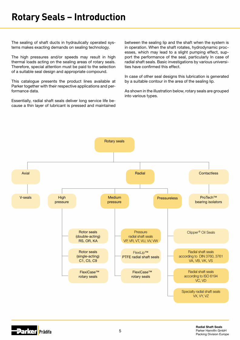
As shown in the illustration below, rotary seals are grouped into various types.
The sealing of shaft ducts in hydraulically operated sys-tems makes exacting demands on sealing technology.
The high pressures and/or speeds may result in high thermal loads acting on the sealing areas of rotary seals. Therefore, special attention must be paid to the selection of a suitable seal design and appropriate compound.
This catalogue presents the product lines available at Parker together with their respective applications and per-formance data.
Essentially, radial shaft seals deliver long service life be-cause a thin layer of lubricant is pressed and maintained
Rotary seals
Axial
V-seals PressurelessMedium pressure
High pressure
Rotor seals (double-acting)
RS, OR, KA
Pressure radial shaft seals
VP, VR, VT, VU, VV, VW
Clipper® Oil Seals
Rotor seals (single-acting)
C1, C5, C9
FlexiLip™PTFE radial shaft seals
Radial shaft seals according to DIN 3760, 3761
VA, VB, VK, VS
FlexiCase™rotary seals
FlexiCase™rotary seals
Radial shaft seals according to ISO 6194
VC, VD
Specialty radial shaft sealsVX, VY, VZ
ProTech™ bearing isolators
Radial Contactless
6Radial Shaft Seals Parker Hannifin GmbHPacking Division Europe
Rotary Seals – Introduction
The contact area of a rotary seal performs two essential functions. In most applications the contact area‘s primary function is to retain the bearing or system lubricant in the system to avoid leakage that would harm the environment. The relevant demands made on rotary seals by users and legislators are continually increasing. Furthermore, the large number of lubricants available on the market today poses particular challenges to seal manufacturers and seal users alike.
The second function of a rotary seal is to preclude any contamination of the system by external contaminants and to thereby prevent contamination of the lubricant and damage to the sensitive components in the system. The type of contamination depends on the particular applica-tion. Typical external contaminants include moisture and water as well as dry particles like dust, sand dirt or pro-duction residues.
Due to their ability to maintain the optimal amount of lu-bricant, to reduce frictional heat and to provide sealing against external contaminants rotary seals significantly affect the service life of all components which require lu-brication – such as bearings and gearboxes – and thus the service life of the entire system.
The sliding contact between the sealing lip or the sealing contour and the rotating shaft generates friction. This fric-tion may clearly increase the temperature beyond the level that is caused by the bearing and other components. The heat caused by friction accelerates the decomposition of the lubricant, particularly when mineral oils are used, and leads to the formation of deposits at the hot spots. Over time this results in an increasingly thick carbon layer with abrasive particles while the oil loses its lubricity. How fast the loss of lubricity occurs depends on the temperature. Particularly In case of radial shaft seals the carbon layer can lift or wear out the sealing lip, which ultimately leads to leakage. Experience has shown that the service life of a system can be cut in half by each 10 °C increase in tem-perature in the contact area. Consequently, a seal that would last for years in moderate conditions may fail within a very short period of time in case of significantly exces-sive temperatures.
The frictional heat generated when the seal operates may accelerate hardening of the elastomer compound or plas-tic, particularly in the contact area between the sealing lip and shaft. In case of NBR-based elastomer compounds this leads to axial cracks which become increasingly larg-er over time and ultimately result in seal failure.
Therefore, to maximize the service life of a rotary seal, as little frictional heat as possible should be generated in the contact area between the seal and the shaft surface.
The amount of frictional heat that is generated depends on numerous operating parameters. The type of shaft sur-face – including roughness and structure – operating pres-sure, surface speed, type of lubricant, seal geometry and seal material are just some of the factors to consider. The significant interactions between the individual parameters are of major importance as well. An increase in speed, for example, leads to a rise in oil temperature. Without ven-tilation, this temperature rise may lead to a pressure in-crease in the system. Higher pressure in turn puts a higher load on the seal, which results in additional forces acting between the sealing lip and the shaft. This results in a pro-gressive, significant increase in temperature underneath the sealing lip until premature seal failure occurs within a very short period of time.
To increase the service life of seals in rotary applications, a basic understanding of the functional principle of rotary seals is equally indispensable as extensive knowledge of the available seal types including their performance data and specific characteristics.
The Parker Seal Group continuously acquires and en-hances the relevant in-depth knowledge based on tests performed in its in-house physical lab and in the course of project work with external partners.
7Radial Shaft Seals Parker Hannifin GmbHPacking Division Europe
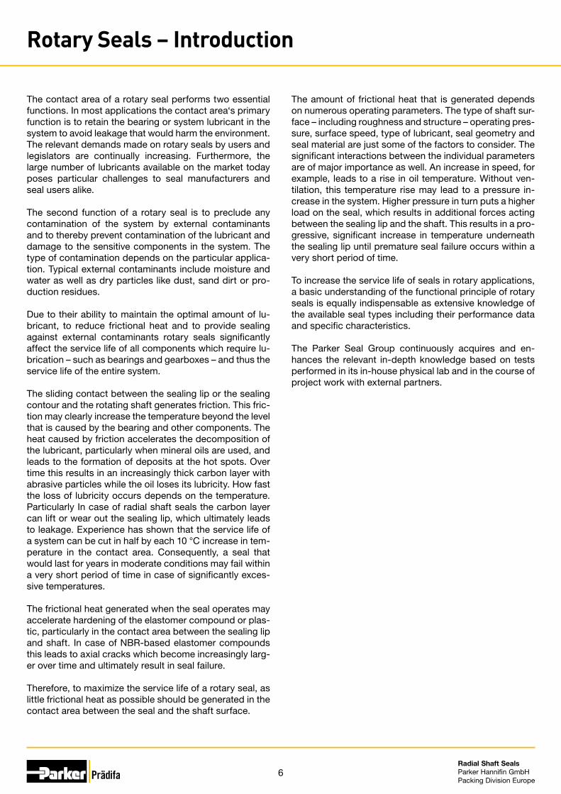
d D
a)
b)c)
d)
a)
Radial Shaft Seals
For decades, the radial shaft seal has been a widely used standard sealing element to seal rotating shafts in appli-cations with non-pressurised injection of lubricating oil or full submersion of the seal and shaft. Furthermore, in hy-draulic systems like pumps and motors special designs are used which enable reliable sealing of low or medium pressure differences. At the same time, these seals serve to prevent the intrusion of ambient dirt and water splash into the system. The sealing elements are used in hydrau-lic systems (hydraulic pumps and motors), industrial gear-boxes, washing machines, drills, wind turbines, the auto-motive industry and in a wide range of other applications in mechanical and equipment engineering. Radial shaft seals typically consist of a metal insert and an elastomer diaphragm with a spring-energised sealing lip. The sealing lip flex section is vulcanised to the metal insert inside the mould. The radial force of the sealing lip which is required for sealing is achieved by dilating the inner di-ameter in the area of the sealing edge of the radial shaft seal and via the inserted garter spring. The sealing lips of modern radial shaft seals have been designed to allow the seals to flexibly follow the radial motion of the rotating shaft without exerting an excessive radial force that may lead to increased friction and/or seal wear. Typically, the radial force related to the circumference of the radial shaft seal approximately ranges between 0.1 and 0.15 N/mm. In case of pressure-loaded radial shaft seals the radial force may increase by a factor of 2 to 5, which results in a higher development of heat in operating conditions.
In many drive systems conditions may occur in which a higher incidence of external (ambient) dirt or dust must be anticipated. In these cases it is advisable to use ra-dial shaft seals with one or more moulded-in dust lips. The dust lip prevents contaminants being dragged underneath the sealing lip, which would lead to faster seal wear. The dust lip thus considerably contributes to the functional re-liability of the sealing system.
The preload of the dust lip is merely achieved by a dimen-sional overlap to the shaft diameter and the elastic proper-ties of the seal compound. The dust lip is designed flexibly enough to allow it to follow the radial movements of the shaft without a radial gap occurring during operation.
Since in specified operating conditions dry running tends to occur at the dust lip the dust lip is designed with sig-nificantly less overlap and preload than the actual sealing lip. To avoid permanent dry operation, which would lead to wear of the dust lip, lubrication is recommended when the seal is installed. The space between the two lips can be used as a grease depot. However, when performing the initial lubrication it should be observed that only approxi-mately 30 per cent of the available space between the two
lips is filled since excessive filling of this space would lead to lubricant bleeding when the seal is under load. In case of a simultaneous pressure build-up this could result in leakage due to the sealing lip lifting up in extreme cases.
D Outer diameterd Shaft diametera) Elastomer partb) Metal insertc) Garter springd) Sealing lip
a) Dust lip
8Radial Shaft Seals Parker Hannifin GmbHPacking Division Europe
Radial Shaft Seals
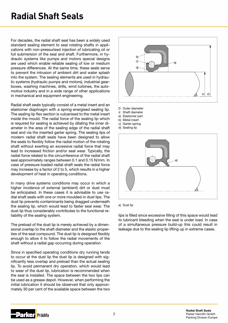
Due to the geometry of the sealing lip and the position of the spring effect line an asymmetric distribution of com-pression occurs in the contact area on the shaft with a steep gradient towards the pressure side. In addition to the sealing lip geometry, this distribution of compression has a crucial influence on the dynamic sealing capability of a radial shaft seal.
a)
b
d h11
Sliding surface
Functional Principle
Radial shaft seals ensure dynamic and static sealing at the shaft by means of a specially shaped sealing lip, which is assisted by an inserted garter spring. Static sealing is achieved by the radial interference fit in the housing bore.
When the shaft is at rest the radial contact force ensures the sealing effect via the preload of the elastomer sealing lip and the inserted garter spring. When the shaft rotates a mixed-friction condition occurs in which the sealing lip partially lifts off of the shaft and lubricant can migrate into the resulting gap. As a result of micro-structures oc-curring in the contact area of the sealing lip, radial shaft seals have a certain pump-back capacity which ensures that the medium cannot escape in the contact area and can be pumped back into the pressure chamber. At the same time, there is always a sufficient amount of lubricant present in the sealing gap when the shaft rotates, which prevents dry running of the seal. This has a crucial influ-ence on wear of the sealing lip and thus the service life of the sealing element.
Due to the radial preload in the contact area to the shaft the sealing edge is slightly oblate, which results in an axial contact area of an approximate length of 0.2 mm in which the sealing lip continuously bears against the shaft. In case of pressure-loaded shaft seals the contact width increases with rising pressure and may amount to as much as 1.5 mm or higher.
Pressure chamber
Air side
a) Contact areab) Heigth of the radial shaft seal

9Radial Shaft Seals Parker Hannifin GmbHPacking Division Europe
D Outer diameterd Shaft diameterb Heigth of the radial shaft seal
D Outer diameterd Shaft diameterb Heigth of the radial shaft seal
Design and Installation
Press Fit Allowance and Diameter Difference for Outer Diameter D
Radial shaft seals have an interference fit in the housing bore, which ensures static sealing across the entire oper-ating temperature range for all materials used. This even applies to housing materials with higher temperature coef-ficients of expansion such as aluminium. Depending on the type of shaft seal (rubber-covered or without rubber cover on the outer diameter), the diameter-relevant press fit allowances used are specified in applicable standards (e.g. DIN 3760/DIN 3791, Part 1 or ISO 6194, Part 1). For shaft seals with grooved outer contours on the outer di-ameter, a slightly larger press fit allowance has generally been selected.
Seal Outer Diameter Tolerance for Shaft Seals without Rubber Cover
Seal Outer Diameter Tolerance for Rubber-covered Shaft Seals
Outer Ø D (mm) Press fit allowance 1) (mm)
Roundness tolerance 2) (mm)> ≤
50 +0.30+0.15 0.25
50 80 +0.35+0.20 0.35
80 120 +0.35+0.20 0.50
120 180 +0.45+0.25 0.60
180 300 +0.45+0.25 0.80
300 500 +0.55+0.30 1.00
1) The total of the actual dimensions of D divided by the total of the measure-ments must be within the dimension of D + press fit allowance. For seals
with a grooved surface, other press fit allowances are required and should be agreed between the manufacturer and the user.2) The diameter difference (Dmax – Dmin) is obtained by three or more measure-
ments which are evenly distributed on the circumference.
Outer Ø D (mm) Press fitallowance 1) (mm)
Roundness tolerance 2) (mm)> ≤
50 +0.20+0.08 0.18
50 80 +0.23+0.09 0.25
80 120 +0.25+0.10 0.30
120 180 +0.28+0.12 0.40
180 300 +0.35+0.15 0.0025 x D
300 500 +0.45+0.20 0.0025 x D
1) The total of the actual dimensions of D divided by the total of the measure-ments must be within the dimension of D + press fit allowance. For seals with a grooved surface, other press fit allowances are required and should be agreed between the manufacturer and the user.
2) The diameter difference (Dmax – Dmin) is obtained by three or more measure-ments which are evenly distributed on the circumference.
d
D
b
d
D
b
Radial Shaft Seals
10Radial Shaft Seals Parker Hannifin GmbHPacking Division Europe
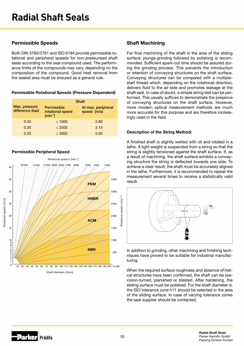
Permissible Rotational Speeds (Pressure-Dependent)
Permissible Speeds
Both DIN 3760/3761 and ISO 6194 provide permissible ro-tational and peripheral speeds for non-pressurised shaft seals according to the seal compound used. The perform-ance limits of the compounds may vary, depending on the composition of the compound. Good heat removal from the sealed area must be ensured as a general rule.
Max. pressure difference (bar)
Shaft
Permissible rotational speed(min-1)
At max. peripheral speed (m/s)
0.50 ≤ 1000 2.80
0.35 ≤ 2000 3.15
0.20 ≤ 3000 5.60
Shaft Machining For final machining of the shaft in the area of the sliding surface, plunge-grinding followed by polishing is recom-mended. Sufficient spark-out time should be assured dur-ing the grinding process. This prevents the introduction or retention of conveying structures on the shaft surface. Conveying structures can be compared with a multiple-start thread which, depending on the rotational direction, delivers fluid to the air side and promotes leakage at the shaft seal. In case of doubt, a simple string test can be per-formed. This usually suffices to demonstrate the presence of conveying structures on the shaft surface. However, more modern optical measurement methods are much more accurate for this purpose and are therefore increas-ingly used in the field.
Permissible Peripheral Speed
Description of the String Method:
A finished shaft is slightly wetted with oil and rotated in a lathe. A light weight is suspended from a string so that the string is slightly tensioned against the shaft surface. If, as a result of machining, the shaft surface exhibits a convey-ing structure the string is deflected towards one side. To achieve a clear result, the shaft must be accurately aligned in the lathe. Furthermore, it is recommended to repeat the measurement several times to receive a statistically valid result.
In addition to grinding, other machining and finishing tech-niques have proved to be suitable for industrial manufac-turing.
When the required surface roughness and absence of heli-cal structures have been confirmed, the shaft can be pre-cision-turned, planished or blasted. After hardening, the sliding surface must be polished. For the shaft diameter d, the ISO tolerance zone h11 should be selected in the area of the sliding surface. In case of varying tolerance zones the seal supplier should be contacted.
0123456789
10
15
20
25
30
35
4030 000 15 000 10 000 9 000 8 000 7 000 6 000 5 000 4 500 4 000
500
1 000
1 500
2 000
2 500
3 000
3 500
10 20 30 40 50 60 70 80 90 100 110 120 130 140 150 160 170 180 190 200 to 500
Per
iphe
ral s
pee
d v
[m/s
]
Shaft diameter d [mm]
Rotational speed n [min-1]
Ro
tatio
nal s
pee
d n
[min
-1]
FKM
HNBR
ACM
NBR
Radial Shaft Seals
11Radial Shaft Seals Parker Hannifin GmbHPacking Division Europe
Hardness of the Mating Surface
In the area of the mating surface of the radial shaft seal a minimum surface hardness of 45 HRC with a hardening depth of at least 0.3 mm is recommended. For peripheral speeds of more than 4 m/s, heavy dirt and/or pressures between 0.5 and 5 bar, a hardness of at least 55 HRC is recommended, in case of higher pressures shaft hardness should range between 60 and 65 HRC.
Surface Roughness of the Shaft For standard radial shaft seals according to DIN 3760/DIN3761:• Ra 0.2 to 0.6 µm • Rz 1.0 to 4.0 µm • Rmax. < 6.3 µm
For pressure-loaded shaft seals:• Ra 0.2 to 0.4 µm • Rz 1.0 to 2.5 µm • Rmax. < 4 µm
Surface Roughness in the Housing • Ra 1.6 to 4 µm • Rz 6.3 to 16 µm • Rmax. < 25 µm
For the bore diameter D the ISO tolerance zone H8 should be selected. In case of varying tolerance zones the seal supplier should be contacted.
Installation
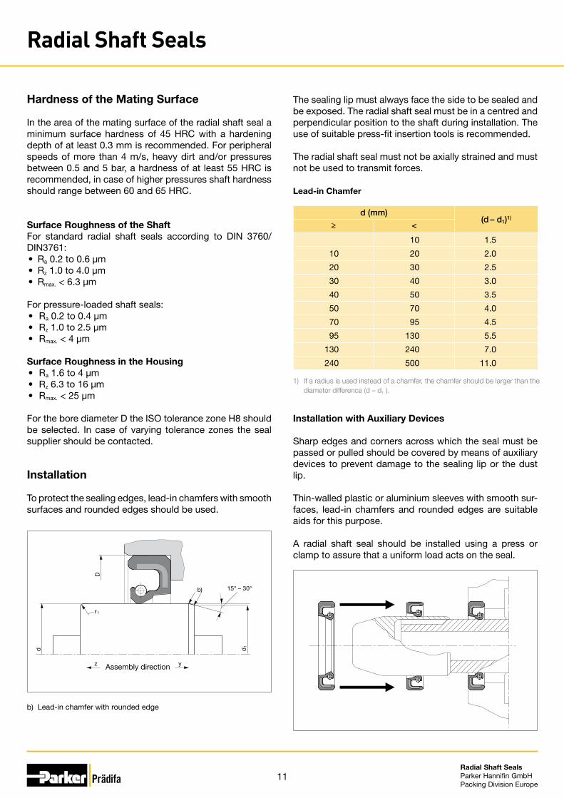
To protect the sealing edges, lead-in chamfers with smooth surfaces and rounded edges should be used.
The sealing lip must always face the side to be sealed and be exposed. The radial shaft seal must be in a centred and perpendicular position to the shaft during installation. The use of suitable press-fit insertion tools is recommended.
The radial shaft seal must not be axially strained and must not be used to transmit forces.
b)
r1
yz
D
15° – 30°
Assembly direction
d d1
d (mm)(d – d1)1)
≥ <
10 1.5
10 20 2.0
20 30 2.5
30 40 3.0
40 50 3.5
50 70 4.0
70 95 4.5
95 130 5.5
130 240 7.0
240 500 11.0
1) If a radius is used instead of a chamfer, the chamfer should be larger than the diameter difference (d – d1 ).
Installation with Auxiliary Devices
Sharp edges and corners across which the seal must be passed or pulled should be covered by means of auxiliary devices to prevent damage to the sealing lip or the dust lip.
Thin-walled plastic or aluminium sleeves with smooth sur-faces, lead-in chamfers and rounded edges are suitable aids for this purpose.
A radial shaft seal should be installed using a press or clamp to assure that a uniform load acts on the seal.
Lead-in Chamfer
b) Lead-in chamfer with rounded edge
Radial Shaft Seals
12Radial Shaft Seals Parker Hannifin GmbHPacking Division Europe
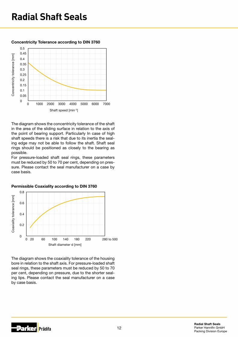
The diagram shows the concentricity tolerance of the shaft in the area of the sliding surface in relation to the axis of the point of bearing support. Particularly In case of high shaft speeds there is a risk that due to its inertia the seal-ing edge may not be able to follow the shaft. Shaft seal rings should be positioned as closely to the bearing as possible. For pressure-loaded shaft seal rings, these parameters must be reduced by 50 to 70 per cent, depending on pres-sure. Please contact the seal manufacturer on a case by case basis.
Concentricity Tolerance according to DIN 3760
Permissible Coaxiality according to DIN 3760
The diagram shows the coaxiality tolerance of the housing bore in relation to the shaft axis. For pressure-loaded shaft seal rings, these parameters must be reduced by 50 to 70 per cent, depending on pressure, due to the shorter seal-ing lips. Please contact the seal manufacturer on a case by case basis.
Shaft speed [min-1]
Co
ncen
tric
ity t
ole
ranc
e [m
m]
0
0.05
0.1
0.15
0.2
0.25
0.3
0.35
0.4
0.5
0.45
10000 2000 3000 4000 5000 6000 7000
Co
axia
lity
tole
ranc
e [m
m]
Shaft diameter d [mm]
0
0.2
0.4
0.6
0.8
200 60 100 140 180 220 280 to 500
Radial Shaft Seals
13Radial Shaft Seals Parker Hannifin GmbHPacking Division Europe
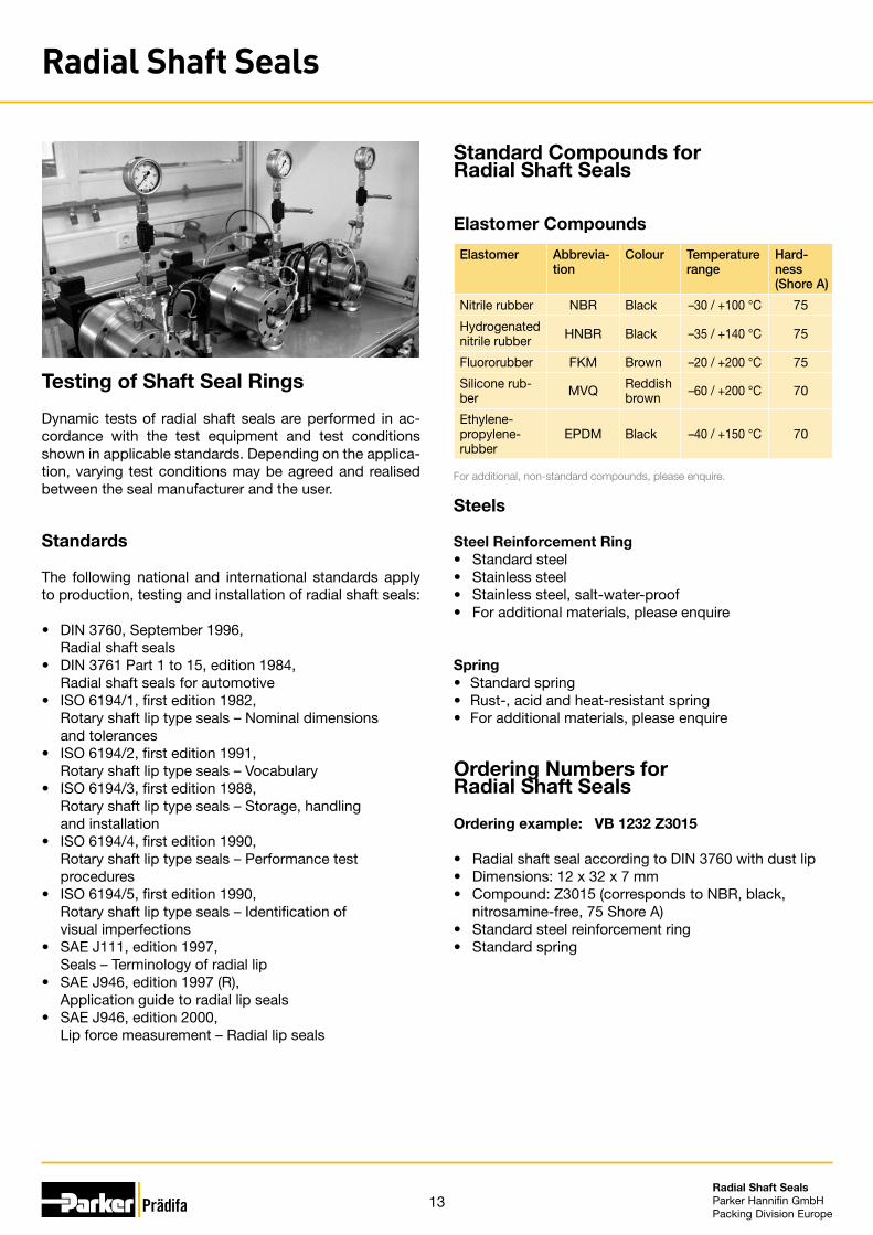
Testing of Shaft Seal Rings
Dynamic tests of radial shaft seals are performed in ac-cordance with the test equipment and test conditions shown in applicable standards. Depending on the applica-tion, varying test conditions may be agreed and realised between the seal manufacturer and the user.
Standards
The following national and international standards apply to production, testing and installation of radial shaft seals:
• DIN 3760, September 1996, Radial shaft seals• DIN 3761 Part 1 to 15, edition 1984, Radial shaft seals for automotive• ISO 6194/1, first edition 1982, Rotary shaft lip type seals – Nominal dimensions and tolerances• ISO 6194/2, first edition 1991, Rotary shaft lip type seals – Vocabulary • ISO 6194/3, first edition 1988, Rotary shaft lip type seals – Storage, handling and installation• ISO 6194/4, first edition 1990, Rotary shaft lip type seals – Performance test procedures• ISO 6194/5, first edition 1990, Rotary shaft lip type seals – Identification of visual imperfections• SAE J111, edition 1997, Seals – Terminology of radial lip• SAE J946, edition 1997 (R), Application guide to radial lip seals• SAE J946, edition 2000, Lip force measurement – Radial lip seals
Standard Compounds for Radial Shaft Seals
Elastomer Abbrevia-tion
Colour Temperature range
Hard-ness(Shore A)
Nitrile rubber NBR Black –30 / +100 °C 75
Hydrogenated nitrile rubber HNBR Black –35 / +140 °C 75
Fluororubber FKM Brown –20 / +200 °C 75
Silicone rub-ber MVQ Reddish
brown –60 / +200 °C 70
Ethylene-propylene- rubber
EPDM Black –40 / +150 °C 70
For additional, non-standard compounds, please enquire.
Steels
Steel Reinforcement Ring• Standard steel• Stainless steel • Stainless steel, salt-water-proof • For additional materials, please enquire
Spring • Standard spring • Rust-, acid and heat-resistant spring • For additional materials, please enquire
Ordering Numbers for Radial Shaft Seals
Ordering example: VB 1232 Z3015
• Radial shaft seal according to DIN 3760 with dust lip • Dimensions: 12 x 32 x 7 mm • Compound: Z3015 (corresponds to NBR, black,
nitrosamine-free, 75 Shore A) • Standard steel reinforcement ring • Standard spring
Elastomer Compounds
Radial Shaft Seals

14Radial Shaft Seals Parker Hannifin GmbHPacking Division Europe
• Design for grooves according to DIN 3760 / 3761 or ISO 6194.• Lip ring with spiral spring for radial preloading.• Interference fit on outer diameter.• Cut sealing edge for high dynamic sealing effect.• Elastomeric outer case for high static sealing effect.• Easy installation.
Range of applicationPrimarily for sealing oil- and grease-lubricated shaft ducts with very little or no exposure to external (ambient) dirt.
Operating pressure ≤ 0.5 barOperating temperature NBR -30 to +100 °C HNBR -30 to +140 °C FKM -20 to +180 °CSliding speed NBR ≤ 12 m/s HNBR ≤ 25 m/s FKM ≤ 40 m/sMedia Mineral oil based hydraulic oils, PAO, synthetic esters
CompoundsStandard: Z3015, NBR compound, nitrosamine-free (≈ 75 Shore A)For higher requirements: Z3011, HNBR compound (≈ 75 Shore A) Z3000, FKM compound (≈ 75 Shore A)
InstallationThe axial groove depth should correspond to the specifications in DIN 3760/3761 and ISO 6194. To avoid damage to the sealing edge, the seals should not be pulled over sharp edges during installation.Installation as recommended in the above standards is the prerequisite for proper performance of the seal.
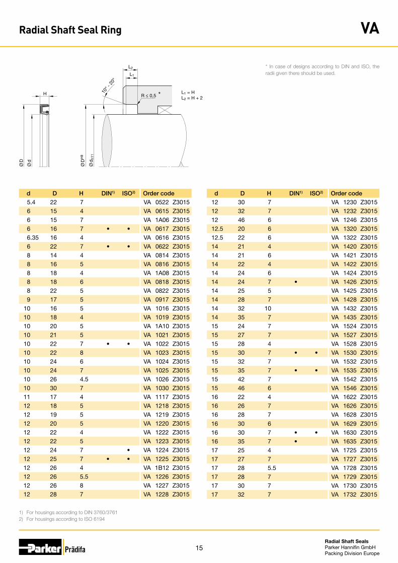
Radial Shaft Seal Ring VA
In case of special operating conditions (specific pressure loads, temperature, speed, use in water, HFA, HFB fluids etc.), please contact our consultancy service for a selection of the material and design best suiting your particular application requirements.
15Radial Shaft Seals Parker Hannifin GmbHPacking Division Europe
L1
L2
L1 = HL2 = H + 2
H 10° -
20°
R ≤ 0,5
Ø D
H8
Ø d
h11
Ø D
Ø d
1) For housings according to DIN 3760/37612) For housings according to ISO 6194
*
d D H DIN1) ISO2) Order code
12 30 7 VA 1230 Z3015
12 32 7 VA 1232 Z3015
12 46 6 VA 1246 Z3015
12.5 20 6 VA 1320 Z3015
12.5 22 6 VA 1322 Z3015
14 21 4 VA 1420 Z3015
14 21 6 VA 1421 Z3015
14 22 4 VA 1422 Z3015
14 24 6 VA 1424 Z3015
14 24 7 • VA 1426 Z3015
14 25 5 VA 1425 Z3015
14 28 7 VA 1428 Z3015
14 32 10 VA 1432 Z3015
14 35 7 VA 1435 Z3015
15 24 7 VA 1524 Z3015
15 27 7 VA 1527 Z3015
15 28 4 VA 1528 Z3015
15 30 7 • • VA 1530 Z3015
15 32 7 VA 1532 Z3015
15 35 7 • • VA 1535 Z3015
15 42 7 VA 1542 Z3015
15 46 6 VA 1546 Z3015
16 22 4 VA 1622 Z3015
16 26 7 VA 1626 Z3015
16 28 7 VA 1628 Z3015
16 30 6 VA 1629 Z3015
16 30 7 • • VA 1630 Z3015
16 35 7 • VA 1635 Z3015
17 25 4 VA 1725 Z3015
17 27 7 VA 1727 Z3015
17 28 5.5 VA 1728 Z3015
17 28 7 VA 1729 Z3015
17 30 7 VA 1730 Z3015
17 32 7 VA 1732 Z3015
d D H DIN1) ISO2) Order code
5.4 22 7 VA 0522 Z3015
6 15 4 VA 0615 Z3015
6 15 7 VA 1A06 Z3015
6 16 7 • • VA 0617 Z3015
6.35 16 4 VA 0616 Z3015
6 22 7 • • VA 0622 Z3015
8 14 4 VA 0814 Z3015
8 16 5 VA 0816 Z3015
8 18 4 VA 1A08 Z3015
8 18 6 VA 0818 Z3015
8 22 5 VA 0822 Z3015
9 17 5 VA 0917 Z3015
10 16 5 VA 1016 Z3015
10 18 4 VA 1019 Z3015
10 20 5 VA 1A10 Z3015
10 21 5 VA 1021 Z3015
10 22 7 • • VA 1022 Z3015
10 22 8 VA 1023 Z3015
10 24 6 VA 1024 Z3015
10 24 7 VA 1025 Z3015
10 26 4.5 VA 1026 Z3015
10 30 7 VA 1030 Z3015
11 17 4 VA 1117 Z3015
12 18 5 VA 1218 Z3015
12 19 5 VA 1219 Z3015
12 20 5 VA 1220 Z3015
12 22 4 VA 1222 Z3015
12 22 5 VA 1223 Z3015
12 24 7 • VA 1224 Z3015
12 25 7 • • VA 1225 Z3015
12 26 4 VA 1B12 Z3015
12 26 5.5 VA 1226 Z3015
12 26 8 VA 1227 Z3015
12 28 7 VA 1228 Z3015
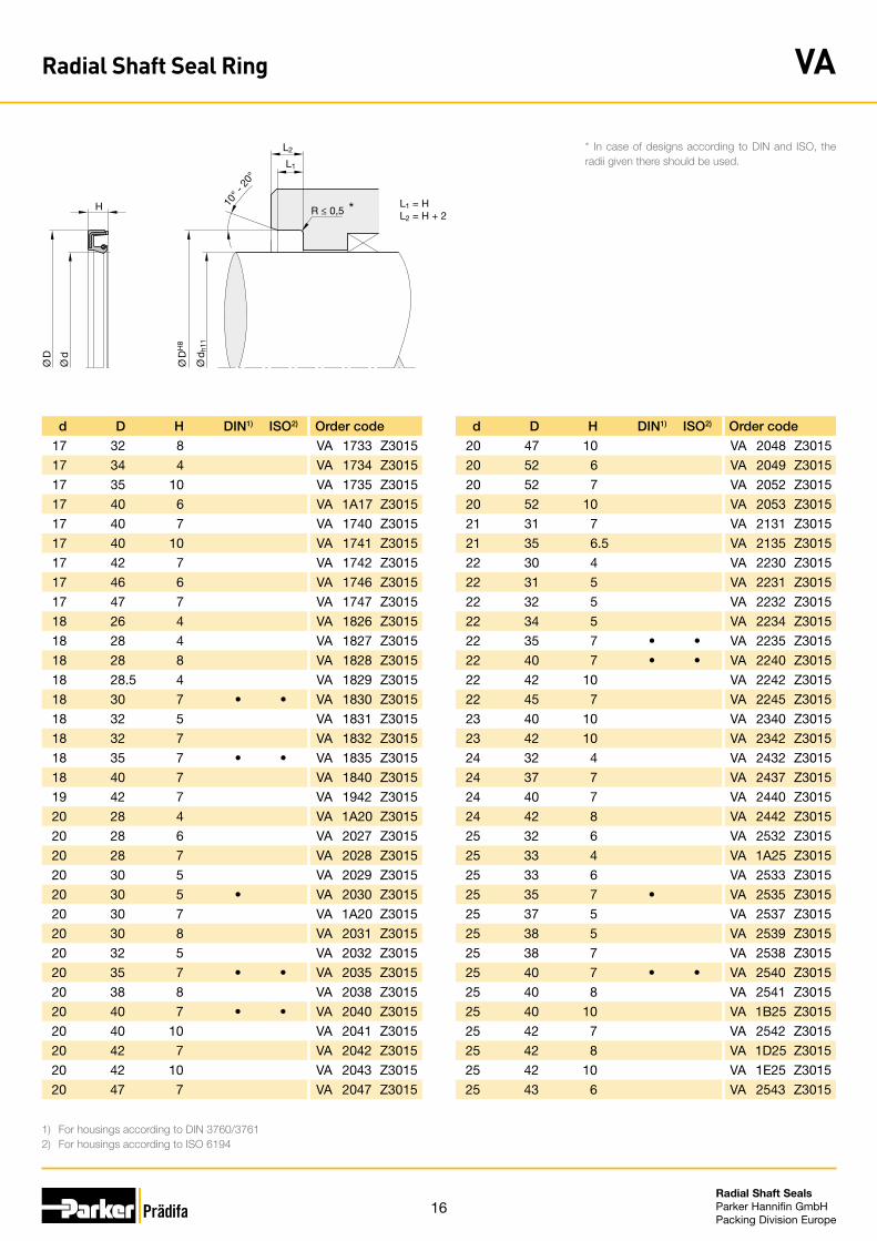
Radial Shaft Seal Ring VA
* In case of designs according to DIN and ISO, the radii given there should be used.
16Radial Shaft Seals Parker Hannifin GmbHPacking Division Europe
d D H DIN1) ISO2) Order code
17 32 8 VA 1733 Z3015
17 34 4 VA 1734 Z3015
17 35 10 VA 1735 Z3015
17 40 6 VA 1A17 Z3015
17 40 7 VA 1740 Z3015
17 40 10 VA 1741 Z3015
17 42 7 VA 1742 Z3015
17 46 6 VA 1746 Z3015
17 47 7 VA 1747 Z3015
18 26 4 VA 1826 Z3015
18 28 4 VA 1827 Z3015
18 28 8 VA 1828 Z3015
18 28.5 4 VA 1829 Z3015
18 30 7 • • VA 1830 Z3015
18 32 5 VA 1831 Z3015
18 32 7 VA 1832 Z3015
18 35 7 • • VA 1835 Z3015
18 40 7 VA 1840 Z3015
19 42 7 VA 1942 Z3015
20 28 4 VA 1A20 Z3015
20 28 6 VA 2027 Z3015
20 28 7 VA 2028 Z3015
20 30 5 VA 2029 Z3015
20 30 5 • VA 2030 Z3015
20 30 7 VA 1A20 Z3015
20 30 8 VA 2031 Z3015
20 32 5 VA 2032 Z3015
20 35 7 • • VA 2035 Z3015
20 38 8 VA 2038 Z3015
20 40 7 • • VA 2040 Z3015
20 40 10 VA 2041 Z3015
20 42 7 VA 2042 Z3015
20 42 10 VA 2043 Z3015
20 47 7 VA 2047 Z3015
d D H DIN1) ISO2) Order code
20 47 10 VA 2048 Z3015
20 52 6 VA 2049 Z3015
20 52 7 VA 2052 Z3015
20 52 10 VA 2053 Z3015
21 31 7 VA 2131 Z3015
21 35 6.5 VA 2135 Z3015
22 30 4 VA 2230 Z3015
22 31 5 VA 2231 Z3015
22 32 5 VA 2232 Z3015
22 34 5 VA 2234 Z3015
22 35 7 • • VA 2235 Z3015
22 40 7 • • VA 2240 Z3015
22 42 10 VA 2242 Z3015
22 45 7 VA 2245 Z3015
23 40 10 VA 2340 Z3015
23 42 10 VA 2342 Z3015
24 32 4 VA 2432 Z3015
24 37 7 VA 2437 Z3015
24 40 7 VA 2440 Z3015
24 42 8 VA 2442 Z3015
25 32 6 VA 2532 Z3015
25 33 4 VA 1A25 Z3015
25 33 6 VA 2533 Z3015
25 35 7 • VA 2535 Z3015
25 37 5 VA 2537 Z3015
25 38 5 VA 2539 Z3015
25 38 7 VA 2538 Z3015
25 40 7 • • VA 2540 Z3015
25 40 8 VA 2541 Z3015
25 40 10 VA 1B25 Z3015
25 42 7 VA 2542 Z3015
25 42 8 VA 1D25 Z3015
25 42 10 VA 1E25 Z3015
25 43 6 VA 2543 Z3015
*
1) For housings according to DIN 3760/37612) For housings according to ISO 6194
L1
L2
L1 = HL2 = H + 2
H 10° -
20°
R ≤ 0,5
Ø D
H8
Ø d
h11
Ø D
Ø d
*
* In case of designs according to DIN and ISO, the radii given there should be used.
Radial Shaft Seal Ring VA

17Radial Shaft Seals Parker Hannifin GmbHPacking Division Europe
d D H DIN1) ISO2) Order code
25 43 9 VA 2544 Z3015
25 47 7 • • VA 2547 Z3015
25 47 10 VA 2548 Z3015
25 52 7 • • VA 2552 Z3015
25 52 10 VA 2553 Z3015
25 62 6 VA 2562 Z3015
25 62 10 VA 2563 Z3015
25.4 41 6 VA 2641 Z3015
26 36 7 VA 2636 Z3015
26 38 8 VA 2638 Z3015
27 40 7 VA 2740 Z3015
27 47 7 VA 2747 Z3015
27 49 7.5 VA 2749 Z3015
28 38 7 VA 2838 Z3015
28 40 7 • • VA 2840 Z3015
28 43 10 VA 2843 Z3015
28 47 7 • • VA 2847 Z3015
28 52 7 • • VA 2852 Z3015
29 38 5 VA 2037 Z3015
29 38 7 VA 2938 Z3015
29 40 7 VA 2940 Z3015
29 43 7 VA 2943 Z3015
29 62 10 VA 2962 Z3015
30 38 4 VA 3038 Z3015
30 40 7 • VA 3040 Z3015
30 42 8 VA 3042 Z3015
30 43 8 VA 3043 Z3015
30 45 8 VA 3045 Z3015
30 47 7 • • VA 3047 Z3015
30 47 10 VA 3048 Z3015
30 50 7 VA 3050 Z3015
30 50 10 VA 3051 Z3015
30 52 7 • • VA 3052 Z3015
30 52 8 VA 3053 Z3015
d D H DIN1) ISO2) Order code
30 52 10 VA 1B30 Z3015
30 54 10 VA 3054 Z3015
30 55 7 VA 3055 Z3015
30 62 7 VA 3062 Z3015
30 62 10 VA 3063 Z3015
30 68 10 VA 3068 Z3015
30 72 6 VA 3072 Z3015
30 72 10 VA 3073 Z3015
32 42 5 VA 3241 Z3015
32 42 7 VA 3242 Z3015
32 43 6 VA 3243 Z3015
32 44 10 VA 3244 Z3015
32 45 7 • VA 3245 Z3015
32 45 10 VA 3246 Z3015
32 50 7 VA 3250 Z3015
32 50 8 VA 3251 Z3015
32 52 7 • VA 3252 Z3015
32 52 10 VA 3253 Z3015
34 46 8 VA 3446 Z3015
34 47 9 VA 3447 Z3015
34 50 10 VA 3450 Z3015
34 52 8 VA 3452 Z3015
34 57 6 VA 3457 Z3015
34 62 10 VA 3462 Z3015
35 45 7 VA 3545 Z3015
35 47 7 VA 3547 Z3015
35 50 7 • VA 3550 Z3015
35 50 8 • • VA 3551 Z3015
35 50 10 VA 1B35 Z3015
35 52 7 • VA 3552 Z3015
35 52 8 • • VA 3553 Z3015
35 55 7 • VA 3555 Z3015
35 55 8 • • VA 3556 Z3015
35 62 7 VA 3562 Z3015
*
1) For housings according to DIN 3760/37612) For housings according to ISO 6194
L1
L2
L1 = HL2 = H + 2
H 10° -
20°
R ≤ 0,5
Ø D
H8
Ø d
h11
Ø D
Ø d
*
* In case of designs according to DIN and ISO, the radii given there should be used.
Radial Shaft Seal Ring VA

18Radial Shaft Seals Parker Hannifin GmbHPacking Division Europe
1) For housings according to DIN 3760/37612) For housings according to ISO 6194
d D H DIN1) ISO2) Order code
35 62 10 VA 3563 Z3015
35 65 10 VA 3565 Z3015
35 72 10 VA 3572 Z3015
35 80 13 VA 3580 Z3015
35 82 6 VA 3582 Z3015
36 45 7 VA 3645 Z3015
36 54 7.5 VA 3654 Z3015
37 62 10 VA 3762 Z3015
38 48 7 VA 3848 Z3015
38 50 7 VA 3850 Z3015
38 52 10 VA 3852 Z3015
38 53 8 VA 3853 Z3015
38 62 7 • VA 3862 Z3015
38 80 10 VA 3880 Z3015
40 50 7 VA 4050 Z3015
40 50 8 VA 4051 Z3015
40 52 6 VA 1A40 Z3015
40 52 7 • VA 4052 Z3015
40 55 6.5 VA 4054 Z3015
40 55 8 • • VA 1B40 Z3015
40 55 10 VA 4055 Z3015
40 58 7 VA 4058 Z3015
40 60 8 VA 4060 Z3015
40 60 10 VA 4061 Z3015
40 62 7 • VA 4062 Z3015
40 62 10 VA 4063 Z3015
40 65 10 VA 4065 Z3015
40 68 12 VA 4068 Z3015
40 72 7 VA 4072 Z3015
40 80 10 VA 4080 Z3015
40 88 6 VA 4088 Z3015
40 90 12 VA 4090 Z3015
42 52 4 VA 4252 Z3015
42 55 7 VA 4255 Z3015
d D H DIN1) ISO2) Order code
42 55 8 • • VA 4256 Z3015
42 62 8 • • VA 4262 Z3015
42 62 10 VA 4263 Z3015
42 64 7 VA 4264 Z3015
42 72 8 VA 4272 Z3015
42 72 10 VA 4273 Z3015
43 60 10 VA 4360 Z3015
45 55 7 VA 4555 Z3015
45 58 7 VA 4558 Z3015
45 59 10 VA 4559 Z3015
45 60 7 VA 4560 Z3015
45 60 8 • VA 4561 Z3015
45 60 10 VA 1A45 Z3015
45 62 7 VA 4562 Z3015
45 62 8 • • VA 4563 Z3015
45 65 8 • • VA 4565 Z3015
45 65 10 VA 4566 Z3015
45 72 8 VA 4572 Z3015
45 80 8 VA 4580 Z3015
45 80 10 VA 4581 Z3015
46 72 10 VA 4672 Z3015
46.2 80 10 VA 4680 Z3015
47 62 7 VA 4762 Z3015
48 60 10 VA 4860 Z3015
48 61 10 VA 4861 Z3015
48 62 8 • VA 4862 Z3015
48 65 10 VA 4865 Z3015
48 72 8 VA 4872 Z3015
48 72.5 10 VA 4873 Z3015
48 90 10 VA 4890 Z3015
50 60 7 VA 5060 Z3015
50 62 6 VA 5062 Z3015
50 65 7 VA 5065 Z3015
50 65 8 • VA 5066 Z3015
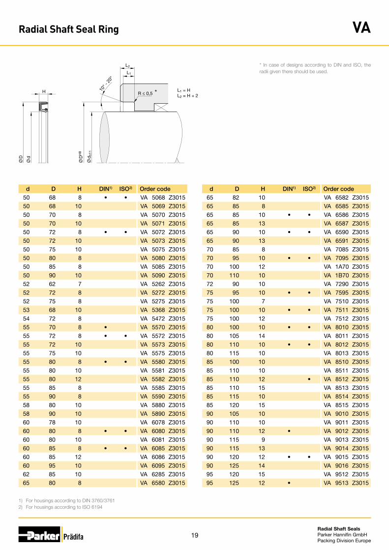
*
1) For housings according to DIN 3760/37612) For housings according to ISO 6194
L1
L2
L1 = HL2 = H + 2
H 10° -
20°
R ≤ 0,5
Ø D
H8
Ø d
h11
Ø D
Ø d
*
* In case of designs according to DIN and ISO, the radii given there should be used.
Radial Shaft Seal Ring VA
19Radial Shaft Seals Parker Hannifin GmbHPacking Division Europe
d D H DIN1) ISO2) Order code
50 68 8 • • VA 5068 Z3015
50 68 10 VA 5069 Z3015
50 70 8 VA 5070 Z3015
50 70 10 VA 5071 Z3015
50 72 8 • • VA 5072 Z3015
50 72 10 VA 5073 Z3015
50 75 10 VA 5075 Z3015
50 80 8 VA 5080 Z3015
50 85 8 VA 5085 Z3015
50 90 10 VA 5090 Z3015
52 62 7 VA 5262 Z3015
52 72 8 VA 5272 Z3015
52 75 8 VA 5275 Z3015
53 68 10 VA 5368 Z3015
54 72 8 VA 5472 Z3015
55 70 8 • VA 5570 Z3015
55 72 8 • • VA 5572 Z3015
55 72 10 VA 5573 Z3015
55 75 10 VA 5575 Z3015
55 80 8 • • VA 5580 Z3015
55 80 10 VA 5581 Z3015
55 80 12 VA 5582 Z3015
55 85 8 VA 5585 Z3015
55 90 8 VA 5590 Z3015
58 80 10 VA 5880 Z3015
58 90 10 VA 5890 Z3015
60 78 10 VA 6078 Z3015
60 80 8 • • VA 6080 Z3015
60 80 10 VA 6081 Z3015
60 85 8 • • VA 6085 Z3015
60 85 12 VA 6086 Z3015
60 95 10 VA 6095 Z3015
62 85 10 VA 6285 Z3015
65 80 8 VA 6580 Z3015
d D H DIN1) ISO2) Order code
65 82 10 VA 6582 Z3015
65 85 8 VA 6585 Z3015
65 85 10 • • VA 6586 Z3015
65 85 13 VA 6587 Z3015
65 90 10 • • VA 6590 Z3015
65 90 13 VA 6591 Z3015
70 85 8 VA 7085 Z3015
70 95 10 • • VA 7095 Z3015
70 100 12 VA 1A70 Z3015
70 110 10 VA 1B70 Z3015
72 90 10 VA 7290 Z3015
75 95 10 • • VA 7595 Z3015
75 100 7 VA 7510 Z3015
75 100 10 • • VA 7511 Z3015
75 100 12 VA 7512 Z3015
80 100 10 • • VA 8010 Z3015
80 105 14 VA 8011 Z3015
80 110 10 • • VA 8012 Z3015
80 115 10 VA 8013 Z3015
85 100 10 VA 8510 Z3015
85 110 10 VA 8511 Z3015
85 110 12 • VA 8512 Z3015
85 110 15 VA 8513 Z3015
85 115 10 VA 8514 Z3015
85 120 15 VA 8515 Z3015
90 105 10 VA 9010 Z3015
90 110 10 VA 9011 Z3015
90 110 12 • VA 9012 Z3015
90 115 9 VA 9013 Z3015
90 115 13 VA 9014 Z3015
90 120 12 • • VA 9015 Z3015
90 125 14 VA 9016 Z3015
95 120 15 VA 9512 Z3015
95 125 12 • VA 9513 Z3015
*
1) For housings according to DIN 3760/37612) For housings according to ISO 6194
L1
L2
L1 = HL2 = H + 2
H 10° -
20°
R ≤ 0,5
Ø D
H8
Ø d
h11
Ø D
Ø d
*
* In case of designs according to DIN and ISO, the radii given there should be used.
Radial Shaft Seal Ring VA
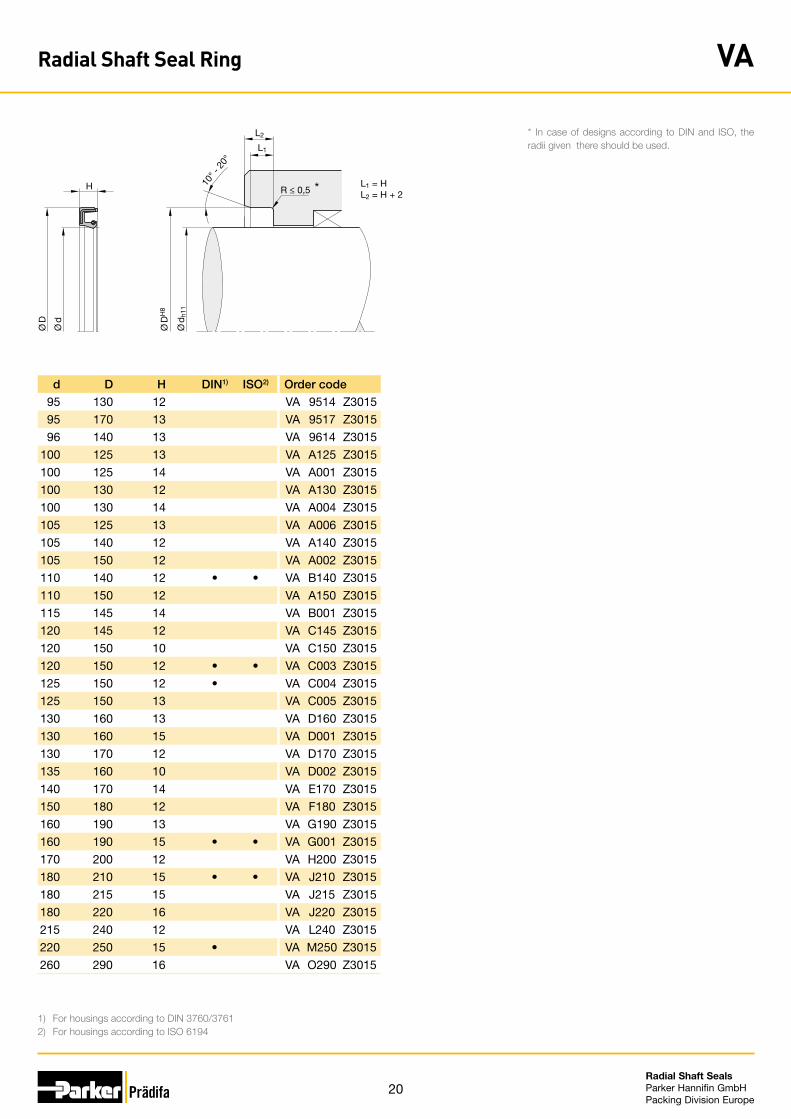
20Radial Shaft Seals Parker Hannifin GmbHPacking Division Europe
d D H DIN1) ISO2) Order code
95 130 12 VA 9514 Z3015
95 170 13 VA 9517 Z3015
96 140 13 VA 9614 Z3015
100 125 13 VA A125 Z3015
100 125 14 VA A001 Z3015
100 130 12 VA A130 Z3015
100 130 14 VA A004 Z3015
105 125 13 VA A006 Z3015
105 140 12 VA A140 Z3015
105 150 12 VA A002 Z3015
110 140 12 • • VA B140 Z3015
110 150 12 VA A150 Z3015
115 145 14 VA B001 Z3015
120 145 12 VA C145 Z3015
120 150 10 VA C150 Z3015
120 150 12 • • VA C003 Z3015
125 150 12 • VA C004 Z3015
125 150 13 VA C005 Z3015
130 160 13 VA D160 Z3015
130 160 15 VA D001 Z3015
130 170 12 VA D170 Z3015
135 160 10 VA D002 Z3015
140 170 14 VA E170 Z3015
150 180 12 VA F180 Z3015
160 190 13 VA G190 Z3015
160 190 15 • • VA G001 Z3015
170 200 12 VA H200 Z3015
180 210 15 • • VA J210 Z3015
180 215 15 VA J215 Z3015
180 220 16 VA J220 Z3015
215 240 12 VA L240 Z3015
220 250 15 • VA M250 Z3015
260 290 16 VA O290 Z3015
*
1) For housings according to DIN 3760/37612) For housings according to ISO 6194
L1
L2
L1 = HL2 = H + 2
H 10° -
20°
R ≤ 0,5
Ø D
H8
Ø d
h11
Ø D
Ø d
*
* In case of designs according to DIN and ISO, the radii given there should be used.
Radial Shaft Seal Ring VA
21Radial Shaft Seals Parker Hannifin GmbHPacking Division Europe
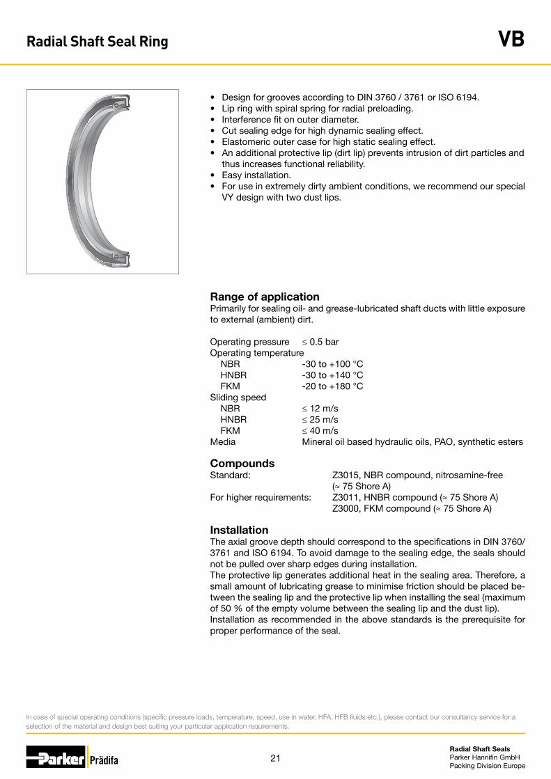
• Design for grooves according to DIN 3760 / 3761 or ISO 6194.• Lip ring with spiral spring for radial preloading.• Interference fit on outer diameter.• Cut sealing edge for high dynamic sealing effect.• Elastomeric outer case for high static sealing effect.• An additional protective lip (dirt lip) prevents intrusion of dirt particles and
thus increases functional reliability. • Easy installation.• For use in extremely dirty ambient conditions, we recommend our special
VY design with two dust lips.
Range of applicationPrimarily for sealing oil- and grease-lubricated shaft ducts with little exposure to external (ambient) dirt.
Operating pressure ≤ 0.5 barOperating temperature NBR -30 to +100 °C HNBR -30 to +140 °C FKM -20 to +180 °CSliding speed NBR ≤ 12 m/s HNBR ≤ 25 m/s FKM ≤ 40 m/sMedia Mineral oil based hydraulic oils, PAO, synthetic esters
CompoundsStandard: Z3015, NBR compound, nitrosamine-free (≈ 75 Shore A)For higher requirements: Z3011, HNBR compound (≈ 75 Shore A) Z3000, FKM compound (≈ 75 Shore A)
InstallationThe axial groove depth should correspond to the specifications in DIN 3760/3761 and ISO 6194. To avoid damage to the sealing edge, the seals should not be pulled over sharp edges during installation.The protective lip generates additional heat in the sealing area. Therefore, a small amount of lubricating grease to minimise friction should be placed be-tween the sealing lip and the protective lip when installing the seal (maximum of 50 % of the empty volume between the sealing lip and the dust lip). Installation as recommended in the above standards is the prerequisite for proper performance of the seal.
In case of special operating conditions (specific pressure loads, temperature, speed, use in water, HFA, HFB fluids etc.), please contact our consultancy service for a selection of the material and design best suiting your particular application requirements.
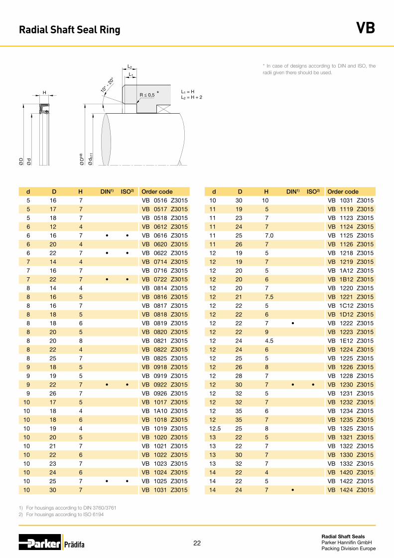
Radial Shaft Seal Ring VB
22Radial Shaft Seals Parker Hannifin GmbHPacking Division Europe
d D H DIN1) ISO2) Order code
10 30 10 VB 1031 Z3015
11 19 5 VB 1119 Z3015
11 23 7 VB 1123 Z3015
11 24 7 VB 1124 Z3015
11 25 7.0 VB 1125 Z3015
11 26 7 VB 1126 Z3015
12 19 5 VB 1218 Z3015
12 19 7 VB 1219 Z3015
12 20 5 VB 1A12 Z3015
12 20 6 VB 1B12 Z3015
12 20 7 VB 1220 Z3015
12 21 7.5 VB 1221 Z3015
12 22 5 VB 1C12 Z3015
12 22 6 VB 1D12 Z3015
12 22 7 • VB 1222 Z3015
12 22 9 VB 1223 Z3015
12 24 4.5 VB 1E12 Z3015
12 24 6 VB 1224 Z3015
12 25 5 VB 1225 Z3015
12 26 8 VB 1226 Z3015
12 28 7 VB 1228 Z3015
12 30 7 • • VB 1230 Z3015
12 32 5 VB 1231 Z3015
12 32 7 VB 1232 Z3015
12 35 6 VB 1234 Z3015
12 35 7 VB 1235 Z3015
12.5 25 8 VB 1325 Z3015
13 22 5 VB 1321 Z3015
13 22 7 VB 1322 Z3015
13 30 7 VB 1330 Z3015
13 32 7 VB 1332 Z3015
14 22 4 VB 1420 Z3015
14 22 5 VB 1422 Z3015
14 24 7 • VB 1424 Z3015
d D H DIN1) ISO2) Order code
5 16 7 VB 0516 Z3015
5 17 7 VB 0517 Z3015
5 18 7 VB 0518 Z3015
6 12 4 VB 0612 Z3015
6 16 7 • • VB 0616 Z3015
6 20 4 VB 0620 Z3015
6 22 7 • • VB 0622 Z3015
7 14 4 VB 0714 Z3015
7 16 7 VB 0716 Z3015
7 22 7 • • VB 0722 Z3015
8 14 4 VB 0814 Z3015
8 16 5 VB 0816 Z3015
8 16 7 VB 0817 Z3015
8 18 5 VB 0818 Z3015
8 18 6 VB 0819 Z3015
8 20 5 VB 0820 Z3015
8 20 8 VB 0821 Z3015
8 22 4 VB 0822 Z3015
8 25 7 VB 0825 Z3015
9 18 5 VB 0918 Z3015
9 19 5 VB 0919 Z3015
9 22 7 • • VB 0922 Z3015
9 26 7 VB 0926 Z3015
10 17 5 VB 1017 Z3015
10 18 4 VB 1A10 Z3015
10 18 6 VB 1018 Z3015
10 19 4 VB 1019 Z3015
10 20 5 VB 1020 Z3015
10 21 7 VB 1021 Z3015
10 22 6 VB 1022 Z3015
10 23 7 VB 1023 Z3015
10 24 6 VB 1024 Z3015
10 25 7 • • VB 1025 Z3015
10 30 7 VB 1031 Z3015
1) For housings according to DIN 3760/37612) For housings according to ISO 6194
L1
L2
H 10° -
20°
R ≤ 0,5
Ø D
H8
Ø d
h11
Ø D
Ø d
L1 = HL2 = H + 2
*
* In case of designs according to DIN and ISO, the radii given there should be used.
Radial Shaft Seal Ring VB

23Radial Shaft Seals Parker Hannifin GmbHPacking Division Europe
d D H DIN1) ISO2) Order code
14 25 7 VB 1425 Z3015
14 26 7 VB 1426 Z3015
14 28 7 VB 1427 Z3015
14 28 8 VB 1428 Z3015
14 29 7 VB 1429 Z3015
14 30 7 • VB 1430 Z3015
14 32 7 VB 1432 Z3015
14 35 7 VB 1435 Z3015
14 35 8 VB 1436 Z3015
15 21 4 VB 1520 Z3015
15 21 5 VB 1521 Z3015
15 22 7 VB 1522 Z3015
15 23 7 VB 1523 Z3015
15 24 7 VB 1524 Z3015
15 25 4 VB 1A15 Z3015
15 25 5 VB 1B15 Z3015
15 25 7 VB 1525 Z3015
15 25 8 VB 1C15 Z3015
15 26 4.5 VB 1D15 Z3015
15 26 5 VB 1E15 Z3015
15 26 7 VB 1526 Z3015
15 26 8 VB 1527 Z3015
15 30 6 VB 1529 Z3015
15 30 7 • • VB 1530 Z3015
15 31 7 VB 1531 Z3015
15 32 5 VB 1F15 Z3015
15 32 9 VB 1532 Z3015
15 32 10 VB 1533 Z3015
15 35 7 • • VB 1535 Z3015
15 35 10 VB 1536 Z3015
15 37 7 VB 1537 Z3015
15 40 10 VB 1540 Z3015
15 47 10 VB 1547 Z3015
16 22 4 VB 1622 Z3015
d D H DIN1) ISO2) Order code
16 24 6.5 VB 1624 Z3015
16 26 7 VB 1626 Z3015
16 26 8 VB 1627 Z3015
16 28 8 VB 1628 Z3015
16 30 7 • • VB 1630 Z3015
16 30 10 VB 1631 Z3015
16 32 7 VB 1632 Z3015
16 32 10 VB 1633 Z3015
16 36 7 VB 1636 Z3015
16 38 7 VB 1638 Z3015
16 40 7 VB 1640 Z3015
16 40 10 VB 1641 Z3015
17 25 4 VB 1724 Z3015
17 25 6 VB 1725 Z3015
17 25.5 7 VB 1A17 Z3015
17 26 6 VB 1B17 Z3015
17 26 7 VB 1726 Z3015
17 27 6 VB 1C17 Z3015
17 27 7 VB 1727 Z3015
17 28 5 VB 1728 Z3015
17 28.5 7 VB 1729 Z3015
17 30 5 VB 1D17 Z3015
17 30 7 VB 1730 Z3015
17 30 8 VB 1731 Z3015
17 32 7 VB 1732 Z3015
17 32 8 VB 1733 Z3015
17 34 7 VB 1734 Z3015
17 35 7 VB 1735 Z3015
17 37 10 VB 1737 Z3015
17 38 7 VB 1738 Z3015
17 40 5 VB 1739 Z3015
17 40 7 VB 1740 Z3015
17 40 10 VB 1741 Z3015
17 42 7 VB 1742 Z3015
1) For housings according to DIN 3760/37612) For housings according to ISO 6194
L1
L2
H 10° -
20°
R ≤ 0,5
Ø D
H8
Ø d
h11
Ø D
Ø d
L1 = HL2 = H + 2
*
* In case of designs according to DIN and ISO, the radii given there should be used.
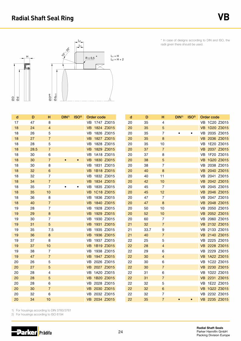
Radial Shaft Seal Ring VB
24Radial Shaft Seals Parker Hannifin GmbHPacking Division Europe
d D H DIN1) ISO2) Order code
17 47 8 VB 1747 Z3015
18 24 4 VB 1824 Z3015
18 26 5 VB 1826 Z3015
18 27 7 VB 1827 Z3015
18 28 5 VB 1828 Z3015
18 28.5 7 VB 1829 Z3015
18 30 6 VB 1A18 Z3015
18 30 7 • • VB 1830 Z3015
18 30 8 VB 1831 Z3015
18 32 6 VB 1B18 Z3015
18 32 7 VB 1832 Z3015
18 34 7 VB 1834 Z3015
18 35 7 • • VB 1835 Z3015
18 35 10 VB 1C18 Z3015
18 36 8 VB 1836 Z3015
18 40 7 VB 1840 Z3015
19 28 7 VB 1928 Z3015
19 29 8 VB 1929 Z3015
19 30 7 VB 1930 Z3015
19 31 5 VB 1931 Z3015
19 35 7.5 VB 1935 Z3015
19 36 8 VB 1936 Z3015
19 37 8 VB 1937 Z3015
19 37 10 VB 1B19 Z3015
19 38 7 VB 1938 Z3015
19 47 7 VB 1947 Z3015
20 26 5 VB 2026 Z3015
20 27 5 VB 2027 Z3015
20 28 4 VB 1A20 Z3015
20 28 5 VB 1B20 Z3015
20 28 6 VB 2028 Z3015
20 30 7 VB 2030 Z3015
20 32 6 VB 2032 Z3015
20 34 10 VB 2034 Z3015
d D H DIN1) ISO2) Order code
20 35 4 VB 1C20 Z3015
20 35 5 VB 1D20 Z3015
20 35 7 • • VB 2035 Z3015
20 35 8 VB 2036 Z3015
20 35 10 VB 1E20 Z3015
20 37 7 VB 2037 Z3015
20 37 8 VB 1F20 Z3015
20 38 5 VB 1G20 Z3015
20 38 7 VB 2038 Z3015
20 40 8 VB 2040 Z3015
20 40 11 VB 2041 Z3015
20 42 10 VB 2042 Z3015
20 45 7 VB 2045 Z3015
20 45 12 VB 2046 Z3015
20 47 7 VB 2047 Z3015
20 47 8 VB 2048 Z3015
20 50 10 VB 2050 Z3015
20 52 10 VB 2052 Z3015
20 60 7 VB 2060 Z3015
21 32 7 VB 2132 Z3015
21 33.7 9 VB 2133 Z3015
21 40 7 VB 2140 Z3015
22 25 5 VB 2225 Z3015
22 28 4 VB 2228 Z3015
22 29 6 VB 2229 Z3015
22 30 4 VB 1A22 Z3015
22 30 6 VB 1C22 Z3015
22 30 7 VB 2230 Z3015
22 31 6 VB 1D22 Z3015
22 31 7 VB 2231 Z3015
22 32 5 VB 1E22 Z3015
22 32 6 VB 1G22 Z3015
22 32 7 VB 2232 Z3015
22 35 7 • • VB 2235 Z3015
1) For housings according to DIN 3760/37612) For housings according to ISO 6194
L1
L2
H 10° -
20°
R ≤ 0,5
Ø D
H8
Ø d
h11
Ø D
Ø d
L1 = HL2 = H + 2
*
* In case of designs according to DIN and ISO, the radii given there should be used.
Radial Shaft Seal Ring VB

25Radial Shaft Seals Parker Hannifin GmbHPacking Division Europe
d D H DIN1) ISO2) Order code
22 35 8 VB 2236 Z3015
22 35 10 VB 2234 Z3015
22 37 7 VB 2237 Z3015
22 38 7 VB 2238 Z3015
22 38 8 VB 2239 Z3015
22 40 4 VB 1J22 Z3015
22 40 8 VB 2240 Z3015
22 40 10 VB 1K22 Z3015
22 40 16 VB 1M22 Z3015
22 41.25 7 VB 2241 Z3015
22 42 6 VB 1N22 Z3015
22 42 7 VB 2242 Z3015
22 42 10 VB 1022 Z3015
22 43 9 VB 2243 Z3015
22 45 8 VB 2245 Z3015
22 47 7 • • VB 2247 Z3015
22 47 10 VB 2249 Z3015
22 48 7 VB 2248 Z3015
22 50 5 VB 2250 Z3015
22 56 8 VB 2256 Z3015
23 37 6 VB 2337 Z3015
23 38 7 VB 2338 Z3015
23 40 6 VB 2339 Z3015
23 40 8 VB 2340 Z3015
23 40 10 VB 2341 Z3015
23 43 8 VB 2343 Z3015
23 47 10 VB 2347 Z3015
24 34 7 VB 2434 Z3015
24 35 7 VB 2435 Z3015
24 37 7 VB 2437 Z3015
24 40 7 VB 2440 Z3015
24 40 8 VB 1424 Z3015
24 40 10 VB 1B24 Z3015
24 41.25 7 VB 2441 Z3015
d D H DIN1) ISO2) Order code
24 42 7 VB 2442 Z3015
24 42 10 VB 1C24 Z3015
24 43 6 VB 2443 Z3015
24 45 11 VB 2445 Z3015
24 46 10 VB 2446 Z3015
24 46 11.5 VB 1D24 Z3015
24 47 7 VB 2447 Z3015
24 49 12 VB 2449 Z3015
24 52 7 VB 2452 Z3015
24 55 10 VB 2455 Z3015
25 32 4 VB 2532 Z3015
25 32 5 VB 2531 Z3015
25 32 7 VB 2530 Z3015
25 33 4 VB 1A25 Z3015
25 33 6 VB 2533 Z3015
25 35 5 VB 2534 Z3015
25 35 6 VB 2535 Z3015
25 35 8.5 VB 1B25 Z3015
25 35 10 VB 1C25 Z3015
25 37 5 VB 2537 Z3015
25 38 5 VB 1D25 Z3015
25 38 7 VB 2538 Z3015
25 38 8 VB 1E25 Z3015
25 38 10 VB 2539 Z3015
25 40 5 VB 1G25 Z3015
25 40 6 VB 2540 Z3015
25 40 8 VB 1H25 Z3015
25 40 10 VB 1J25 Z3015
25 41 6 VB 1K25 Z3015
25 41 7 VB 2541 Z3015
25 42 5 VB 1N25 Z3015
25 42 7 • VB 2542 Z3015
25 42 8 VB 2543 Z3015
25 42 10 VB 1P25 Z3015
1) For housings according to DIN 3760/37612) For housings according to ISO 6194
L1
L2
H 10° -
20°
R ≤ 0,5
Ø D
H8
Ø d
h11
Ø D
Ø d
L1 = HL2 = H + 2
*
* In case of designs according to DIN and ISO, the radii given there should be used.
Radial Shaft Seal Ring VB

26Radial Shaft Seals Parker Hannifin GmbHPacking Division Europe
d D H DIN1) ISO2) Order code
25 42 13 VB 2544 Z3015
25 45 7 VB 2545 Z3015
25 45 8 VB 1S25 Z3015
25 45 10 VB 1T25 Z3015
25 45 11 VB 1U25 Z3015
25 46 7 VB 2546 Z3015
25 46 10 VB 1V25 Z3015
25 47 7 • VB 2547 Z3015
25 47 8 VB 1X25 Z3015
25 47 10 VB 2553 Z3015
25 48 7 VB 2548 Z3015
25 48 8 VB 2551 Z3015
25 49 15 VB 2549 Z3015
25 50 7 VB 2550 Z3015
25 52 8 VB 2552 Z3015
25 54 8 VB 2554 Z3015
25 55 8 VB 2555 Z3015
25 55 10 VB 2556 Z3015
25 62 8 VB 2562 Z3015
25 62 10 VB 2563 Z3015
26 34 4 VB 2634 Z3015
26 37 7 VB 2637 Z3015
26 38 6 VB 2636 Z3015
26 38 8 VB 2638 Z3015
26 40 5 VB 2640 Z3015
26 42 10 VB 2642 Z3015
26 47 5 VB 2646 Z3015
26 47 7 VB 2647 Z3015
26 47 7.3 VB 2648 Z3015
26 52 10 VB 2652 Z3015
26 72 10 VB 2672 Z3015
27 35 4 VB 2734 Z3015
27 35 7 VB 2735 Z3015
27 37 7 VB 2737 Z3015
d D H DIN1) ISO2) Order code
27 38 7 VB 2738 Z3015
27 40 6 VB 2739 Z3015
27 40 7 VB 2740 Z3015
27 40 8 VB 1A27 Z3015
27 41 7 VB 2741 Z3015
27 41 10 VB 2742 Z3015
27 43 8 VB 2743 Z3015
27 43 9 VB 2744 Z3015
27 45 7 VB 2745 Z3015
27 45 10 VB 2746 Z3015
27 47 7 VB 2747 Z3015
27 47 8 VB 2748 Z3015
27 47 10 VB 2749 Z3015
27 53 8 VB 2753 Z3015
28 35 5 VB 2834 Z3015
28 35 10 VB 2835 Z3015
28 37 4 VB 2836 Z3015
28 37 7 VB 2837 Z3015
28 40 7 • VB 2840 Z3015
28 40 8 VB 2839 Z3015
28 40 10 VB 2841 Z3015
28 42 7 VB 2842 Z3015
28 43 7 VB 2843 Z3015
28 43 8 VB 1A28 Z3015
28 43 10 VB 1B28 Z3015
28 44 8 VB 2844 Z3015
28 45 7 VB 2845 Z3015
28 45 10 VB 2846 Z3015
28 48 7 VB 2848 Z3015
28 48 8 VB 2847 Z3015
28 48 11 VB 2849 Z3015
28 50 5 VB 1C28 Z3015
28 50 6 VB 1D28 Z3015
28 50 8 VB 2850 Z3015
1) For housings according to DIN 3760/37612) For housings according to ISO 6194
L1
L2
H 10° -
20°
R ≤ 0,5
Ø D
H8
Ø d
h11
Ø D
Ø d
L1 = HL2 = H + 2
*
* In case of designs according to DIN and ISO, the radii given there should be used.
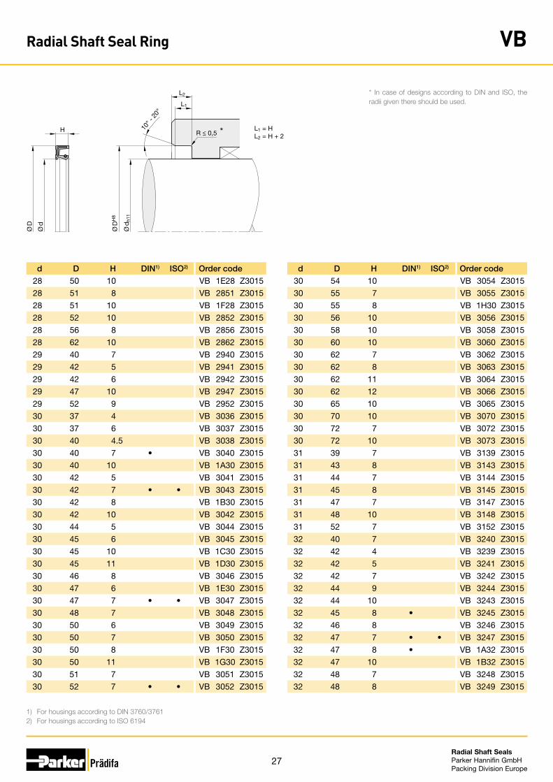
Radial Shaft Seal Ring VB
27Radial Shaft Seals Parker Hannifin GmbHPacking Division Europe
d D H DIN1) ISO2) Order code
28 50 10 VB 1E28 Z3015
28 51 8 VB 2851 Z3015
28 51 10 VB 1F28 Z3015
28 52 10 VB 2852 Z3015
28 56 8 VB 2856 Z3015
28 62 10 VB 2862 Z3015
29 40 7 VB 2940 Z3015
29 42 5 VB 2941 Z3015
29 42 6 VB 2942 Z3015
29 47 10 VB 2947 Z3015
29 52 9 VB 2952 Z3015
30 37 4 VB 3036 Z3015
30 37 6 VB 3037 Z3015
30 40 4.5 VB 3038 Z3015
30 40 7 • VB 3040 Z3015
30 40 10 VB 1A30 Z3015
30 42 5 VB 3041 Z3015
30 42 7 • • VB 3043 Z3015
30 42 8 VB 1B30 Z3015
30 42 10 VB 3042 Z3015
30 44 5 VB 3044 Z3015
30 45 6 VB 3045 Z3015
30 45 10 VB 1C30 Z3015
30 45 11 VB 1D30 Z3015
30 46 8 VB 3046 Z3015
30 47 6 VB 1E30 Z3015
30 47 7 • • VB 3047 Z3015
30 48 7 VB 3048 Z3015
30 50 6 VB 3049 Z3015
30 50 7 VB 3050 Z3015
30 50 8 VB 1F30 Z3015
30 50 11 VB 1G30 Z3015
30 51 7 VB 3051 Z3015
30 52 7 • • VB 3052 Z3015
d D H DIN1) ISO2) Order code
30 54 10 VB 3054 Z3015
30 55 7 VB 3055 Z3015
30 55 8 VB 1H30 Z3015
30 56 10 VB 3056 Z3015
30 58 10 VB 3058 Z3015
30 60 10 VB 3060 Z3015
30 62 7 VB 3062 Z3015
30 62 8 VB 3063 Z3015
30 62 11 VB 3064 Z3015
30 62 12 VB 3066 Z3015
30 65 10 VB 3065 Z3015
30 70 10 VB 3070 Z3015
30 72 7 VB 3072 Z3015
30 72 10 VB 3073 Z3015
31 39 7 VB 3139 Z3015
31 43 8 VB 3143 Z3015
31 44 7 VB 3144 Z3015
31 45 8 VB 3145 Z3015
31 47 7 VB 3147 Z3015
31 48 10 VB 3148 Z3015
31 52 7 VB 3152 Z3015
32 40 7 VB 3240 Z3015
32 42 4 VB 3239 Z3015
32 42 5 VB 3241 Z3015
32 42 7 VB 3242 Z3015
32 44 9 VB 3244 Z3015
32 44 10 VB 3243 Z3015
32 45 8 • VB 3245 Z3015
32 46 8 VB 3246 Z3015
32 47 7 • • VB 3247 Z3015
32 47 8 • VB 1A32 Z3015
32 47 10 VB 1B32 Z3015
32 48 7 VB 3248 Z3015
32 48 8 VB 3249 Z3015
1) For housings according to DIN 3760/37612) For housings according to ISO 6194
L1
L2
H 10° -
20°
R ≤ 0,5
Ø D
H8
Ø d
h11
Ø D
Ø d
L1 = HL2 = H + 2
*
* In case of designs according to DIN and ISO, the radii given there should be used.
Radial Shaft Seal Ring VB
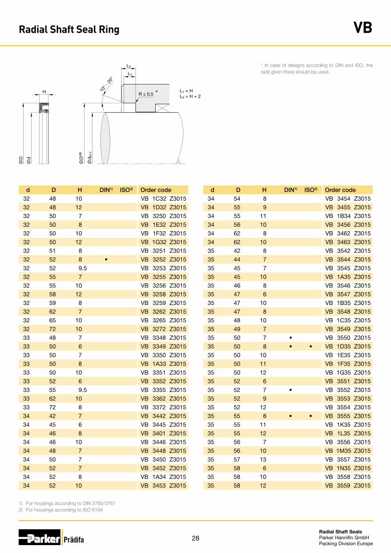
28Radial Shaft Seals Parker Hannifin GmbHPacking Division Europe
d D H DIN1) ISO2) Order code
32 48 10 VB 1C32 Z3015
32 48 12 VB 1D32 Z3015
32 50 7 VB 3250 Z3015
32 50 8 VB 1E32 Z3015
32 50 10 VB 1F32 Z3015
32 50 12 VB 1G32 Z3015
32 51 8 VB 3251 Z3015
32 52 8 • VB 3252 Z3015
32 52 9.5 VB 3253 Z3015
32 55 7 VB 3255 Z3015
32 55 10 VB 3256 Z3015
32 58 12 VB 3258 Z3015
32 59 8 VB 3259 Z3015
32 62 7 VB 3262 Z3015
32 65 10 VB 3265 Z3015
32 72 10 VB 3272 Z3015
33 48 7 VB 3348 Z3015
33 50 6 VB 3349 Z3015
33 50 7 VB 3350 Z3015
33 50 8 VB 1A33 Z3015
33 50 10 VB 3351 Z3015
33 52 6 VB 3352 Z3015
33 55 9.5 VB 3355 Z3015
33 62 10 VB 3362 Z3015
33 72 8 VB 3372 Z3015
34 42 7 VB 3442 Z3015
34 45 6 VB 3445 Z3015
34 46 8 VB 3401 Z3015
34 46 10 VB 3446 Z3015
34 48 7 VB 3448 Z3015
34 50 7 VB 3450 Z3015
34 52 7 VB 3452 Z3015
34 52 8 VB 1A34 Z3015
34 52 10 VB 3453 Z3015
d D H DIN1) ISO2) Order code
34 54 8 VB 3454 Z3015
34 55 9 VB 3455 Z3015
34 55 11 VB 1B34 Z3015
34 56 10 VB 3456 Z3015
34 62 8 VB 3462 Z3015
34 62 10 VB 3463 Z3015
35 42 8 VB 3542 Z3015
35 44 7 VB 3544 Z3015
35 45 7 VB 3545 Z3015
35 45 10 VB 1A35 Z3015
35 46 8 VB 3546 Z3015
35 47 6 VB 3547 Z3015
35 47 10 VB 1B35 Z3015
35 47 8 VB 3548 Z3015
35 48 10 VB 1C35 Z3015
35 49 7 VB 3549 Z3015
35 50 7 • VB 3550 Z3015
35 50 8 • • VB 1D35 Z3015
35 50 10 VB 1E35 Z3015
35 50 11 VB 1F35 Z3015
35 50 12 VB 1G35 Z3015
35 52 6 VB 3551 Z3015
35 52 7 • VB 3552 Z3015
35 52 9 VB 3553 Z3015
35 52 12 VB 3554 Z3015
35 55 8 • • VB 3555 Z3015
35 55 11 VB 1K35 Z3015
35 55 12 VB 1L35 Z3015
35 56 7 VB 3556 Z3015
35 56 10 VB 1M35 Z3015
35 57 13 VB 3557 Z3015
35 58 6 VB 1N35 Z3015
35 58 10 VB 3558 Z3015
35 58 12 VB 3559 Z3015
1) For housings according to DIN 3760/37612) For housings according to ISO 6194
L1
L2
H 10° -
20°
R ≤ 0,5
Ø D
H8
Ø d
h11
Ø D
Ø d
L1 = HL2 = H + 2
*
* In case of designs according to DIN and ISO, the radii given there should be used.
Radial Shaft Seal Ring VB
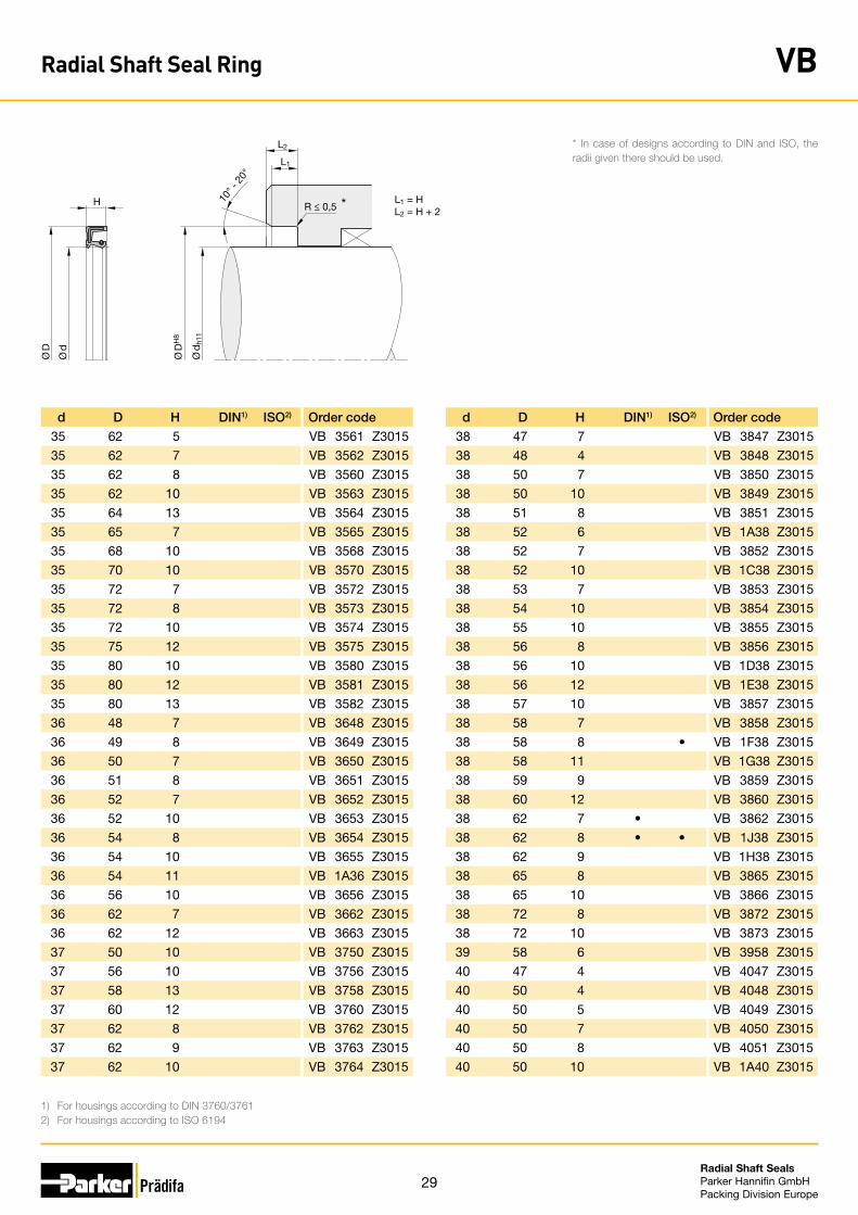
29Radial Shaft Seals Parker Hannifin GmbHPacking Division Europe
d D H DIN1) ISO2) Order code
35 62 5 VB 3561 Z3015
35 62 7 VB 3562 Z3015
35 62 8 VB 3560 Z3015
35 62 10 VB 3563 Z3015
35 64 13 VB 3564 Z3015
35 65 7 VB 3565 Z3015
35 68 10 VB 3568 Z3015
35 70 10 VB 3570 Z3015
35 72 7 VB 3572 Z3015
35 72 8 VB 3573 Z3015
35 72 10 VB 3574 Z3015
35 75 12 VB 3575 Z3015
35 80 10 VB 3580 Z3015
35 80 12 VB 3581 Z3015
35 80 13 VB 3582 Z3015
36 48 7 VB 3648 Z3015
36 49 8 VB 3649 Z3015
36 50 7 VB 3650 Z3015
36 51 8 VB 3651 Z3015
36 52 7 VB 3652 Z3015
36 52 10 VB 3653 Z3015
36 54 8 VB 3654 Z3015
36 54 10 VB 3655 Z3015
36 54 11 VB 1A36 Z3015
36 56 10 VB 3656 Z3015
36 62 7 VB 3662 Z3015
36 62 12 VB 3663 Z3015
37 50 10 VB 3750 Z3015
37 56 10 VB 3756 Z3015
37 58 13 VB 3758 Z3015
37 60 12 VB 3760 Z3015
37 62 8 VB 3762 Z3015
37 62 9 VB 3763 Z3015
37 62 10 VB 3764 Z3015
d D H DIN1) ISO2) Order code
38 47 7 VB 3847 Z3015
38 48 4 VB 3848 Z3015
38 50 7 VB 3850 Z3015
38 50 10 VB 3849 Z3015
38 51 8 VB 3851 Z3015
38 52 6 VB 1A38 Z3015
38 52 7 VB 3852 Z3015
38 52 10 VB 1C38 Z3015
38 53 7 VB 3853 Z3015
38 54 10 VB 3854 Z3015
38 55 10 VB 3855 Z3015
38 56 8 VB 3856 Z3015
38 56 10 VB 1D38 Z3015
38 56 12 VB 1E38 Z3015
38 57 10 VB 3857 Z3015
38 58 7 VB 3858 Z3015
38 58 8 • VB 1F38 Z3015
38 58 11 VB 1G38 Z3015
38 59 9 VB 3859 Z3015
38 60 12 VB 3860 Z3015
38 62 7 • VB 3862 Z3015
38 62 8 • • VB 1J38 Z3015
38 62 9 VB 1H38 Z3015
38 65 8 VB 3865 Z3015
38 65 10 VB 3866 Z3015
38 72 8 VB 3872 Z3015
38 72 10 VB 3873 Z3015
39 58 6 VB 3958 Z3015
40 47 4 VB 4047 Z3015
40 50 4 VB 4048 Z3015
40 50 5 VB 4049 Z3015
40 50 7 VB 4050 Z3015
40 50 8 VB 4051 Z3015
40 50 10 VB 1A40 Z3015
1) For housings according to DIN 3760/37612) For housings according to ISO 6194
L1
L2
H 10° -
20°
R ≤ 0,5
Ø D
H8
Ø d
h11
Ø D
Ø d
L1 = HL2 = H + 2
*
* In case of designs according to DIN and ISO, the radii given there should be used.
Radial Shaft Seal Ring VB

30Radial Shaft Seals Parker Hannifin GmbHPacking Division Europe
d D H DIN1) ISO2) Order code
40 52 5 VB 4052 Z3015
40 52 8.5 VB 1B40 Z3015
40 52 10 VB 1C40 Z3015
40 53 7 VB 4053 Z3015
40 53 8 VB 1D40 Z3015
40 54 7 VB 4054 Z3015
40 55 7 • VB 4055 Z3015
40 55 10 VB 1E40 Z3015
40 56 7 VB 4056 Z3015
40 56 8 VB 1F40 Z3015
40 56 10 VB 1G40 Z3015
40 56 12 VB 1H40 Z3015
40 57 10 VB 4057 Z3015
40 58 7 VB 4058 Z3015
40 58 8 VB 4059 Z3015
40 58 10 VB 1K40 Z3015
40 60 7 VB 4060 Z3015
40 60 10 VB 4061 Z3015
40 60 12 VB 1L40 Z3015
40 62 5 VB 4062 Z3015
40 62 7 • VB 4063 Z3015
40 62 8 • • VB 4008 Z3015
40 62 11 VB 1M40 Z3015
40 64 12 VB 4064 Z3015
40 65 8 VB 4065 Z3015
40 67 10 VB 4067 Z3015
40 68 5 VB 4066 Z3015
40 68 7 VB 4068 Z3015
40 68 10 VB 4069 Z3015
40 70 7 VB 4070 Z3015
40 70 10 VB 4071 Z3015
40 72 7 VB 4072 Z3015
40 72 12 VB 4073 Z3015
40 74 10 VB 4074 Z3015
d D H DIN1) ISO2) Order code
40 75 12 VB 4075 Z3015
40 80 7 VB 4080 Z3015
40 80 10 VB 4081 Z3015
40 85 10 VB 4085 Z3015
40 90 8 VB 4090 Z3015
40 90 12 VB 4091 Z3015
42 50 7 VB 4250 Z3015
42 51 7 VB 4251 Z3015
42 52 7 VB 4252 Z3015
42 55 6 VB 4254 Z3015
42 55 7 VB 4255 Z3015
42 55 8 • • VB 1A42 Z3015
42 55 9 VB 1B42 Z3015
42 56 7 VB 4256 Z3015
42 57 10 VB 4257 Z3015
42 58 7 VB 4258 Z3015
42 58 10 VB 1C42 Z3015
42 59 7 VB 4259 Z3015
42 60 7 VB 4260 Z3015
42 60 10 VB 4261 Z3015
42 62 7 VB 4262 Z3015
42 62 10 VB 1D42 Z3015
42 62 12 VB 1E42 Z3015
42 63 8 VB 4263 Z3015
42 64 10 VB 4264 Z3015
42 65 7 VB 4265 Z3015
42 65 8 VB 1G42 Z3015
42 65 9 VB 1H42 Z3015
42 65 10 VB 1J42 Z3015
42 66 8 VB 4266 Z3015
42 66 10 VB 4267 Z3015
42 66 12 VB 4269 Z3015
42 68 10 VB 4268 Z3015
42 72 7 VB 4272 Z3015
1) For housings according to DIN 3760/37612) For housings according to ISO 6194
L1
L2
H 10° -
20°
R ≤ 0,5
Ø D
H8
Ø d
h11
Ø D
Ø d
L1 = HL2 = H + 2
*
* In case of designs according to DIN and ISO, the radii given there should be used.
Radial Shaft Seal Ring VB
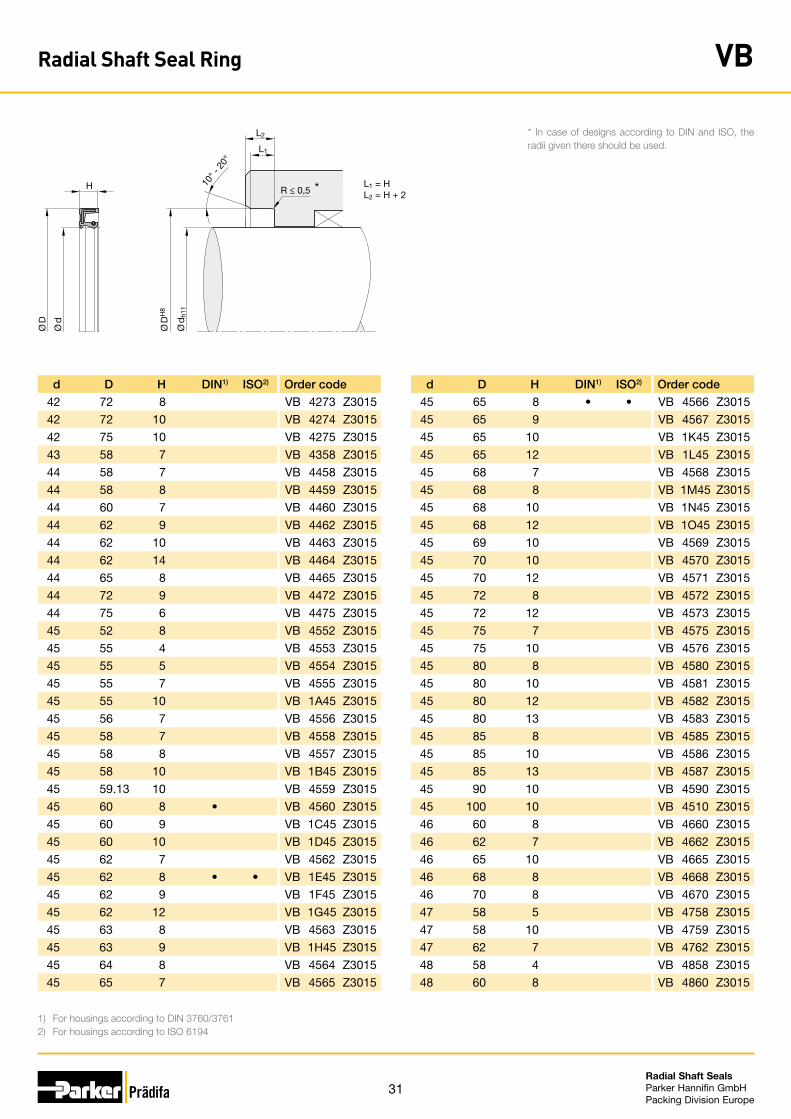
31Radial Shaft Seals Parker Hannifin GmbHPacking Division Europe
d D H DIN1) ISO2) Order code
42 72 8 VB 4273 Z3015
42 72 10 VB 4274 Z3015
42 75 10 VB 4275 Z3015
43 58 7 VB 4358 Z3015
44 58 7 VB 4458 Z3015
44 58 8 VB 4459 Z3015
44 60 7 VB 4460 Z3015
44 62 9 VB 4462 Z3015
44 62 10 VB 4463 Z3015
44 62 14 VB 4464 Z3015
44 65 8 VB 4465 Z3015
44 72 9 VB 4472 Z3015
44 75 6 VB 4475 Z3015
45 52 8 VB 4552 Z3015
45 55 4 VB 4553 Z3015
45 55 5 VB 4554 Z3015
45 55 7 VB 4555 Z3015
45 55 10 VB 1A45 Z3015
45 56 7 VB 4556 Z3015
45 58 7 VB 4558 Z3015
45 58 8 VB 4557 Z3015
45 58 10 VB 1B45 Z3015
45 59.13 10 VB 4559 Z3015
45 60 8 • VB 4560 Z3015
45 60 9 VB 1C45 Z3015
45 60 10 VB 1D45 Z3015
45 62 7 VB 4562 Z3015
45 62 8 • • VB 1E45 Z3015
45 62 9 VB 1F45 Z3015
45 62 12 VB 1G45 Z3015
45 63 8 VB 4563 Z3015
45 63 9 VB 1H45 Z3015
45 64 8 VB 4564 Z3015
45 65 7 VB 4565 Z3015
d D H DIN1) ISO2) Order code
45 65 8 • • VB 4566 Z3015
45 65 9 VB 4567 Z3015
45 65 10 VB 1K45 Z3015
45 65 12 VB 1L45 Z3015
45 68 7 VB 4568 Z3015
45 68 8 VB 1M45 Z3015
45 68 10 VB 1N45 Z3015
45 68 12 VB 1O45 Z3015
45 69 10 VB 4569 Z3015
45 70 10 VB 4570 Z3015
45 70 12 VB 4571 Z3015
45 72 8 VB 4572 Z3015
45 72 12 VB 4573 Z3015
45 75 7 VB 4575 Z3015
45 75 10 VB 4576 Z3015
45 80 8 VB 4580 Z3015
45 80 10 VB 4581 Z3015
45 80 12 VB 4582 Z3015
45 80 13 VB 4583 Z3015
45 85 8 VB 4585 Z3015
45 85 10 VB 4586 Z3015
45 85 13 VB 4587 Z3015
45 90 10 VB 4590 Z3015
45 100 10 VB 4510 Z3015
46 60 8 VB 4660 Z3015
46 62 7 VB 4662 Z3015
46 65 10 VB 4665 Z3015
46 68 8 VB 4668 Z3015
46 70 8 VB 4670 Z3015
47 58 5 VB 4758 Z3015
47 58 10 VB 4759 Z3015
47 62 7 VB 4762 Z3015
48 58 4 VB 4858 Z3015
48 60 8 VB 4860 Z3015
1) For housings according to DIN 3760/37612) For housings according to ISO 6194
L1
L2
H 10° -
20°
R ≤ 0,5
Ø D
H8
Ø d
h11
Ø D
Ø d
L1 = HL2 = H + 2
*
* In case of designs according to DIN and ISO, the radii given there should be used.
Radial Shaft Seal Ring VB
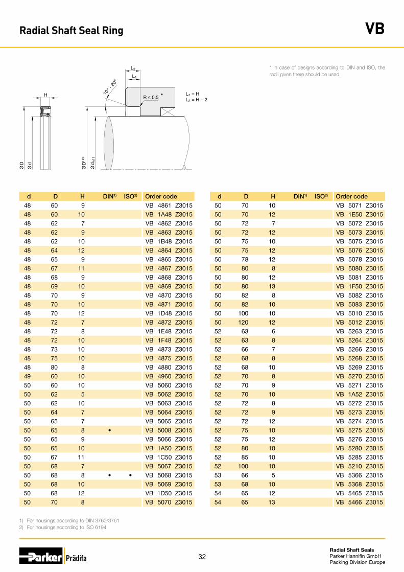
32Radial Shaft Seals Parker Hannifin GmbHPacking Division Europe
d D H DIN1) ISO2) Order code
48 60 9 VB 4861 Z3015
48 60 10 VB 1A48 Z3015
48 62 7 VB 4862 Z3015
48 62 9 VB 4863 Z3015
48 62 10 VB 1B48 Z3015
48 64 12 VB 4864 Z3015
48 65 9 VB 4865 Z3015
48 67 11 VB 4867 Z3015
48 68 9 VB 4868 Z3015
48 69 10 VB 4869 Z3015
48 70 9 VB 4870 Z3015
48 70 10 VB 4871 Z3015
48 70 12 VB 1D48 Z3015
48 72 7 VB 4872 Z3015
48 72 8 VB 1E48 Z3015
48 72 10 VB 1F48 Z3015
48 73 10 VB 4873 Z3015
48 75 10 VB 4875 Z3015
48 80 8 VB 4880 Z3015
49 60 10 VB 4960 Z3015
50 60 10 VB 5060 Z3015
50 62 5 VB 5062 Z3015
50 62 10 VB 5063 Z3015
50 64 7 VB 5064 Z3015
50 65 7 VB 5065 Z3015
50 65 8 • VB 5008 Z3015
50 65 9 VB 5066 Z3015
50 65 10 VB 1A50 Z3015
50 67 11 VB 1C50 Z3015
50 68 7 VB 5067 Z3015
50 68 8 • • VB 5068 Z3015
50 68 10 VB 5069 Z3015
50 68 12 VB 1D50 Z3015
50 70 8 VB 5070 Z3015
d D H DIN1) ISO2) Order code
50 70 10 VB 5071 Z3015
50 70 12 VB 1E50 Z3015
50 72 7 VB 5072 Z3015
50 72 12 VB 5073 Z3015
50 75 10 VB 5075 Z3015
50 75 12 VB 5076 Z3015
50 78 12 VB 5078 Z3015
50 80 8 VB 5080 Z3015
50 80 12 VB 5081 Z3015
50 80 13 VB 1F50 Z3015
50 82 8 VB 5082 Z3015
50 82 10 VB 5083 Z3015
50 100 10 VB 5010 Z3015
50 120 12 VB 5012 Z3015
52 63 6 VB 5263 Z3015
52 63 8 VB 5264 Z3015
52 66 7 VB 5266 Z3015
52 68 8 VB 5268 Z3015
52 68 10 VB 5269 Z3015
52 70 8 VB 5270 Z3015
52 70 9 VB 5271 Z3015
52 70 10 VB 1A52 Z3015
52 72 8 VB 5272 Z3015
52 72 9 VB 5273 Z3015
52 72 12 VB 5274 Z3015
52 75 10 VB 5275 Z3015
52 75 12 VB 5276 Z3015
52 80 10 VB 5280 Z3015
52 85 10 VB 5285 Z3015
52 100 10 VB 5210 Z3015
53 66 5 VB 5366 Z3015
53 68 10 VB 5368 Z3015
54 65 12 VB 5465 Z3015
54 65 13 VB 5466 Z3015
1) For housings according to DIN 3760/37612) For housings according to ISO 6194
* In case of designs according to DIN and ISO, the radii given there should be used.L1
L2
H 10° -
20°
R ≤ 0,5
Ø D
H8
Ø d
h11
Ø D
Ø d
L1 = HL2 = H + 2
*
Radial Shaft Seal Ring VB

33Radial Shaft Seals Parker Hannifin GmbHPacking Division Europe
d D H DIN1) ISO2) Order code
54 68 9 VB 5468 Z3015
54 72.5 9 VB 5472 Z3015
54 85 10 VB 5485 Z3015
55 62 8 VB 5562 Z3015
55 65 8 VB 5565 Z3015
55 67 6 VB 5567 Z3015
55 68 8 VB 5568 Z3015
55 68 8.5 VB 5569 Z3015
55 70 8 • VB 5570 Z3015
55 70 9 VB 5571 Z3015
55 70 10 VB 1A55 Z3015
55 72 7 VB 5572 Z3015
55 72 8 • • VB 1B55 Z3015
55 72 9 VB 1C55 Z3015
55 72 12 VB 1D55 Z3015
55 73 10 VB 5573 Z3015
55 75 8 VB 5575 Z3015
55 75 9 VB 5576 Z3015
55 75 12 VB 5577 Z3015
55 78 10 VB 5578 Z3015
55 78 12 VB 5579 Z3015
55 80 10 VB 5580 Z3015
55 80 13 VB 5581 Z3015
55 82 12 VB 5582 Z3015
55 85 8 VB 5585 Z3015
55 85 10 VB 5586 Z3015
55 90 13 VB 5590 Z3015
55 90 15 VB 5591 Z3015
55 100 10 VB 5510 Z3015
55 100 12 VB 5511 Z3015
56 72 8 VB 5672 Z3015
56 76 10 VB 5676 Z3015
56 85 8 VB 5685 Z3015
56 90 10 VB 5690 Z3015
d D H DIN1) ISO2) Order code
57 86 5 VB 5785 Z3015
57 86 6 VB 5786 Z3015
57 86 6.5 VB 5587 Z3015
58 75 9 VB 5875 Z3015
58 75 10 VB 5876 Z3015
58 80 12 VB 5880 Z3015
58 82 10 VB 5882 Z3015
58 85 10 VB 5885 Z3015
58 90 10 VB 5890 Z3015
58 90 13 VB 5891 Z3015
58 90 15 VB 5892 Z3015
59 78 10 VB 5978 Z3015
60 70 7 VB 6070 Z3015
60 72 8 VB 6072 Z3015
60 72 10 VB 6073 Z3015
60 72 12 VB 1A60 Z3015
60 74 10 VB 6074 Z3015
60 75 8 • VB 6075 Z3015
60 75 10 VB 6076 Z3015
60 77 12 VB 6077 Z3015
60 80 7 VB 6080 Z3015
60 80 12 VB 6081 Z3015
60 82 12 VB 6082 Z3015
60 85 8 • • VB 6085 Z3015
60 85 13 VB 6086 Z3015
60 90 10 VB 6090 Z3015
60 92 10 VB 6092 Z3015
60 95 8 VB 6095 Z3015
60 95 10 VB 6096 Z3015
60 95 12 VB 6097 Z3015
60 100 10 VB 6010 Z3015
60 100 10 VB 6011 Z3015
60 100 13 VB 6012 Z3015
60 110 12 VB 6013 Z3015
1) For housings according to DIN 3760/37612) For housings according to ISO 6194
* In case of designs according to DIN and ISO, the radii given there should be used.L1
L2
H 10° -
20°
R ≤ 0,5
Ø D
H8
Ø d
h11
Ø D
Ø d
L1 = HL2 = H + 2
*
Radial Shaft Seal Ring VB

34Radial Shaft Seals Parker Hannifin GmbHPacking Division Europe
d D H DIN1) ISO2) Order code
62 76 10 VB 6276 Z3015
62 80 8 VB 6280 Z3015
62 80 9 VB 6181 Z3015
62 80 10 VB 1A62 Z3015
62 82 10 VB 6282 Z3015
62 85 7 VB 6285 Z3015
62 85 10 VB 6286 Z3015
62 90 10 VB 6290 Z3015
62 90 13 VB 6291 Z3015
62 95 10 VB 6295 Z3015
62 95 13 VB 6296 Z3015
62 120 12 VB 6212 Z3015
63 88 12 VB 6388 Z3015
63 90 8 VB 6390 Z3015
63 90 10 VB 6391 Z3015
63 100 13 VB 6310 Z3015
63.5 95.2 12.7 VB 6395 Z3015
64 80 8 VB 6480 Z3015
64 80 13 VB 6481 Z3015
65 75 5 VB 6575 Z3015
65 75 10 VB 6576 Z3015
65 80 10 VB 6580 Z3015
65 80 12 VB 6581 Z3015
65 85 12 VB 6585 Z3015
65 85 13 VB 6586 Z3015
65 88 8 VB 6588 Z3015
65 88 12 VB 6589 Z3015
65 88 16.5 VB 1A65 Z3015
65 90 10 • • VB 6590 Z3015
65 90 13 VB 6591 Z3015
65 95 10 VB 6595 Z3015
65 95 12 VB 6596 Z3015
65 95 13 VB 6597 Z3015
65 105 12 VB 6510 Z3015
d D H DIN1) ISO2) Order code
65 110 12 VB 6511 Z3015
65 120 12 VB 6512 Z3015
65 120 13 VB 6513 Z3015
66 90 10 VB 6690 Z3015
68 86 7 VB 6886 Z3015
68 86 8 VB 6887 Z3015
68 88 10 VB 6888 Z3015
68 90 7 VB 6890 Z3015
68 92 10 VB 6892 Z3015
68 100 13 VB 6810 Z3015
68 110 13 VB 6811 Z3015
69.85 88.9 9.525 VB 6889 Z3015
70 80 8 VB 7080 Z3015
70 80 10 VB 7081 Z3015
70 87 10 VB 7087 Z3015
70 88 8 VB 7088 Z3015
70 88 12 VB 7089 Z3015
70 90 12 VB 7090 Z3015
70 95 12 VB 7094 Z3015
70 95 13 VB 7095 Z3015
70 100 10 VB 7010 Z3015
70 100 13 VB 7011 Z3015
70 105 10 VB 7012 Z3015
70 105 12 VB 7013 Z3015
70 105 13 VB 7014 Z3015
70 110 8 VB 7015 Z3015
70 110 12 VB 7016 Z3015
70 120 10 VB 7017 Z3015
71 88 8 VB 7188 Z3015
72 84 7 VB 7284 Z3015
72 86 7 VB 7286 Z3015
72 90 10 VB 7290 Z3015
72 95 10 VB 7295 Z3015
72 100 10 VB 7210 Z3015
1) For housings according to DIN 3760/37612) For housings according to ISO 6194
* In case of designs according to DIN and ISO, the radii given there should be used.L1
L2
H 10° -
20°
R ≤ 0,5
Ø D
H8
Ø d
h11
Ø D
Ø d
L1 = HL2 = H + 2
*
Radial Shaft Seal Ring VB
35Radial Shaft Seals Parker Hannifin GmbHPacking Division Europe
d D H DIN1) ISO2) Order code
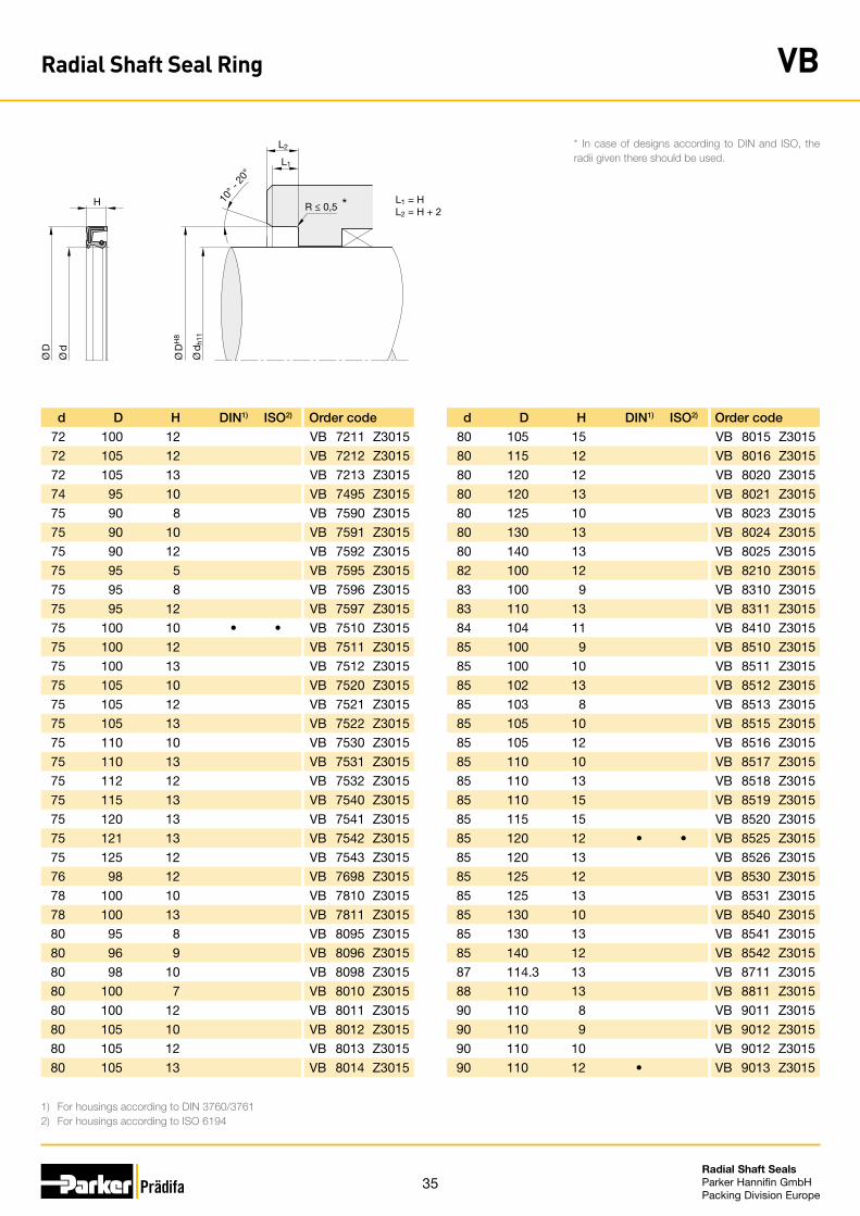
72 100 12 VB 7211 Z3015
72 105 12 VB 7212 Z3015
72 105 13 VB 7213 Z3015
74 95 10 VB 7495 Z3015
75 90 8 VB 7590 Z3015
75 90 10 VB 7591 Z3015
75 90 12 VB 7592 Z3015
75 95 5 VB 7595 Z3015
75 95 8 VB 7596 Z3015
75 95 12 VB 7597 Z3015
75 100 10 • • VB 7510 Z3015
75 100 12 VB 7511 Z3015
75 100 13 VB 7512 Z3015
75 105 10 VB 7520 Z3015
75 105 12 VB 7521 Z3015
75 105 13 VB 7522 Z3015
75 110 10 VB 7530 Z3015
75 110 13 VB 7531 Z3015
75 112 12 VB 7532 Z3015
75 115 13 VB 7540 Z3015
75 120 13 VB 7541 Z3015
75 121 13 VB 7542 Z3015
75 125 12 VB 7543 Z3015
76 98 12 VB 7698 Z3015
78 100 10 VB 7810 Z3015
78 100 13 VB 7811 Z3015
80 95 8 VB 8095 Z3015
80 96 9 VB 8096 Z3015
80 98 10 VB 8098 Z3015
80 100 7 VB 8010 Z3015
80 100 12 VB 8011 Z3015
80 105 10 VB 8012 Z3015
80 105 12 VB 8013 Z3015
80 105 13 VB 8014 Z3015
d D H DIN1) ISO2) Order code
80 105 15 VB 8015 Z3015
80 115 12 VB 8016 Z3015
80 120 12 VB 8020 Z3015
80 120 13 VB 8021 Z3015
80 125 10 VB 8023 Z3015
80 130 13 VB 8024 Z3015
80 140 13 VB 8025 Z3015
82 100 12 VB 8210 Z3015
83 100 9 VB 8310 Z3015
83 110 13 VB 8311 Z3015
84 104 11 VB 8410 Z3015
85 100 9 VB 8510 Z3015
85 100 10 VB 8511 Z3015
85 102 13 VB 8512 Z3015
85 103 8 VB 8513 Z3015
85 105 10 VB 8515 Z3015
85 105 12 VB 8516 Z3015
85 110 10 VB 8517 Z3015
85 110 13 VB 8518 Z3015
85 110 15 VB 8519 Z3015
85 115 15 VB 8520 Z3015
85 120 12 • • VB 8525 Z3015
85 120 13 VB 8526 Z3015
85 125 12 VB 8530 Z3015
85 125 13 VB 8531 Z3015
85 130 10 VB 8540 Z3015
85 130 13 VB 8541 Z3015
85 140 12 VB 8542 Z3015
87 114.3 13 VB 8711 Z3015
88 110 13 VB 8811 Z3015
90 110 8 VB 9011 Z3015
90 110 9 VB 9012 Z3015
90 110 10 VB 9012 Z3015
90 110 12 • VB 9013 Z3015
1) For housings according to DIN 3760/37612) For housings according to ISO 6194
* In case of designs according to DIN and ISO, the radii given there should be used.L1
L2
H 10° -
20°
R ≤ 0,5
Ø D
H8
Ø d
h11
Ø D
Ø d
L1 = HL2 = H + 2
*
Radial Shaft Seal Ring VB
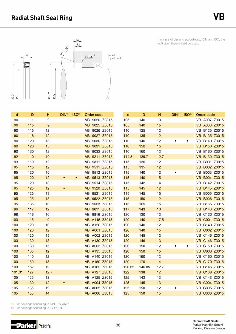
36Radial Shaft Seals Parker Hannifin GmbHPacking Division Europe
d D H DIN1) ISO2) Order code
90 111 9 VB 9020 Z3015
90 115 9 VB 9025 Z3015
90 115 12 VB 9026 Z3015
90 118 12 VB 9027 Z3015
90 120 13 VB 9030 Z3015
90 120 15 VB 9031 Z3015
90 130 12 VB 9032 Z3015
92 110 10 VB 9211 Z3015
93 110 12 VB 9311 Z3015
95 115 12 VB 9511 Z3015
95 120 10 VB 9512 Z3015
95 120 12 • • VB 9513 Z3015
95 120 13 VB 9514 Z3015
95 125 12 • VB 9520 Z3015
95 125 13 VB 9521 Z3015
95 125 15 VB 9522 Z3015
95 135 13 VB 9523 Z3015
96 117 12 VB 9611 Z3015
98 116 10 VB 9816 Z3015
100 115 9 VB A115 Z3015
100 120 10 VB A120 Z3015
100 120 12 VB A001 Z3015
100 120 15 VB A002 Z3015
100 130 13 VB A130 Z3015
100 130 15 VB A003 Z3015
100 135 12 VB A135 Z3015
100 140 12 VB A140 Z3015
100 150 13 VB A150 Z3015
100 162 12 VB A162 Z3015
101.01 127 12.7 VB A127 Z3015
105 125 13 VB A125 Z3015
105 130 12 • VB A004 Z3015
105 135 12 VB A005 Z3015
105 135 14 VB A006 Z3015
d D H DIN1) ISO2) Order code
105 140 13 VB A007 Z3015
105 140 15 VB A008 Z3015
110 125 12 VB B125 Z3015
110 135 12 VB B135 Z3015
110 140 12 • • VB B140 Z3015
110 150 15 VB B150 Z3015
110 160 12 VB B160 Z3015
114.3 139.7 12.7 VB B139 Z3015
115 130 12 VB B001 Z3015
115 135 12 VB B002 Z3015
115 140 12 • VB B003 Z3015
115 140 15 VB B004 Z3015
115 142 14 VB B142 Z3015
115 145 12 VB B145 Z3015
115 145 15 VB B005 Z3015
115 150 12 VB B006 Z3015
115 165 15 VB B165 Z3015
117 143 13 VB B143 Z3015
120 130 13 VB C130 Z3015
120 140 7.5 VB C001 Z3015
120 140 12 VB C140 Z3015
120 140 15 VB C002 Z3015
120 145 12 VB C145 Z3015
120 146 13 VB C146 Z3015
120 150 12 • • VB C150 Z3015
120 150 15 VB C003 Z3015
120 160 12 VB C160 Z3015
120 170 14 VB C170 Z3015
120.65 146.05 12.7 VB C146 Z3015
122 138 12 VB C138 Z3015
125 143 13 VB C143 Z3015
125 145 13 VB C004 Z3015
125 150 12 • VB C005 Z3015
125 150 15 VB C006 Z3015
1) For housings according to DIN 3760/37612) For housings according to ISO 6194
* In case of designs according to DIN and ISO, the radii given there should be used.L1
L2
H 10° -
20°
R ≤ 0,5
Ø D
H8
Ø d
h11
Ø D
Ø d
L1 = HL2 = H + 2
*
Radial Shaft Seal Ring VB
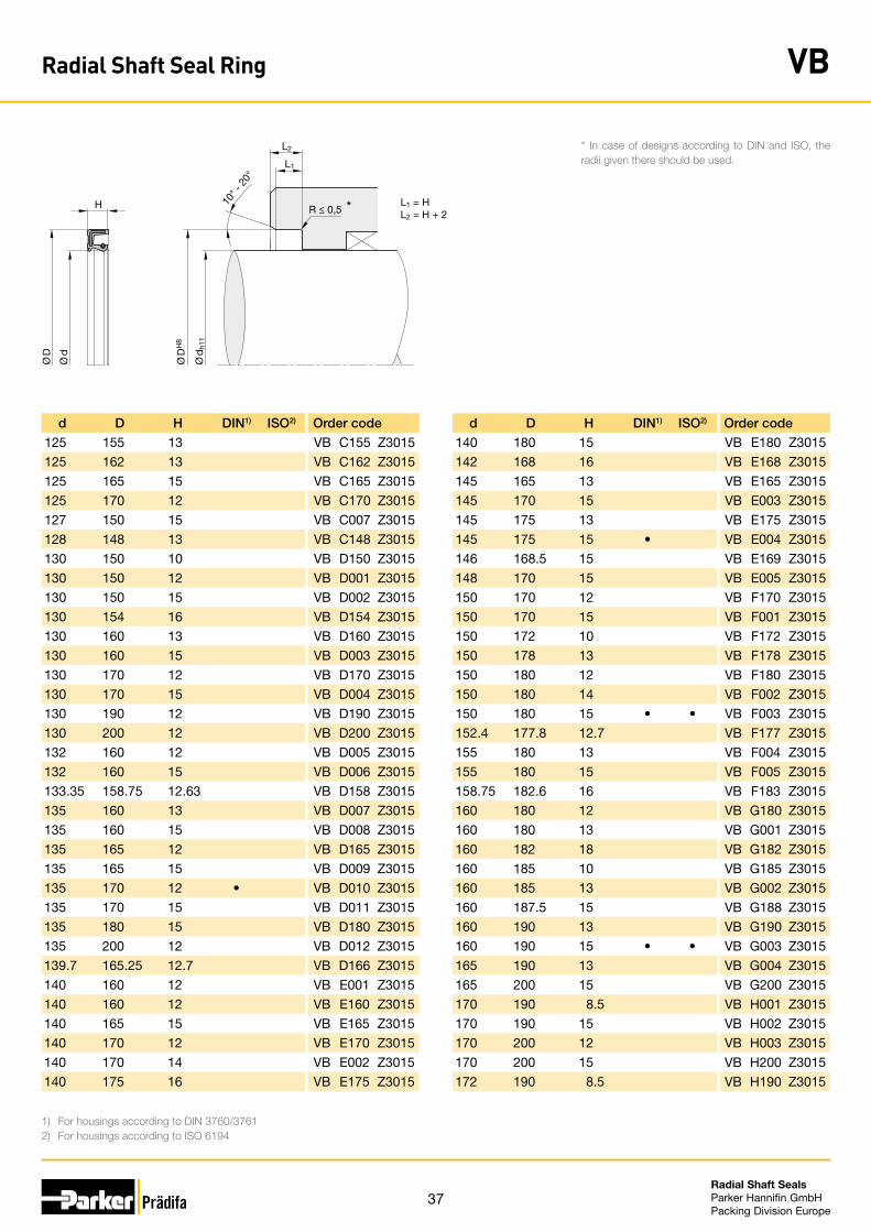
37Radial Shaft Seals Parker Hannifin GmbHPacking Division Europe
d D H DIN1) ISO2) Order code
125 155 13 VB C155 Z3015
125 162 13 VB C162 Z3015
125 165 15 VB C165 Z3015
125 170 12 VB C170 Z3015
127 150 15 VB C007 Z3015
128 148 13 VB C148 Z3015
130 150 10 VB D150 Z3015
130 150 12 VB D001 Z3015
130 150 15 VB D002 Z3015
130 154 16 VB D154 Z3015
130 160 13 VB D160 Z3015
130 160 15 VB D003 Z3015
130 170 12 VB D170 Z3015
130 170 15 VB D004 Z3015
130 190 12 VB D190 Z3015
130 200 12 VB D200 Z3015
132 160 12 VB D005 Z3015
132 160 15 VB D006 Z3015
133.35 158.75 12.63 VB D158 Z3015
135 160 13 VB D007 Z3015
135 160 15 VB D008 Z3015
135 165 12 VB D165 Z3015
135 165 15 VB D009 Z3015
135 170 12 • VB D010 Z3015
135 170 15 VB D011 Z3015
135 180 15 VB D180 Z3015
135 200 12 VB D012 Z3015
139.7 165.25 12.7 VB D166 Z3015
140 160 12 VB E001 Z3015
140 160 12 VB E160 Z3015
140 165 15 VB E165 Z3015
140 170 12 VB E170 Z3015
140 170 14 VB E002 Z3015
140 175 16 VB E175 Z3015
d D H DIN1) ISO2) Order code
140 180 15 VB E180 Z3015
142 168 16 VB E168 Z3015
145 165 13 VB E165 Z3015
145 170 15 VB E003 Z3015
145 175 13 VB E175 Z3015
145 175 15 • VB E004 Z3015
146 168.5 15 VB E169 Z3015
148 170 15 VB E005 Z3015
150 170 12 VB F170 Z3015
150 170 15 VB F001 Z3015
150 172 10 VB F172 Z3015
150 178 13 VB F178 Z3015
150 180 12 VB F180 Z3015
150 180 14 VB F002 Z3015
150 180 15 • • VB F003 Z3015
152.4 177.8 12.7 VB F177 Z3015
155 180 13 VB F004 Z3015
155 180 15 VB F005 Z3015
158.75 182.6 16 VB F183 Z3015
160 180 12 VB G180 Z3015
160 180 13 VB G001 Z3015
160 182 18 VB G182 Z3015
160 185 10 VB G185 Z3015
160 185 13 VB G002 Z3015
160 187.5 15 VB G188 Z3015
160 190 13 VB G190 Z3015
160 190 15 • • VB G003 Z3015
165 190 13 VB G004 Z3015
165 200 15 VB G200 Z3015
170 190 8.5 VB H001 Z3015
170 190 15 VB H002 Z3015
170 200 12 VB H003 Z3015
170 200 15 VB H200 Z3015
172 190 8.5 VB H190 Z3015
1) For housings according to DIN 3760/37612) For housings according to ISO 6194
* In case of designs according to DIN and ISO, the radii given there should be used.L1
L2
H 10° -
20°
R ≤ 0,5
Ø D
H8
Ø d
h11
Ø D
Ø d
L1 = HL2 = H + 2
*
Radial Shaft Seal Ring VB
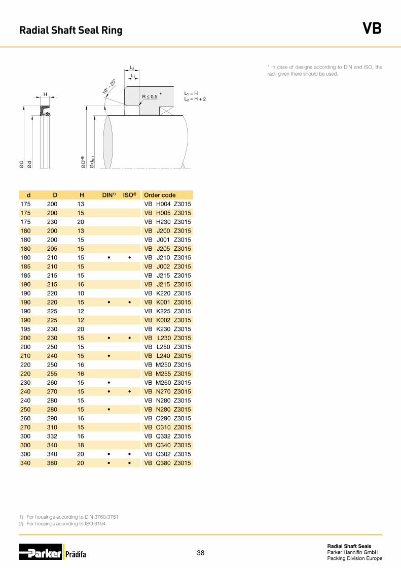
38Radial Shaft Seals Parker Hannifin GmbHPacking Division Europe
d D H DIN1) ISO2) Order code
175 200 13 VB H004 Z3015
175 200 15 VB H005 Z3015
175 230 20 VB H230 Z3015
180 200 13 VB J200 Z3015
180 200 15 VB J001 Z3015
180 205 15 VB J205 Z3015
180 210 15 • • VB J210 Z3015
185 210 15 VB J002 Z3015
185 215 15 VB J215 Z3015
190 215 16 VB J215 Z3015
190 220 10 VB K220 Z3015
190 220 15 • • VB K001 Z3015
190 225 12 VB K225 Z3015
190 225 12 VB K002 Z3015
195 230 20 VB K230 Z3015
200 230 15 • • VB L230 Z3015
200 250 15 VB L250 Z3015
210 240 15 • VB L240 Z3015
220 250 16 VB M250 Z3015
220 255 16 VB M255 Z3015
230 260 15 • VB M260 Z3015
240 270 15 • • VB N270 Z3015
240 280 15 VB N280 Z3015
250 280 15 • VB N280 Z3015
260 290 16 VB O290 Z3015
270 310 15 VB O310 Z3015
300 332 16 VB Q332 Z3015
300 340 18 VB Q340 Z3015
300 340 20 • • VB Q302 Z3015
340 380 20 • • VB Q380 Z3015
1) For housings according to DIN 3760/37612) For housings according to ISO 6194
* In case of designs according to DIN and ISO, the radii given there should be used.L1
L2
H 10° -
20°
R ≤ 0,5
Ø D
H8
Ø d
h11
Ø D
Ø d
L1 = HL2 = H + 2
*
Radial Shaft Seal Ring VB
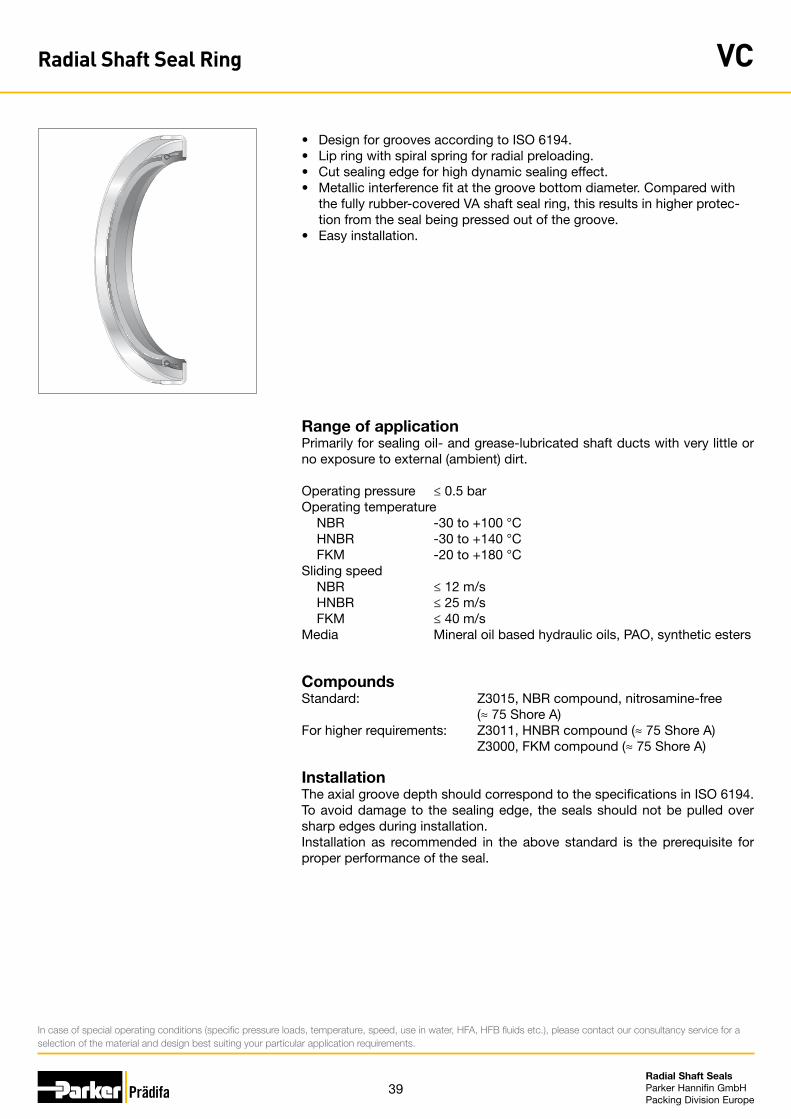
39Radial Shaft Seals Parker Hannifin GmbHPacking Division Europe
• Design for grooves according to ISO 6194.• Lip ring with spiral spring for radial preloading.• Cut sealing edge for high dynamic sealing effect.• Metallic interference fit at the groove bottom diameter. Compared with
the fully rubber-covered VA shaft seal ring, this results in higher protec-tion from the seal being pressed out of the groove.
• Easy installation.
Range of applicationPrimarily for sealing oil- and grease-lubricated shaft ducts with very little or no exposure to external (ambient) dirt.
Operating pressure ≤ 0.5 barOperating temperature NBR -30 to +100 °C HNBR -30 to +140 °C FKM -20 to +180 °CSliding speed NBR ≤ 12 m/s HNBR ≤ 25 m/s FKM ≤ 40 m/sMedia Mineral oil based hydraulic oils, PAO, synthetic esters
CompoundsStandard: Z3015, NBR compound, nitrosamine-free (≈ 75 Shore A)For higher requirements: Z3011, HNBR compound (≈ 75 Shore A) Z3000, FKM compound (≈ 75 Shore A)
InstallationThe axial groove depth should correspond to the specifications in ISO 6194. To avoid damage to the sealing edge, the seals should not be pulled over sharp edges during installation.Installation as recommended in the above standard is the prerequisite for proper performance of the seal.
In case of special operating conditions (specific pressure loads, temperature, speed, use in water, HFA, HFB fluids etc.), please contact our consultancy service for a selection of the material and design best suiting your particular application requirements.
Radial Shaft Seal Ring VC
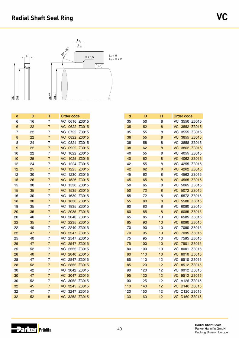
40Radial Shaft Seals Parker Hannifin GmbHPacking Division Europe
L1
L2
H 10° -
20°
R ≤ 0,5
Ø D
H8
Ø d
h11
Ø D
Ø d
L1 = HL2 = H + 2
d D H Order code
6 16 7 VC 0616 Z3015
6 22 7 VC 0622 Z3015
7 22 7 VC 0722 Z3015
8 22 7 VC 0822 Z3015
8 24 7 VC 0824 Z3015
9 22 7 VC 0922 Z3015
10 22 7 VC 1022 Z3015
10 25 7 VC 1025 Z3015
12 24 7 VC 1224 Z3015
12 25 7 VC 1225 Z3015
12 30 7 VC 1230 Z3015
15 26 7 VC 1526 Z3015
15 30 7 VC 1530 Z3015
15 35 7 VC 1535 Z3015
16 30 7 VC 1630 Z3015
18 30 7 VC 1830 Z3015
18 35 7 VC 1835 Z3015
20 35 7 VC 2035 Z3015
20 40 7 VC 2040 Z3015
22 35 7 VC 2235 Z3015
22 40 7 VC 2240 Z3015
22 47 7 VC 2247 Z3015
25 40 7 VC 2547 Z3015
25 47 7 VC 2547 Z3015
25 52 7 VC 2552 Z3015
28 40 7 VC 2840 Z3015
28 47 7 VC 2847 Z3015
28 52 7 VC 2852 Z3015
30 42 7 VC 3042 Z3015
30 47 7 VC 3047 Z3015
30 52 7 VC 3052 Z3015
32 45 7 VC 3245 Z3015
32 47 7 VC 3247 Z3015
32 52 8 VC 3252 Z3015
d D H Order code
35 50 8 VC 3550 Z3015
35 52 8 VC 3552 Z3015
35 55 8 VC 3555 Z3015
38 55 8 VC 3855 Z3015
38 58 8 VC 3858 Z3015
38 62 8 VC 3862 Z3015
40 55 8 VC 4055 Z3015
40 62 8 VC 4062 Z3015
42 55 8 VC 4255 Z3015
42 62 8 VC 4262 Z3015
45 62 8 VC 4562 Z3015
45 65 8 VC 4565 Z3015
50 65 8 VC 5065 Z3015
50 72 8 VC 5072 Z3015
55 72 8 VC 5572 Z3015
55 80 8 VC 5580 Z3015
60 80 8 VC 6080 Z3015
60 85 8 VC 6085 Z3015
65 85 10 VC 6585 Z3015
65 90 10 VC 6090 Z3015
70 90 10 VC 7090 Z3015
70 95 10 VC 7095 Z3015
75 95 10 VC 7595 Z3015
75 100 10 VC 7501 Z3015
80 100 10 VC 8001 Z3015
80 110 10 VC 8010 Z3015
85 110 12 VC 8510 Z3015
85 120 12 VC 8512 Z3015
90 120 12 VC 9012 Z3015
95 120 12 VC 9512 Z3015
100 125 12 VC A125 Z3015
110 140 12 VC B140 Z3015
120 150 12 VC C120 Z3015
130 160 12 VC D160 Z3015
Radial Shaft Seal Ring VC
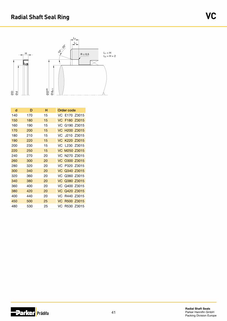
41Radial Shaft Seals Parker Hannifin GmbHPacking Division Europe
L1
L2
H 10° -
20°
R ≤ 0,5
Ø D
H8
Ø d
h11
Ø D
Ø d
L1 = HL2 = H + 2
d D H Order code
140 170 15 VC E170 Z3015
150 180 15 VC F180 Z3015
160 190 15 VC G190 Z3015
170 200 15 VC H200 Z3015
180 210 15 VC J210 Z3015
190 220 15 VC K220 Z3015
200 230 15 VC L230 Z3015
220 250 15 VC M250 Z3015
240 270 20 VC N270 Z3015
260 300 20 VC O300 Z3015
280 320 20 VC P320 Z3015
300 340 20 VC Q340 Z3015
320 360 20 VC Q360 Z3015
340 380 20 VC Q380 Z3015
360 400 20 VC Q400 Z3015
380 420 20 VC Q420 Z3015
400 440 20 VC R440 Z3015
450 500 25 VC R500 Z3015
480 530 25 VC R530 Z3015
Radial Shaft Seal Ring VC
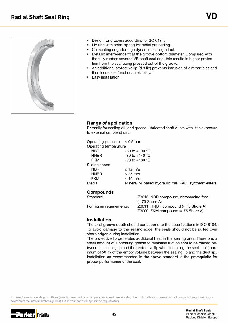
42Radial Shaft Seals Parker Hannifin GmbHPacking Division Europe
• Design for grooves according to ISO 6194.• Lip ring with spiral spring for radial preloading.• Cut sealing edge for high dynamic sealing effect.• Metallic interference fit at the groove bottom diameter. Compared with
the fully rubber-covered VB shaft seal ring, this results in higher protec-tion from the seal being pressed out of the groove.
• An additional protective lip (dirt lip) prevents intrusion of dirt particles and thus increases functional reliability.
• Easy installation.
Range of applicationPrimarily for sealing oil- and grease-lubricated shaft ducts with little exposure to external (ambient) dirt.
Operating pressure ≤ 0.5 barOperating temperature NBR -30 to +100 °C HNBR -30 to +140 °C FKM -20 to +180 °CSliding speed NBR ≤ 12 m/s HNBR ≤ 25 m/s FKM ≤ 40 m/sMedia Mineral oil based hydraulic oils, PAO, synthetic esters
CompoundsStandard: Z3015, NBR compound, nitrosamine-free (≈ 75 Shore A)For higher requirements: Z3011, HNBR compound (≈ 75 Shore A) Z3000, FKM compound (≈ 75 Shore A)
InstallationThe axial groove depth should correspond to the specifications in ISO 6194. To avoid damage to the sealing edge, the seals should not be pulled over sharp edges during installation.The protective lip generates additional heat in the sealing area. Therefore, a small amount of lubricating grease to minimise friction should be placed be-tween the sealing lip and the protective lip when installing the seal seal (max-imum of 50 % of the empty volume between the sealing lip and the dust lip). Installation as recommended in the above standard is the prerequisite for proper performance of the seal.
In case of special operating conditions (specific pressure loads, temperature, speed, use in water, HFA, HFB fluids etc.), please contact our consultancy service for a selection of the material and design best suiting your particular application requirements.
Radial Shaft Seal Ring VD
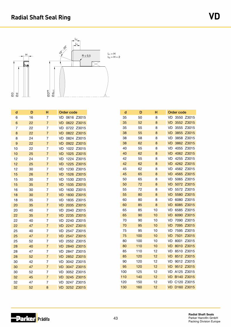
43Radial Shaft Seals Parker Hannifin GmbHPacking Division Europe
L1
L2
10° -
20°
R ≤ 0,5
Ø D
H8
Ø d
h11
Ø D
Ø d
H L1 = HL2 = H + 2
d D H Order code
35 50 8 VD 3550 Z3015
35 52 8 VD 3552 Z3015
35 55 8 VD 3555 Z3015
38 55 8 VD 3855 Z3015
38 58 8 VD 3858 Z3015
38 62 8 VD 3862 Z3015
40 55 8 VD 4055 Z3015
40 62 8 VD 4062 Z3015
42 55 8 VD 4255 Z3015
42 62 8 VD 4262 Z3015
45 62 8 VD 4562 Z3015
45 65 8 VD 4565 Z3015
50 65 8 VD 5065 Z3015
50 72 8 VD 5072 Z3015
55 72 8 VD 5572 Z3015
55 80 8 VD 5580 Z3015
60 80 8 VD 6080 Z3015
60 85 8 VD 6085 Z3015
65 85 10 VD 6585 Z3015
65 90 10 VD 6090 Z3015
70 90 10 VD 7090 Z3015
70 95 10 VD 7095 Z3015
75 95 10 VD 7595 Z3015
75 100 10 VD 7501 Z3015
80 100 10 VD 8001 Z3015
80 110 10 VD 8010 Z3015
85 110 12 VD 8510 Z3015
85 120 12 VD 8512 Z3015
90 120 12 VD 9012 Z3015
95 120 12 VD 9512 Z3015
100 125 12 VD A125 Z3015
110 140 12 VD B140 Z3015
120 150 12 VD C120 Z3015
130 160 12 VD D160 Z3015
d D H Order code
6 16 7 VD 0616 Z3015
6 22 7 VD 0622 Z3015
7 22 7 VD 0722 Z3015
8 22 7 VD 0822 Z3015
8 24 7 VD 0824 Z3015
9 22 7 VD 0922 Z3015
10 22 7 VD 1022 Z3015
10 25 7 VD 1025 Z3015
12 24 7 VD 1224 Z3015
12 25 7 VD 1225 Z3015
12 30 7 VD 1230 Z3015
15 26 7 VD 1526 Z3015
15 30 7 VD 1530 Z3015
15 35 7 VD 1535 Z3015
16 30 7 VD 1630 Z3015
18 30 7 VD 1830 Z3015
18 35 7 VD 1835 Z3015
20 35 7 VD 2035 Z3015
20 40 7 VD 2040 Z3015
22 35 7 VD 2235 Z3015
22 40 7 VD 2240 Z3015
22 47 7 VD 2247 Z3015
25 40 7 VD 2547 Z3015
25 47 7 VD 2547 Z3015
25 52 7 VD 2552 Z3015
28 40 7 VD 2840 Z3015
28 47 7 VD 2847 Z3015
28 52 7 VD 2852 Z3015
30 42 7 VD 3042 Z3015
30 47 7 VD 3047 Z3015
30 52 7 VD 3052 Z3015
32 45 7 VD 3245 Z3015
32 47 7 VD 3247 Z3015
32 52 8 VD 3252 Z3015
Radial Shaft Seal Ring VD

44Radial Shaft Seals Parker Hannifin GmbHPacking Division Europe
L1
L2
10° -
20°
R ≤ 0,5
Ø D
H8
Ø d
h11
Ø D
Ø d
H L1 = HL2 = H + 2
d D H Order code
140 170 15 VD E170 Z3015
150 180 15 VD F180 Z3015
160 190 15 VD G190 Z3015
170 200 15 VD H200 Z3015
180 210 15 VD J210 Z3015
190 220 15 VD K220 Z3015
200 230 15 VD L230 Z3015
220 250 15 VD M250 Z3015
240 270 20 VD N270 Z3015
260 300 20 VD O300 Z3015
280 320 20 VD P320 Z3015
300 340 20 VD Q340 Z3015
320 360 20 VD Q360 Z3015
340 380 20 VD Q380 Z3015
360 400 20 VD Q400 Z3015
380 420 20 VD Q420 Z3015
400 440 20 VD R440 Z3015
450 500 25 VD R500 Z3015
480 530 25 VD R530 Z3015
Radial Shaft Seal Ring VD
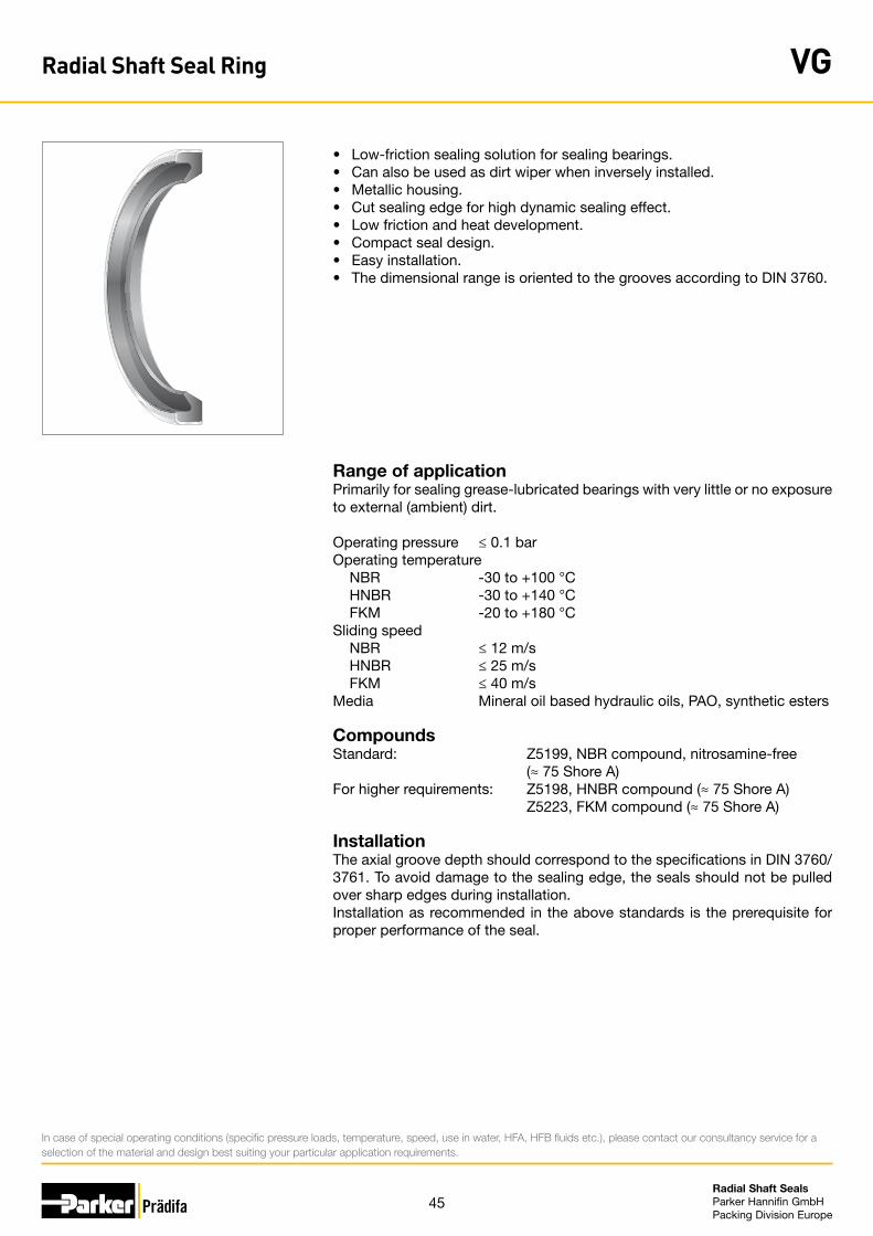
45Radial Shaft Seals Parker Hannifin GmbHPacking Division Europe
• Low-friction sealing solution for sealing bearings.• Can also be used as dirt wiper when inversely installed.• Metallic housing.• Cut sealing edge for high dynamic sealing effect.• Low friction and heat development.• Compact seal design.• Easy installation.• The dimensional range is oriented to the grooves according to DIN 3760.
Range of applicationPrimarily for sealing grease-lubricated bearings with very little or no exposure to external (ambient) dirt.
Operating pressure ≤ 0.1 barOperating temperature NBR -30 to +100 °C HNBR -30 to +140 °C FKM -20 to +180 °CSliding speed NBR ≤ 12 m/s HNBR ≤ 25 m/s FKM ≤ 40 m/sMedia Mineral oil based hydraulic oils, PAO, synthetic esters
CompoundsStandard: Z5199, NBR compound, nitrosamine-free (≈ 75 Shore A)For higher requirements: Z5198, HNBR compound (≈ 75 Shore A) Z5223, FKM compound (≈ 75 Shore A)
InstallationThe axial groove depth should correspond to the specifications in DIN 3760/3761. To avoid damage to the sealing edge, the seals should not be pulled over sharp edges during installation.Installation as recommended in the above standards is the prerequisite for proper performance of the seal.
In case of special operating conditions (specific pressure loads, temperature, speed, use in water, HFA, HFB fluids etc.), please contact our consultancy service for a selection of the material and design best suiting your particular application requirements.
Radial Shaft Seal Ring VG
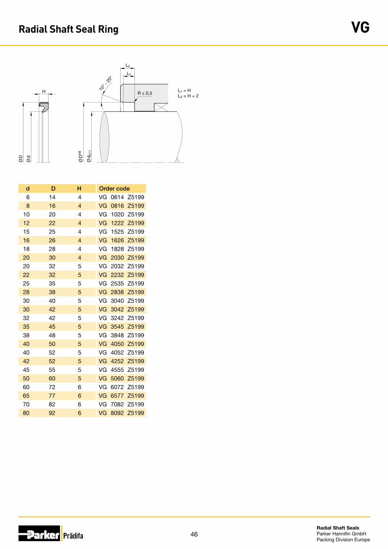
46Radial Shaft Seals Parker Hannifin GmbHPacking Division Europe
L1
L2
H 10° -
20°
R ≤ 0,5
Ø D
H8
Ø d
h11
Ø D
Ø d
L1 = HL2 = H + 2
d D H Order code
6 14 4 VG 0614 Z5199
8 16 4 VG 0816 Z5199
10 20 4 VG 1020 Z5199
12 22 4 VG 1222 Z5199
15 25 4 VG 1525 Z5199
16 26 4 VG 1626 Z5199
18 28 4 VG 1828 Z5199
20 30 4 VG 2030 Z5199
20 32 5 VG 2032 Z5199
22 32 5 VG 2232 Z5199
25 35 5 VG 2535 Z5199
28 38 5 VG 2838 Z5199
30 40 5 VG 3040 Z5199
30 42 5 VG 3042 Z5199
32 42 5 VG 3242 Z5199
35 45 5 VG 3545 Z5199
38 48 5 VG 3848 Z5199
40 50 5 VG 4050 Z5199
40 52 5 VG 4052 Z5199
42 52 5 VG 4252 Z5199
45 55 5 VG 4555 Z5199
50 60 5 VG 5060 Z5199
60 72 6 VG 6072 Z5199
65 77 6 VG 6577 Z5199
70 82 6 VG 7082 Z5199
80 92 6 VG 8092 Z5199
Radial Shaft Seal Ring VG
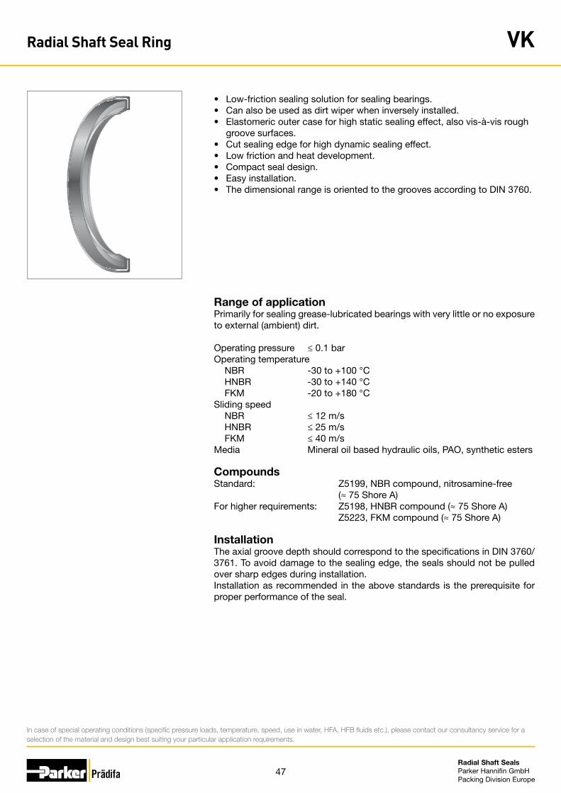
47Radial Shaft Seals Parker Hannifin GmbHPacking Division Europe
• Low-friction sealing solution for sealing bearings.• Can also be used as dirt wiper when inversely installed.• Elastomeric outer case for high static sealing effect, also vis-à-vis rough
groove surfaces. • Cut sealing edge for high dynamic sealing effect.• Low friction and heat development.• Compact seal design.• Easy installation.• The dimensional range is oriented to the grooves according to DIN 3760.
Range of applicationPrimarily for sealing grease-lubricated bearings with very little or no exposure to external (ambient) dirt.
Operating pressure ≤ 0.1 barOperating temperature NBR -30 to +100 °C HNBR -30 to +140 °C FKM -20 to +180 °CSliding speed NBR ≤ 12 m/s HNBR ≤ 25 m/s FKM ≤ 40 m/sMedia Mineral oil based hydraulic oils, PAO, synthetic esters
CompoundsStandard: Z5199, NBR compound, nitrosamine-free (≈ 75 Shore A)For higher requirements: Z5198, HNBR compound (≈ 75 Shore A) Z5223, FKM compound (≈ 75 Shore A)
InstallationThe axial groove depth should correspond to the specifications in DIN 3760/3761. To avoid damage to the sealing edge, the seals should not be pulled over sharp edges during installation.Installation as recommended in the above standards is the prerequisite for proper performance of the seal.
In case of special operating conditions (specific pressure loads, temperature, speed, use in water, HFA, HFB fluids etc.), please contact our consultancy service for a selection of the material and design best suiting your particular application requirements.
Radial Shaft Seal Ring VK
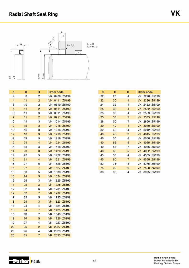
48Radial Shaft Seals Parker Hannifin GmbHPacking Division Europe
L1
L2
H 10° -
20°
R ≤ 0,5
Ø D
H8
Ø d
h11
Ø D
Ø d
L1 = HL2 = H + 2
d D H Order code
22 28 4 VK 2228 Z5199
22 30 4 VK 2230 Z5199
24 32 4 VK 2432 Z5199
25 32 4 VK 2532 Z5199
25 33 4 VK 2533 Z5199
25 35 5 VK 2535 Z5199
28 50 7 VK 2850 Z5199
30 40 4 VK 3040 Z5199
32 42 4 VK 3242 Z5199
40 45 2 VK 4045 Z5199
40 50 4 VK 4050 Z5199
40 55 5 VK 4055 Z5199
40 55 7 VK 4055 Z5199
40 62 5 VK 4062 Z5199
45 55 4 VK 4555 Z5199
45 60 7 VK 4560 Z5199
52 75 8 VK 5275 Z5199
75 90 6 VK 7590 Z5199
80 95 4 VK 8095 Z5199
d D H Order code
4 8 2 VK 0408 Z5199
4 11 2 VK 0411 Z5199
5 10 2 VK 0510 Z5199
5 11 2 VK 0511 Z5199
6 11 3 VK 0611 Z5199
7 11 2 VK 0711 Z5199
10 14 3 VK 1014 Z5199
10 15 3 VK 1015 Z5199
12 16 3 VK 1216 Z5199
12 18 3 VK 1218 Z5199
12 19 5 VK 1219 Z5199
12 24 4 VK 1224 Z5199
14 18 3 VK 1418 Z5199
14 20 3 VK 1420 Z5199
14 22 5 VK 1422 Z5199
15 21 4 VK 1521 Z5199
15 27 5 VK 1526 Z5199
15 27 7 VK 1527 Z5199
15 30 5 VK 1530 Z5199
16 24 3 VK 1624 Z5199
16 25 3 VK 1625 Z5199
17 25 3 VK 1725 Z5199
17 32 6 VK 1731 Z5199
17 32 7 VK 1732 Z5199
17 35 5 VK 1735 Z5199
18 24 3 VK 1823 Z5199
18 24 4 VK 1824 Z5199
18 24 7 VK 1425 Z5199
18 40 7 VK 1840 Z5199
19 26 5 VK 1926 Z5199
19 27 4 VK 1927 Z5199
20 26 2 VK 2027 Z5199
20 26 4 VK 2026 Z5199
20 35 7 VK 2035 Z5199
Radial Shaft Seal Ring VK
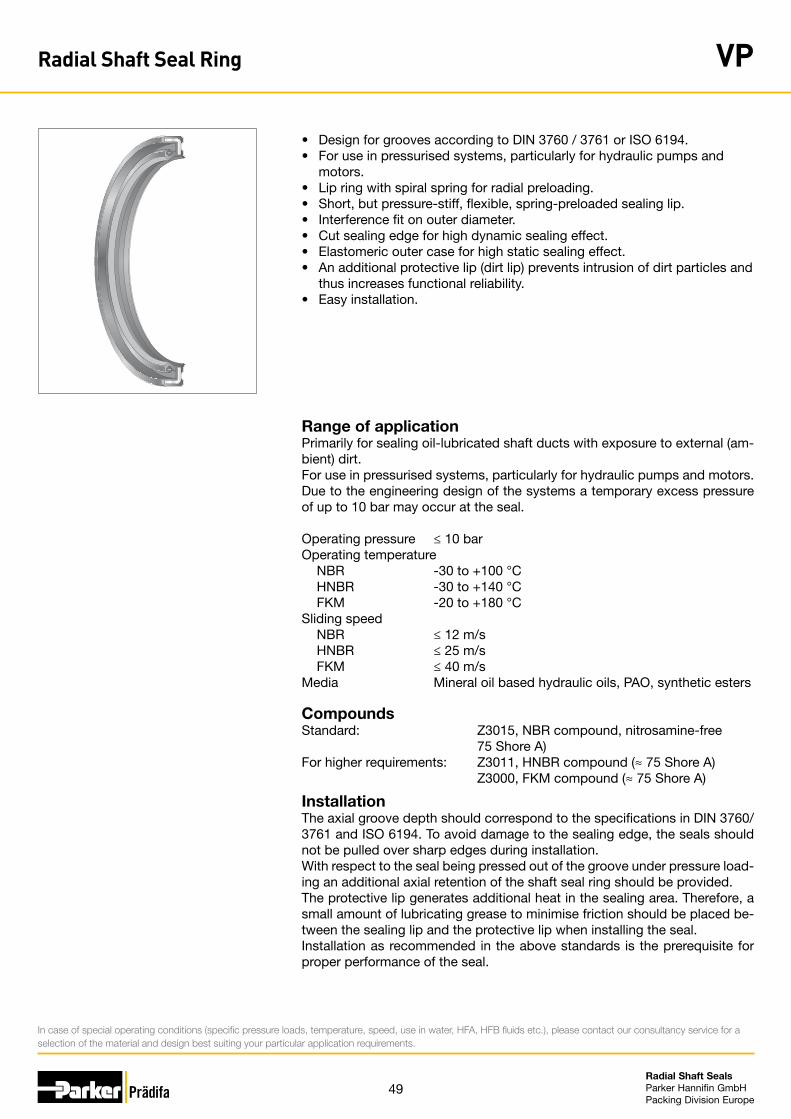
49Radial Shaft Seals Parker Hannifin GmbHPacking Division Europe
• Design for grooves according to DIN 3760 / 3761 or ISO 6194.• For use in pressurised systems, particularly for hydraulic pumps and motors.• Lip ring with spiral spring for radial preloading.• Short, but pressure-stiff, flexible, spring-preloaded sealing lip.• Interference fit on outer diameter.• Cut sealing edge for high dynamic sealing effect.• Elastomeric outer case for high static sealing effect.• An additional protective lip (dirt lip) prevents intrusion of dirt particles and
thus increases functional reliability. • Easy installation.
Range of applicationPrimarily for sealing oil-lubricated shaft ducts with exposure to external (am-bient) dirt. For use in pressurised systems, particularly for hydraulic pumps and motors. Due to the engineering design of the systems a temporary excess pressure of up to 10 bar may occur at the seal.
Operating pressure ≤ 10 barOperating temperature NBR -30 to +100 °C HNBR -30 to +140 °C FKM -20 to +180 °CSliding speed NBR ≤ 12 m/s HNBR ≤ 25 m/s FKM ≤ 40 m/sMedia Mineral oil based hydraulic oils, PAO, synthetic esters
CompoundsStandard: Z3015, NBR compound, nitrosamine-free 75 Shore A)For higher requirements: Z3011, HNBR compound (≈ 75 Shore A) Z3000, FKM compound (≈ 75 Shore A)
InstallationThe axial groove depth should correspond to the specifications in DIN 3760/3761 and ISO 6194. To avoid damage to the sealing edge, the seals should not be pulled over sharp edges during installation.With respect to the seal being pressed out of the groove under pressure load-ing an additional axial retention of the shaft seal ring should be provided.The protective lip generates additional heat in the sealing area. Therefore, a small amount of lubricating grease to minimise friction should be placed be-tween the sealing lip and the protective lip when installing the seal.Installation as recommended in the above standards is the prerequisite for proper performance of the seal.
In case of special operating conditions (specific pressure loads, temperature, speed, use in water, HFA, HFB fluids etc.), please contact our consultancy service for a selection of the material and design best suiting your particular application requirements.
Radial Shaft Seal Ring VP

50Radial Shaft Seals Parker Hannifin GmbHPacking Division Europe
L1
L2
H 10° -
20°
R ≤ 0,5
Ø D
H8
Ø d
h11
Ø D
Ø d
L1 = HL2 = H + 5
d D H Order code
25 45 6/6.6 VP 2545 Z3015
25 47 6/6.6 VP 2547 Z3015
25.4 38.1 6/6.6 VP 2538 Z3015
26 40 6/6.6 VP 2640 Z3015
27 39 6/6.6 VP 2739 Z3015
28 40 6/6.6 VP 2840 Z3015
28 42 6/6.6 VP 2842 Z3015
28 45 6/6.6 VP 2845 Z3015
30 42 6/6.6 VP 3042 Z3015
30 45 6/6.6 VP 3045 Z3015
30 50 6/6.6 VP 3050 Z3015
30 52 6/6.6 VP 3051 Z3015
30 52 7/8 VP 3052 Z3015
30 55 6/6.6 VP 3055 Z3015
30 62 6/6.6 VP 3062 Z3015
31.7 44.5 6/6.6 VP 3244 Z3015
32 45 6/6.6 VP 3245 Z3015
32 47 6/6.6 VP 3247 Z3015
32 52 6/6.6 VP 3252 Z3015
35 47 6/6.6 VP 3547 Z3015
35 50 6/6.6 VP 3550 Z3015
35 52 6/6.6 VP 3552 Z3015
35 55 6/6.6 VP 3555 Z3015
38 50 6/6.6 VP 3850 Z3015
40 52 6/6.6 VP 4052 Z3015
40 55 7/8 VP 4055 Z3015
40 60 6/6.6 VP 4060 Z3015
40 62 6/6.6 VP 4062 Z3015
40 65 6/6.6 VP 4065 Z3015
42 62 6/6.6 VP 4262 Z3015
44.45 60 7/8 VP 4445 Z3015
45 58 7/8 VP 4558 Z3015
45 60 7/8 VP 4560 Z3015
45 62 7/8 VP 4562 Z3015
d D H Order code
8 22 6/6.6 VP 0822 Z3015
10 22 6/6.6 VP 1022 Z3015
12 22 6/6.6 VP 1222 Z3015
12 24 6/6.6 VP 1224 Z3015
12 32 6/6.6 VP 1230 Z3015
14 24 6/6.6 VP 1424 Z3015
15 25 6/6.6 VP 1525 Z3015
15 30 6/6.6 VP 1530 Z3015
15 32 6/6.6 VP 1532 Z3015
15 35 6/6.6 VP 1535 Z3015
16 26 6/6.6 VP 1626 Z3015
16 32 6/6.6 VP 1632 Z3015
16 40 6/6.6 VP 1640 Z3015
17 30 6/6.6 VP 1729 Z3015
17 30 7/8 VP 1730 Z3015
17 32 7/8 VP 1732 Z3015
17 35 6/6.6 VP 1735 Z3015
17 40 6/6.6 VP 1740 Z3015
18 30 7/8 VP 1830 Z3015
18 32 6/6.6 VP 1832 Z3015
18 40 6/6.6 VP 1840 Z3015
19 31.66 6/6.6 VP 1931 Z3015
19 35 6/6.6 VP 1935 Z3015
20 30 6/6.6 VP 2030 Z3015
20 32 6/6.6 VP 2032 Z3015
20 35 6/6.6 VP 2035 Z3015
20 40 6/6.6 VP 2040 Z3015
22 32 6/6.6 VP 2232 Z3015
22 35 6/6.6 VP 2235 Z3015
24 40 6/6.6 VP 2440 Z3015
25 35 6/6.6 VP 2535 Z3015
25 37 6/6.6 VP 2537 Z3015
25 40 6/6.6 VP 2540 Z3015
25 42 6/6.6 VP 2542 Z3015
Radial Shaft Seal Ring VP

51Radial Shaft Seals Parker Hannifin GmbHPacking Division Europe
L1
L2
H 10° -
20°
R ≤ 0,5
Ø D
H8
Ø d
h11
Ø D
Ø d
L1 = HL2 = H + 5
d D H Order code
85 110 7/8 VP 8511 Z3015
85 120 7/8 VP 8512 Z3015
90 110 7/8 VP 9010 Z3015
90 115 7/8 VP 9011 Z3015
90 120 7/8 VP 9012 Z3015
95 120 7/8 VP 9512 Z3015
100 120 7/8 VP A120 Z3015
100 125 7/8 VP A125 Z3015
105 130 7/8 VP A130 Z3015
110 125 7/8 VP B125 Z3015
110 130 7/8 VP B130 Z3015
110 135 7/8 VP B135 Z3015
110 140 7/8 VP B140 Z3015
120 135 7/8 VP C135 Z3015
120 140 7/8 VP C140 Z3015
120 145 7/8 VP C145 Z3015
120 150 7/8 VP C150 Z3015
130 145 7/8 VP D145 Z3015
130 150 7/8 VP D150 Z3015
130 155 7/8 VP D155 Z3015
140 155 7/8 VP E155 Z3015
140 160 7/8 VP E160 Z3015
140 165 7/8 VP E165 Z3015
150 165 7/8 VP F165 Z3015
150 170 7/8 VP F170 Z3015
150 180 7/8 VP F180 Z3015
160 180 7/8 VP G180 Z3015
160 185 7/8 VP G185 Z3015
170 190 7/8 VP H190 Z3015
170 200 7/8 VP H200 Z3015
180 200 7/8 VP J200 Z3015
180 210 8.5/9.5 VP J210 Z3015
190 210 7/8 VP K210 Z3015
200 210 7/8 VP L210 Z3015
d D H Order code
45 65 7/8 VP 4565 Z3015
45 68 7/8 VP 4568 Z3015
48 72 7/8 VP 4872 Z3015
50 62 7/8 VP 5062 Z3015
50 65 7/8 VP 5065 Z3015
50 70 7/8 VP 5070 Z3015
50 72 7/8 VP 5072 Z3015
50 75 7/8 VP 5075 Z3015
50 80 7/8 VP 5080 Z3015
52 68 7/8 VP 5268 Z3015
52 72 7/8 VP 5272 Z3015
55 70 7/8 VP 5570 Z3015
55 72 7/8 VP 5572 Z3015
55 75 7/8 VP 5575 Z3015
55 90 7/8 VP 5590 Z3015
60 72 7/8 VP 6072 Z3015
60 75 7/8 VP 6075 Z3015
60 80 7/8 VP 6080 Z3015
60 85 7/8 VP 6085 Z3015
60 90 7/8 VP 6090 Z3015
62 85 7/8 VP 6285 Z3015
65 80 7/8 VP 6580 Z3015
65 85 7/8 VP 6585 Z3015
65 90 7/8 VP 6590 Z3015
65 95 7/8 VP 6595 Z3015
70 82 7/8 VP 7082 Z3015
70 85 7/8 VP 7085 Z3015
70 90 7/8 VP 7090 Z3015
75 90 7/8 VP 7590 Z3015
75 100 7/8 VP 7510 Z3015
80 95 7/8 VP 8095 Z3015
80 100 7/8 VP 8010 Z3015
80 105 7/8 VP 8011 Z3015
85 105 7/8 VP 8510 Z3015
Radial Shaft Seal Ring VP
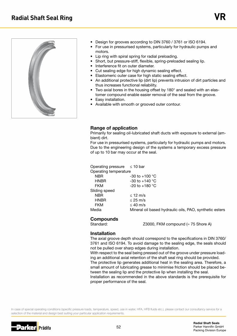
52Radial Shaft Seals Parker Hannifin GmbHPacking Division Europe
• Design for grooves according to DIN 3760 / 3761 or ISO 6194.• For use in pressurised systems, particularly for hydraulic pumps and motors.• Lip ring with spiral spring for radial preloading.• Short, but pressure-stiff, flexible, spring-preloaded sealing lip.• Interference fit on outer diameter.• Cut sealing edge for high dynamic sealing effect.• Elastomeric outer case for high static sealing effect.• An additional protective lip (dirt lip) prevents intrusion of dirt particles and
thus increases functional reliability. • Two axial bores in the housing offset by 180° and sealed with an elas-
tomer compound enable easier removal of the seal from the groove.• Easy installation.• Available with smooth or grooved outer contour.
Range of applicationPrimarily for sealing oil-lubricated shaft ducts with exposure to external (am-bient) dirt. For use in pressurised systems, particularly for hydraulic pumps and motors. Due to the engineering design of the systems a temporary excess pressure of up to 10 bar may occur at the seal.
Operating pressure ≤ 10 barOperating temperature NBR -30 to +100 °C HNBR -30 to +140 °C FKM -20 to +180 °CSliding speed NBR ≤ 12 m/s HNBR ≤ 25 m/s FKM ≤ 40 m/sMedia Mineral oil based hydraulic oils, PAO, synthetic esters
CompoundsStandard: Z3000, FKM compound (≈ 75 Shore A)
InstallationThe axial groove depth should correspond to the specifications in DIN 3760/3761 and ISO 6194. To avoid damage to the sealing edge, the seals should not be pulled over sharp edges during installation.With respect to the seal being pressed out of the groove under pressure load-ing an additional axial retention of the shaft seal ring should be provided.The protective lip generates additional heat in the sealing area. Therefore, a small amount of lubricating grease to minimise friction should be placed be-tween the sealing lip and the protective lip when installing the seal.Installation as recommended in the above standards is the prerequisite for proper performance of the seal.
In case of special operating conditions (specific pressure loads, temperature, speed, use in water, HFA, HFB fluids etc.), please contact our consultancy service for a selection of the material and design best suiting your particular application requirements.
Radial Shaft Seal Ring VR
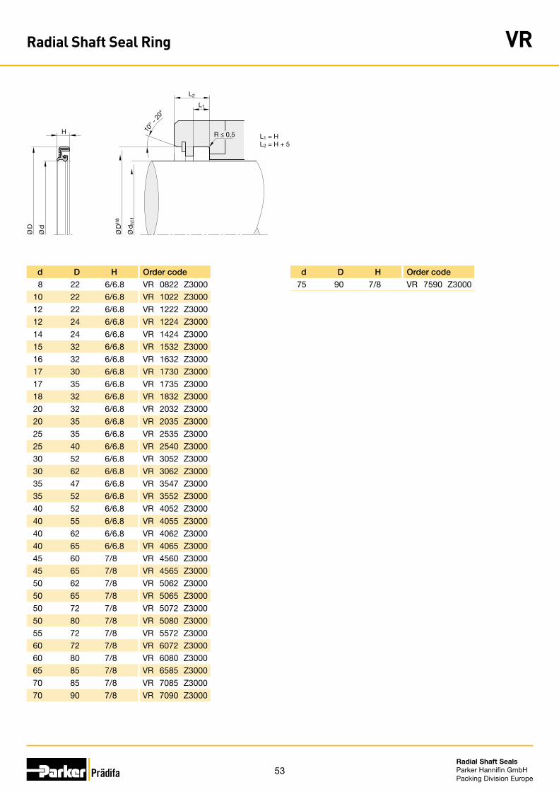
53Radial Shaft Seals Parker Hannifin GmbHPacking Division Europe
L1
L2
H 10° -
20°
R ≤ 0,5
Ø D
H8
Ø d
h11
Ø D
Ø d
L1 = HL2 = H + 5
d D H Order code
8 22 6/6.8 VR 0822 Z3000
10 22 6/6.8 VR 1022 Z3000
12 22 6/6.8 VR 1222 Z3000
12 24 6/6.8 VR 1224 Z3000
14 24 6/6.8 VR 1424 Z3000
15 32 6/6.8 VR 1532 Z3000
16 32 6/6.8 VR 1632 Z3000
17 30 6/6.8 VR 1730 Z3000
17 35 6/6.8 VR 1735 Z3000
18 32 6/6.8 VR 1832 Z3000
20 32 6/6.8 VR 2032 Z3000
20 35 6/6.8 VR 2035 Z3000
25 35 6/6.8 VR 2535 Z3000
25 40 6/6.8 VR 2540 Z3000
30 52 6/6.8 VR 3052 Z3000
30 62 6/6.8 VR 3062 Z3000
35 47 6/6.8 VR 3547 Z3000
35 52 6/6.8 VR 3552 Z3000
40 52 6/6.8 VR 4052 Z3000
40 55 6/6.8 VR 4055 Z3000
40 62 6/6.8 VR 4062 Z3000
40 65 6/6.8 VR 4065 Z3000
45 60 7/8 VR 4560 Z3000
45 65 7/8 VR 4565 Z3000
50 62 7/8 VR 5062 Z3000
50 65 7/8 VR 5065 Z3000
50 72 7/8 VR 5072 Z3000
50 80 7/8 VR 5080 Z3000
55 72 7/8 VR 5572 Z3000
60 72 7/8 VR 6072 Z3000
60 80 7/8 VR 6080 Z3000
65 85 7/8 VR 6585 Z3000
70 85 7/8 VR 7085 Z3000
70 90 7/8 VR 7090 Z3000
d D H Order code
75 90 7/8 VR 7590 Z3000
Radial Shaft Seal Ring VR
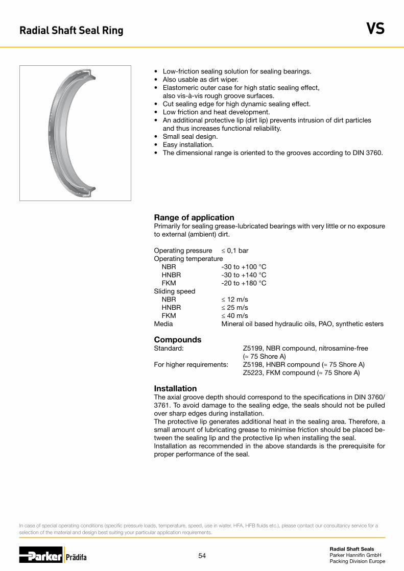
54Radial Shaft Seals Parker Hannifin GmbHPacking Division Europe
• Low-friction sealing solution for sealing bearings.• Also usable as dirt wiper.• Elastomeric outer case for high static sealing effect, also vis-à-vis rough groove surfaces. • Cut sealing edge for high dynamic sealing effect.• Low friction and heat development.• An additional protective lip (dirt lip) prevents intrusion of dirt particles and thus increases functional reliability. • Small seal design.• Easy installation.• The dimensional range is oriented to the grooves according to DIN 3760.
Range of applicationPrimarily for sealing grease-lubricated bearings with very little or no exposure to external (ambient) dirt.
Operating pressure ≤ 0,1 barOperating temperature NBR -30 to +100 °C HNBR -30 to +140 °C FKM -20 to +180 °CSliding speed NBR ≤ 12 m/s HNBR ≤ 25 m/s FKM ≤ 40 m/sMedia Mineral oil based hydraulic oils, PAO, synthetic esters
CompoundsStandard: Z5199, NBR compound, nitrosamine-free (≈ 75 Shore A)For higher requirements: Z5198, HNBR compound (≈ 75 Shore A) Z5223, FKM compound (≈ 75 Shore A)
InstallationThe axial groove depth should correspond to the specifications in DIN 3760/3761. To avoid damage to the sealing edge, the seals should not be pulled over sharp edges during installation.The protective lip generates additional heat in the sealing area. Therefore, a small amount of lubricating grease to minimise friction should be placed be-tween the sealing lip and the protective lip when installing the seal.Installation as recommended in the above standards is the prerequisite for proper performance of the seal.
In case of special operating conditions (specific pressure loads, temperature, speed, use in water, HFA, HFB fluids etc.), please contact our consultancy service for a selection of the material and design best suiting your particular application requirements.
Radial Shaft Seal Ring VS
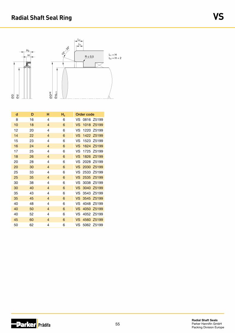
55Radial Shaft Seals Parker Hannifin GmbHPacking Division Europe
L1
L2
H
H2
L1 = HL2 = H + 2
10° -
20°
R ≤ 0,5
Ø D
H8
Ø d
h11
Ø D
Ø d
d D H H2 Order code
8 16 4 6 VS 0816 Z5199
10 18 4 6 VS 1018 Z5199
12 20 4 6 VS 1220 Z5199
14 22 4 6 VS 1422 Z5199
15 23 4 6 VS 1523 Z5199
16 24 4 6 VS 1624 Z5199
17 25 4 6 VS 1725 Z5199
18 26 4 6 VS 1826 Z5199
20 28 4 6 VS 2028 Z5199
20 30 4 6 VS 2030 Z5199
25 33 4 6 VS 2533 Z5199
25 35 4 6 VS 2535 Z5199
30 38 4 6 VS 3038 Z5199
30 40 4 6 VS 3040 Z5199
35 43 4 6 VS 3543 Z5199
35 45 4 6 VS 3545 Z5199
40 48 4 6 VS 4048 Z5199
40 50 4 6 VS 4050 Z5199
40 52 4 6 VS 4052 Z5199
45 60 4 6 VS 4560 Z5199
50 62 4 6 VS 5062 Z5199
Radial Shaft Seal Ring VS
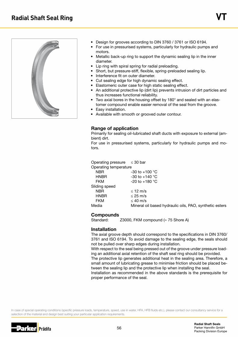
56Radial Shaft Seals Parker Hannifin GmbHPacking Division Europe
• Design for grooves according to DIN 3760 / 3761 or ISO 6194.• For use in pressurised systems, particularly for hydraulic pumps and motors.• Metallic back-up ring to support the dynamic sealing lip in the inner diameter.• Lip ring with spiral spring for radial preloading.• Short, but pressure-stiff, flexible, spring-preloaded sealing lip.• Interference fit on outer diameter.• Cut sealing edge for high dynamic sealing effect.• Elastomeric outer case for high static sealing effect.• An additional protective lip (dirt lip) prevents intrusion of dirt particles and
thus increases functional reliability. • Two axial bores in the housing offset by 180° and sealed with an elas-
tomer compound enable easier removal of the seal from the groove.• Easy installation.• Available with smooth or grooved outer contour.
Range of applicationPrimarily for sealing oil-lubricated shaft ducts with exposure to external (am-bient) dirt. For use in pressurised systems, particularly for hydraulic pumps and mo-tors.
Operating pressure ≤ 30 barOperating temperature NBR -30 to +100 °C HNBR -30 to +140 °C FKM -20 to +180 °CSliding speed NBR ≤ 12 m/s HNBR ≤ 25 m/s FKM ≤ 40 m/sMedia Mineral oil based hydraulic oils, PAO, synthetic esters
CompoundsStandard: Z3000, FKM compound (≈ 75 Shore A)
InstallationThe axial groove depth should correspond to the specifications in DIN 3760/3761 and ISO 6194. To avoid damage to the sealing edge, the seals should not be pulled over sharp edges during installation.With respect to the seal being pressed out of the groove under pressure load-ing an additional axial retention of the shaft seal ring should be provided.The protective lip generates additional heat in the sealing area. Therefore, a small amount of lubricating grease to minimise friction should be placed be-tween the sealing lip and the protective lip when installing the seal.Installation as recommended in the above standards is the prerequisite for proper performance of the seal.
In case of special operating conditions (specific pressure loads, temperature, speed, use in water, HFA, HFB fluids etc.), please contact our consultancy service for a selection of the material and design best suiting your particular application requirements.
Radial Shaft Seal Ring VT
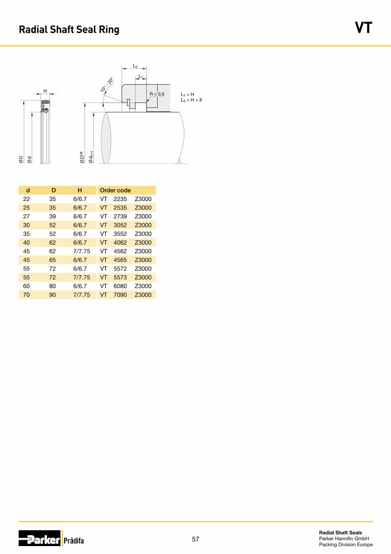
57Radial Shaft Seals Parker Hannifin GmbHPacking Division Europe
d D H Order code
22 35 6/6.7 VT 2235 Z3000
25 35 6/6.7 VT 2535 Z3000
27 39 6/6.7 VT 2739 Z3000
30 52 6/6.7 VT 3052 Z3000
35 52 6/6.7 VT 3552 Z3000
40 62 6/6.7 VT 4062 Z3000
45 62 7/7.75 VT 4562 Z3000
45 65 6/6.7 VT 4565 Z3000
55 72 6/6.7 VT 5572 Z3000
55 72 7/7.75 VT 5573 Z3000
60 80 6/6.7 VT 6080 Z3000
70 90 7/7.75 VT 7090 Z3000
L1
L2
H 10° -
20°
R ≤ 0,5
Ø D
H8
Ø d
h11
Ø d
Ø D
L1 = HL2 = H + 8
Radial Shaft Seal Ring VT
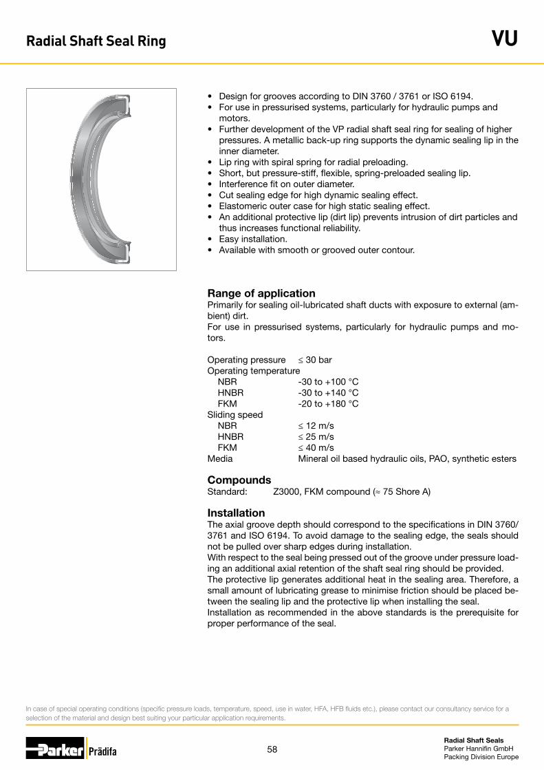
58Radial Shaft Seals Parker Hannifin GmbHPacking Division Europe
• Design for grooves according to DIN 3760 / 3761 or ISO 6194.• For use in pressurised systems, particularly for hydraulic pumps and motors.• Further development of the VP radial shaft seal ring for sealing of higher
pressures. A metallic back-up ring supports the dynamic sealing lip in the inner diameter.
• Lip ring with spiral spring for radial preloading.• Short, but pressure-stiff, flexible, spring-preloaded sealing lip.• Interference fit on outer diameter.• Cut sealing edge for high dynamic sealing effect.• Elastomeric outer case for high static sealing effect.• An additional protective lip (dirt lip) prevents intrusion of dirt particles and
thus increases functional reliability. • Easy installation.• Available with smooth or grooved outer contour.
Range of applicationPrimarily for sealing oil-lubricated shaft ducts with exposure to external (am-bient) dirt. For use in pressurised systems, particularly for hydraulic pumps and mo-tors.
Operating pressure ≤ 30 barOperating temperature NBR -30 to +100 °C HNBR -30 to +140 °C FKM -20 to +180 °CSliding speed NBR ≤ 12 m/s HNBR ≤ 25 m/s FKM ≤ 40 m/sMedia Mineral oil based hydraulic oils, PAO, synthetic esters
CompoundsStandard: Z3000, FKM compound (≈ 75 Shore A)
InstallationThe axial groove depth should correspond to the specifications in DIN 3760/3761 and ISO 6194. To avoid damage to the sealing edge, the seals should not be pulled over sharp edges during installation.With respect to the seal being pressed out of the groove under pressure load-ing an additional axial retention of the shaft seal ring should be provided.The protective lip generates additional heat in the sealing area. Therefore, a small amount of lubricating grease to minimise friction should be placed be-tween the sealing lip and the protective lip when installing the seal.Installation as recommended in the above standards is the prerequisite for proper performance of the seal.
In case of special operating conditions (specific pressure loads, temperature, speed, use in water, HFA, HFB fluids etc.), please contact our consultancy service for a selection of the material and design best suiting your particular application requirements.
Radial Shaft Seal Ring VU
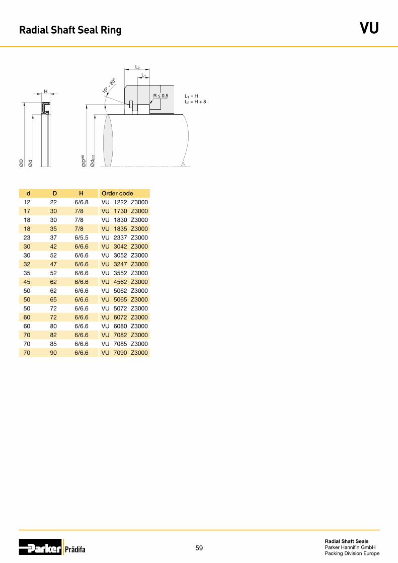
59Radial Shaft Seals Parker Hannifin GmbHPacking Division Europe
L1
L2
H 10° -
20°
Ø D
H8
Ø d
h11
Ø d
R ≤ 0,5
Ø D
L1 = HL2 = H + 8
d D H Order code
12 22 6/6.8 VU 1222 Z3000
17 30 7/8 VU 1730 Z3000
18 30 7/8 VU 1830 Z3000
18 35 7/8 VU 1835 Z3000
23 37 6/5.5 VU 2337 Z3000
30 42 6/6.6 VU 3042 Z3000
30 52 6/6.6 VU 3052 Z3000
32 47 6/6.6 VU 3247 Z3000
35 52 6/6.6 VU 3552 Z3000
45 62 6/6.6 VU 4562 Z3000
50 62 6/6.6 VU 5062 Z3000
50 65 6/6.6 VU 5065 Z3000
50 72 6/6.6 VU 5072 Z3000
60 72 6/6.6 VU 6072 Z3000
60 80 6/6.6 VU 6080 Z3000
70 82 6/6.6 VU 7082 Z3000
70 85 6/6.6 VU 7085 Z3000
70 90 6/6.6 VU 7090 Z3000
Radial Shaft Seal Ring VU
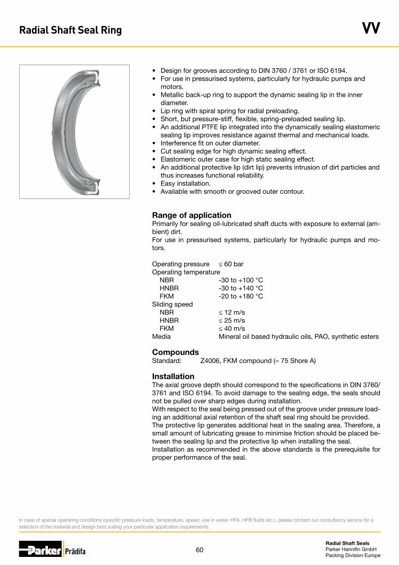
60Radial Shaft Seals Parker Hannifin GmbHPacking Division Europe
• Design for grooves according to DIN 3760 / 3761 or ISO 6194.• For use in pressurised systems, particularly for hydraulic pumps and motors.• Metallic back-up ring to support the dynamic sealing lip in the inner diameter.• Lip ring with spiral spring for radial preloading.• Short, but pressure-stiff, flexible, spring-preloaded sealing lip.• An additional PTFE lip integrated into the dynamically sealing elastomeric
sealing lip improves resistance against thermal and mechanical loads. • Interference fit on outer diameter.• Cut sealing edge for high dynamic sealing effect.• Elastomeric outer case for high static sealing effect.• An additional protective lip (dirt lip) prevents intrusion of dirt particles and
thus increases functional reliability. • Easy installation.• Available with smooth or grooved outer contour.
Range of applicationPrimarily for sealing oil-lubricated shaft ducts with exposure to external (am-bient) dirt. For use in pressurised systems, particularly for hydraulic pumps and mo-tors.
Operating pressure ≤ 60 barOperating temperature NBR -30 to +100 °C HNBR -30 to +140 °C FKM -20 to +180 °CSliding speed NBR ≤ 12 m/s HNBR ≤ 25 m/s FKM ≤ 40 m/sMedia Mineral oil based hydraulic oils, PAO, synthetic esters
CompoundsStandard: Z4006, FKM compound (≈ 75 Shore A)
InstallationThe axial groove depth should correspond to the specifications in DIN 3760/3761 and ISO 6194. To avoid damage to the sealing edge, the seals should not be pulled over sharp edges during installation.With respect to the seal being pressed out of the groove under pressure load-ing an additional axial retention of the shaft seal ring should be provided.The protective lip generates additional heat in the sealing area. Therefore, a small amount of lubricating grease to minimise friction should be placed be-tween the sealing lip and the protective lip when installing the seal.Installation as recommended in the above standards is the prerequisite for proper performance of the seal.
In case of special operating conditions (specific pressure loads, temperature, speed, use in water, HFA, HFB fluids etc.), please contact our consultancy service for a selection of the material and design best suiting your particular application requirements.
Radial Shaft Seal Ring VV
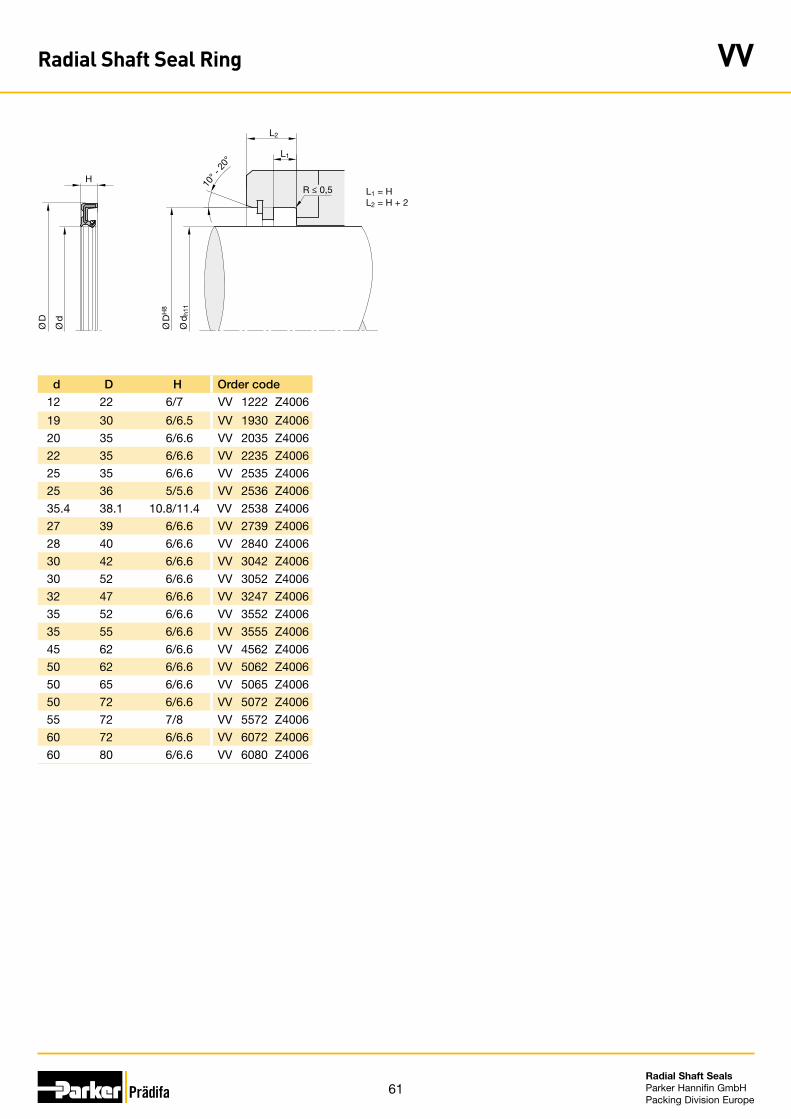
61Radial Shaft Seals Parker Hannifin GmbHPacking Division Europe
d D H Order code
12 22 6/7 VV 1222 Z4006
19 30 6/6.5 VV 1930 Z4006
20 35 6/6.6 VV 2035 Z4006
22 35 6/6.6 VV 2235 Z4006
25 35 6/6.6 VV 2535 Z4006
25 36 5/5.6 VV 2536 Z4006
35.4 38.1 10.8/11.4 VV 2538 Z4006
27 39 6/6.6 VV 2739 Z4006
28 40 6/6.6 VV 2840 Z4006
30 42 6/6.6 VV 3042 Z4006
30 52 6/6.6 VV 3052 Z4006
32 47 6/6.6 VV 3247 Z4006
35 52 6/6.6 VV 3552 Z4006
35 55 6/6.6 VV 3555 Z4006
45 62 6/6.6 VV 4562 Z4006
50 62 6/6.6 VV 5062 Z4006
50 65 6/6.6 VV 5065 Z4006
50 72 6/6.6 VV 5072 Z4006
55 72 7/8 VV 5572 Z4006
60 72 6/6.6 VV 6072 Z4006
60 80 6/6.6 VV 6080 Z4006
H
Ø d
L1
L2
10° -
20°
R ≤ 0,5
Ø D
H8
Ø d
h11
Ø D
L1 = HL2 = H + 2
Radial Shaft Seal Ring VV
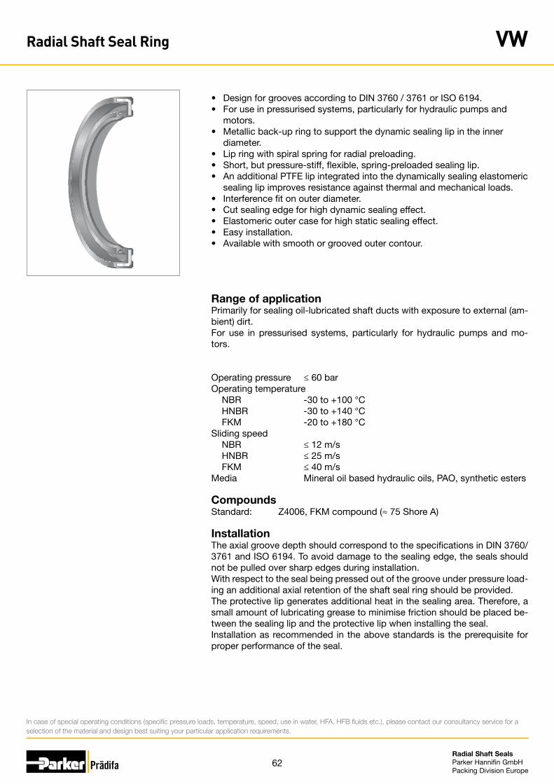
62Radial Shaft Seals Parker Hannifin GmbHPacking Division Europe
• Design for grooves according to DIN 3760 / 3761 or ISO 6194.• For use in pressurised systems, particularly for hydraulic pumps and motors.• Metallic back-up ring to support the dynamic sealing lip in the inner diameter.• Lip ring with spiral spring for radial preloading.• Short, but pressure-stiff, flexible, spring-preloaded sealing lip.• An additional PTFE lip integrated into the dynamically sealing elastomeric
sealing lip improves resistance against thermal and mechanical loads. • Interference fit on outer diameter.• Cut sealing edge for high dynamic sealing effect.• Elastomeric outer case for high static sealing effect.• Easy installation.• Available with smooth or grooved outer contour.
Range of applicationPrimarily for sealing oil-lubricated shaft ducts with exposure to external (am-bient) dirt. For use in pressurised systems, particularly for hydraulic pumps and mo-tors.
Operating pressure ≤ 60 barOperating temperature NBR -30 to +100 °C HNBR -30 to +140 °C FKM -20 to +180 °CSliding speed NBR ≤ 12 m/s HNBR ≤ 25 m/s FKM ≤ 40 m/sMedia Mineral oil based hydraulic oils, PAO, synthetic esters
CompoundsStandard: Z4006, FKM compound (≈ 75 Shore A)
InstallationThe axial groove depth should correspond to the specifications in DIN 3760/3761 and ISO 6194. To avoid damage to the sealing edge, the seals should not be pulled over sharp edges during installation.With respect to the seal being pressed out of the groove under pressure load-ing an additional axial retention of the shaft seal ring should be provided.The protective lip generates additional heat in the sealing area. Therefore, a small amount of lubricating grease to minimise friction should be placed be-tween the sealing lip and the protective lip when installing the seal.Installation as recommended in the above standards is the prerequisite for proper performance of the seal.
In case of special operating conditions (specific pressure loads, temperature, speed, use in water, HFA, HFB fluids etc.), please contact our consultancy service for a selection of the material and design best suiting your particular application requirements.
Radial Shaft Seal Ring VW
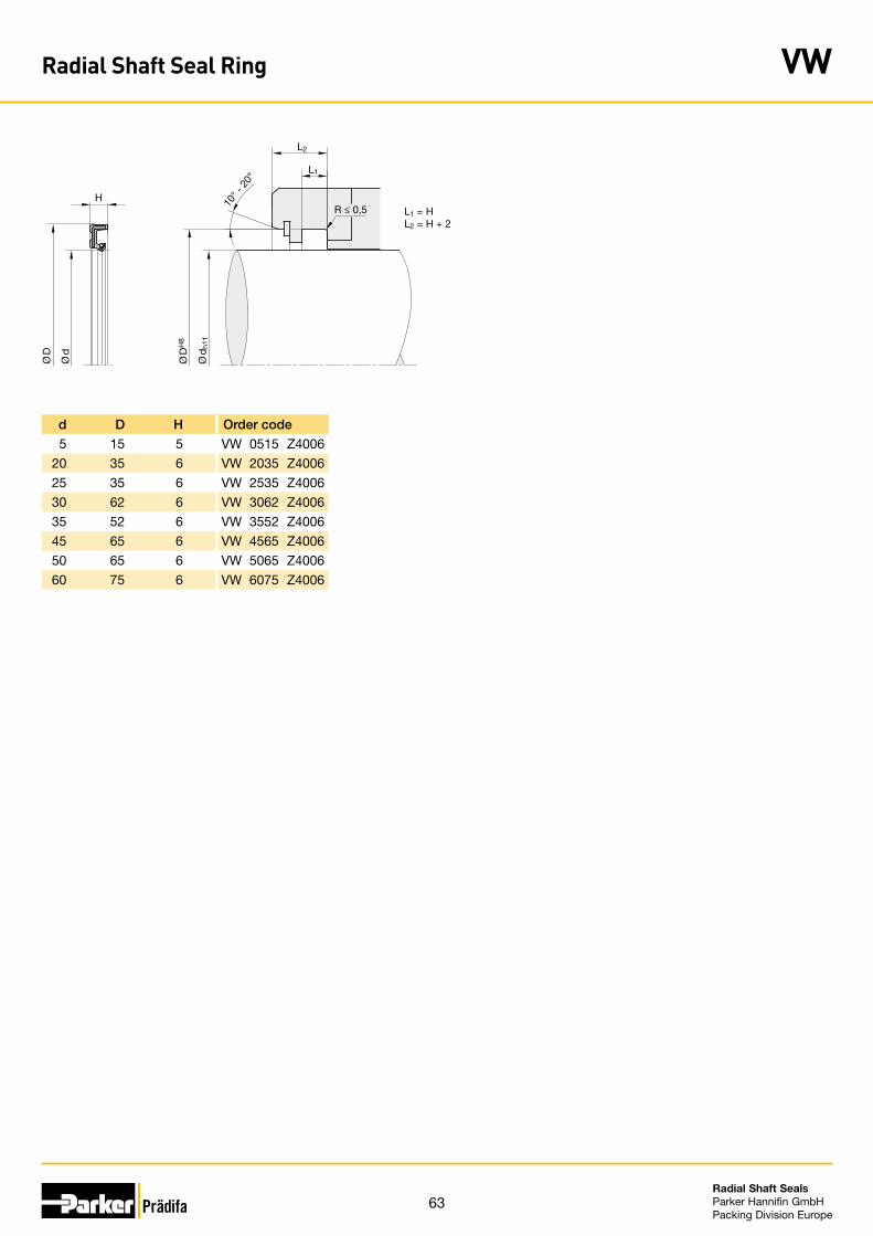
63Radial Shaft Seals Parker Hannifin GmbHPacking Division Europe
d D H Order code
5 15 5 VW 0515 Z4006
20 35 6 VW 2035 Z4006
25 35 6 VW 2535 Z4006
30 62 6 VW 3062 Z4006
35 52 6 VW 3552 Z4006
45 65 6 VW 4565 Z4006
50 65 6 VW 5065 Z4006
60 75 6 VW 6075 Z4006
Ø d
H
L1
L2
10° -
20°
R ≤ 0,5
Ø D
H8
Ø d
h11
Ø D
L1 = HL2 = H + 2
Radial Shaft Seal Ring VW

64Radial Shaft Seals Parker Hannifin GmbHPacking Division Europe
Notice

65Radial Shaft Seals Parker Hannifin GmbHPacking Division Europe
Notice

66Radial Shaft Seals Parker Hannifin GmbHPacking Division Europe
Notice


Sales Offices Worldwide
Parker Hannifin GmbHPacking Division Europe P.O. Box 164174306 Bietigheim-Bissingen · GermanyTel. +49 (0) 7142 351-0 · Fax +49 (0) 7142 351-293www.parker.com/packing-europee-mail: [email protected]
PDE 3357 GB ∙ 07/2010© 2010 Parker Hannifin Corporation · Subject to change
AE – UAE, Dubai Tel: +971 4 8127100 [email protected]
AR – Argentina, Buenos Aires Tel: +54 3327 44 4129
AT – Austria Kurt Koller, Wiener NeudorfTel: +43 22 36 6 22 08/9
AU – Australia, Castle Hill Tel: +61 2 9634 7777
AZ – Azerbaijan, Baku Tel: +994 50 2233 458 [email protected]
BE – Belgium, BoomTel: +32 3 880 81 50
BR – Brazil, Sao Paulo / SPTel: +55 11 39 15 8500
BY – Belarus, Minsk Tel: +375 17 209 9399 [email protected]
CA – Canada, Milton, Ontario Tel: +1 905 693 3000
CH – Switzerland, Etoy Tel: +41 21 821 8700 [email protected]
CN – China, Shanghai Tel: +86 21 64 45 93 39
CZ – Czech Republic,Klecany Tel: +420 284 083 111 [email protected]
DE – Germany,Bietigheim-BissingenTel: +49 7142 351 0
DK – Denmark, EspergaerdeTel: +45 49 12 17 00
ES – Spain, Madrid Tel: +34 91 6 75 73 00
ES – Spain, Barcelona Tel: +34 93 6 35 51 73
FI – FinlandTiivistekeskus Oy, VantaaTel: +358 20 76 51 70
FR – France, Annemasse-CédexTel: +33 4 50 87 80 80
GR – GreeceK Stamatiadis - E. Amplianitis S.A., AthenTel: +30 10 5 15 11 11
GR – GreeceKE.MH.S.S.A. Arvanitozissi & Co.E.E., AthenTel: +30 10 3 42 37 77
HK – Hong Kong Tel: +852 2428 8008
HU – Hungary, Budapest Tel: +36 1 220 4155 [email protected]
IL – IsraelAZMA Co. Ltd., Tel-AvivTel: +972 3 5 61 73 34
IN – India, Mumbai Tel: +91 22 6513 7081-85
IT – Italy, Corsico (MI) Tel: +39 02 45 19 21 [email protected]
JP – Japan, TokyoTel: +81 3 6408 3901
KR – Korea, SeoulTel: +82 2 559 0400
KZ – Kazakhstan, Almaty Tel: +7 7272 505 800 [email protected]
L – Luxembourg, Friederich-Hydropart S.A.R.L., SchifflangeTel: +352 54 52 44
LV – Latvia, Riga Tel: +371 6 745 2601 [email protected]
MX – Mexico, Apodaca Tel: +52 81 8156 6000
MY – Malaysia, Subang Jaya Tel: +60 3 5638 1476
NL – Netherlands, Oldenzaal Tel: +31 541 585 [email protected]
NL – NetherlandsB. V. Profiltra, AlmereTe: +31 36 53 2 42 28
NO – NorwayOtto Olsen A/S, LillestromTel: +47 6 3 89 08 00
NZ – New Zealand, Mt Wellington Tel: +64 9 574 1744
PL – Poland, WarsawTel: +48 22 573 24 [email protected]
PT – Portugal, Leca da Palmeira Tel: +351 22 999 7360 [email protected]
RO – Romania, Bucharest Tel: +40 21 252 1382 [email protected]
RU – Russia, Moscow Tel: +7 495 645 2156 [email protected]
SE – Sweden, Spånga Tel: +46 8 59 79 50 00 [email protected]
SG – Singapore Tel: +65 6887 6300
SK – Slovakia, Banská Bystrica Tel: +421 484 162 252 [email protected]
SL – Slovenia, Novo Mesto Tel: +386 7 337 6650 [email protected]
TH – Thailand, Bangkok Tel: +662 717 8140
TR – Turkey, Istanbul Tel: +90 216 4997081 [email protected]
TW – Taiwan, Taipei Tel: +886 2 2298 8987
UA – Ukraine, Kiev Tel +380 44 494 2731 [email protected]
UK – United Kingdom, BucksTel: +44 16 28 40 40 88
US – USA, Cleveland Tel: +1 216 896 3000
VE – Venezuela, Caracas Tel: +58 212 238 5422
ZA – South Africa, Kempton Park Tel: +27 11 961 0700 [email protected]