RADCTien, Vol Cua(of - Defense Technical Information · PDF fileNortheast Artificial (f...
110
RADCTien, Vol Cua(of nine) Nawk-1Repork 0 Syracuse Unlv.cslty Robert A. Meyer and Susan E. Conry APPROVED FOR PASTLB RELEASE; DISTRIBUTION UNLIMITED DOTIC_ %L4 ELCS CTE nL ROME AIR DEVELOPMENT CENTER ArY lr Force Systems Command.... Grffiss Air Force Base, NY 13441-5700 89MA 224 078
Transcript of RADCTien, Vol Cua(of - Defense Technical Information · PDF fileNortheast Artificial (f...

RADCTien, Vol Cua(of nine)Nawk-1Repork
0
Syracuse Unlv.cslty
Robert A. Meyer and Susan E. Conry
APPROVED FOR PASTLB RELEASE; DISTRIBUTION UNLIMITED
DOTIC_%L4 ELCS CTE nLROME AIR DEVELOPMENT CENTER ArY
lr Force Systems Command....Grffiss Air Force Base, NY 13441-5700
89MA 224 078

This report has been reviewed by the RADC Public Affairs Division (PA)S and is relasable to the National Technical Information Service (NTIS). At
NTiS it will be releasable to the general public, including foreign nations.
RADC-TR-88-324, Vol III (of nine) has been reviewed is approvedfor publication.
APPROVED:
ARLAN MORSE, Capt, USAProject Engineer
APPROVED:
tN D. KELLYActing Technical DirectorDirectorate of Communications
FOR THE COMMAER:
JOHN A. RITZDirectorate of Plans & Programs
If your address has changed or if you wish to be removed from the RADCmailing list, or if the addressee is no longer employed by your organization,please notify RADC CDCLD ) Griffiss AFS NY 13"1-5700. This will assist usin maintaining a current mailing list.
Do not return copies of this report unless contractual obligations or noticeson a specific doucuent require that it be returned.

UNCLASSIFIEDSECURITY CASIFICATION OF THIS PAGE
Farm Approved
REPORT DOCUMENTATION PAGE OMNo. 0704-0
Ia. REPORT SECURITY CLASSIFICATION lb. RESTRICTIVE MARKINGSUNCLASSIFIED N/A2a. SECURITY CLASSIFICATION AUTHORITY 3. DISTRIBUTION /AVAILABIUTY OF REPORTN/A Approved for public release;2b. DECLASSIFICATION/DOWNGRADING SCHEDULE distribution unlimited.N/A__ _ _ _ _ _ _ _ _ _ _ _ _ _ _ _ _ _ _ _
4. PERFORMING ORGANIZATION REPORT NUMBER(S) S. MONITORING ORGANIZATION REPORT NUMBER(S)N/A RADC-TR-88-324, Vol III (of nine)
6s. NAME OF PERFORMING ORGANIZATION 6b. OFFICE SYMBOL 7a. NAME OF MONITORING ORGANIZATIONNortheast Artificial (f applicble) Rome Air Development Center (DCLD)Intelligence Consortium (NAIC) I
6c. ADDRESS (City, State, and ZIP Cod.) 7b. ADDRESS (City, State, and ZIP Code)409 Link Hall Griffiss AFB NY 13441-5700Syracuse UniversitySyracuse NY 13244-1240fa. NAME OF FUNDING /SPONSORING 8b. OFFICE SYMBOL 9. PROCUREMENT INSTRUMENT IDENTIFICATION NUM3FR
ORGANIZATION (ff appliable) F30602-85-C-0008Rome Air Development Center COES F00-5C00
&_- ADDRESS (City, State, and ZIP Code) 10. SOURCE OF FUNDING NUMBERSGriffiss AFB NY 13441-5700 PROGRAM PROJECT TASK WORK UNITELEMENT NO. NO. NO ACCESSION NO.
33126F 2155 02 1011. TITLE (Include Secury Classification)NORTHEAST ARTIFICIAL INTELLIGENCE CONSORTIUM ANNUAL REPORT 1987 Distributed ArtificialIntelligence for Communications Network Fanagenent12. PERSONAL AUTHOR(S)Robert A. Meyer, Susan E. Conry13a. TYPE OF REPORT 13b. TIME COVERED 14. DATE OF REPORT (Year, Aonth, Day) IS. PAGE COUNTInterim I FROM Dec 86 To Dec87 March 1989I 114
t6. SUPPLEMENTARY NOTATION i
This effort was performed as a subcontract by Clarkson University to Syracuse University,Office of Sponsored Program. ,. ' ¢ "mwn17. COSATI CODES 1!1. SUBJECT 'TERMIS (Cniu .rvs If neesr an idntf by lock number)
FIELD GROUP SUB-GROUP Atiffical -na.1l-igence, Distributed Artificial Intelligence,1Iulation'--Distributed Planning,>t'raphical User Interface,
07 Knowledge-based Reasoning, Communications Network19. ABSTRACT (Connue n ewer ! n ag identft by block number)
e Northeast Artificial Intelligence Consortium (NAIC) was created by the Air Force SystemsCommand, Rome Air Development Center, and the Office of Scientific iesearch. Its purpose is
-.to conduct pertinent research in artificial intelligence and to perform activities ancillaryto this research. This report describes progress that has been made in the third year of theexistence of the NAIC on the technical research tasks undertaken at the member universities.The topics covered in general are: versatile expert system for equipment maintenance, dis-tributed AI for communications system control, automatic photo interpretation, time-orientedproblem solving, speech understanding systems, knowledge base maintenance, hardware archi-tectures for very large systems, knowledge-based reasoning and planning, and a knowledgeacquisition, assistance, and explanation system. The specific topic for this volume is theuse of knowledge-based systems for communications network management and control via anarchitecture for a diversely distributed multi-agency system.
20. DISTRIBUTON/AVAILABLITY OF ABSTRACT 21. ASTACT SECURITY CLASSIFICATIONQ UNCLASSIFIED/UNLIMITED 0 SAME AS RPT. 0 DTIC USERS UN'.CLASJSFIED
22a. NAME OF RESPONSIBLE INDIVIDUAL 22b. TELEPHONE (Include Area Code) 22c. OFFICE SYMBOLARLAN MORSE, Capt, USAF (315) :30-7751 RADC/DCLD
DD Form 1473, JUIJ 86 Previous editions are obsolete. SECURITY CLASSIFICATION OF THIS PAGE
UNCLASSIFIED

NAIC
Northeast Artificial Intelligence Consortium1987 Annual Report
VOLUME 3
DISTRIBUTED ARTIFICIAL INTELLIGENCE FOR
COMMUNICATIONS NETWORK MANAGEMENT
Robert A. MeyerSusan E. Conry
Electrical and Computer Engineering DepartmentClarkson UniversityPotsdam, NY 13676
3 Table of Contents
3.1 Executive Summary 3-23.2 Introduction 3-43.3 Environment for Development of Distributed Systems 3-6
3.3.1 System Structure 3-63.3.2 Concurrency Control 3-73.3.3 Interface Facilities and Performance Issues 3-8
3.4 Distributed Planning 3-103.4.1 Plan Characteristics 3-103.4.2 Plan Generation 3-113.4.3 Reasoning About Constraints and Conflicts 3-133.4.4 Multistage Negotiation 3-19
3.5 Distributed Knowledge Base Management 3-223.5.1 Introduction 3-223.5.2 Representational Issues in Domain Knowledge 3-223.5.3 Distribution of Global Network Knowledge 3-243.5.4 Management of a Distributed Knowledge Base 3-263.5.5 Future Work 3-29
Bibliography 3-30
Appendix 3-A SIMULACT Users Manual (Draft)Appendix 3-B A Distributed Development Environment for Distributed Expert SystemsAppendix 3-C SIMULACT, A Generic Tool for Simulating Distributed SystemsAppendix 3-D The Role of Knowledge-based Systems in Communications System ControlAppendix 3-E Machine Intelligence for DoD Communications System Control
3-1

NAIC Annual Report
Volume 3
3.1 Executive Summary
-The work described in this volume has been performed at Clarkson University during1987, the third year of the NAIC research contract with the Rome Air DevelopmentCenter. The AI research at Clarkson has continued to concentrate on the study ofdistributed problem solving systems, using communications network management and controlas the problem domain. This report gives a brief introduction to the problems ofinterest and a short review of work completed in the previous years. The major portionof this report documents the principal research accomplishments of this year.
Activity at Claxkson has focused in three areas: distributed planning, distributedknowledge base management, and an environment for the development of distributedsystems. Significant progress has been achieved in distributed planning, and ourdistributed development environment has matured Work on a distributed knowledge basemanager (KBM) has been driven, to some extent, by the requirements for knowledge baseaccess generated from the planner.
Planning work has centered around further investigation of multistage negotiationas a cooperation paradigm for distributed constraint satisfaction problems. In ourdomain these problems arise from the need to restore service for multiple disruptedcommunication circuits in a network with decentralized control and limited localizedknowledge about global network resource availability. Two aspects of negotiation havebeen explored. The first is the phase involving plan generation. This has beenespecially interesting in that new insight has been gained concerning the degree ofnonlocal knowledge necessary in formulating feasible local choices.
Work in distributed planning has also led to formulation of an algebra of conflictsto be used in reasoning during negotiation. The planning problems we find in thecommunications systems domain involve distributed resource allocation problems in whichhard local constraints must be enforced in a global plan. This year, we have devisedmechanisms which enable an agent to reason about its own local constraints and exchangeknowledge concerning the impact of nonlocal actions, incorporating new knowledge in aconsistent manner. These mechanisms appear to be particularly interesting because theyseem to be applicable to a wide class of distributed constraint satisfaction problems.
During 1987, SIMULACT, oui distributed development environment has matured. It hasbeen used as a testbed environment in investigations of planning issues and in managingdistributed knowledge base functions. Over the course of the year, SIMULACT has been
3-2

converted to Common Lisp, enhanced user interface facilities have been incorporated, andthe system has been implemented on a network of Lisp machines. Experiments have beenperformed to determine the extent to which process management overhead impacts apparentdistributed system performance in single processor and multiple processorconfigurations. In addition, SIMULACT has been demonstrated running distributedapplications at the AAAI Annual Meeting and at the NAIC meetings.
Work on the Knowledge Base Manager has been driven largely by needs perceived indistributed planning. Much of the progress has been in identifyng the forms ofinterface and query processing required by the planner. In addition, we haveinvestigated the feasibility of a natural language user interface, .primarily as adebugging tool. While designing the KBM, we uncovered certain limitations arising fromthe knowledge representation scheme initially chosen for communications circuits. Amoderate set of revisions to the design of the knowledge base has been completed as aresult of changing the representation of circuit knowledge. These changes were alsoincorporated into GUS, a Graphical User interface for Structural knowledge, which wedeveloped in previous years as a tool for knowledge acquisition in the communicationsnetwork domain.
Accession For
NTIS GA&I OK
U:",imu:icod F]
Avrdi4ebII1tv Codes
t-
3-3

3.2 Introduction
The goal of this research is to answer fundamental questions about the design ofdistributed, cooperative, knowledge-based problem solving systems. Our research isconducted with the context of a particular problem domain in mind; this domain iscommunication network management and control. During the previous two years we haveperformed an in-depth analysis of this problem domain, relying primarily on a model ofthe Defense Communications System (DCS) as it is envisioned for the late 1990's. Theresult of this effort was the design of a high-level architect-re for a diverselydistributed, mufti-agent knowledge-based system. We view such a system as consisting ofa distributed collection of semi-autonomous, cooperating specialists which provideassistance to human operators.
During this past year we prepared and presented two papers at technical meetingswhich document our problem domain analysis. In the first [1] (also in Appendix 3-D ofthis report), we describe the functional requirements as determined from our analysis.These requirements form the basis for the system architecture. From an Al perspective,our proposed architecture is unique in its need for distribution in both the spatial orgeographic domain and in the functional domain. As the system is being designed andimplemented we are discovering new techniques to handle multi-agent interaction undervarying assumptions concerning similar goals and problem solving strategies among theagents.
A second paper [2] (also in Appendix 3-E) relates our work, which is intended to bebasic engineering research or very eaxly development, to other research efforts orientedto specific prototype development of expert systems for communications network control.We believe one strength of our work is that it addresses fundamental distributed Alresearch issues in the context of cumrent, real-world problems. In [2] we discuss howthese projects together form an evolutionary design and development path for thetransition of AI technology from research labs to field usage.
One of our first objectives was to create an environment for the development ofdistributed AI systems. We are interested in distributed systems of the"coarse-grained" variety, having a relatively small number of processors. However, evenfor numbers in the range of 5 to 25 processors, it is very expensive to provide adedicated research facility with a network of Lisp machines. Instead, we have developedSIMULACr, a simulation facility for multiple actors designed to operate on a network ofone or several Lisp machines. SIMULACT has several important characteristics whichhave been documented in detail in the SIMULACT User's Manual (in Appendix 3-A). Ageneral introduction and summary of SIMULACT's features are given in section 3.3 ofthis report. The design of SIMULACT and its performance characteristics have beendocumented in two technical papers presented during this year [3,4] (also in Appendices3-B and J-C).
Early in the development of our distributed testbed we recognized the need for atool to assist in the acquisition of large amounts of rather tedious knowledge about the
3-4

structural aspects of a communications network. This structural knowledge is veryimportant because much of the reasoning needed to assess network state, to diagnosefaults, and to generate restoral plans is based on the underlying network structure. Wealso found it necessary to acquire this knowledge on a global network-wide scale, eventhough each local network controller would have a limited, local view of the network.During the two previous years a tool was developed for this purpose. This program,called GUS, uses a graphical interface to acquire knowledge from the user about networkstructure. The initial version of GUS was completed and documented in a thesis [5] inJanuary of this year. During this year we made revisions, additions and bug fixes toGUS as well as the changes necessary to maintain compatibility with the current releaseof the Symbolics Lisp System.
The major concentration of our effort this year has been on the design andimplementation of a distributed planner and a distributed knowledge base manager (KBM).The planner is at a more advanced stage because it continues the research started lastyear which resulted in the development of multistage negotiation. During this year weimplemented the first version of the plan generation phase and began to refine thedesign of the multistage negotiation protocol. A key idea of multistage negotiation isthat an agent of a distributed planner must be able to discover conflicts among subgoalswhich arise from the interaction of local and nonlocal constraints. We have developed aformal system for reasoning about conflicts and propagating the impact of localdecisions among the agents involved. This is done without the exchange of completelocal state. Section 3.4 gives a more detailed presentation and includes an extensiveexample illustrating this process.
The design of a distributed KBM has followed the implementation of the planner. Ateach local network controller a knowledge base must be maintained with the locally knownfacts, beliefs and conclusions derived about the operational state of the network. Oneof the functions performed by the KBM is to respond to local queries from other agentsat the same site, such as the planner. Thus, as the planner has progressed from designto implementation, a corresponding part of the KBM has also been developed. Thisinterdependence between KBM and the planner has contributed to our gaining a betterunderstanding of representational issues associated with some forms of domainknowledge. For example, we found that our initial understanding of circuits wasinadequate for use with the problem solving paradigm of the planner. This is explainedin more detail in section 3.5. Much work remains to be done in the design of a fullyfunctional distributed KBIM. Our research directions in this area for the next year arealso described in section 3.5.
3-5

3.3 Environment for Development of Distributed Systems
In this section, we describe our continuing work with SWMULACT, a developmentenvironment for distributed problem solving systems. During 1987, most of our attentionon SIMULACT has been focused in two areas: development of better user interfacefacilities and distribution of the system so that multiple host networks can beutilized. In this section, we briefly outline various features of SIMULACT and indicatethe nature of the performance results. More detail (including a user's manual) is foundin Appendices 3-A, 3-B, and 3-C.
The underlying model of problem solving which is employed in SIMULACT regards theproblem solving system as a collection of semi-autonomous agents which cooperate inproblem solving through an exchange of messages. The system is modular. each agent isessentially an independent module which can easily be "plugged in" to the system. Anagent's interaction with other agents in the system is totally flexible, and is userspecified. Neither the form nor the content of inter-agent messages is specified bySIMULACT itself. In addition, the user can suspend execution at any time, examine thestate of any agent, modify the state, the knowledge base, or even the code of an agent,and resume execution. A trace facility makes post-mortem examination of activityfeasible, and a gauge facility allows the user to instrument the system in a veryflexible manner.
SIMULACr is a distributed system that allows n agents to be modelled on k machines,where n > k. Each agent runs asynchronously and coordinates its activity with that ofother agents through the exchange of messages. The activities performed by each agentare assumed to be complex, so that the parallelim is coarse grained. SIMULACr allowsthe programmer to write code in Lisp as though there were as many Lisp machines in thenetwork as there are agents in the distributed system being developed.
3.3.1 System Structure
SIMULACT is comprised of four component types: Actors, Ghosts, Directors, and anExecutive Director. Actors are used to model agents in the distributed environment.Each Actor type is individually defined, and used as a template to create multipleinstances of that Actor type. An Actor is a self contained process which runs in itsown non-shared local environment. Although Actors run asynchronously, the elapsed CPUtime for each actor never varies by more than one "time frame".
Ghosts are used in SIMULACT to generate and inject information into the model thatwould naturally occur in a "real" distributed system. They do not represent anyphysical component of the model. For example, external inputs (alarms, sensors, etc.)affecting the state of the system can be introduced via Ghosts, as well as inputs thatreflect the "side effects" of the system's activities. Ghosts can also be used toinject noise or erroneous information into the system so that issues concerningrobustness can be easily investigated. The performance of an knowledge based system canbe monitored in subsequent runs through the simple modification of these Ghosts.
3-6

Due to the similarities between Actors and Ghosts, we refer to them as Castmembers. Each Cast member has a unique "stagename" and a "mailbox" used by the thecommunication facility in routing messages among members. Each also has a "scriptfunction" which defines its high level activity.
The control structure residing at each host processor in SIMULACT's distributedenvironment is known as the Director. The Director is responsible for controlling theactivities of the Cast members at that site, and for routing messages to and from thesemembers. These activities are assigned to the Grip and Messenger respectively. Theresponsibilities of the Grip range from setting up and initializing each Cast member'slocal environment to managing and executing the Actor and Ghost queues. The Messengeronly deals with the delivery and routing of messages. When a message is sent, it isplaced directly into the Messenger's "message-center". During each time frame, the Gripinvokes the Messenger to distribute the messages. Whenever the destination stagename isknown to the Messenger, the message is placed in the appropriate Cast member's mailbox.Otherwise, it is passed to the Executive Director's Messenger and routed to the.appropriate Host.
There is one Executive Director in SIMULACT which coordinates all Cast memberactivities over an entire network. The Executive Director provides the link betweenDirectors necessary for inter-machine communications, directs each Grip so thatsynchronization throughout the network is maintained, and handles the interface betweenthe user and SIMULACT.
3.3.2 Concurrency Control
Concurrent execution of n Actors on k machines (n > k) is emulated through theimposition of a "time frame" structure in execution. A time frame cycle is divided intothree phases: invocation of the Ghosts, the distribution of mail by the Messengers, andinvocation of the Actors.
At the start of the first time frame, the Executve Director notifies all Directorsto begin executing Ghosts. (This models the occurrence of events in the world externalto the distributed system.) At the conclusion of the Ghost frame, each Directorautomatically invokes its Messenger. The Messenger distributes all messages which weregenerated during the current Ghost frame, as well as all those resulting from theprevious Actor frame. Mail destined for Cast members residing on the same hostprocessor is placed in the appropriate mailboxes and all non-local mail is forwarded tothe Executive Director's Messenger. In order to reduce network overhead, this transferis done in the form of a single message. This communication always occurs, even ifthere are no messages to distribute, as a synchronizing mechanism for the time frame sothat Actors cannot "run away". After sending this message, each Director enters a waitstate until an Actor frame directive is received from the Executive Director. TheExecutive Director's Messenger is invoked immediately following the receipt of the lastDirector's Messenger communication.
3-7

Upon receiving an Actor frame command from the Executive Director, each Director'sMessenger is invoked to distribute any inter-machine messages that may have beenreceived. Next, each Actor is allowed to run for one time slice (time frame). At thispoint the Executive Director immediately enters its next time frame cycle, sends theGhost frame command, and waits for all the Director Messengers to send their nextsynchronizing signal.
3.3.3 Interface Facilities and Performance Issues
There are five user interface facilities available in SIMULACT. These facilitiesprovide mechanisms for inter-agent communication (Mail), code sharing (SupportPackages), interactive monitoring and debugging (Peek and Poke), post mortem traceanalysis (Diary), and runtime monitoring (Gauge). They were designed to make SIMULACTmore attractive as a development environment for knowledge based systems. Each of thesefacilities is explained in more detail in Appendix 3-A and Appendix 3-B
The overhead incurred in managing the emulation of a distributed environment is oneimportant measure of system performance. We have conducted a group of experiments toassess the degree of overhead incurred by SIMULACT. These experiments were designed toobtain results that would assess SIMULACT's behavior as the number of messages per timeframe increases. In each of the experiments, the number of messages per time frame, m,was varied over the range 0 to IOn, where n is the number of Actors in the system. EachActor process worked continually, consuming its total time slice allowed per timeframe. Thus when n = 0, we measured SIMULACT's best case performance. It should bepointed out that in the distributed case where n > 0, the number of messages per timeframe in our experiments represented entirely inter-machine communications, emulating aworst case scenario.
The measurement used to represent SIMULACT's performance was a "time frame ratio"gauge. This ratio is defined as:
(elapsed wall time)
(sum of all Actor elapsed time)
This ratio times the number of Actors in the system provides an estimate of how muchtime is required by SIMULACT to execute one time frame. For the ideal situationinvolving no overhead, this ratio would be 1.0 and 0.5 for the one and two machine casesrespectively.
Forthe single machine case with no message passing, S IMULACT' s overhead approaches4.5%. Similarly, the distributed case approaches 10% overhead. Both sets of dataindicate that as the number of messages per time frame increases, so does the overhead.In fact, between 100 and 200 messages per time frame handled by the system seems to be asaturation point for the Messenger. Currently the Messenger uses an a-list to associatestagenames with Cast members. Wc should see improvement when this is implemented as ahash table lookup. Also note that the distributed case after saturation degrades at a
3-8

much faster rate. One explanation for this can be found in the observation that allinter-machine messages are handled three times by different Messengers and must be sentover the Lisp machine network. Messages among agents residing at the same hostprocessor are handled once by the Messenger and sent directly to Lhe appropriatemailbox.
3-9

3.4 Distributed Planning
In this section, our research in distributed planning is described. We viewdistributed planning as a task which is carried out by a group of semi-autonomousagents, each of which has a limited view of the global system state and control overonly a subset of the resources required to determine and execute an acceptable plan.Our model of distributed planning is therefore one involving two phases: a plangeneration phase and a negotiation phase.
Because our model of distributed planning is one which can be applied to domains inwhich planning involves distributed allocation of scarce resources, we first discuss thecharacteristics which plans in this type of domain have. We then provide more detailconcerning the plan generation phase and our solution to some of the problems whicharise in plan generation in section 3.4.2. For negotiation to be effective as amechanism for distributed decision making, agents must be able to reason about thenonlocal impact of locally attractive decisions. We have developed a formalism for usein reasoning about local constraints and the impact of nonlocal decisions on the set oflocal constraints. These are discussed in section 3.4.3. Finally, in section 3.4.4, wedescribe the process of multistage negotiation as a protocol which uses this formalismas the basis for reasoning in determining an acceptable plan.
As has been mentioned, plan generation is a stage in which alternative sub-plansare determined for satisfaction of each global goal that has been instantiated. Itinvolves a distributed search across problem solving agents for coordinated resourceallocations that could be used to satisfy global goals. During plan generation, eachglobal goal is decomposed into local subgoals each of which represents requests topartially satisfy that goal using local resources. Each agent has knowledge concerningparts of global plans that use resources local to that agent. Negotiation thendetermines a set of plans for execution which forms at least a satisficing solution forthe system goal of satisfying a maximal number of global goals.
3.4.1 Plan Characteristics
In many domains, planning can be viewed as a distributed resource allocationproblem in which resources are objects that are available for use in completing sometask. The resources available have two significant characteristics: resources areindivisible (not consisting of component resources), and the supply of resources islimited.
Our model of planning differs from many others in that both control over resourcesand knowledge about these resources are distributed among problem solving agents. Someof the resources are under the direct control of a single agent, while control overothers is shared by two agents. Resources controlled by a single agent are local tothat agent and cannot be allocated by any other agent. Indeed, any given agent only hasknowledge concerning those resources that are local and those it shares with otheragents. Although shared resources are aVo locally known, they must be regarded
3-10

somewhat differently in reasoning because allocation of shared resources must becoordinated by those agent- which share control. Each agent must therefore know whichof its resources are shared and which agents are involved in the shared control of aparticular resource.
In this kind of environment, a plan is a sequence of local resource allocationswhich satisfy some number of global goals. In general, global goals arise concurrentlyin multiple agents. An acceptable plan is thus a set of resource allocations whichsatisfies as many of the global goals as possible, subject to local resourceconstraints. As has been mentioned, planning proceeds in two phases: plan generationand negotiation. Plan generation is a stage in which alternative sub-plans aredetermined for satisfaction of each global goal that has been instantiated. This phaseis analogous to finding all sequences of operator/argument pairs that could be used toaccomplish a task in classical planning systems. Plan generation involves a distributedsearch across problem solving agents for coordinated resource allocations that could beused to satisfy global goals.
Plan generation determines a set of plans each of which satisfies some individualglobal goal. Each of these plans is feasible, taken in isolation, since plan generationdoes not consider any goal interaction problems. Negotiation is necessary to select aset of plans which satisfies as many global goals as possible while not violating any ofthe constraints which are applicable.
In our application domain, service restoral is treated as a distributed planningproblem. Each global goal corresponds to the restoral of a single circuit that has beendisrupted. A resource is a channel on a trunk, and a plan is a sequence of trunkconnections to restore a path between two endpoints. Each agent has control over allresources in an entire subregion and shares those resources that cross subregionboundaries. The reader should refer to section 3.5 for an explanation of these domainspecific terms.
3.4.2 Plan Generation
During plan generation, each global goal is decomposed into local subgoals whichrepresent requests to partially satisfy the global goal using local resources. Thus, anagent knows about parts of "global" plans that use resources local to that agent. Thesepartial plans are called plan fragments. Each subgoal in an agent has associated withit all the plan fragments the agent could use to partially satisfy the global goalcorresponding to that subgoaL As a result of this decomposition, plans exist only indis ributed form, as plan fragments distributed among the agents. It is the sharedresources that provide the connections between plan fragments in various agents to formglobal plans.
As we have previously noted, plan generation involves a distributed search amongagents. It is important to realize that plan generation has a number of characteristicswhich distinguish it from standard circuit routing problems, so it is not possible to
3-11

use standard algorithms associated with these problems. Circuit rouing algorithmsgenerally attempt to restore one circuit at a time by finding the "best" path asmeasured by some cost function. In contrast, we attempt to restore multiple circuits ata time through negotiation over available alternatives. Since negotiation requires thatmultiple paths be found for each circuit, the notion of using routing tables whichestablish preferred next neighbors is not applicable. Algorithms that depend uponglobal routing information at each node are also impractical in our domain due to thecost of maintaining consistency among nodes. When viewing graph representations of thestandard problems, it is usually assumed that a path exists between any two edges into avertex. In our domain, however, the vertices correspond to subregions. In performingservice restoral we make certain assumptions about network connectivity. Within a site,we assume that it is possible to complete a path between any two links entering thesite. However, we do not assume the same connectivity between links entering asubregion. It may be impossible to connect two links entering a subregion using onlyresources within that subregion. As a consequence, it may not be possible to connecttwo sites in a subregion using only local resources.
Plan generation begins when an agent is notified that a global goal has beeninstantiated. The agent creates a subgoal corresponding to this global goal and derivesall the alternative ways it can use its resources in partial satisfaction of thissubgoal. Each of these alternatives becomes a plan fragment. If any of these planfragments involve shared resources, the appropriate agent is sent a request to continuebuilding the plan using its local resources. This process is repeated until allrequests to build the plan have been answered.
Each request issued while building a plan must carry enough information to permitconst-uction of a complete plan in satisfaction of the global goal. Agents whichsubsequently handle requests for satisfaction of a particular goal must be able todetermine which of their local resources could be used to extend the plan. They mustalso be able to ascertain which plan fragments are associated with satisfaction of thesame global goal. For these reasons, requests for extension of partially constructedplans must contain an identifier for the associated global goal, a description of thatgoal, and the name of shared resources involved in the extension of the plan (togetherwith any constraints on these shared resources).
It should be noted that it is possible for an agent (agent A) to have partiallyconstructed a plan and pass responsibility to another agent for extension of that planonly to have some third agent request that agent A extend the same plan further. Forthis reason, agents must be able to detect when they are being asked to extend a planwhich they have partially constructed and determine which plan fragment is associatedwith the requested extension. This is necessary because the associated plan fragmentwill be augmented as the plan is extended. The strategy of augmenting existing planfragments in this way provides a mechanism whereby the inter-agent negotiation can bemade more effective, reducing the extent to which redundant work is performed. Thestrategy is only feasible if it is possible to match existing plan fragments in an agentwith requests which would extend them. Our solution to the problem involves a namingscheme for plans in which each agent appends a unique name to each plan fragment which
3-12

can be used to extend a plan. This name is carried with the plan as it is developed.
Since it is possible for more than one agent to be notified of the instantiation ofthe same global goal, the search strategy can be improved. When an agent receives arequest to continue building a plan, it checks the plan fragments it has alreadyconstructed for the same global goal. If the agent can use a partial plan it hasalready built to complete the incoming plan, it matches these partial plans insatisfaction of the request.
There are two possible replies for a request to continue building a plan. If anagent has no way to continue the plan or if none of the corresponding plan fragmentshave satisfactorily completed the plan, then the requesting agent is notified to deletethe corresponding plan fragments as viable alternatives. On the other hand, if an agentis able to complete the request, either solely or with the aid of other agents, then therequesting agent is notified that the corresponding plan fragments are parts of afeasible plan. It is important to note that when two agents share a resource, each may.view that resource differently. When one agent must constrain how a shared resource isused in the plan, then the requesting agent is also notified of the constraint.
In the context of our domain, the purpose of plan generation is to determine allloop-free paths that could be used to restore a circuit. When a circuit fails, plangeneration is initiated in the two subregions where the circuit terminates. In issuingrequests to build a plan, the agents pass a goal description which includes the name,priority, source, and destination of the circuit to be restored. Agents derive planfragments by requesting information about the physical world from the local knowledgebase manager.
3.4.3 Reasoning About Constraints and Conflicts
Subgoal interaction problems are of critical importance in conventional planningsystems. Reasoning about these problems is essential in determining a feasible plan ofaction in most cases. In distributed planning systems, detecting and handling subgoalinteractions is just as important as in more conventional systems and even moredifficult. Multistage negotiation has been devised as a mechanism whereby agents in adistributed problem solving system can exchange knowledge about nonlocal state andreason about the impact of nonlocal decisions on those made locally. In order to dothis, the nature of the subgoal interactions and the character of the reasoning requiredto arrive at reasonable decisions must be formalized.
During 1987, we have been particularly concerned with determining the nature ofgoal interactions and devising a way of reasoning about these interactions in adistributed environment. In our application domain, the goal interaction problemsmanifest themselves in the form of conflicts over resources which have their roots inthe constraints on resource utilization which are present in the domain.
3-13

In this subsection, we describe a formalism which has been developed forpropagating information about nonlocal impact of decisions made locally. The discussionin this subsection is organized around an example. This example is simple, but intendedto illustrate the reasons why subgoal interactions occur, the nature of theseinteractions, and the way in which knowledge concerning nonlocal impact of localdecisions can be propagated.
We consider as an example a scenario in which there are four agents (agents A, B,C, and D) in a distributed planning system. In this example scenario, each of theseagents has knowledge concerning certain resources. This local knowledge is indicated inTable 3.1. If entry (agent i, resource r) in Table 3.1 is k, then agent i has k copiesof resource r to utilize in problem solving. The shared resources (such as r2 and r5)are evident, as they are known to more than one agent.
rl r2 r3 r4 r5 r6 r7 r8 r9 rlO r11
Agent A 3 2 2Agent B 1 1 2Agent C 2 3 2 2 1Agent D 2 2 1 3 1
System Resource Availability
Table 3.1
This scenario assumes that the system is attempting to simultaneously satisfy fourglobal goals: gl, g2, g3, and g4. During plan generation, global plans have beendetermined for each of these goals. These plans and the resource requirementsassociated with each are shown in Table 3.2. It should be noted that Table 3.2 showsthe global plans from a global perspective. No single agent in a distributed problemsolving system has complete knowledge concerning any of these plans. Indeed, as isshown in Table 3.3, no single agent is even aware of the total number of alternativeplans that have been generated.
From these two tables, it is evident that global plans are composed of collectionsof local plan fragments. For instance, global plan gipl is composed of plan fragmentsA-a, B-a, C-a, and D-a while global plan g4p2 consists of A-h and C-j. Examination ofTable 3.2 and Table 3.3 also reveals the type of constraints that are relevant in thisdistributed planning problem. A choice on the part of agent A to satisfy g2 throughexecution of plan fragment A-d constrains the set of feasible and consistentalternatives known to agent C. Given agent A's choice, agent C must utilize planfragment C-d if it is to contribute in satisfying g2. It is this kind of nonlocalimpact of local decisions that must be assessed by an agent in determining its actions.
To enable an agent to efficiently exchange knowledge concerning the nonlocal impactof local decisions, we first determine a conflict set for each plan fragment. Theconflict set for plan fragment x indicates the minimum impact (locally) associated with
3-14

a choice to execute plan fragment x. If one were to consider a maximal set M ofmutually feasible plan fragments (including plan fragment x) known to an agent, the
rl r2 r3 r4 r5 r6 r7 r8 r9 rlO ri 1
glpl 1 1 1 1glp2 1 1 1 1 1glp3 1 1 1glp4 1
g2pl 1 1 1 1g2p2 1 1 1g2p3 1 1 1
g3pl 1 1 1 1 1g3p2 1 1
g4p 1 1 1 1 1g4p2 1 1 1 1g4p3 1 1 1
Global Plans Generated
Table 3.2
complement of M is an element of the conflict set for x. It should be noted that thecomplement is taken with respect to the set of all of the agent's plan fragments forgoals other than the one associated with x. The conflict set for plan fragment x can infact be defined as the set of sets constructed in this manner by considering thecomplements of all maximal mutually feasible sets of local plan fragments determined inthis way. Though this view of the conflict set is intuitively appealing, it is oftenmore computationally attractive to treat the conflict set of x in its dual form: as thecollection of minimal mutually infeasible sets of plan fragments, given that planfragment x is to be executed.
Three significant observations can be made concerning the conflict set of a planfragment. First, the complement of each element of the conflict set is indeed a maximalfeasible set. Secondly, the agent will be compelled to forego execution of the planfragments in some element of the conflict set if it chooses to execute plan fragment x.The "badness" of a decision can be related to the size of elements in the conflict set.Finally, representation of impact in the form of a conflict set seems to provide asubstantially more compact form of representation that can be more efficiently used inreasoning than many others.
3-15

Agent A r r2 rl1 Agent B r9 r1O rlI
gl A-a I 1 1 gI B-a 1 1A-b 1 1 B-bA-c I
g2 B-c 1g2 A-d 1 1
A-c 1 1 g4 B-dB-c
g3 A-f 1 1
g4 A-g 1 1 1A-h 1 1
Agent C r2 r3 r4 r5 riO
gI C-a 1 1C-b I IC-c I I
g2 C-d 1 1 1C-C 1 1C-f 1
S3 C-g 1 1C-h
84 C-i I 1 1C-j 1 1C-k 1 1 1
Agent D r5 r6 r0 r8 9
g1 D-a I I ID-b 1 1 1D-c I 1
g2 D-dD-e I 1
g3 D-f ID-9
g4 D-h I 1D-i 1
Local Knowledge About Plan Fragments
Table 3.3
3-16

To illustrate the concept of the conflict set, suppose that agent A chooses tosatisfy gl through executing plan fragment A-a. Because no agent should act to satisfya given goal in more than one way, we disregard plan fragments A-b and A-c inconstructing the conflict set for A-a. Using the (revised) constraints on resourceavailability we construct the conflict set. This set is:
((A-d, A-f, A-h), (A-d, A-g. A-h), (A-d, A-e, A-f, A-g), (A-f, A-g, A-h))
From this example, it is clear that each element of the conflict set may indeed containmore than one plan fragment for a given goal. The reason for this phenomenon is thatthe complement of an element of the conflict set forms a maximal feasible set(locally). Consider, for instance, the set (A-d, A-g, A-h}. The complement of thiselement of the conflict set is {A-a, A-e, A-f), which is a maximal feasible set. AgentA must, if it chooses to execute A-a, forego execution of all plan fragments present inone of the four elements of the conflict set.
The conflict set is concerned with relationships among plan fragments. Each agentmust also be able to assess the impact of a choice on its ability to contribute tosatisfaction of the global goals about which it has knowledge. The exclusion setassociated with plan fragment x is a collection of sets of goals. This set has theproperty that if the agent elects to satisfy the goal associated with plan fragment xthrough execution of x then some element of the exclusion set is a set of goals thatcannot be satisfied through action on the part of this agent. Thus a choice to executeplan fragment x excludes some element of the exclusion set as far as this agent isconcerned. Given the conflict set for a plan fragment and knowledge concerning thegoals associated with each plan fragment which is local to an agent, it is not difficultto compute the exclusion set for that plan fragment.
The example which was discussed above can be used to illustrate this concept aswell. Examination of the conflict set for A-a reveals that each element of the conflictset contains either all locally known plan fragments for g3 or all local plan fragmentsfor g4. Thus we may conclude that execution of A-a by agent A excludes either g3 org4. The exclusion set of A-a is therefore [(g3), (g4)). It should be noted that theexclusion set only deals with the impact of choosing to execute a single plan fragment.
The exclusion set exposes relationships between plan fragments and goals. It isoften desirable to detect and reason about mutually infeasible goals. The relationshipof infeasibility is a very strong one. Goal gI is (locally) infeasible with goal g2 ifall (local) plan fragments for gI exclude g2 and conversely. Once exclusion sets havebeen determined, infeasibility is not difficult to detect.
The three types of relationships we have presented are all rooted in localconstraints. Conflict, exclusion, and infeasibility are essentially concepts whichwould not be relevant were it not for the constraints on joint execution of planfragments that exist locally. Although the concept of conflict does not appear topropagate in a meaningful manner, those involving exclusion and infeasibility do. The
3-17

key element in this propagation lies in the observation (which we have made before) thata choice on the part of one agent to satisfy a goal through execution of a specific planfragment constrains the set of remaining choices that are available to other agents.
We have developed a notion of nonlocal or induced exclusion which captures theessence of the impact which local decisions have nonlocally. In a distributedenvironment, one agent does not have knowledge concerning another agent's internalstate. It specifically does not have any knowledge about resources that are not localto it. The agent must request information about the impact its choice has on otheragents.
The induced exclusion set is incrementally built during negotiation. When oneagent (agent A) requests information about the impact of executing plan fragment x onanother agent (agent B), agent B attempts to summarize all the knowledge it has aboutthat impact. This knowledge is initially found in the exclusion sets of each of itsplan fragments which match plan fragment x. Initially, then, the induced exclusion setwhich is built at agent A is empty. As nonlocal knowledge becomes available, this setis augmented. Suppose that agent B knows of two plan fragments (call them planfragments y and z) which match plan fragment x in A. Agent B constructs a setconsisting of the conjunction of the exclusion sets (and any induced exclusion sets) fory and z. This construction gives us a kind of transitive closure. Given sufficienttime, an agent can acquire knowledge about the system wide impact of executing each ofits plan fragments. It does so, however, without the exchange of detailed informationconcerning resource availability in the system.
As before, we illustrate with the aid of our example. If agent A elects to satisfygl through execution of A-b, goal gI cannot be satisfied unless agent B alsoparticipates. Agent B must choose either B-a or B-b. The conflict set (in B) for B-ais ((B-c, B-d), (B-c, B-e)), so the exclusion set for B-a is ((g2)). Similarly, theconflict set for B-b is ((B-c, B-d), (B-c, B-e), (B-d, B-e)), so the exclusion set forB-b is [(g2) (g4 )), meaning that agent B cannot participate in satisfying both goal g2and g4 while at the same time participating in satisfaction of gl. Agent B transmitsthe information that ((g2) (g4)) should be included in the induced exclusion set forA-b. Through this transaction, agent A learns that its choice of satisfaction of glthrough executing A-b forces some agent elsewhere in the system to abandon either g2 org4. It does not, however, mean that g2 and g4 are not jointly feasible. They aresimply not jointly feasible using agent B's participation, if agent A elects to executeA-b.
Though the concepts of conflict, exclusion, infeasibility, and induced exclusionhave been introduced somewhat informally in this report, rigorous definitions for themhave been formulated. Algorithms for determining the conflict, exclusion, andinfeasibility sets associated with a plan fragment have been developed and implemented.In addition, mechanisms for transitive propagation have been devised, allowing an agentto incorporate the knowledge it acquires in its local data structures and reason usingthat new knowledge.
3-18

3.4.4 Multistage Negotiation
In this subsection, we describe the multistage negotiation protocol we havedeveloped, indicating the role which reasoning about conflict and constraints plays. Wefirst treat the protocol at a very high level, discussing the general strategy. We thenprovide more detail as to phases of planning and the role of negotiation in each.
Multistage negotiation provides a means by which an agent can acquire enoughknowledge to reason about the impact of local activity on nonlocal state and modify itsbehavior accordingly. On completion of the plan generation phase, a space ofalternative plans has been constructed which is distributed among the agents, with eachagent only having knowledge about its local plan fragments. An agent then examines thegoals it instantiated and makes a tentative commitment to the highest rated feasible setof plan fragments relative to these goals. It subsequently issues requests forconfirmation of that commitment to agents who hold the contracts for completion of theseplan fragments.
Each agent may receive two kinds of communications from other agents: 1) requestsfor confirmation of other agents' tentative commitments, and 2) responses concerning theimpact of its own proposed commitments on others. Knowledge about impact of localactions is acquired through an exchange of induced .exclusion and infeasibilityinformation. The agent incorporates this new knowledge into its local induced exclusionset and infeasibility information. It rerates its own local goals using the newknowledge and possibly retracts its tentative resource commitment in order to make amore informed choice. This process of information exchange continues until a consistentset of choices can be confirmed.
Termination of the negotiation process can be done using system-wide criteria or itcan be accomplished in a diffuse manner. If global termination criteria are desired inan application, some form of token passing mechanism can be used to detect that theapplicable termination criteria have been met. When synchronized global termination isnot required in an application, the negotiation can be terminated by an "irrevocable"commitment of resources. A node initiates plan execution in accordance with itsnegotiated tentative commitment at some time after it has no pending activities and nowork to do for other agents.
When a node begins its planning activity, it has knowledge of a set of global goalswhich have been locally instantiated. A space of plans to satisfy each of these goalsis formulated during plan generation without regard for any goal interaction problems.After plan generation, each node is aware of two kinds of goals: primary goals (orp-goals) and secondary goals (or s-goals). In our application, p-goals are thoseinstantiated locally by an agent in response to an observed outage of a circuit forwhich the agent has primary responsibility (because the circuit terminates in theagent's subregion). These are of enhanced importance to this agent because they relateto system goals which must be satisfied by this particular agent if they are to be
3-19

satisfied at all. An agent's s-goals are those which have been instantiated as a resultof a contract with some other agent. An agent regards each of its s-goals as a possiblealternative to be utilized in satisfaction of some other agent's p-goal.
A plan commitment phase involving multistage negotiation is initiated next. Asthis phase begins, each node has knowledge about all of the p-goals and s-goals it hasinstantiated. Relative to each of its goals, it knows a number of alternatives for goalsatisfaction. An alternative is comprised of a local plan fragment, points ofinteraction with other agents (relative to that plan fragment), and a measure of thecost of the alternative (to be used in making heuristic decisions). Negotiation leadingto a commitment proceeds along the following lines.
1- Each node examines its own p-goals, making a tentative commitment to the highestrated set of locally feasible plan fragments for p-goals (s-goals are notconsidered at this point because some other agent has corresponding p-goals).
2- Each node requests that other agents attempt to confirm a plan choice consistentwith its commitment. Note that an agent need only communicate with agents whocan provide input relevant to this tentative commitment.
3- A node examines its incoming message queue for communications from other nodes.Requests for confirmation of other agents' tentative commitments are handled byadding the relevant s-goals to a set of active goals. Responses to this agent'sown requests are incorporated in the local feasibility tree and used asadditional knowledge in making revisions to its tentative commitment.
4- The set of active goals consists of all the local p-goals together with thoses-goals that have been added (in step 3). The agent rates the alternativesassociated with active goals based on their cost, any confirming evidence thatthe alternative is a good choice, any negative evidence in the form of nonlocalconflict information, and the importance of the goal (p-goal, s-goal, etc. ). Arevised tentative commitment is made to a highest rated set of locallyconsistent alternatives for active goals. In general this may involvedecisions to add plan fragments to the tentative commitment and to delete planfragments from the old tentative commitment. Messages reflecting any changes inthe tentative commitment and perceived conflicts with that commitment aretransmitted to the appropriate agents.
5- The incoming message queue is examined again and activity proceeds as describedabove (from step 3). The process of aggregating knowledge about nonlocalconflicts continues until a node is aware of all conflicts in which its planfragments are a contributing factor.
In the initial negotiation stage, each agent examines only its p-goals and makes atentative commitment to a locally feasible set of plan fragments in partial satisfactionof those goals. Since each agent is considering just its p-goals at this stage, theonly reason for an agent's electing not to attempt satisfaction of some top level goal
3-20

is that two or more of these goals are locally known to be infeasible. (Thiscorresponds to an overconstrained problem.)
In subsequent stages of negotiation, both p-goals and relevant s-goals areconsidered in making new tentative commitments. The reasoning strategy employed at eachagent will only decide to forego commitment to one of its p-goals if it has learned thatsatisfaction of this p-goal precludes the satisfaction of one or more other p-goalselsewhere in the system. If the system goal of satisfying all of the p-goalsinstantiated by agents in the network is feasible, no agent will ever be forced toforego satisfaction of one of its p-goals (because no agent will ever learn that itsp-goal precludes others), and a desired solution will be found. If, on the other hand,the problem is overconstrained, some set of p-goals cannot be satisfied and the systemtries to satisfy as many as it can. While there is no guarantee of optimality, theheuristics employed should ensure that a reasonably thorough search is made. Thepropagation mechanisms associated with induced exclusion ensure that (given sufficienttime), each agent could gain complete knowledge about the nonlocal impact of its ownlocal alternatives.
3-21

3.5 Distributed Knowledge Base Management
The problem solving system we are building requires a broad range of diverse kindsof knowledge. The knowledge base differs in many respects from that found in a typical"expert system". Unlike most expert systems, we are concerned with solving multipletypes of problems in a geographically distributed environment. Our application domininvolves a large communications network partitioned into subregions with one site ineach subregion functioning as a central controller over its local subregion. From aknowledge base perspective, we are interested in problem solving paradigms which lead toeffective cooperation among the subregional control centers in the absence of globalknowledge about the network. In designing the architectural framework for this problemsolving system we also identified a requirement for sharing certain domain specificknowledge among different agents within a single subregional control center. Thissection discusses our work on the design of a distributed knowledge base manager (KBM).
3.5.1 Introduction
Although our system incorporates a range of knowledge types, we restrict ourattention in this section to the body of knowledge associated with network structure,the various types of network components and their interconnections. This structuralknowledge about the network is initially acquired as a single global knowledge baseusing a specially developed tool, called GUS, which provides a convenient graphical userinterface.
GUS constructs a domain-specific centalized knowledge base by allowing the user toinstatia objects in predefined classes and create allowable relations between any twoor more objects. GUS enforces the domain-specific rules governing object-objectrelations. In our case, the typical classes are subregions, sites, radios,multiplexers, trunks, and supergroups. Rules define how a radio may be connected to amultiplexer, how many circuits may be assigned to a trunk, etc. After all of theobjects and their interrelations have been created, the user may select an option whichbreaks the single knowledge base into several local knowledge bases. Each localknowledge base contains the information we would expect a controller at a subregioncontrol center to know.
The Knowledge Base Manager (KBM) is a distributed collection of software modules(one for each subregion control center) which have the responsibility of managing thislarge, distributed and shared knowledge base. During this year we have started theinitial design and implementation of the KBM. Several important research issues havearisen and been investigated. In the next subsections, we discuss these areas, describeour progress thus far, and conclude with a view toward future work.
3.5.2 Representational Issues in Domain Knowledge
To understand the representational issues associated with the knowledge structure
3-22

for circuits, two primary terms in telecommunications service -- trunk and circuit -must be explained. A circuit in our domain is the complete elementary path between twopieces of terminal equipment by which a two-way telecommunications service is provided[6]. In other words, a circuit represents the notion that two people are talkingtogether, or two machines are exchanging data. A trunk is a group of equipment andconnectiols which establishes, at a higher level of abstraction, telecommunicationsconnectivity by providing a resource for circuits to follow. Circuits ride on channelsof a trunk; there is typically a capacity for several channels per trnk. A usefulanalogy for channels on a trunk is to imagine one big pipe (the trunk), which contains anumber of smaller pipes (channels) running the entire length of the big pipe. With thisanalogy k is easy to' understand why a trunk can ride channels of other trunks. Thetrunk exists with or without the circuit, but this is not symmetric; a circuit cannotexist unless it rides a trunk, or a list of trunks connected in series. The trunkrefers to "physical" connectivity, and the circuit refers to "logical" connectivity.
Although there was a clear distinction between physical and logical connectivity inour initial design, we did not understand the need to separate the two concepts andcombined both into a single knowledge structure for circuit. The frame for a particularcircuit included certain physical information, such as the equipment endpoints and theinput numbers of the equipment endpoints in a multiplexing scheme, and certain logicalinformation, such as the restoration priority and status. Note that the physicalinformation in a circuit instance can be used to derive the trunk which it rides, butthe trunk is not explicitly defined. In fact, the set of tr iks whic. are present in asample communications network were not explicitly defined anywhere in the knowledgebase.
Upon further development of our distributed problem solving environment, we foundthat certain problem solvers must base much of their reasoning activities in our domainon physical connectivity at a higher level of abstraction than equipment andconnections. This higher level of abstraction involves the set of resources needed tocarry a circuit. A trunk channel is the basic unit of this resource. For example, if acircuit has been disrupted, then the service restoral planner will attempt to restorethe circuit by rot.ing it on alternative trunks. That is, the logical connectionbetween two users will be reestablished by choosing a different series of equipment andconnections. While it is possible to search for these equipment objects and connectionobjects, it is much more effective to deal with them on the trunk leveL
As a result of these observations, we decided to redesign portions of the knowledgebase to include trunks. This involved creating a new knowledge structure for circuit.Our old concept of circuit which included both physical and logical knowledge is nowpartitioned into trunks (physical) and circuits (logical). The trunk knowledgestructure includes the physical path of a series of equipment and connections. Thispath level knowledge groups subsets of equipment and connections together, a groupingwhich, as described above, is necessary in our problem solving environment. Circuitsare purely a logical entity now. A circuit instance includes the trunk or list oftrunks which it currently rides, along with the channel numbers of those trunks. Onlytrunk objects contain knowledge about physical connectivity.
3-23

Although the primary reason for redefining the circuit knowledge representation wasthe need for problem solvers to reason about groups of objects, an additional advantageof this approach is the enhancement introduced to GUS as a result of implementing trunksand restructuring circuit knowledge. GUS is more powerful and user-friendly now becauseit is capable of representing and displaying knowledge at a higher level of abstractionto the user. The purpose of the tool is to provide a mechanism for knowledge acquistionand representation in the most "natural" setting possible. Clearly, humans do notrepresent their knowledge on simply one level, such as equipment and connections. Thehierarchical levels of abstraction are used by experts and should be included in anyknowledge acquistion tooL In our domain, trunks give GUS the ability to inform theuser when an attempt has been made to include knowledge which is incomplete or incorrectat a higher level of abstraction. For example, if the user attempts to create a circuitwithout having previously created the necessary trunk, GUS recognizes the problem at twolevels. At the higher level of abstraction, a circuit cannot be created if there are noresources to carry it. At the lower level, a piece of equipment or connection ismissing or configured improperly. GUS is thus more powerful because it can interact.with the user on more than one leveL The real significance of this is that the user ismore likely to understand the nature of the difficulty when he is presented with morethan one description of a problem.
3.5.3 Distribution of Global Network Knowledge
In the design of a distributed problem-solving system, non-trivial problems mayarise when distributing all forms of knowledge contained- within centralized (global)knowledge structures among a set of distributed (local) knowledge bases. Distributedknowledge bases are similar to conventional distributed databases in that there aredifferent ways in which the knowledge can be distributed. These various ways may beclassified as partitioned, replicated, or hybrid.
To understand each model, it is convenient to think of the centralized knowledgebase as a file cabinet containing a number of folders. To create the distributedknowledge base, the folders contained within the file cabinet must be moved to a set ofbriefcases. In the partitioned model, each file is removed from the cabinet and placedin a briefcase. Thus, each individual piece of knowledge (assuming the naive notionthat all knowledge is internally independent) contained within the centralized knowledgebase now exists in the distributed environment in only one of the local knowledgebases. In the replicated model, the basic idea is that the folders are removed, copiedand then placed in a number of briefcases. That is, one piece of knowledge from thecentralized knowledge base exists at more than one local knowledge base. The hybridmodel contains some knowledge which is partitioned and some which is replicated. Ourdesign is based on a hybrid model of a distributed knowledge base.
Our domain specifically defines much of the manner in which we distribute thecentral knowledge base into local knowledge bases. We divide the knowledge alongsubregion boundaries because this represents an accurate model of real-worldactivities. In the communications network, as in our distributed knowledge base model,
3-24
miuch of the centralized knowledge is strictly replicated or partitioned. but there isalso a need for hybrid knowledge representation.
The two types of knowledge which are replicated in each local knowledge base areknowledge about generic objects and network-specific knowledge. Examples of genericobjects at the equipment and connection level include radios, digroups, supergroups, andmultiplexers. Information within each local knowledge base pertaining to a genericradio, for instance, includes how it can be connected to other generic objects, whatalarms may exist and what each alarm means. Also included is knowledge about a genericsite, link, and subregion. This type of knowledge is necessary so that knowledge basemanagers can communicate with one another. For example, when one knowledge base managerasks another about a particular link which they have in common, each manager must beable to understand the fundamental properties of a generic link in order to communicateeffectively. This cooperation among the knowledge base managers also requiresnetwork-specific knowledge. The most important piece of knowledge in this category is aglobal conn,.-ctivity map, which defines the overall network layout in very general terms.- names of existing subregions and their interconnections. This type of system levelknowledge is necessary to process many knowledge base queries.
Knowledge about instances of class objects are generally partitioned, and thus areincluded in only one of the local knowledge bases. For example, all knowledge about anequipment instance is included only in the local knowledge base for the subregion inwhich it is located. Knowledge about connection instances-are generally the same, withone exception which will be discussed below. In general, equipment and connectionknowledge is partitioned because we do not expect a problem solving agent in onesubregion to know about the details of equipment and connections in another subregion.
In our domain, some knowledge must be present within two or more subregions but notin every subregion and is thus distributed in a hybrid model. These particularsubregions all have knowledge of different aspects of an object in the centralizedknowledge base. This kind of knowledge can be described as pertaining to an objectwhich in some way crosses subregion boundaries. Examples are trunks, circuits, andcertain links. A link conceptually connects two radios at different sites. Because itis a type of connection, and knowledge about the equipment endpoints of connections isincluded within the local knowledge base in which the connection is contained, knowledgeabout the radios at the ends of a link is included within the knowledge base in whichthe link is included. This leads to the exception mentioned in the previous paragraph.When a link connects radios in two sites which are not within the same subregion, eachsubregion does not contain knowledge about the radio at the far end. Each subregiononly knows the site name and the other subregion to which the link connects. Becauseeach local knowledge base contains information, but not exactly the same information,about this link, this knowledge requires a hybrid model. Similarly, each subregioncontroller must know about the priority, status, and local trunk route of every circuitwhich uses a local resource within that subregion. This is needed when attempting toreallocate resources (trunks) in order to restore circuits. Each subregion must alsohave knowledge about the trunks which are local resources available for the servicerestoral planner in restoring a circuit.
3-25

3.5.4 Management of a Distributed Knowledge Base
Managing a distributed knowledge base combines many of the features of centralizedartificial intelligence knowledge bases with classic distributed databases. From theartificial intelligence perspective, there should be, for example, control structuresfor deductive, plausible, and inductive reasoning, techniques for knowledge acquisition,refinement, and validation, as well as uncertainty management. Database managementsystems contribute such aspects as semantic data models, concurrency control, er-orrecovery, and query processing. Note, however, that these characteristics areinterrelated and cannot always be clearly differentiated.
To understand the complexity of managing a distributed knowledge base, we extendthe knowledge base analogy presented in the previous section, where similarities weredrawn between distributing a central knowledge base into a set of local knowledge basesand removing data folders from a file cabinet to be placed in a number of briefcases.The purpose is to examine the differences between managing conventional distributed databases and the techniques for distributed knowledge base management.
If the knowledge base is not shared and not distributed, then it is managed by itsuser. This is the case in most expert systems, in which there is no specific functionfor knowledge base management. The need for management comes from the desire to share acommon knowledge base among several problem solving agents. Continuing the analogy fromabove, this situation is modeled by having one person in charge of managing theknowledge. That is, one person sits by the file cabinet and uses the knowledgecontained within the cabinet to answer questions from others. While he is not answeringqueries, he does other routine bookkeeping such as updating the files, removing oldones, and perhaps dealing with files which contradict each other.
After the files have been placed in separate briefcases and moved to differentparts of the country, a person is assigned to each briefcase to manage its contents.Collectively, these people perform the tasks of the one person who had previously sat bythe file cabinet. Now, because the knowledge is distributed, each person must know howto perform the local job of knowledge base management, as well as knowing how tocooperate with the other managers. For example, if one of these managers werequestioned about something in the knowledge base that is not known locally, he should beable to call upon the appropriate person - someone who is managing another briefcase -to ask if that person is able to help.
The overall knowledge base structure as a result of moving the files to briefcasesis very similar to the knowledge base in the domain of our distributed problem solvingenvironment. Within a local knowledge base is a global connectivity map at the level ofsubregions and connections between subregions. By interpreting that information, aknowledge base manager can determine which other knowledge base managers exist."Addresses" needed to communicate with the others are also included. In performing itstasks of managing the knowledge, a knowledge base manager may need to consult otherknowledge base managers. It does this by sending a message to the other knowledge base
3-26

manager.
Two functions of the knowledge base management system we have been most interestedin designing and implementing are a programmer's interface to the local knowledge baseand an interface between the local knowledge base and the service restoral agent.Because the latter has been developed to the point that we can run simulations of thecircuit restoral process, we have been able to make significant improvements in theimplementation of multistage negotiation. Each of these two features of knowledge basemanagement will be discussed in detail
3.5.4.1 Natural Language Interface
During the execution of problem solving software, it is often difficult todetermine the effectiveness and correctncss of the knowledge base management system.SIMULACI provides only limited screen space for each actor, so a knowledge base managercannot continually inform the user about its activity using screen displays. Many of.the tests we conduct proceed rather quickly, and thus even if each knowledge basemanager could write effectively to the screen, it would require interrupting each ofthese simulated parallel processes in order to provide effective user interaction. Inaddition, it is inherently difficult for humans to assess parallel, distributedprocesses.
In order to meet the need for user interaction with a local knowledge base, we havedeveloped an interface which will accept questions and provide replies based on thecontent of the local knowledge base. This interface uses simple natural languagetechniques so that it appears to understand very free form queries. The user need notbe familiar with the syntax and semantics of the knowledge base. We are pursuing thistype of interface because of its ease of use and eventual ability to give explanationsin English sentences.
The natural language interface is currently being used to determine the state ofthe network at various times in the simulation. This subsystem of a local knowledgebase manager can answer questions about the state of a particular instance of a class ofobjects by directly accessing its knowledge structure. It can also answer queries whichinvolve reasoning rather than simple look-up such as how might it reroute a particularcircuit based upon the current state of the local knowledge base. In the future, thesystem might be developed to answer queries based upon information which is notcurrently true. A query of this form might be "If link 1 failed, how would you reroutecircuit 57" Also on the horizon are the explanation facilities. Currently, only theframework for this has been created.
3.5.4.2 Interface with Planning
One task of the knowledge base manager is that of interfacing with problem solvingagents which require access to the knowledge. The knowledge base manager must be ableto accept queries and process them in an order which is logically correct. In addition,
3-27

responses must be in a form which is understandable by the agent who requested theknowledge. Answering a query typically involves more than simple information look-up,instead requiring some degree of reasoning.
We have focused the development of this aspect of knowledge base management on theinterface with the service restoral planner which is responsible for restoring disruptedcircuits. In general, restoring a circuit involves cooperanon among several servicerestoral agents. The basic approach involves a distributed search through all possiblesubregions which could have resources available to be used for restoral of the circuit.
The procedure for rerouting a circuit is fairly complex. When a circuit becomesdisrupted, the service restoral agent for each subregion in which the circuit terminatesis notified that the circuit must be restored. To illustrate the complexity of theproblem we will discuss a circuit which has endpoints in two different subregions, andwhich passes through at least one other subregion. In this case, each of the twoservice restoral agents at either end of the circuit initiates, in parallel, a request.of its local knowledge base manager for a list of available resources which could beused to reroute the circuit locally. The response is a list of combinations of trunksand their respective channels. The last trunk in each sequence connects to anothersubregion;. thus, the service restoral agent must then cooperate with the servicerestoral agent in the subregion at the trunk terminus to further the circuit toward thedistant endpoint. Upon completion of this search process for all possible circuitrestoral plans, the service restoral agents negotiate to select a single restoral planfor each circuit --
The queries from the service restoral agent for the knowledge base manager fallinto two categories: primary and secondary. A primary query is associated with aprimary subgoal and seeks resources to reroute a circuit which originates within thesubregion. A secondary subgoal generates a secondary query for resources to reroute acircuit coming into the subregion using a specific shared resource. For a primaryquery, the service restoral agent simply knows the name or ID of the circuit; allknowledge pertaining to that circuit is kept within the knowledge base. For a secondaryquery, the service restoral agent provides the ID of the circuit, its priority, and thechannel of the particular trunk used by the circuit to enter the subregion. Theseattributes were passed from the service restoral agent which generated the request forthe secondary subgoaL In either case, the knowledge base manager must respond byproviding a list of possible resources, if any are available, which could be allocatedby the service restoral agent to restore the circuit.
An important differentiation of function has been made here. The task of theservice restoral agents is to generate global plans based on resource availability andto select plans based on negotiations over resource allocation. The knowledge basemanager serves as a bridge between the planning specific knowledge of the servicerestoral agents and the domain specific knowledge about resources contained within thethe knowledge base.
3-28

3.5.5 Future Work
The current development of the knowledge base manager has concentrated on queryprocessing. As we continue this work by adding interfaces with other problem solvingactivities, we intend to begin implementing and testing other aspects of knowledge basemanagement. One of these aspects is belief revision or truth maintenance. Truthmaintenance is used to control the validity of a knowledge base, particularly when newinformation is introduced.
Knowledge base construction begins with the creation of a set of hypotheses uponwhich new conclusions are based. In this process inconsistencies may arise which, forinstance, might imply a particular statement to be true and also not to be true. Truthmaintenance is used to logically backtrack through the knowledge to determine the sourceof this inconsistency.
Performing truth maintenance in our distributed environment is particularly.interesting because a local knowledge base certainly should be consistent and withoutcontradictions. However, it may not be necessary for the knowledge in the system as awhole to be perfectly consistent. At this point in our work it is too early todetermine just how "globally consistent" our knowledge must be. We are interested incooperative, distributed problem solving, there are few applications in the real worldin which there are no contradictions in global knowledge. For example, in any group ofexperts working together on a problem, there are likely io be inconsistencies in thecollective set of their knowledge. Yet they are usually able to work successfully-toward a mutually satisfying solution. -A fundamental problem for distributed knowledgebased systems is to detemine the body of knowledge which should be consistent and thatwhich need not be in order for the system to perform effectively.
3-29

Bibliography
1. Meyer, Robert A. and Meyer, Charles, "The Role of Knowledge-based Systems inCommunications System Control," Applications of Artificial Intelligence V, Proc. ofSPIE, voL 786, 18-20 May 1987, pp. 305-3 10.
2. Adams, Gerald M., Meyer, Charles N. and Meyer, Robert A., "Machine IntelligenceFor DoD Communications System Control," Conf. Record MILCOM-87, vol. 1,19-22 October 1987, pp. 188-193.
3. MacIntosh, Douglas J. and Conry, Susan E., "A Distributed Development Environmentfor Distributed Systems," Proc. Third Annual Expert Systems in GovernmentConference, 19-23 October 1987, pp. 72-79.
4. MacIntosh, D. 3. and Conry, S. E., "SIMULACT, A Generic Tool for SimulatingDistributed Systems," Tools for the Simulation Profession, The Society for ComputerSimulation. San Diego, CA, April 1987, pp. 18-23.
5. Hogencamp, Brian R., GUS: A Graphical User Interface for Capturing StructuralKnowledge, M.S. Thesis, Clarkson University. Potsdam, NY, January 1987.
6. Baseline Conceptual Design for the DCOSS Data Ba e, Defense CommunicationsAgency, July 1985.
3-30

SIMULACT USER'S MANUAL(Draft December 1987)
___________ SIULACr: Clarkson University (NAIC) ______
Top -of 1we p-.Tp~ ina~
*.SWhULACr GAUGESM RmPmf
Eaqod1 0OwW-W42 RomS;.-66 ?&4-, .w Teuna
rmie R~ Ram. 1.0NOW Wadd GCzaaw
L'=US GA1GES - OlW Wmoi LoudC== Woid Edit
Cyds23 am= Wo"j save
Seae Fze Couma=Sw" Mh. P Sim
T= n .Diedi
Saqp= Pakw a. uit
AR Cam Sop NnAR DhwawSagmm
An Kmnw Sugmma
MO&. Seidcion Pm.MA,4GhA"NO"qArm Bo~m qa oe* lco" pma
By Douglas J. Mac Intosh
3-A- I
1. Overview of SIMULACT
SIMULACT is an environment intended to aid the development of applications involvingdistributed problem solving. It is a domain independent development and emulationfacility which permits rapid prototyping, interactive experimentation, and ease ofmodification of such systems.
SM.ULACT is based on a model which regards intelligent agents as semi-autonomous problemsolving agents which interact with one another by means of a message passing paradigm.This model assumes no shared memory between agents. SIMUJLACT is a distributed systemthat allows n agents to be modelled on k machines where n > k. This system is writtenin Common Lisp and can run on a non-homogeneous network of Lisp Machines comprised ofboth SYMBOLICS (version 7. 1) and TI EXPLORERS (version 3. 1).
1.1 System Structure
SIMULACT is a distributed system that allows n agents to be modelled on k machines,where n > k. Each agent runs asynchronously and coordinates its activity with that ofother agents through the exchange of messages. The activities performed by each agentare assumed to be complex, so that the parallelism is coarse grained. SIMULACT allowsthe programmer to write code in Common Lisp as though there were as many Lisp machinesin the network as there are agents in the distributed system being developed.
As is evident from Figure 1, SIMUALACT is comprised of four component types: Actors,Ghosts, Directors, and an Executive Direc . Actors are used to model agents in thedistributed environment. Each Actor type is individually defined, and used as atemplate to create multiple instances of that Actor type. An Actor is a self containedprocess which runs in its own non-shared local environment. Although Actors runasynchronously, the elapsed CPU time for each actor never varies by more than one "timeframe".
Ghosts are used in SIMULACT to generate and inject information into the model that wouldnaturally occur in a "real" distributed expert system. They do not represent anyphysical component of the model For example, external inputs (alarms, sensors, etc.)affecting the state of the system can be introduced via Ghosts, as well as inputs thatreflect the "side effects" of the systems activities. Ghosts can also be used to injectnoise or erroneous information into the system so that iue concerning robustness canbe easily investigated. The performance of an expert system can be monitored insubsequent runs through the simple modification of these Ghosts.
Due to the similarities between Actors and Ghosts, we refer to them as Cast members.Each Cast member has a unique "stagename" and a "mailbox" used by the the communicationfacility in routing messages among members. Each also has a "script function" whichdefines its high level activity.
3-A- 2

DIRECTOR
ACTOR ACTOR GHOST GHOST060e n 00 fn
a) Host Level Structure
EXECUTIVE DIRECTOR
DIRECTOR I DIRECTOR k
GCTO am=5T Q~ ACTOR ACrOft QIOS GHOST
Figure L. SIMULACT's Modular Structure
The control strcture residing at each host processor in SIMULACT's distibuted
environment is known as the Director. The Director is responsible for controling the
3-A,. 3

activities of the Cast members at that site, and for routing messages to and from thesemembers. These activities are assigned to the Grip and Messenger respectively. Theresponsibilities of the Grip range from setting up and initializing each Cast member'slocal environment to managing and executing the Actor and Ghost queues. The Messengeronly deals with the delivery and routing of messages. When a message is sent, it isplaced directly into the Messenger's "message-center". During each time frame, the Gripinvokes the Messenger to distribute the messages. Whenever the destination stagename isknown to the Messenger, the message is placed in the appropriate Cast member's mailbox.Otherwise, it is passed to the Executive Director's Messenger and routed to theappropriate Host.
There is one Executive Director in S]MULACT which coordinates all Cast member activitiesover an entire network. The Executive Director provides the link between Directorsnecessary for inter-machine communications, directs each Grip so that synchronizationthroughout the network is maintained, and handles the interface between the user andSIMULACT.
1.2 Concurrency Control in SIMLACT
Concurrent execution of n Actors on k machines (n > k) is emulated through theimposition of a "time frame" structure in execution. A time frame cycle breaks down tothree fundamental parts: invocation of the Ghosts, the distribution of mail by theMessengers, and invocation of the Actors. For SIMULACT distributed over two hosts,Figure 2 depicts a reprsentation of two time frames.
At the start of the first time fi-ame, the Executive Director notifies both Directors tobegin executing Ghosts. (This models the occurrence of events in the world external tothe distributed system.) At the conclusion of the Ghost frame, each Directorautomatically invokes its Messenger. The Messenger distributes all messages which weregenerated during the current Ghost frame, as well as all those resulting from theprevious Actor frame. Mail destined for Cast members residing on the same hostprocessor is placed in the appropriate mailboxes. The solid line extending from eachDirector's Messenger represents the transfer of non-local mail to the ExecutiveDirector's Messenger. In order to reduce network overhead, this transfer is done in theform of a single message. This communication always occurs, even if there are nomessages to distribute, as a synchronizing mechanism for the time frame so that Actorscannot "run away". After sending this message, each Director enters a wait state untilthe Actor frame directive is received from the Executive Director. The dotted linedirected our of the Executive Dirctor's Messenger represents the possible distributionof inter-machine mail prior to sending the Actor frame instruction. The ExecutiveDirector's Messenger is invoked immediately following the receipt of the last Director'sMessenger communication.
Upon receiving an Actor frame command from the Executive Director, the Director'sMessenger is invoked to distribute any inter-machine messages that may have beenreceived. Next, each Actor is allowed to run for one time slice (time frame). At this
3-A- 4

point the Execuive Director immediately enters its next time frame cycle, sends theGhost ft=~ command, and waits for all the Dwwetor Messengers to send their nextsynchronizing signaL Again in the second time frame of Figure 2, it is Director 2which require the most time to run.
DIRECTOR 1 EXECUTIVE DIRECTOR DiRECTOR 2
ESIN GHOSTS
ACTOS
GHOSTS
MESSENGECR _____
GHOSTS
* MIESSENGCR
ACTORS
Figure 2. SEMLACT's Time Frame
3-A- 5
2. Getting Started in SIMULACT
The SIMULACr environment is consuucted from both domain independent and domaindependent code. The domain independent code is comprised of system code that is used tocreate the basic shell. The user then customizes the environment by loading applicationcode. Since SIMULACT is a developmental tool, it can be expected that application codewill be revised on a regular basis. For these reasons, SIMULACT's sytem code istypically placed in its own directory. Furthermore, it is recommended that each userdeveloping the system keeps their application code in separate directories.
2.1 Loading the SIMULACT Distribution Tape
SIJULACTis a distributed environment capable of running on a non-homogeneous network ofLisp machines. The distribution tape contains software capable of running on bothSYMBOLICS (version7. 1) andTIEXPLORERS (version 3. 1). Dependingonyourown networkconfiguration, you will need to select one machine to down load the distribution tapeto. Typically this machine is the file server for the network. Refer to section 2.1.1for a SYMBOLICS host or section 2.1.2 for a TI EXPLORER host.
2.1.1 Down Loading to a SYNBOLICS
Down loading SIMULACr to the SYMBOLICS is a two step process; the first step requiresyou to read in the contents of the distribution tape, while the second step creates yourown SIMULACT system. Before loading the distribution tape, you need to decide where toplace SIMULACr's sytem code. Typically this is placed in the top level directory">SIMULACT>'.
To load SIMULACT from the distribution tape, type the following command into the Lisp
Listener Window:
Command: (tape:can'y-load)
You will see something similar to:
Carry Dump made by DOUG.Dump taken at 12/21/87 14:55:22.Dumped on machine Blackfriars.Dumped: Blackfriar:>SLTtLACT>*.*.Newest.Load Blackfriars:>SIMULACT>some-fle into YOUR-HOST:>YOU>some-file (Y, N, 0, or A)
At this point type 0 at the keyboard to select "Other". Now enter your chosen directorypathname for SIMLTLACT and press Return. When loading the next file a second "load"query will appear. At this time select option "All" by typing A at the keyboard. Theremaining files on the carry tape will now be loaded without any further queries.
At this point you are now ready to create the SIMULACT system(s). See section 2.2
3-A- 6

"Creating The SIMULACT System".
2.1.2 Down Loading to a TI EXPLORER
Down loading SIMULACT to a TI EXPLORER is a two step process; the first step requiresyou to read in the contents of the distribution tape, while the second step creates yourown SIMULACT system. Before loading the distribution tape, you need to decide where toplace SIMULACT's sytem code. Typically this is placed in the top level directory"SIMULACT;".
To load SIMULACT from the distribution tape, enter the EXPLORER's Backup System bypressing select-B. Place the distribution tape in the tape drive and complete thefollowing steps:
1. Prepare the tape by mousLig on the "Prepare Tape" menu item. Now select the"Carry Tape Format".
2. Load the tape by mousing on the "Load Tape" menu item.
3. Now select the "Load Carry Tape" menu item. At this point you will need tospecify where to load the contents of the tape. Enter your chosen directorypathname.
When the "Load Carry Tape" option- has completed, you are now ready to create the
SIM ULACT system(s). See section 2.2 "Creating The SIMULACT System".
2.2 Creating The SIMULACT System
Both SYMBOLICS and TI EXPLORERS allow large software projects to be defined as"systems". If the operator installing SIMULACT is not familiar with the system conceptthey should refer to their Lisp machine's manual (SYMBOLICS - Manual 4, "Defining ASystem". TI EXPLORER - Programming Concepts Manual, "defsystem and make-system".).
A SIMULACT system is generated automatically by the function create-a-simulact-system.In order to invoke this function you must first load file "MAKE-SIM" from the >SIMULACT>directory.
create-a-simulact-system name application-directry FunctionExecution of this function creates a SIMULACT system called name. The defsystemfiles "name.isp', "name.system", and "name.translaion" are automatically createdand stored by this function. create-simulact-system is sensitive to whether youhave a SYMBOLICS or TI EXPLORER environment and will tailor your system filesappropriately.
The application-directory argument specifies the default directory to be used whenaccessing application code.
3-A- 7

2.3 A Demonstration of Your SIMULACT Environment
After completing the previous steps you are ready to bring up and test your SIMULACTenvironment. The first thing you need to do is to make the SIMULACT system. Thecommand to do this for a SYMBOLICS is:
Load System "name"
where name is the name you called the system when creating it. For a TI EXPLORERexecute the following:
(make-system "name" :nowarn)
Again, name is what you called the SIMULACT system when creating it.
Youarenowready torun SIMULACr. Type (SIMULACT) in theLisp Listenerandmomentarilythe SIMULACT's main window frame will appear (see figure 3). Shortly thereafter theSIMULACTInirializaion window will appear in the command pane. Mouse on "Old WorldLoad" to bring up a menu of SIMULACT Worlds. Now use the mouse to select the demo youwould like to view. After the demo world is loaded in, mouse on "Run" in the ModeSelect Pane to start the demo.
_SIMTULACT: Crkson University (NAIC)
-0 sLACr LAU0 . Ram
Maed.1m Moc 42 GNSmnatim Moia: m TamimmTim.PiRod= 1.0
New Wadd Cknamii-*- urn GAUGES-- Old Wad Load
CmM Wadd Edit
Cyde: 23 Cwz Wagd Save
Fomk & poke
Gd. P...Bm q"fqae COMMIdPw Stim Dissr PFr
Seim r- MINZIMSfd
Tum On DiaesTin. IT= Off Dime
SpMi Pdae VPuidity
AIL Con StWg NomAn Dia Sagin
ALL 1mw. Sngm
ae SaLcsMonPowActr nGhosDiy Arum 5oinoff Mo'de x1Acl Pme
Figure 3. SIMULACT's Main Window Frame
3-A- 8

3. User Interface Facilities
3.1 The Mail Facility
The Mail facility provides the programmer with three mechanisms for communication amongCast members: memos, futures, and future streams. In general, a packet of informationis sent from one Cast member to another, addressing the target member by its stagename.The format of these packets is not specified by SIMULACT. It is left up to the user toformulate a syntax that is convenient. in the context of the system being developed. Apacket may be any symbolic Lisp form that can be evaluated in the targetted Castmember's environment.
A Cast member has a mailbox and afuurebox used to collect incoming memos and futures.It is the responsibility of the programmer to periodically check these boxes for mailusing the memos-p and futures-p functions.
memos-p Functionmemos-p returns t if one or more memos are present in the Cast member's mailbox,otherwise nil.
futures-p Functionfutures-p returns t if one or more futures are present in the Cast member'sfuturebox, otherwise nil.
3.1.1 Memos
Sending a memo is the simplest mechanism one Cast member can use to communicate withanother. It is a "one way" transfer of information that automatically appears in thedestination Cast member's mailbox at the beginning of the next time frame. Memos aresent and retrieved by a Cast member using the send-memo and receive-memos functionsrespectively.
send-memo destination memo FunctionCreates, initializes, and sends an instance of the sim-io:memo flavor to the Castmember whose stagename is destination, destination must be a Common Lisp string.memo may be any symbolic Lisp form that can be evaluated in destination's localenvironment. The source and memo-time instance variables of sim-io:memo areautomatically set to the stagename and current elapsed time of the sending Castmember. send-memo returns the created object.
If both source and destination Cast members reside on the same Lisp machine, they shareone instance of the sim-io:memo flavor. In order not to violate the underlyingassumption that each Cast member has an independent environment, the instance variablesof sim-io:memo are not settable.
receive-memos FunctionReturns and clears the contents of a Cast member's mailbox. If mail is present
3-A- 9
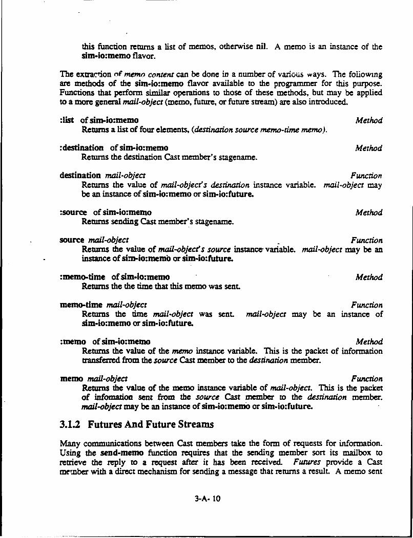
this function returns a list of memos, otherwise nil. A memo is an instance of thesim-io:memo flavor.
The exuaction nf memo content can be done in a number of varous ways. The followingare methods of the sim-io:memo flavor available to the programmer for this purpose.Functions that perform similar operations to those of these methods, but may be appliedto a more general mail-object (memo, future, or future stream) are also inuoduced.
:list of sim-io:memo MethodReturns a list of four elements, (destination source memo-time memo).
:destination of sim-io:memo MethodReturns the destination Cast member's stagename.
destination mail-object FunctionReturns the value of mail-object's destination instance variable, mail-object maybe an instance of sim-io:memo or sim-io:future.
:source of sim-io:memo MethodReturns sending Cast member's stagename.
source mail-object FunctionRetuns the value of mail-object's source instance, variable, mail-object may be aninstance of sim-io:memo or sim-io:future.
:memo-time of sim-io:memo MethodReturns the the time that this memo was sent.
memo-time mail-object FunctionReturns the time mail-object was sent. mail-object may be an instance ofsim-io:memo or sim-io:future.
:memo of sim-io:memo MethodReturns the value of the memo instance variable. This is the packet of informationtransferred from the source Cast member to the desanation member.
memo mail-object FunctionReturns the value of the memo instance variable of mail-object. This is the packetof infomation sent from the source Cast member to the destination member.mail-object may be an instance of sim-io:memo or sim-io:future.
3.1.2 Futures And Future Streams
Many communications between Cast members take the form of requests for information.Using the send-memo function requires that the sending member sort its mailbox toretrieve the reply to a request after it has been received. Futures provide a Castmember with a direct mechanism for sending a message that returns a result. A memo sent
3-A- 10

using the send-future function returns an instance of the sim-io:future flavor. Afterthe memo has been received and processed, the result is transparently routed back tothis object by SMULACT. The sending Cast member uses this future to determine when theresult is available, and to extract it after it has arrived.
send-future destination memo FunctionCreates, initializes, and returns an instance of the sim-io:future flavor. Thesource and memo-time instance variables are automatically set to the stagename andcurrent elapsed time of the sending member. A second instance, and duplicate copyof this future is placed in destination's futurebox at the beginning of the nexttime frame. This object is held on to, and periodically tested by the sending Castmember to determine when a reply to memo is received. When available, it then canbe extracted from this object.
In some cases, requests for information may not have one definitive reply. Instead,pieces of information may be returned at different times. SIMUJLACT allows two Castmembers to establish a future stream between themselves for returning results overtime. In this case, the send-future-stream function is used instead of send-future.
send-future-stream destination memo FunctionCreates, initializes, and returns an instance of the sim-io:future flavor. Thisinstance has its source and memo-time instance variables set to the stagename andcurrent elapsed time of the sending member. At the beginning of the next timeframe, a second instance and duplicate copy of this future stream is placed indestination's futurebox. This object is retained, and periodically tested by thesending Cast member to determine when one or more replies to memo have beenreceived. These replies are then extracted one at a time from the object.
Sending a future or future stream uses two instances of the sim-io:future flavor. Thesending Cast member's instance is referred to as the master, while the targettedmember's is known as the slave. Also, since futures and future streams are instances ofthe same flavor, we use one set of functions and methods for both. Therefore, someoperations perform slightly different tasks depending on whether a future or futurestream is referenced. These differences are pointed out. Likewise, some functions andmethods perform specific master or slave operations.
:future-state of sim-io:future MethodReturns t if a reply has been received from the targetted Cast member, otherwisenil.
future-state future-object of sim-io:future FunctionReturns t if a reply has been routed back toffuture, otherwise nil.
:reply of sim-io:future MethodReturns two values: the reply sent back to the future and the time the reply wassent. If no reply has been received, the two values returned are nil and nil. Forfutures, this method is non-destructive and will return the same values if used a
3-A- II

second time. Likewise, the fuaure-state operation wil continue to return t. Forfuture streams this method is destructive. Each time it is used, it removes thecurrent reply and reply-time from the stream. The future-state operation is thenused to determine when the next reply is available.
future-reply future-object of sim-io:future FunctionReturns two values: the reply sent back to the future and the time the reply wassent. If no reply has been received, the two values returned are nil and nil. Forfutures, this function is non-destructive and will return the same values if used asecond time. Likewise, the future-state operation will continue to return t. Forfuture streams this function is destructive. Each time it is used, it removes thecurrent reply and reply-time from the stream. The future-state operation is thenused to determine when the next reply is available.
:destination of sim-io:future MethodReturns the targetted Cast member's stagename.
:source of sim-io:future MethodReturns sending Cast member's stagename.
:memo-time of sim-io:future MethodReturns the time that this memo was sent.
:reply-time of sim-io:fluture MethodIf a reply has been received, :reply-time returns the time it was sent, otherwisenil. For future streams this is the sending time for the current reply.
reply-time future-object FunctionIf a reply has been routed back to future-object, the time it was sent is returned,otherwise nil. For future streams this is the sending time for the current reply.
receive-futures FunctionReturns and clears the contents of a Cast member's futurebox. If futures arepresent this function returns a list of futures, otherwise nil. A future is aninstance of the sim-io:future flavor.
:memo of sim-io:future MethodReturns the value of the memo instance variable. This is the packet of informationtransferred from the source Cast member to the destination member.
:send-future-reply reply &optional rest of sim-io.fiaure MethodFor futures, reply is routed back to the coresponding master and reply isreturned. Future streams can send one or more replies back to the master. Asingle reply or a list of replies is returned.
send-future-reply future-object reply &optional rest FunctionFor futures, reply is routed back to the coresponding master and reply is
3-A- 12

returned. Future streams can send one or more replies back to the master. Asingle reply or a list of replies is returned.
Futures and future streams use send-memo to route the communications that occur betweenthe master and slave components. This requires the Messenger to make an entry into itsaddress book for each master and slave. For futures, SIMULACT automatically removesthese entries when the slave sends its reply to the master. It is up to the user toclose a future stream when its usefulness has expired in order to help reduce Messengeroverhead. The following functions and method are provided for this reason.
:close of sim-io:future MethodSending this message to a future stream's master or slave closes the streampermanently and returns :closed. No further replies can be sent. All other futurestream operations remain enabled.
close-future-stream future-stream FunctionThis function closes future-stream, returns :closed, and prohibits the sending ofany further replies. All other future stream operations remain enabled.
:mode of sim-io:future MethodReturns :closed if the future stream has been closed, otherwise :master or :slaveis returned.
future-mode flaure-strewn FunctionReturns fiaure-sreams mode. If fure-strewn has been closed, :closed isreturned, otherwise :master or :slave is returned.
Note that eithe the master or slave can close the stream at any time. It is up to theuser to be aware this possibility, and to incorporate this feature in its use of futurestreams. For instance, Actor A may request information from Actor B by opening a futurestream. Sometime later Actor A may choose to close this stream when a sufficient numberof replies have been received to satisfy the request, or if the need for thisinformation no longer exists. In either case, it is inefficient for Actor B to continueprocessing this request. Therefore, it makes for good programming practice for Actorsto periodically test the mode of future streams in order not to waste their resources ona closed stream.
A slave may also close a stream using the same protocol as above, providing that themaster periodically checks the mode in order to avoid situation of waiting for a replyfrom a closed stream. Note that all replies sent prior to closing the stream areretrievable in the usual manner. A slave could also notify the master that the streamhas been closed by sending a reply stating this fact prior to closing the stream.
3.2 The Support Package Facility
The Support Package facility was developed to reduce memory requirements and tofacilitate modularity in application code. The underlying assumption that each Cast
3-A- 13

member has an independent environment implies that multiple copies of code are requiredfor agents performing identical tasks. A Support Package reduces this redundancyrequirement by allowing several Cast members to access the same copy of code from withintheir respective environments.
As in any shared memory system, an integrity violation would occur whenever a SupportPackage accesses or alters global information. (Global in the sense that more than oneCast member can access the same information.) To guard against these problems, SIMULACTdetects the potential occurrence of integrity violations and warns the user when aSupport Package tries to instantiate a global variable. Ideally, Support Packagesshould contain purely functional code. However, this restriction would severelyconstrain the code that can be placed into Support Packages.
There are two ways to use Support Packages other than for purely functional code. Oneway is for a Cast member to pass a local data structure as an argument to a SupportPackage function. If that function is "for effect", the result could then be boundappropriately. The other method requires the application programmer to use SIMULACT'ssimset functions. Basically, the simset functions allow Support Package code todirectly alter a global variable that is present in each of the Cast member packages.(Here, global means that each Cast member's environment has its own instance of thisglobal variable.) These functions are straightforward to use, but are built fromconcepts pertaining to Common Lisp's package system. Therefore, an overview of thepackage system will be given before introducing these functions.
3.2.1 An Overview of Common Lisp's Package System
Common Lisp's package system [Steele 1984] allows multiple name spaces for symbols, thusallowing for symbols with the same name to exist in different packages. A package is adata structure that maps symbol names to symbols. Only one package can be current at atime, and this package is bound to the variable *package*.
A symbol is a data object that has a separate slot (cell) for its print name, value,definition, property list, and package. A print name is a string used to identify thesymboL Since symbols are most commonly used to represent variables and functions inLisp programs, they have two distinct cells for this purpose. When used as a variable,its value is stored in the value cell. Likewise, a function's definition is held in thedefinition cell. The property list allows the user to give symbols other attributes aswell, without requiring a separate cell for each attribute. Instead, the attribute'sname and value are placed into the property list. A symbol can have an unlimited numberof attributes. When an attribute is accessed, the property list is searched for itsname and the corresponding value returned. When a symbol is created, the package itbelongs to is placed into the package cell. This value is referred to as the homepackage for this symbol.
The package system was created to allow modular programming in Lisp, without concernabout conflicts between symbol names. For instance, a programmer coding in package
3-A- 14

pkg-a could declare *x*, Oy*, and *z* to be global for his own use. Meanwhile, a secondprogrammer could declare *x* to be global in package pkg.b, without being aware of theexistence of *x* in package pkg-a.
Since modular systems need to interface between modules, symbols in packages areclassified as either external or internal. An external symbol is intended to be used byother packages, while internal symbols are not. Symbols are usually internal until madeexternal using some export command.
External symbols can be accessed by other packages using its qualifted name or throughpackage inheritance. A symbol's qualified name is constructed by appending the symbol'shome package name to its print name separated by a colon. For example, if *x* inpackage pkg-a is an external symbol, it can be accessed in package pkg-c via thequalified name pkg-a:*x*. If the symbol *x* in package pkg-a was inherited by packagepkg-c, it can be accessed by just its print name. Note that a name conflict wouldresult if package pkg-b tried to inherit *x* from pkg-a, since *x* already exists inpkg-b.
There is no way for a package to inherit the internal symbols of another package; apackage can only inherit external symbols. However, internal symbols can be accessedthrough the use of the double colon qualifier. For instance, if *z* is internal topkg-a, pkg-b can access it by pkg-a::zt.
When one package inherits the. external symbols of another, it is said to use thatpackage. All packages used by a package are placed into that package's use-list. Whena symbol is being "looked up" by a package, the package first searches through allexternal and internal symbols belonging to it. If the symbol is not found, the externalsymbols of the packages found in the use-list are searched until the symbol is found.If package pkg-a uses pkg.b, and pkg-b uses pkg-c, pkg-a does not inherit pkg-c'sexternal symbols. This is because only pkg-b is placed into pkg-a's use-list, and notpkg-c. Also, it is possible and sometimes necessary for pkg-a to use pkg-b, and forpkg-b to use pkg-a.
3.2.2 Support Packages Restrictions
Support Packages are used to reduce memory requirements for systems where Cast membersperform common tasks. They are also used to facilitate modularity in programming inexactly the same manner the package system does in Common Lisp. In fact, a SupportPackage is a Common Lisp package with a few additional constraints placed on it.
Global variables are not allowed in Support Packages in order to keep each Cast member'senvironment independent. If during the initialization of a Support Package, a defvar orsome other function that instantiates a global variable is used, SIMULACT interrupts thecurrent world initialization process and reports this problem to the user. SIMULACTalso checks the validity of each Support Package each time its simulation mode changes.This ensures the detection and notification of any instantiated global variable in a
3-A- 15

Support Package that may be incurred during the simulation.
Although global variables are not allowed in Support Packages, constants are. Theprogrammer may use defconstant to instantiate a symbol that is a constant and accessibleto any Cast member using that package. This is very useful method for representingstatic information about the system. This allows information of this sort to specifiedin one place, which makes the programmer's job much simpler when this information mustbe changed.
defconstant variable iniidal-value &optional docunentation Special FormDeclares variable to be a constant in the Support Package. initial-value isevaluated and the result is bound to variable. It is an error if any furtherbinding to variable is attempted.
documentation if used should be a string and is accessible via the documentationfunction.
Note that defconst cannot be used in place of defconstant. defconst allows the value ofthe constant to be changed without generating an error. SIMULACT will detect the use ofdefconst.
The only remaining restriction placed on Support Packages is that all symbols intendedto be used by Cast members must be external. SIMULACT requires that at least one symbolin a Support Package is made external via the export function. If not the user iswarned of this deficiency.
export symbols FunctionThe symbols argument may be a single symbol or a list of symbols. The symbolsexported by this function become external symbols of the support package. Notethis is not the same export function found in any other package, since the exportsymbol is shadowed in all Support Packages.
When a Cast member uses a Support Package, the Support Package is placed into the Castmember's package use-list. This allows Cast member code to access these externalSupport Package symbols using print names or qualified names. For systems with largenumber of symbols, Support Package symbol "look up" can be more efficient using thesymbol's qualified name.
3.2.3 The Simset Functions
SIMULACT's simset functions allow the programmer to write Support Package code that candirectly access and alter the local environment of a Cast member. There are tworequirements the programmer must keep in mind in order to use Support Packages in thismanner. First, all data structures referenced by this code must exist in each Castmember's environment. Secondly, when these dam structures are referenced by SupportPackage code, the programmer must use the simval and simset functions where symeval andset (or setq) would normally be used.
3-A- 16

The principle behind the simset functions is based on the fact that each Cast member'senvironment is contained its own package. This means that when Support Package code isaccessed by a Cast member, the current package is the calling member's package. Thesimset functions use the current package to access the appropriate data sructuresreferenced in its code.
As an example, consider a simple black board application with two Actors, A and B.During Actor initialization, SIMULACT places all of A's symbols in package actor-i andB's symbols in actor-2. Both Actors use the Support Package black-board, which containsthe black board code. This code assumes each Actor has two global variables: *bb* andagent-name*. The Support Package function make-black-board will be used to set *bb* toan instance of the black-board flavor, while *agent-name* is initialized directly froman initialization file.
Below is a sample of how this system could be implemented using the following fourfiles: BB-SUPPORT, BB-ACTOR, BB-ACTOR-1,'and BB-ACTOR-2. The code inBB-SUPPORT defines the black board system and is loaded into the black-board SupportPackage. In general, Cast members who use Support Package code have portions of theirenvironment structured the same. In this case, file BB-ACIOR contains this common codeand is loaded into both Actor environments. The remaining two files contain codespecific to each actor, thus BB-ACTOR-I and BB-ACTOR-2 are loaded into packages actor-Iand actor-2 respectively.
;;;File: BB-SUPPORT.ISP. 1 Created 6/9/87 19:13:55
(defflavor black-board ((name (simval '*agent-name*))(in-queue nil)(out-queue nil)
0))0))
(defun make-black-board ()(simset '*bb* (make-instance 'black-board)))
(export 'make-black-board)
;;;The remaining code
3-A- 17

;;; File: BB-ACTOR.LISP.1 Created 6/9/87 19:16: 11
(defvar *bb*)
(defvar *agent-name*)
(make-black-board)
The remaining code ...
;;; File: BB-ACrOR-1.LISP.1 Created 6/9/87 19:19:41
(setq *agent-name* "BB System A");;; The remaining code
;;; File: BB-ACTOR-2.LISP.1 Created 6/9/87 19:19:58
(setq *agent-name* "BB System B")The remaining code ...
If we look at the definition of make-black-board in BB-SUPPORT, we can see why simset isnecessary.
(defun make-black-board ()(simset '*bb* (make-instance 'black-board)))
This function will be used by both Actors A and B to perform the following operations:
(setq actor- 1::*bb* (make-instance 'black-board))(setq actor-2::*bb* (make-instance 'black-board))
The simset function is able to perform these operations because each Actor resides inits own package. Furthermore, when simet is called the variable *package* is bound tothe calling Actor's package. This allows simset to intern the *bb* symbol in thecurrent package and set it to the appropriate value. Likewise, simval interns itsargument in the current package and returns its value. This is how the name instancevariable of the black-board flavor is set to the correct agent name (*agent-name*).
3-A- 18

simset variable value FunctionWhen simset is called, the current package is the calling Cast member's package.variable is interned in the current package and bound to value. value is returned.
simval variable FunctionWhen simval is called, the current package is the calling Cast member's package.variable is interned in the current package and its value is returned.
simvar variable FunctionWhen simval -is called, the current package is the calling Cast member's package.variable is interned in the current package and returned.
In order to implement this example without using a Support Package, each Actor packagewould be required to have its own definition of the black board system. This could beachieved by simply loading a file similar to BB-SUPPORT into each Actor package. Thiskeeps the black board system modular, making updates to it straightforward.
3.3 The Peek And Poke Facility
The Peek and Poke facility can be invoked at any time when running SIMULACT as amonitoring and debugging tool It allows the user to enter the local environment of anyCast member residing on any host throughout the network. Any part of this localenvironment can be examined or changed at the discretion of the user.
Peek and Poke is invoked by mousing on the Peek & Poke item in the Executive Director'sMode Pane,. This action causes a menu displaying all host names to appear in the CommandPane (see Figure 4.a). After selecting the desired host, a second menu pops updisplaying all Cast names known to that host (Figure 4.b). When the Cast member ofinterest is selected, the Peek and Poke window is exposed on top of the Actor and GhostDisplay Area.
The Peek and Poke window is similar to the Lisp Listener, in that it executes a basicread-eval loop. Lisp forms are typed in at the keyboard and evaluated in the selectedCast member's top-level environment. The result is returned to the Peek and Pokewindow.
Error handling by the Peek and Poke facility is not interactive. When errors occur theyare reported to the window and control is returned bacz to the read-eval loop. However,some edit type errors are detected prior to evaluation, which can be corrected by theuser.
3-A- 19

SIMULACT: Select Host To Peek & Poke
BLACKFRIARS ODEONGLOBE NO SELECT
a) Select host menu
SIMULACT: Select Cast Member To Peek & Poke
CANTON POTSDAMOGDENSBURG MADRIDMASSENA WADDINGTONLISBON NORWOOD
b) Select Cast member menu
Figure 4. Peek And Poke Window Generation.
3.3.1 An Example Of The Peek And Poke Facility
Suppose we are developing an expert system which is designed to route local telephonecalls through a small number of neighboring communities. The exact path each call takesis dependent upon the availability of resources that each community has, as well as thecurrent distribution of phone traffic.
In our representation of the system, we model each town with one Actor. There is aknowledge base associated with each town that is used to record and retrieve informationabout the current status of the town and over all network. Each Actor environment bindsthis knowledge base to the variable *kb*.
We have just completed a preliminary model and during our first run we discover aproblem. It seems the town of Madrid is not receiving its share of traffic. We suspendexecution and enter Madrid's environment using Peek and Poke. We quickly determine thatMadrid's knowledge base was initialized incorrectly, since it responds nil to the:available-resources query. At this point we suspect an error in its initializationfile and exit SIMULACT to correct it. Figure 5 shows the actual methodlogy used indetermining the source of the problem.
3-A- 20

SIMULACT: PEEK AND POKE FACILHTY (Cast Member: MADRID)<Type EXIT to continue>
Command: (send *kb* :name)MADRID
Command: (send *kb* :number-of-calls)0
Command: (send *kb* :available-resources)NIL
Command: exit
Figure 5. An Example Of Peek And Poke Used As A Debug Facility.
3.4 The Diary Facility
The Diary facility can be used as a debugging tool, or simply as a mechanism for postmortem analysis of system behavior. There are three levels of Diaries, all of which maybe independently active. The Executive Director's Diary, when turned on, records allinter-machine messages handled. A Director's Diary records all inter-machinecommunications involving itself, along with the local message activity between itsresident Cast members. The last type of Diary is at the Cast member level. Whenactivated, a Cast member's Diary records its own message activity, and all screenactivity initiated via the typical print and format functions.
When a Diary is activated, a corresponding file is opened in the SIM-WORLDS; directory.The default name for this file is "stagename.DIARY", where stagename is the stagename ofthe object for whom the Diary is being created. In all but one case, the user is askedto confirm the default file name or enter a different one. The exception being when aDiary is created during an "Old World Load".
There are three mechanisms for activating Diaries. First, during a 'New WorldGeneration" the initialization menu for the Executive Director, the Directors, and theCast have an entry to turn "On" or "Off" Diary Generation. Similarly, during a "CurrentWorld Edit", each edit menu has this same option. The remaining mechanism for turningon Diaries is invoked by mousing on the Turn On Diaries option of the Mode SelectionPane.
When the Turn On Diaries item is selected, a tv:multiple-choose menu pops up in theCommand Pane. This menu contains the stagenames of possible candidates whose Diaries
3-A- 21

are not currently on. Each entry in this Dia y menu is mouse sensitive and ishighlighted when selected. Mousing on the do it option turns on the correspondingDiary for each highlighted item. Selecting the All option will turn on all Diaries justas if each item in the menu was highlighted prior to mousing on Do it. The Abortoption exits this menu without turning any Diary on.
Diaries can be turned off in a similar fashion to turning them on. "Current World Edit"can be used to set the current state of Diary Generation to "Off' when editing, or theTurn Diaries Off choice in the Mode Selection Pane can be moused to generate a pop upmenu of all Diaries. Again each item in this menu is mouse sensitive allowing the userto specify which Diaries to terminate.
3.4.1 An Example Of The Diary Facility
As an example of the Diary facility, consider the situation where Actor "ACTOR-i"resides on one host, and Actor "ACTOR-2" resides on another. Suppose at time 842(millieconds) ACTOR- I sends ACOR-2 a memo, which is the first interaction between Castmembers in the emulation. The following is the Diary for ACTOR-2:
3-A- 22

;;;File: ACTOR-2.DIARY Created 8/23/87 19:13:55
SIMULACT's Diary Facility
:STAGENAME "ACTOR-2":ALIAS-NAMES NIL:CAST-TYPE ACTOR:SUPPORT-PACKAGES NIL:DIARY-FLAG T:DIARY-NAME "ACTOR-2.DIARY":TIME-FRAME 1000:SCRIPT-FUNCrION BASIC-ACTOR:INIT-FUNCTION NIL:INIT-FILES ("ACTOR")
<<Receiving memo at 1000>>Destination: "ACTOR-2"Source: "ACTOR-I"Memo time: 842Memo: "ACTOR-i :STATUS T"
<<Renieving memo at 1033>>Destination: "ACTOR-2"Source: "ACTOR-I"Memo time: 842Memo: "ACTOR- i :STATUS T"
The first portion of this Diary contains ACTOR-2's biography, which is a description ofACTOR'2's inidalization as specified by the programmer. Information such as theActor's stagename and script function can be very useful to help identify which agentthis Diary belongs to, as well as providing some insight to its overall functionality.
Immediately following the biography is a log ACTOR-2's message activity. This log showsthat at time 1000 (milliseconds), ACTOR-2 received a message from ACTOR-i. Note thatACTOR-i sent this memo at time 842. The delay is a prevalent because SIMULACT onlydistributes mail between time frames. Although this memo was received at time 1000, itcan be seen that ACTOR-2 did not retrieve it until time 1033. Remember, it is up to theapplication code to periodically check its mailbox (memos-p) for mail, and then toretrieve it when suitable (receive-memos).
3-A- 23

This next Diary is at the Director level, and describes ACTOR-2's Director:
;;;File: DIRECTOR-ODEON.DIARY Created 8/23/87 19:13:56
SIMULACT's Diary Facility
:STAGENAME VDIRECTOR-ODEON":ACTORS ("ACTOR-2"):GHOSTS NIL:NUMBER-OF-ACTORS 1:NUMBER-OF-GHOSTS 0:SUPPORT-PACKAGE-P NIL:SUPPORT-PACKAGES NIL:DIRECTOR-PANE-CONSTRAINT :HORIZONTAL:DIARY-FLAG T:DIARY-NAME 'DIRECTOR-ODEON.DLARY":TIME-FRAME 1000
<<Received memo from Executive Director at 1000>>Destination: "ACTOR-2"Source: "ACTOR-I"Memo time: 842Memo: "ACTOR-I :STATUS r
<<Delivering memo to Cast member at 1000>>Destination: "ACTOR-2"Source: "ACTOR-1"Memo time: 842Memo: "ACTOR-I :STATUS r
Again, we see a biography, this time belonging to Director "ODEON". The log thatfollows is a history of message traffic handled by the Director's Messenger. Note thatthe Diary at this level indicates from who the message was received from, and to whom itwas deliver,. to. It does not record when ACTOR-2 retrieves it from its mailbox.
Finally, we have the Executive Director's Diary:
3-A- 24

;;;File: EXECUTIVE-DIRECTOR.DIARY Created 8/23/87 19:13:57
SIMULACT's Diary Facility
:STAGENAME "EXECUTIVE-DIRECTOR":DIRECTORS ("BLACKFRIARS-DIRECTOR" "ODEON-DIRECTOR"):OTHER-HOST-NAMES ("ODEON"):*TIME-FRAME* 1000:QUANTUM 6:DIARY-FLAG T:DIARY-NAME "EXECUTIVE-DIRECTOR.DIARY":MODE-SELECT-PANE-SIZE :LARGE:CURRENT-WORLD-NAME ' DIARY-EX":AUTHOR "DOUG":AUTHOR-COMMENT "SIMPLE EXAMPLE OF THE DIARY FACILITY.":CREATION-TIME "19:10:02, Sunday August 23,1987"
<<Received memo from Director Messenger at 1000>>Destination: "ACTOR-2"Source: "ACTOR-i"Memo time: 842Memo: "ACTOR-1 :STATUS T"
<<Delivering memo to Director Messenger at 1000>>Destination: "ACTOR-2"Source: "ACTOR-i"Memo time: 842Memo: "ACTOR-1 :STATUS T"
Although this is a trivial example, the power behind the Diary facility can be seen. Itcan be used to trace system activity and to monitor the flow of information betweenagents. This information can prove to be invaluable when trying to determine an agentslack of response, or wrong response to the cr'rent state of the system. Also forsystems which seem to performing adequately, this information can be used to betterunderstand system performance.
3-A- 25

3.5 The Gauge Facility
During the development of any complex system, it is often convenient to monitor systemparameters. These measurements can convey a great deal of statistical information aboutthe system. For instance, this information can be used to characterize systemperformance, to monitor system resource allocation, or to measure any other systemattribute. SIMULACT provides this capability to user through its Gauge facility.
3.5.1 The Gauge Pane
SIMULACT's Gauge Pane (see Figure 6) is the interface between the Gauge facility and theuser. This pane is broken into two segments: one for SIMULACT's gauges and the otherfor user defined gauges. The gauges displayed by SLMULACT reveal the current elapsedtime of the system, the current mode of operation, and the time frame ratio.
Top of saw*e Pan
-- SIMULACr GAUGES -*-
Elapsed Tune: 00:03:42Simulation Mode: run
Time Frame Ration: 1.056
-- USER GAUGES --
Cycle Count: 23Cycle Freq: 0.104
Boam ofs" gPam
Figure 6. SIMULACT's Gauge Pane.
3.5.2 SIMULACT Gauges
Elapsed-Time GaugeThe Elapsed-Time gauge displays the system's current elapsed time inhours:minutes:seconds. This value is bound to simulact:*elapsed-time* and can beaccessed by the application programmer.
simulact:*elapsed-time* VariableThe value of this variable is the current elapsed time of the system in
3-A- 26
milliseconds. SIMULACT guarantees that the elapsed time associated with any givenActor is greater than or equal to this value, but less than this value plus onetime frame.
Simulation-Mode GaugeSIMULACr's current mode of operation is displayed by this gauge. The current modeis changed via the mouse sensitive Mode Pane, which is only responsive whenSIMULACT's current mode is "run" or "pause".
Time-Frame-Ratio GaugeThis gauge is a measurement of SIMULACT's distributed performance. It is definedas:
(elapsed wall time)
(sum of all Actor elapsed time)
This ratio times the number of Actors in the system provides an estimate of howmuch time is required by SIMULACT to execute one time frame. For the idealsituation involving no overhead, this ratio would be 1.00, 0.50, and 0.33 for one,two, and three machine distibutions respectively.
The Elapsed-Time and Time-Frame-Ratio gauges are updated automatically at the mrtespecified by the variable simulact:*gauge-refreh-interval*. This interval is relativeto the elapsed time of. the system and defaults to 1 second. The Simulation-Mode gaugeis refreshed each time SIMULACT's mode of operation is changed by the user.
*simulact:*gauge-refresh-interval* VariableThe value of this variable is the interval of elapsed time that passes betweenGauge Pane updates and is measured in milliseconds. Its default value is 1000milliseconds ( 1 second).
3.5.3 User Gauges
Other gauges can be defined by the application programmer and placed into the Gauge Paneat any time by the make-gauge function. For instance, a gauge can be a permanent partof the system defined by application code, or it may be created through the Peek andPoke facility for debug purposes. In general, a gauge is used to display the value of avariable or Lisp form whose value reflects the current state of the modeled system.
make-gauge name form &rest options FunctionThe make-gauge function instantiates and returns an instance of the sim-io:gaugeflavor. Depending on the value of the :local init-option, the gauge is eitherglobal or local. If global, an entry for this gauge is placed in each Gauge Panethroughout the network, otherwise the gauge is only entered into the Gauge Pane ofthe Lisp machine executing this function.
3-A- 27

name is used to identify the gauge and must be a string. The value of name alongwith the gauge's value is what appears in the Gauge Pane.
The value of a gauge is determined by form. There are three possible form types:string, symeval, or function. The form is represented as a list, whose firstelement is one of the keywords :string, :symeval, or :function.
:string
Format: (:string)
The :string type allows name to be entered into the Gauge Pane without anassociated value. This technique can be used to enter headings into the GaugePane.
:symeval
Format (:symeval symbol)
The :syneval type displays the value bound to symbol in the Gauge Pane. Notethat symbol must be a global symbol.
:function
Format: (:functionfunction &rest args)
The :function type passes functon and its arguments (if any) to eval eachtime the gauge is evaluated.
options is a list of keywords followed by values (see section 3.5.4).
3.5.4 make-gauge Options
User defined gauges may be global or local. A global gauge is visible throughout thenetwork in each Gauge Pane (refer to section ?.?). A gauge is considered local when itonly appears in the Gauge Pane of the Lisp machine on which the make-gauge function wasexecuted. The :local init-option of make-gauge is used to make a gauge local.SIMULACT's Elapsed Time, Simulation Mode, and Time Frame Ratio gauges are global
:local t-or-nil (for make-gauge) Init OptionThe default is nil. If this is specified as t, the gauge will be a local gauge.
Since gauges are dynamic, their values are subject to change as the simulationadvances. This means that SIMULACT must periodically re-evaluate the value of eachgauge, as well as to update each Gauge Pane in order to reflect these changes. Therefreshing of each Gauge Pane is done automatically by SIMULACT at a rate specified by
3-A- 28

the value of simulact:*gauge-refresh-interval*. The rate at which each gauge isevaluated is set by the :update , it-option of make-gauge. This value defaults to 5seconds.
:update interval (for make-gauge) Init Optioninterval is an integer amount of time measured in sixtieths of a second used toregulate the update frequency of a gauge. If not specified, this interval defaultsto 300 sixtieths of a second (5 seconds).
3.5.5 User Defined Gauge Example
As an example of the Gauge Facility, lets consider the code that produced the two UserGauges shown in Figure 6. Here we have an application that is cyclic in nature. At theconclusion of each cycle, the global variable *cycle* is incremented. There are twoparameters of interest: the total number of cycles and the number of cycles per second.The following is a listing of code that produced these two gauges (only codespecifically related to the gauges is shown):
An Application Cyclic In Nature
Global variables
(defvar *cycle* 1) ;incremented during each cycle
Function definitions
(defun cycle-frequency ()(format nil "-5,3F" ;floating point number (x.xxx)(if (> simulact*elapsed-time* 0)
( *cycle* (/ simulact*lapsed-time* 1000.0))0)))
Make gauges(make-gauge "Cycle" '(:symeval *cycle*))(make-gauge "Cycle Freq: '(:function cycle-frequency))
3.6 The Controlled Program Wait (CPW) Facility
The controlled program wait (CPW) facility is a user invoked mechanism designed toincrease system performance. The use of this facility can significantly reduce systemrun time, which is achieved by not processing idle Cast members during the time framecycle. Instead, for each time frame that a member is idle, its elapsed time componentis incremented by one time frame. This technique reduces the consumption of system cputime, while preserving the elapsed time relationship among Cast members within thedistributed testbed environment.
3-A- 29
The application programmer invokes the CPW facility via the cast-wait function. This istypically done in the application code when it is clear that a member cannot continueuntil some action occurs. For example, suppose in your system there is a Knowledge BaseManager (kbm) whose job is to respond to queries. If these queries are implementedusing futures, the kbm's top level function could have the following appearance:
(do 0 ((futures-p)))
In this implementation, it can be seen that an idle kbm continues executing the do loopuntil a query is received. In an environment where a substantial amount of waiting ofthis nature is incurred, SZULACT would consume valuable cpu time emulating these waitstates.
The controlled program wait facility provides an alternative to these type ofsituations. For our kbm example, the following code would enhance SIMULACT'sperformance by placing the idle kbm into CPW mode until a query is received:
(cast-wait #'futures-p)
This implementation does not allow the kbm process to run again until a future isreceived. When it does eventually run, its elapsed time will reflect the the amount oftime that it was idle.
In general, when an Actor executes the cast-wait function, its current time slice isimmediately interrupted and the Actor's process enters CPW mode. Once in this mode, thepredicate function passed by cast-wait is then executed at the beginning of eachsuccessive time frame. For as long as this function returns NIL, this process does notrun and its elapsed time is incremented by one time slice for each time frame cycle.
3-A- 30

When the predicate returns non-NIL, the process is taken out of CPW mode and resumesrunning where it left off.
The cast-wiat function can also be executed in a Ghost's environment. However, due tothe differences between the roles of Ghosts and Actors, the use of the CPW facility by aGhost is slightly different. An Actor's script function is written never to terminateand runs in its own process. This allows the CPW facility to essentially interrupt andthen resume the Actor's process. On the other hand, a Ghost's script function mustterminate, since it is executed at the beginning of the time frame for its affect on thecurrent state of the emulation. Also, all Ghost script functions run in the SIMULACTprocess. For these reasons, when a Ghost executes a cast-wait there is no immediateaffect. The Ghost's script function continues running until it terminates. It is atthe beginning of the next time frame that the Ghost will be in CPW mode.
Once a Ghost is in CPW mode, it will be the predicate function that was passed tocast-wait that gets executed at the start of each successive time frame. A Ghost willremain in CPW mode until this predicate returns nonNiL. It at this point that theGhost's script function will again be allowed to run.
cast-wait predicate &rest args FunctionExecuting the cast-wait function places the Cast member into CPW mode. For anActor, the Cast member's process is immediately interrupted until the Actor is nolonger in CPW mode. When an Actor exits from CPW inode, its suspended process isresumed at the point of interruption. When cast-wait is executed by a Ghost, its.script function continues running until it terminites nattually, then it is in CPWmode. When a Ghost exits CPW mode, its script function is then executed at itsbeginning, not at the point where the cast-wait was executed.
A Cast member remains in CPW mode until the predicate function applied to argsreturns non-NIL. While in CPW mode, the Cast member's elapsed time is incrementedby one time frame for each time frame it was in CPW mode.
3-A- 31

A DISTRIBUTED DEVELOPMENT ENVIRONMENT
FOR DISTRIBUTED EXPERT SYSTEMS
Douglas J. Macintosh and Susan E. ConryElectrical and Computer Engineering Department
Clarkson UniversityPotsdam, New York 13676
Electronic Address (BITNET): DOUGMAC@CLVMS or CONRY@CLVMS
Abstract
In this paper, we describe an environment intended to aid the development ofapplications involving distributed problem solving. Specifically, we present a domainindependent development and simulation facility which permits rapid prototyping,interactive experimentation, and ease of modification of such systems.
Our environment, called SIMULACT, is based on a model which regards intelligentagents as semi-autonomous problem solving agents which interact with one another bymeans of a message passing paradigm. This system is currently implemented on aSYMBOLICS 3670andonanetworkofLISPmachines which incorporates both TI EXPLORERand SYMBOLICS machines.
3-B. 1

1. Introduction
Distributed problem solving systems have received increasing attention in the AIcommunity. Two factors have motivated this phenomenon. First, the advent of largeparallel machines and the development of small, powerful microprocessor based systemshave encouraged research on problems related to parallel and distributed AI systems.Secondly, research in distributed problem solving has been driven by the observationthat a number of important applications are inherently distributed. Examples includedistributed situation assessment, distributed sensor nets, air traffic control, andcontrol of geographically distributed systems such as communications systems and powertransmission networks.
It is easy to envision application environments in which on the order of ten tofifty semi-autonomous agents might be cooperaively solving a problem. In such anapplication, a distributed problem solving system would generally be implemented as adistributed system with as many independent processors as there are agents in thesystem. It would be prohibitively expensive to build a network of processors for thepurpose of providing a testbed in which feasibility studies could be performed andinitial prototype systems developed. The alternative of simulating the desired systemon a single processor is not attractive, since testing a system of this magnitude on asingle LISP machine would probably require time consuming simulation runs for evaluationpurposes. A facility which permits a network of k machines to emulate the behavior of anetwork of n machines (where n > k) would provide an attractive alternative.
In this paper, we describe SIMULACT, a development environment for distributedproblem solving systems which provides such a facility. The underlying model of problemsolving which is employed regards the problem solving system as a collection ofsemi-autonomous agents which cooperate in problem solving through an exchange ofmessages. The system is modular: each agent is essentially an independent module whichcan easily be "plugged in" to the system. An agent's interaction with other agents inthe system is totally flexible, and is user specified. Neither the form nor the contentof inter-agent messages is specified by SIMULACT itself. In addition, the user cansuspend execution at any time, examine the state of any agent, modify the state, theknowledge base, or even the code of an agent, and resume execution. A trace facilitymakes post-mortem examination of activity feasible, and a guage facility allows the userto instrument the system in a very flexible manner.
2. Background
The architectures of the distributed Al systems that have been developed havelargely been driven by the nature of the application. For example, the DVMT [Lesser andCorkill 1983] is clearly a descendent of the HEARSAY systems, and this has been naturalbecause the signal interpretation tasks involved in vehicular tracking are similar innature to those of speech recognition. There have been very few efforts directedtowards the problem of establishing a domain independent environment suitable for thedevelopment, testing, and debugging of distributed applications.
3-B- 2

One of the notable exceptions is MACE (Multi-Agent Computing Environment) [Gasser1986]. This system is a development and execution environment for distributed agents.It essentially provides a tool for programming multiprocessor systems in an objectoriented fashion. In MACE, agents are regarded as intelligent entities, each of whichis capable of performing tasks. These agents are directed and organized by theprogrammer through the specification of inter-agent relationships together with highlevel directives and constraints on behavior. Agents in MACE are implemented asproperty lists of the agent name, so only one copy of an agent may reside on a givenprocessor. By contrast, in our system multiple instances of a given agent type can beresident on a processor, thus providing greater flexibility to the user.
Among those systems that are intended for development of distributed applications,most have been designed with the intent of gaining as much speed in execution aspossible. Examples of this type of system are found in Stanford's CAGE and POLIGON.Both of these systems are designed for parallel execution of applications built usingthem and are based on a blackboard model of problem solving. CAGE [Aiello 1986]provides a problem solving framework which is based on the assumption that developmentwill proceed on a multiprocessor system involving up to a hundred or so processors withshared memory. The user must specify explicitly what is permitted to run in parallelPOLIGON [Rice 1986], on the other hand, is designed to be run on distributed memorymultiprocessor machines involving a large number (hundreds or thousands) of processors.High bandwidth interprocessor communication is necessary for a successful implementationof POLIGON. A number of primitive operations (such as rule evaluations and blackboardupdates) are ;utomatically done in paralleL
Both CAGE andPOLIGONhave programming languages associated with them. As in oursystem, these languages facilitate the writing of application programs and provide alayer of abstraction between the user and the system's implementation details. Unlikeour system, CAGE and POLIGON have been devised in an attempt to investigate issuesrelated to exactly how much speedup can realistically be anticipated when AI programsare run in parallel environments.
In the following two sections, we discuss SIMULACT 's system structure andconcurrency control mechanisms. We also describe the five user interface facilities,which were designed to make SIMULACT attractive as a development environment. Weconclude with a brief discussion of experiments we have performed in order to assess thedegree of overhead due to SIMULACT as implemented on one and two machines.
3. System Structure
SIMtLACT is a distributed system that allows n agents to be modelled on kmachines, where n > k. Each agent runs asynchronously and coordinates its activity withthat of other agents through the exchange of messages. The activities performed by eachagent are assumed to be complex, so that the parallelism is coarse grained. SIMULACTallows the programmer to write code in Lisp as though there were as many Lisp machinesin the network as there are agent- in the distributed system being developed.
3-B- 3

As is evident from Figure 1, SI4ULACT is comprised of four component types:Actors, Ghosts, Directors, and an Executive Director. Actors are used to model agentsin the distributed environment. Each Actor type is individually defined, and used as atemplate to create multiple instances of that Actor type. An Actor is a self containedprocess which runs in its own non-shared local environment. Although Actors runasynchronously, the elapsed CPU time for each actor never varies by more than one "timeframe'. These Actors closely resemble the entities described in Hewitt's "ActorApproach To Concurrency" (Hewitt 1986].
ACTOR ACTOR GHOST HS
a) Host level strucMuxe
EXECUTIVE DIRECTOR
OtICTOR I DIRECTOR k
ATOR AC700OR M0T A~S CTo On IS C4S
I 7 - , -,1
b) Nertwrk level smucnwe
Figure I
Ghosts are used in SIMULACT to generate and inject information into the modelthat would naturally occur in a "real" distributed expert system. They do not representany physical component of the modeL For example, external inputs (alarms, sensors,etc.) affecting the state of the system can be introduced via Ghosts, as well as inputsthat reflect the "side effects" of the systems activities. Ghosts can also be used to
3-B- 4

inject noise or erroneous information into the system so that issues concerningrobustness can be easily investigated. The performance of an expert system can bemonitored in subsequent runs through the simple modification of these Ghosts.
Due to the similarities between Actors and Ghosts, we refer to them as Castmembers. Each Cast member has a unique "stagename" and a "mailbox" used by the thecommunication facility in muting messages among members. Each also has a "scriptfunction" which defines its high level activity.
The control structure residing at each host processor in SIMULACT 's distributedenvironment is known as the Director. The Director is responsible for controlling theactivities of the Cast members at that site, and for routing messages to and from thesemembers. These activities are assigned to the Grip and Messenger respectively. Theresponsibilities of the Grip range from setting up and initializing each Cast member'slocal environment to managing and executing the Actor and Ghost queues. The Messengeronly deals with the delivery and routing of messages. When a message is sent, it isplaced directly into the Messenger's "message-center". During each time frame, the Gripinvokes the Messenger to distribute the messages. Whenever the destination stagename isknown to the Messenger, the message is placed in the appropriate Cast member's mailbox.Otherwise, it is passed to the Executive Director's Messenger and routed to theappropriate Host.
There is one Executive Director in SIMULACT which coordinates all Cast memberactivities over an entire network. The Executive Director provides the link betweenDirectors necessary for inter-machine communications, directs each Grip so thatsynchronization throughout the network is maintained, and handles the interface betweenthe user and SIMULACT.
4. Concurrency Control In SIMULACT
Concurrent execution of n Actors on k machines (n > k) is emulated through theimposition of a "time frame" structure in execution. A time frame cycle breaks down tothree fundamental parts: invocation of the Ghosts, the distribution of mail by theMessengers, and invocation of the Actors. For SIMULACT distributed cver two hosts,Figure 2 depicts a representation of two time frames.
3-B- 5
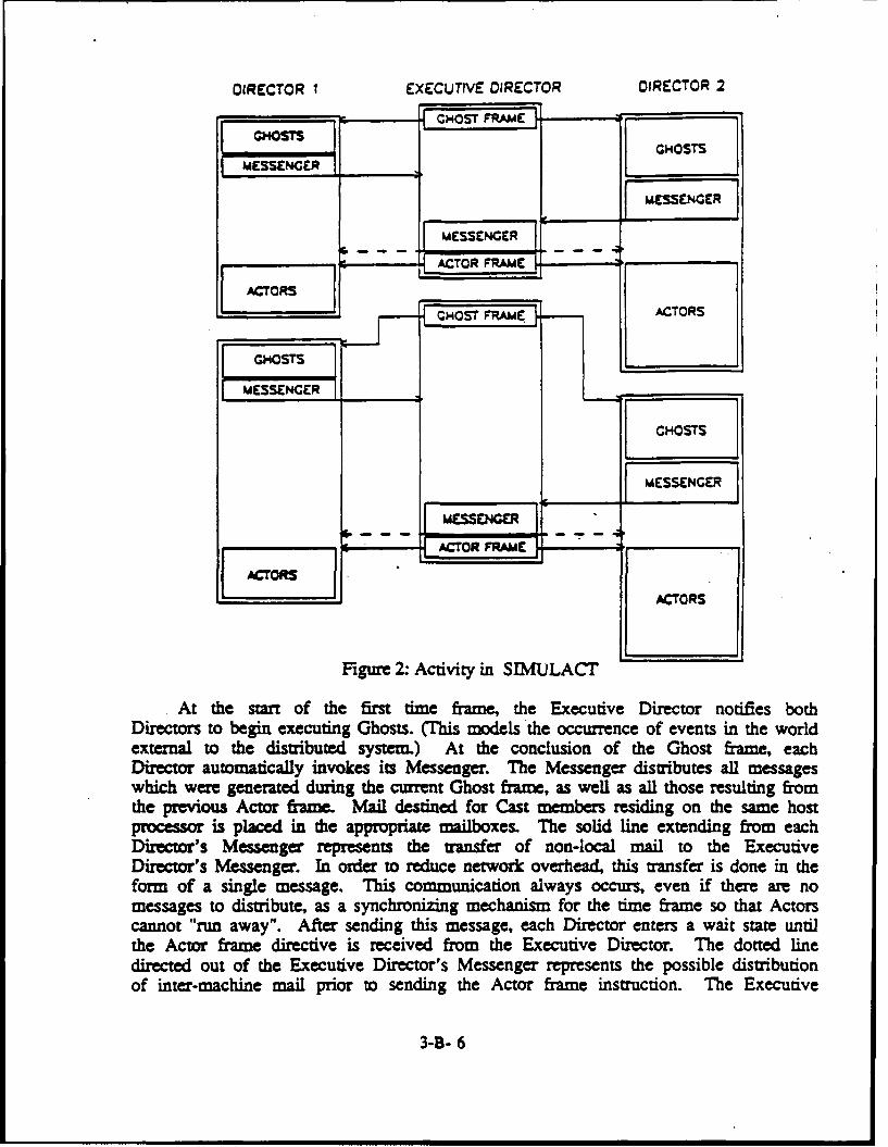
DIRECTOR I EXECUTIVE DIRECTOR DIRECTOR 2
GHOSTSRAM
GHOSTSMESSENGER
MESSENGRroMESSENGER
~~ACTOR FRAME "
ACTORS
FigureT 2:ACTOtRiSIMJLC
GHOSTS,,
MESSENGEtR
GHOSTS
MESSNGERMESSENGER
C ACTOR FRAM
ACT"ORS
1E 11ACTORS
Figure 2: Activity in SIWULACr
At the start of the first time frame, the Executive Director notifies bothDirectors to begin executing Ghosts. (This models the occurrence of events in the worldexternal to the distributed system.) At the conclusion of the Ghost frame, eachDirector automatically invokes its Messenger. The Messenger distributes all messageswhich were generated during the current Ghost frame, as well as all those resulting fromthe previous Actor frame. Mail destined for Cast members residing on the same hostprocessor is placed in the appropriate mailboxes. The solid line extending from eachDirector's Messenger represents the transfer of non-local mail to the ExecutiveDirector's Messenger. In order to reduce network overhead, this transfer is done in theform of a single message. This communication always occurs, even if there are nomessages to distribute, as a synchronizing mechanism for the time frame so that Actorscannot "run away". After sending this message, each Director enters a wait state untilthe Actor frame directive is received from the Executive Director. The dotted linedirected out of the Executive Director's Messenger represents the possible distributionof inter-machine mail prior to sending the Actor frame instruction. The Executive
3-B- 6
Director's Messenger is invoked immediately following the receipt of the last Director'sMessenger communication.
Upon receiving an Actor frame command from the Executive Director, the Director'sMessenger is invoked to distibute any inter-machine messages that may have beenreceived. Next, each Actor is allowed to run for one time slice (time frame). At thispoint the Executive Director immediately enters its next time frame cycle, sends theGhost frame command, and waits for all the Director Messengers to send their nextsynchronizing signal. Again in the second time frame of Figure 2, it is Director 2which requires the most time to run.
5. User Interface Facilities
There are. five user interface facilities that will be discussed in this section.These facilities provide mechanisms for inter-agent communication (Mail), code sharing(Support Packages), interactive monitoring and debugging (Peek and Poke), post mortemtrace analysis (Diary), and runtime monitoring (Guage). These features were designed tomake SIMULACT more attractive as a development environment for expert systems.
The Mail Facility
Depending on the constraints and characteristics of the expert system beingdeveloped, the application programmer constructs a network environment of intelligentagents which collectively work together towards the satisfaction of one or more goals.
SIMULACT provides several mechanisms allowing these agents to communicate withoutbeing concerned with implementation details.
In general, communication between agents occurs when one agent sends a packet ofinformation to another, addressing the target agent by its stagename. The format ofthese packets is not specified by SIMULACT. Instead, it is left up to the user toformulate a syntax that is convenient in the context of the system being developed.
The "send-memo" function is the simplest mechanism one Cast member can use tocommunicate with another. This function accepts two arguments: the stagename of thedestination Cast member and the memo to be sent. Automatically, at the beginning of thenext time frame, this message will appear in the destination agent's mailbox. Each memocontains the stagename of the sending member, as well as a timetag indicating when itwas sent. It is the responsibility of each Cast member to periodically to check itsmailbox for incoming messages.
Many communications between agents take the form of requests for information.Using the send-memo function requires that a sending agent sort its mail to retrieve thereply to a request after it has been received. Futures [Davies 1986; Halstead 1985;Rice 1986; Schoen 1986] provide an agent with a mechanism for sending a message thatreturns a result. A memo sent using the future facility in SIMULACT returns a datastructure called a future. After the memo has been received and processed, the result
3-B- 7
is routed back to this data structure. The sending agent uses this future to determinewhen the result is available, and to extract it after it has arrived. SIMULACTprovides this capability through the "send-future" function.
In some cases, requests for information may not have one definitive reply.Instead, pieces of information may be returned at different times. SIMULACT allowstwo Cast members to establish a "future stream" between themselves for returning resultsover time. The user specifies criteria for determining when a future stream should beclosed.
The Support Package Facility
A Support Package contains code that can be accessed by several Cast members, thusreducing memory requirements. As in any shared memory system, an integrity violationcould occur whenever a Support Package accesses or alters global information. Theunderlying assumption concerning independent environments for each Cast member would beviolated. To guard against these problems, SIMULACT detects the pote'iial occurrenceof integrity violations and warns the user when a Support Package tries to instantiate aglobal variable. Ideally, Support Packages should contain purely functional code.However, this restriction would severely constrain the code that can be placed intoSupport Packages.
Them are two ways to use Support Packages other than for purely functional code.
One way is for a Cast member to pass a local data structure as an argument to a Support
Package function. If that function is "for effect", the result could then be boundappropriately. The other method requires the application programmer to use SIMULACT's"sim-set" functions. Basically, the site-set function allows the Support Package toalter a global variable that is present in each of the Cast packages. The goal of theSupport Package facility is to reduce overhead. Use of Support Packages does reduce theoverhead, but it does so at the expense of requiring that the user have more knowledgeabout SIMULACT 's implementation and Lisp packages (Steele 1984] than might bedesirable.
The Peek And Poke Facility
This facility can be invoked at any time when running an expert system as amonitoring and debugging tool. It allows the user to enter the local environment of anyCast member and to examine or change any part of its environment. The Peek and Poke isinvoked through a menu and displayed at the Executive Director's host. However, anyCast member residing on any host can be accessed.
The Diary Facility
The Diary facility can be used as a debugging tool, or simply as a mechanism forpost mortem analysis of system behavior. There are three levels of Diaries, all ofwhich may be independently active. The Executive Director's Diary, when turned on,records all inter-machine messages handled. Director Diaries record all local
3-B- 8

communications, while Cast member Diaries record all screen activities. All Diaries are
written to files to permit post mortem examination.
The Gauge Facility
This facility is used by SIMULACT to display the current elapsed run time,current mode of operation, and the "time frame ratio" which is a measure of SIMULACT 'sdistributed performance. It can also be ,ised as a runtime monitoring device by theuser. The "make-gauge" function accepts two arguments: a string to be displayed inSIMULACr 's gauge window and a function to be evaluated periodically. SIMULACT
automatically evaluates this function and updates the gauge window appropriatelythroughout the execution of the expert system.
6. Performance Issues
The overhead incurred in managing the emulation of a distributed environment is oneimportant measure of system performance. In this section we present preliminary resultsindicating the overhead incurred by SIMULACT as implemented on one and two machines.We first outline the experiments which were performed, then discuss the resultsobtained.
Our experiments were designed to obtain results that would assess SIMULACr 'sbehavior as the number of messages per time framnle increases. In each of theexperiments, the number of messages per time frame, m, was varied over the range 0 to10n, where n is the number of Actors in the system. Each Actor process workedcontinually, consuming its total time slice allowed per time frame. Thus when n = 0, wemeasured SIMULACT 's best case performance. It should be pointed out that in thedistributed case where n > 0, the number of messages per time frame in our experimentsrepresented entirely inter-machine communications, emulating a worst case senario.
The measurement used to represent SIMULACT's performance was a "time frame ratio"gauge. This ratio is defined as:
(elapsed wall time)/(sum of all Actor elapsed time)
This ratio times the number of Actors in the system provides an estimate of how muchtime is required by SIMULACT to execute one time frame. For the ideal situationinvolving no overhead, this ratio would be 1.0 and 0.5 for the one and two machine casesrespectively.
Figure 3a depicts our experimental results for SIMULACT running on a singleprocessor. Figure 3b shows the two processor results. In each case, data was collectedover a range of 1 to 40 Actors per processor and a one second time frame was specified.These results are preliminary and modifications to SIMULACT have already beenscheduled to enhance performance. Further testing is planned to observe the effect ofthree machine distribution as well as varying time frame sizes.
3-B- 9

1.25
1.20
1.15 - - -
1.10q." 5 n
en - 2 nI
1.00
1 2 a 6 10 20 40
NUMBER OF ACTORS (n)a) Single procmsor
1.21.1 - " - - - m- u IQ
0.
1. - -- - /
0.8 M-5 M
0.7
0.6
0.51 2 4. 6 8 10 20 40 80
NUMBER OF ACTORS ( n)b) Two pmCemrs
Figure 3: SIMULACT's Performance
For the single machine case with no message passing, SIMULACT 's overheadapproaches 4.5%. Similarly, the distributed case approaches 10% overhead. Both sets ofcurves indicate that as the number of messages per time frame increases, so does theoverhead. In fact, between 100 and 200 messages per time frame handled by the systemseems to be a saturation point for the Messenger. Currently the Messenger uses ana-list to associate stagenames with Cast members. We should see improvement when this
3-B- 10

is implemented as a hash table lookup. Also note that the distributed case aftersaturation degrades at a much faster rate. One explanation for this can be deduced fromFigure 2. All inter-machine messages are handled three times by different Messengersand must be sent over the Lisp machine network. Messages among agents residing at thesame host processor are handled once by the Messenger and sent directly to theappropriate mailbox.
7. Concluding Remarks
In this paper, we have describe SIMULACT, an environment for the design anddevelopment of distributed expert systems. This system is currently running on anetwork of three Lisp machines.
SIMULACr has been particularly useful in the development of a distributedplanning system [Conry, Meyer, and Lesser 1986]. It has been used to expose the natureof message traffic in this planner and to develop and debug plan generation in adistributed environment. SIMLJLACT is also being used as an aid in the developement ofa distributed diagnosis system, an intelligent distributed knowledge base, and adistributed model for an express mail system. In each of these projects, SIMULACr 'smodularity and transparency have allowed us to concentrate our efforts on thedevelopment of these agents rather thaa on the problems associated with managing adistributed environment.
Acknowledgments
The Authors would like to express their appreciation for the contributions of theircolleagues Robert Meyer and Janice Searleman. Their suggestions and support have beeninvaluable. This work was supported in part by the Air Force Systems Command, Rome AirDevelopment Center, Griffiss Air Force Base, New York 13441-5700, and the Air ForceOffice of Scientific Research, Boling AFB, DC 20332 under Contract No.F30602-85-C-0008. This Contract supports the Northeast Artificial IntelligenceConsortium.
References
Aiello, N. 1986. 'User Diected Control of Parallelism; the CAGE System." In Proceedingsof the Expert Systems Workshop (Asilomar, Pacific Grove, CA., Apr. 16-18). DARPA,146-151.
Brown, H., C. Tonge, and G. Foyster. 1983. "Palladio: An Exploratory Environment forCircuit Design," IEEE Computer (Dec.): 41-56.
Conry, S. E., R. A. Meyer, and V. R. Lesser. 1986. "Multistage Negotiation inDistributed Planning", University of Massachusetts, Amherst Massachusetts 01003, COINS
3-B- 11

Technical Report 86-67 (Dec.).
Davies, B. 1986. "CAREL: A Visible Distributed Lisp." In Proceedings of the ExpertSystems Workshop (Asilomar, Pacific Grove, CA., Apr. 16-18). DARPA, 171-178.
Delagi, B. 1986. "Care User's Manual," Knowledge Systems Laboratory, Department ofComputer Science, Stanford University.
Durfee, E. 1984. "A Parallel Simulation of a Distributed Problem Solving Network." M.SThesis, Electrical and Computer Engineering, University of Massachusetts at Amherst.
Gasser, L 1986. "MACE, A Mlti-Agent Computing Environment." USC-DPS Group,University of Southern California (Mar.)
Halstead, R.H. 1985. "Multilisp: A Language for Concurrent Symbolic Computation." ACMTransactions on Programming Languages and Systems 7, no. 4 (Oct.): 501-538.
Hewitt, C. 1986 "Concurrency in Intelligent Systems." Al Expert (Premier): 44-50.
Lesser, V.R. and D.D Corkill. 1983. "The Distributed Vehicle Monitoring Testbed: A ToolFor Investigating Distributed Problem Solving Networks." The Al Magazine 4, no. 3(fall): 15-33.
Mac Intosh, D. I., S. E. Cory. 1987. " SLMULACT : A generic tool for simulatingdistributed systems." In Tools for the simulation profession (Orlando, FL., Apr. 6 - 9,1987) The Society for Computer Simulation, San Deigo, CA., 18-23.
Misra, 3. 1986. "Distributed Discrete-Event Simulation." ACM Computing Surveys 18, no.I .(Mar.): 39-65.
Moon,D.A. 1986. "Object-Oriented Programmingwith Flavors." In OOPSLA'86 ConferenceProceedings (Portland, OR., Sep. 29 - Oct. 2). ACM, Baltimore, MD., 1-8.
Rice, 3. 1986. "Poligon, A System for Parallel Problem Solving." In Proceedings of theExpert Systems Workshop (Asilomar, Pacific Grove, CA., Apr. 16-18). DARPA, 152-159,
Schoen,E. 1986. "TheCAOSSystem."KnowledgeSystemsLaboramtory,DepartmentofComputer
Science, Stanford University, Report no. KSL-86-22 (Mar.).
Steele, G.L. 1984. Common LISP. Digital Press, Burlington, MA.
Stefik, M. and D.G. Bobrow. 1986. "Object-Oriented Programming: Themes and Variations."The Al Magazine 6, no. 4 (winter): 40-62.
3-B- 12

SIMULACT: A GENERIC TOOL
FOR SIMULATING DISTRIBUTED SYSTEMS
Douglas J. MacIntosh and Susan E. ConryElectrical and Computer Engineering Department
Clarkson UniversityPotsdam, New York 13676
Abstract
This paper describes a generic tool for simulating and observing the behavior ofnetworks of distributed agents. Our system, called SIMULACr, provides a facility forhandling communication among a group of distributed agents. It does so withoutrequiring that the application programmer be aware of SIMULACT's implementationdetails. The goal of the system is not primarily one of achieving speed of executionthrough parallelism. Instead, it is assumed that the application is inherentlydistributed, and a natural framework for investigating network behavior is provided.
Our system is implemented in Lisp and runs on a network of Lisp machines. Theapplication programmer writes code in Lisp as though there were as many machines in thenetwork as there are agents to simulate. SDMULACT is a simulator shell that providesfacilities for message handling, instrumentation, and controlling the simulation. Italso transparently handles all overhead associated with executing the simulation.
3-C- 1

1. INTRODUCTION
In this paper we discuss SIMULACT, a generic tool for simulating and observing thebehavior of networks of distributed systems. Unlike many other systems for simulatingdistributed environments [Brown et al. 1983; Delagi 1986; Schoen 1986], the goal of oursystem is not primarily one of achieving speed of execution through parallelismInstead, it is assumed that the application is inherently distributed, and a naturalframework for investigating network behavior is provided. Our system is useful insimulating distributed systems in which processing agents collectively work togethertowards satisfaction of one or more goals. It is assumed that each agent runsasynchronously and can only communicate with neighboring agents through an exchange ofmessages. In addition, the activities performed by each agent are assumed to becomplex, so that the parallelism is coarse grained.
There are two fundamental approaches to discrete simulation: event driven and timedriven. Both of these simulation strategies make use of a clock to represent thecurrent elapsed time of a simulation and typically allow communications betweensimulated objects using time tagged messages. The fundamental difference between thetwo strategies lies in the way in which the simulation is controlled. In an eventdriven simulation, there usually is a data structure referred to as an "event-list".This list is used as a scheduling queue by the simulator. As the simulation advances,the scheduler removes from the event-list the entry having the earliest time tag, setsthe simulation's elapsed time to this time, and initiates the evaluation of this currentevent by invoking the appropriate process. During the simulation new events may begenerated and placed into the queue, current ones may be modified or removed, or thequeue may remain unchanged. In a time driven simulation, on the other hand, thesimulated elapsed time advances at a uniform rate (often termed the time frame). Theclock is incremented by one time frame at each stage rather than being advanced to thetime of the next scheduled process.
In order to simulate a physical system using these simulation techniques, it mustbe possible to model the system as a collection of discrete processes, each performing aspecific task. It is then the simulator's responsibility to execute code simulatingeach task in an order that is consistent with that of the physical system beingmodeled.
There are several limitations of conventional discrete simulation systems inmodeling networks of distributed agents. One is found in the time required to simulatesystems having a large number of events with many interactions. It is not uncommon fora simulation of a large system to run for hours, or even days. (This phenomenon is theunderlying motivation behind current research in the areas of distributed simulationarchitectures and techniques.) A second drawback of discrete simulation lies in theobservation that there are many physical systems that cannot be adequately modeled usinga discrete simulator. It may be unnatural or even impossible to view a system as acollection of discrete events which collectively perform some task. A third problem isassociated with assessing the real time components associated with a simulation.
3-C- 2

To illustrate the importance of real time issues, consider the problem of designinga distributed system that is to run on a network of cooperating microprocessors. Beforesuch a system is built, it may be desirable to simulate its behavior over severaldifferent network configurations. It is not enough for the simulation to determinewhether or not each configuration provides a viable solution to the problem. It mustalso provide some information as to how well each configuration performed the job (i.e.,how much real time would be required by the physical system to perform the job). It isnot always straightforward to determine the real time associated with a simulation. Anumber of discrete simulators use clocks that correspond to the event count, and not toany real time dimension [Durfee 1984; Lesser and Corkill 1983].
Each of these issues has been considered in the development of our system, and isaddressed in subsequent sections. SIMULACT is written in ZetaLisp and runs on theSYMBOLICS 3600 and the TI EXPLORER Lisp machines. Our implementation makesextensive use of the flavor facility in ZetaLisp to improve data encapsulation andfacilitate the modeling of environments in which a group of semiautonomous processes donot share a common memory. The current network testbed consists of one SYMBOLICS andtwo EXPLORERS.
2. SIMULATION STRUCTURE AND STRATEGY
SIMUJLACT is a distributed real time, time driven simulator capable of achievingimproved run time performance through the application of event driven and parallelprogramming strategies. In this section, we first describe the major components ofSIMULACT at a high level then discuss the simulation strategy employed by SIMULACT andsome details of its implementation.
2.1 Simulation Structure
SIMULACT has a modular structure comprised of four component types: Actors,Ghosts, Directors, and an Executive Director (see Figure 1). Actors play the part ofprocessing agents in a distributed system. Multiple instances of agents of the sametype in a system are easily incorporated in SIMULACr without requiring any special codedevelopment on the part of the user. Ghosts generate information about the environmentthat naturally occurs in a "real" distributed system and do not represent any physicalcomponent of the distributed system being simulated. The Director is responsible forcontrolling the simulation and all interactions between Actors and Ghosts at each host(there is one Director for each Lisp machine in the network). Finally, the ExecutiveDirector coordinates a simulation distributed over a network of Lisp machines. Ingeneral, Actors play the role of the entities being simulated, while the Director staysbackstage and tries to get realistic performance from the Actors. In the paragraphswhich follow, we describe the role of each of these system components in more detail.
2.1.1 Actors
Actors in SIMULACT closely resemble th%, entities described in Carl Hewitt's "ActorApproach To Concurrency" (Hewitt 1986]. Hewitt's Actors are self contained entities
3-C- 3
which work cooperatively in performing computation and can only be accessed via messagepassing. Sending and receiving messages are considered to be atomic operations, andmessages are accepted one at a time in the order they arrive. Each message, whenevaluated, may influence an Actor to create new Actors, send new communications to otherActors, or to specify the manner in which it will handle new messages.
In SIMULACT, Actors are also self contained and represent the fundamental structureused to simulate concurrency. Our Actors communicate asynchronously by routing messagesthrough the Director. Each Actor has a "stagename" that is known by its Director and isused in routing these messages. When a Director is asked to transmit a message, it doesso by either updating the appropriate Actor's "mailbox" directly, or routing the messageto the appropriate Lisp machine through the Executive Director (if the destination agentresides on a different host machine in the network). When an Actor decides to read itsmailbox, it has the responsibility of preserving the incoming messages and choosingwhich one, if any, it will currently respond to. The content and form of messages areindependent of SJMULACT, and are determined by the application programmer.
The connectivity of Actors may be fixed or dynamic depending on the physical systembeing simulated. In a rigidly connected system, each Actor knows the stagenames ofActors with whom it can directly communicate. It is also possible for an Actor to knowof the existence of a distant Actor to whom it can indirectly send a message. Insimulations where the physical connectivity is allowed to change depending on thecurrent state of the system, SIMULACT provides the capability of generating and managingappropriate stagenames on demand. This is analogous to situations in which Hewitt'sActors spawn new Actors [Hewitt 1986].
2.L2 Ghosts
One issue which must be addressed in any simulation is the representation of eventswhich occur in the external world and may have impact on the state of the simulation.Examples include external inputs to the simulation from its "global environment" as wellas inputs which reflect the "side effects" of the simulated system's activity. Ghostsgive the application programmer a facility for injecting these factors into thesimulation. For example, a Ghost can use its own event-list to send an Actor a messagesignaling the occurence of some event at a given time. A Ghost's event-list can easilybe altered to investigate the performance of the simulated system in subsequent runs.Ghosts can also be used to inject noise, or wrong information into the simulated systemso that issues associated with robustness can be easily investigated.
Actors and Ghosts are referred to as Cast members in SIMULACT, since they are verysimilar in structure. Each Cast member has a top level function associated with itreferred to as a "script function". The script function is written by the applicationprogrammer and is invoked by SIMULACT to initiate each Cast member's simulation.Differences between these two cast types are specified (in. implementation) throughdaemons associated with the Actor and Ghost data types. These differences arise fromthe fact that Actors represent the physical system and must be carefully controlled toachieve a realistic simulation. On the other hand, Ghost are considered part of the
3-C- 4

overhead associated with the simulation.
2.1.3 Directors
SIMULACT is a distributed simulator which runs on a network of Lisp machines. Eachhost in the network uses a Director to control the activity of Cast members residing atthat site, and to route messages to and from these Cast members. The Director assignsthese activities to the Grip and Messenger respectively. The responsibilities of theGrip range from setting up and initializing each Cast member's local environment tomanaging and executing the Actor and Ghost queues. The Messenger only deals with thedelivery and routing of messages. When a message is sent, it is placed directly intothe Messenger's "message-center". During each time frame, the Grip invokes theMessenger to distribute the mail. Whenever the destination stagename is known to theMessenger, the message is placed in the appropriate Cast member's mailbox. Otherwise,it is passed to the Executive Director's Messenger and routed to the appropriate Host.
2.1.4 Executive Director
There is one Executive Director in SIMULACT which coordinates the entire simulationover a distributed network. The Executive Director provides the link between Directorsnecessary for inter-machine communications, it directs each grip so that synchronizationthroughout the network is maintained, and it handles the interface between the user andSIMULACr.
2.2 Simulation Strategy And Implementation
In this subsection, we describe the simulation strategy employed by SIMULACTwithout giving extensive details regarding implementation. Mechanisms for controllingthe simulation are discussed first. Since SIMULACT is implemented in Lisp using anobject oriented programming style, there are two features of the system's implementationthat are described in more detail. This is done in the latter half of the subsection,where we discuss message handling protocols and mechanisms for improving efficiency.The reader who is unfamiliar with Lisp and object oriented programming may find ituseful to refer to [Moon 1986; Steele 1984; Stefik and Bobrow 1986].
2.2.1 Simulation Strategy
In SIMULACT, the components of the physical system being simulated are modeledsolely by Actors. Only Actors need to be considered when determining the current realtime associated with the simulation. For this reason, each instance of an Actor isimplemented as a process on a Lisp machine. In general, an Actor's script function iswritten by the application programmer so that it never "terminates". At any given time,the amount of CPU time spent by the Lisp machine in executing an Actor's script functioncan be determined. This CPU time, along with the Actor's CPW time (Controlled ProgramWait time which will be discussed in the next subsection), are used in computing theelapsed real time for a given Actor.
3-C- 5
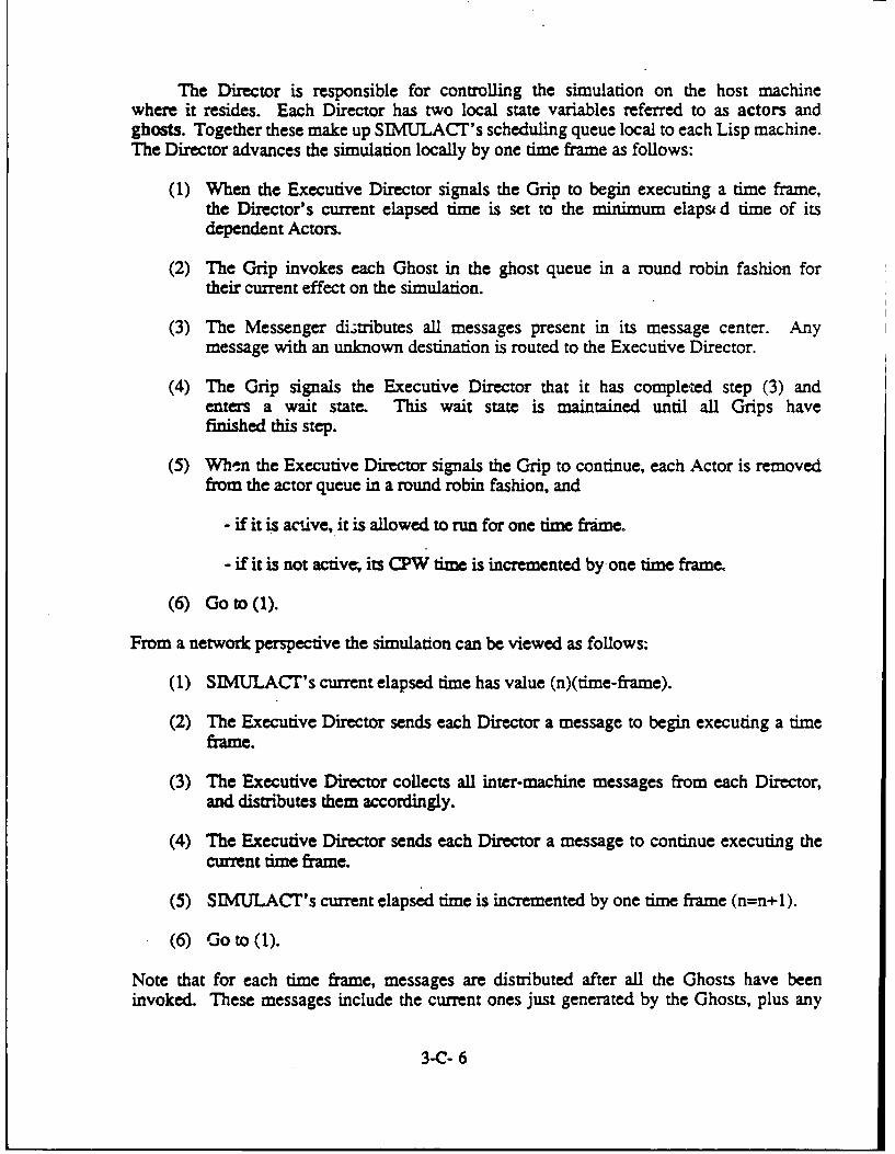
The Director is responsible for controlling the simulation on the host machinewhere it resides. Each Director has two local state variables referred to as actors andghosts. Together these make up SIMULACT's scheduling queue local to each Lisp machine.The Director advances the simulation locally by one time frame as follows:
(1) When the Executive Director signals the Grip to begin executing a time frame,the Director's current elapsed time is set to the minimum elaps d time of itsdependent Actors.
(2) The Grip invokes each Ghost in the ghost queue in a round robin fashion fortheir current effect on the simulation.
(3) The Messenger diLtributes all messages present in its message center. Anymessage with an unknown destination is routed to the Executive Director.
(4) The Grip signals the Executive Director that it has completed step (3) andenters a wait state. This wait state is maintained until all Grips havefinished this step.
(5) When the Executive Director signals the Grip to continue, each Actor is removedfrom the actor queue in a round robin fashion, and
- if it is active, it is allowed to run for one time frame.
- if it is not active, its CPW time is incremented by one time frame.
(6) Go to (1).
From a network perspective the simulation can be viewed as follows:
(1) SIMULACT's current elapsed time has value (n)(time-frame).
(2) The Executive Director sends each Director a message to begin executing a timeframe.
(3) The Executive Director collects all inter-machine messages from each Director,and distributes them accordingly.
(4) The Executive Director sends each Director a message to continue executing thecurrent time frame.
(5) SIMIJLACT's current elapsed time is incremented by one time frame (n=n+l).
(6) Go to (1).
Note that for each time frame, messages are distributed after all the Ghosts have beeninvoked. These messages include the current ones just generated by the Ghosts, plus any
3-C- 6

Actor messages generated during the previous time frame. It is the responsibility ofeach Cast member to read its mailbox in order to receive these messages, which aretagged with the time of origination. If required, the application programmer canspecify a delivery delay time appropriate for the physical system being simulated.
An example of SIMULACT's simulation strategy is depicted in Figure 2. Thesimulation consists of 6 Actors (A, B, C, D, E, F) distributed over two hosts. Duringthe first time frame, Host 1 allows Actors A, B, and C to run for one time frame each.Likewise, Actors D, E, and F each run for one time frame on Host 2. Neglecting alloverhead (including Ghosts) one simulated time frame requires three time frame units toexecute. After both machines have completed execution of the current time frame, thenext time frame begins. As the length of the time frame is made shorter, the simulationmodel can be viewed as a collection of parallel processes, each running on anindependent machine in the network. Of course, simulation using a very short time framewill increase the overhead associated with managing multiple processes running on asingle machine.
Allowable time frames in SIMJULACT may range from one sixtieth of a second toseveral seconds. The user specifies his own time frame during system initialization.For simple physical systems, SIMULACT's smallest time frame may not be long enough toexpose the inherent parallelism. However, SIMULACT is designed to simulate physicalsystems that are complex.
2.2.2 Implementation Related Details
As has been mentioned, SIMUACT "is implemented using an object orientedprogramming style. The flavor facility in ZetaLisp and similar linguistic constructs inlanguages such as CommonLOOPS and SMALLTALK (Stefik and Bobrow 1986] refer tocommunications amongobjects as bein gachieved through messagepassing. SIMULACTmakesuse of many types of ZetaLisp objects, not all of which are Actors or Ghosts. Duringthe implementation of SIMULACT, we found that it was convenient to distinguish betweenmessage exchange among flavor instances and message exchange among the Cast inSMIULACT. For this reason, we say that Cast members communicate with one another bysending and posting memos. It is the application programmer's responsibility to specifythe format of memos.
The difference between sending a memo and posting it is best explained using ananalogy from the office environment In an office environment, one worker would send amemo to one or more fellow workers to notify them of some specific information orrequest. To be sure that each worker received the memo, a copy would be placed directlyin each of their mailboxes. It is up to each worker to decide what is done with thememo (i.e., read it, lose it, or throw it away). In SIMULACT, memos are sent to themailbox associated with each Cast member. Memos are sent using a "send-memo" operationinvoked by a Cast member, and received by a "receive-memos" operation invoked by a Castmember to read its mailbox.
3-C- 7
On the other hand, if an employee had some information or a request that may bepotentially valuable to some other employees, a memo could be posted at a convenientlocation. In this case, the worker who posts the memo does not know who may see it.Though a facility for posting memos is present in SIMULACT, it is not yet clear whetherthis facility has wide application.
One difficulty with the memo facility arises when a Cast member is idle waiting foran incoming memo. It would be inefficient for S1MULACT to simulate Cast memberswaiting. To alleviate this inefficiency, we have incorporated the use of futures andthe CPW facility in SIMULACT. Futures permit Cast members to request information andcontinue processing until they cannot proceed without the requested data. The CPWfacility has been introduced as a mechanism for increasing SIMULACT's efficiency byreducing the time spent dealing with idle agents.
Futures are used in some frameworks that support the development of multiprocessorsystems, and in some parallel programming languages [Davies 1986; Halstead 1985; Rice1986; Schoen 1986]. They provide an agent with a mechanism for sending a memo thatreturns a result. A memo sent using the future facility returns a data structure calleda future. After the memo has been received and processed, the result is routed back tothis data structure. The sending agent uses this future to determine when the result isavailable, and to extract it after it has arrived.
In SIMULACr, the application programmer has two future options: future-memo andfuture-memo-wait. The future-memo operation sends a memo to a Cast member and returns afuture. The application programmer uses the functions "future-state" and "future-value"to determine when the result is available and to access it. This allows an agent toprform other tasks while waiting for a reply to a memo.
The "future-memo-wait" option is used when an agent requests information and cannotcontinue until it is received. This function alters the state of the Actor's process toreduce the overhead associated with impiementing an Actor waiting for an incoming memo.Executing this function tells SIMULACT's scheduler to increment the Actor's CPW time byone time frame each time it is scheduled to nu. Once the future has been satisfied,the Actor becomes active and will continue running beginning on the next time frame.
The controlled program wait feature gives SIMULACT the capability to speed up thesimulation by not processing Actors that are waiting. At the same time, the real timecomponent associated with each Actor is maintained. To apply this technique tosituations other then memo waiting, the "cast-wait" function is provided. Theprogrammer passes a predicate function and its arguments to cast-wait, and the CPWfacility is invoked until the predicate evaluates true.
The CPW facility can also be used with Ghosts. Executing the cast-wait functionwithin a Ghost's script function places the Ghost into CPW mode. While a Ghost is inthis state, its script function is not evaluated. Instead the predicate function passedto ,ast-wait is evaliated. Once this function evaluates true, the ghost resumes normaloperation.
3-C- 8

3. SIMULACT'S USER INTERFACE
SIMULACT provides the application programmer with a tool for simulating andinvestigating the behavior of networks of agents. Application code is written for eachagent in Lisp as though there were as many machines in the network as agents in thesystem. In this section we describe SIMULACT's user interface.
3.1 SIMULACT Initialization
SIMULACT has three initialization modes: New World Generation, Old World Load, andCurrent World Edit. The generation of a new world in SIMULACT is a menu driven processin which the application programmer specifies the details required to do thesimulation. This includes initializing the Executive Director, the Director on eachhost, and every Cast member. Once the generation of a new world in SIMULACT has beencompleted, the user has the option of saving it to disk. The Old World Load facilityautomatically loads this information into SIMULACT, without involving the user. TheCurrent World Edit option loads an old world into SIMULACT, and then allows the user toedit it. This is a convenient method for running subsequent simulations with minoralterations.
3.2 Executive Director and Director nitialization
Initializing the Executive Director configures the Lisp-machine network and sets upthe user interface. The user must specify the number of hosts involved in thesimulation, and set such parameters as the time frame size and the simulated starttime. This allows SIMULACT to initialize the gauge facility, which is that part of theuser interface which provides control over the simulation (mode select gauge), displaysthe current simulated time (elapsed time gauge), and allows the application programmerto monitor domain specific characteristics. The initialization of the ExecutiveDirector is not complete until all Directors are initialized.
Director initialization is done locally at each host and includes initializing theCast and their environments. After each Cast member is initialized, the Messenger makesan entry into its "address-book". The address-book is an association list linking aCast member's stagename to its corresponding Lisp object, and is used to route memos.Director initialization also alters the host machine's operating system to accomodatethe specified time frame size.
3.3 Cast Member Initialization
Each Cast member runs in its own package [Steele 1984], so it cannot directlyaccess any other Cast member's local state. This ensures that all communications amongCast members are directed through SIMULACT. Each Cast member has one or moreinitialization files associated with it. These files contain code written by theapplication programmer describing all activities performed by the Cast member. The Castmember's script function must be contained in this code.
3-C- 9

Each Cast member is given a stagename during initialization. As has beenmentioned, these stagenames are used by the Director's Messenger in routing memos. Eachcast member is also associated with a window pane on the console's screen duringinitialization. The typical user interface functions (i.e., print, read, etc.) areshadowed so that the user can access each cast member easily through these windows. Thecollection of all Cast panes makes up the Director's window frame. SIMULACT's interfaceallows the user to display one Director frame at a time. It also notifies the user whena deexposed frame needs attention.
Since each Cast member maintains its own independent local state, multipleinstances of the same Cast type can lead to multiple copies of code. To reduce thiscostly overhead SIMULACT allows Cast members to use Support packages.
3.4 Support Packages
A Support package contains code that can be accessed by several Cast members, thusreducing memory requirements. As in any shared memory system, a problem could arisewhenever a Support package accesses or alters global information. The underlyingassumption concerning independent environments for each Cast member would be violated.To guard against these problems, SIMULACT automatically detects their potentialoccurrence and warns the user when a Support package tries to instantiate a globalvariable. Ideally, Support packages should contain purely functional code. However,this restriction would severely restrict the amount of code that can be placed intoSupport packages.
There are two ways to use Support packages other than for purely functional code.One way is for a Cast member to pass a local data structure as an argument to a Supportpackage function. If that function is "for effect", the result could then be boundappropriately. The other method requires the application programmer to use SIMULACT's"sim-set" function. Basically, the sim-set function allows the Support package to altera global variable that is present in each of the Cast packages. The goal of the Supportpackage facility is to reduce simulation overhead. Use of support packages does reducethe overhead, but it does so at the expense of requiring that the user have moreknowledge about SIMULACT's implementation than is desirable.
4. CONCLUDING REMARKS
In this paper, we have described SIMULACT, a generic tool fr, simulating andobserving the behavior of networks of distributed processing agents. This system iscurrently running as one component in a testbed for investigating problems indistributed artificial intelligence. Our current network configuration contains threeLisp machines.
The system has been particularly useful as a tool in the development of adistributed planning system [Conry, Meyer, and Lesser 1986]. It has been used to exposethe nature of message traffic in this planner and to develop and debug plan generationin a distributed environment. SIMULACT is also being used as an aid in the development
3-C- 10

of a distributed diagnosis system. We have found that its modularity and transparencypermit us to concentrate on the development of agents which exhibit the desiredcharacteristics rather than on the problems associated with managing the distributedenvironment.
Acknowledgments
The Authors would like to express their appreciation for the contributions of theircolleagues Robert Meyer and Janice Searleman. Their suggestions and support have beeninvaluable. This work was supported in part by the Air Force Systems Command, Rome AirDevelopment Center, Griffiss Air Force Base, New York 13441-5700, and the Air ForceOffice of Scientific Research, Boiling AFB, DC 20332 under Contract No.F30602-85-C-0008. This Contract supports the Northeast Artificial IntelligenceConsortium.
REFERENCES
Brown, IL, C. Tonge, and G. Foyster. 1983. "Palladio: An Exploratory Environment forCircuit Design," IEEE Computer (Dec.): 41-56.
Conry, S. E., R. A. Meyer, and V. R. Lesser. 1986. - "Multistage Negotiation inDistributed Planning", University of Massachusetts, Amherst Massachusetts 01003, COINSTechnical Report 86-67 (Dec.).
Davies, B. 1986. "CAREL: A Visible Distributed Lisp." In Proceedings of the ExpertSystems Workshop (Asilomar, Pacific Grove, CA., Apr. 16-18). DARPA, 171-178.
Delagi, B. 1986. "Care User's Manual," Knowledge Systems Laboratory, Department ofComputer Science, Stanford University.
Durfee, E. 1984. "A Parallel Simulation of a Distributed Problem Solving Network." M.SThesis, Electrical and Computer Engineering, University of Massachusetts at Amherst.
Halstead, R.H. 1985. "Multilisp: A Language for Concurrent Symbolic Computation." ACMTransactions on Programming Languages and Systems 7, no. 4 (Oct.): 501-538.
Hewitt, C. 1986 "Concurrency in Intelligent Systems." Al Expert (Premier): 44-50.
Lesser, V.R. and D.D Corkill. 1983. "THE DISTRIBUTED VEHICLE MONITORINGTESTBED: A Tool For Investigating Distributed Problem Solving Networks." The AIMagazine 4, no. 3 (fall): 15-33.
Misra, J. 1986. "Distributed Discrete-Event Simulation." ACM Computing Surveys 18, no.I (Mar.): 39-65.
3-C- II

Moon, D.A. 1986. "Object-Oriented Programming with Flavors." In O OPSLA'86 ConferenceProceedings (Portland, OR., Sep. 29 - Oct. 2). ACM, Baltimore, MD., 1-8.
Rice, 3. 1986. "Poligon, A System for Parallel Problem Solving." In Proceedings of theExpert Systems Workshop (Asilomar, Pacific Grove, CA., Apr. 16-18). DARPA, 152-159.
Schoen,E. 1986. "TheCAOS System. "KnowledgeSystemsLaboratory,DepartmentofComputer
Science, Stanford University, Report no. KSL-86-22 (Mar.).
Steele, G.L 1984. Common LISP. Digital Press, Burlington, MA.
Stefik, M. and D.G. Bobrow. 1986. "Object-Oriented Programming: Themes and Variations."The Al Magazine 6, no. 4 (winter): 40-62.
3-C- 12

DIRECTOR
ACTOR GHOST GHOST
E n I I m
a) Host Level Structure
EXECUTIVE DIRECTOR
DIRECTOR I DIRECTOR 2
b) Network Level Structure
Figure I SEMULACT's Simulation Structure
3-C- 13

HOST 1 HOST 2
A 0tul -. . .. Tr17e
B E Framet=2 . .. .. .. . 1
C Ft-3--
A 0t=4 i Tme
B C Framet-5 . .... 2
t"6 "--....
A 0t=7 Tme
8 E Framet-8 -- -- 3
t"9 - - C -
Figure 2
3-C- 14

THE ROLE OF KNOWLEDGE-BASED SYSTEMS IN
COMMUNICATIONS SYSTEM CONTROL
by
Robert A. MeyerElectrical and Computer Engineering
Clarkson UniversityPotsdam, New York 13676
and
Charles MeyerRome Air Development Center, DCLD
Griffiss Air Force BaseNew York 13441-5700
Abstract
The role of knowledge-based systems in communications system control is presented inthis paper as a collection of distributed, multiple agent systems serving as intelligentadvisors to human controllers. Based on an analysis of system control functions, andinterviews with field personnel, we describe a model for communications system controlin the Defense Communications System. Using this model we have designed an architecturefor a diversely distributed, multiple agent, knowledge-based system. A simulationtestbed has been implemented to support experimental development and testing of thecomponents of this architecture in a network of Lisp machines.
3-D- I

Introduction
The purpose of this paper is to describe one role which knowledge-based systems mayplay in the future control of the Defense Communications System (DCS). The workdescribed here is based on the completion of the first phase of a five year researchprogram designed to answer fundamental questions about the use of knowledge-basedsystems in communications network management and control. We have developed anarchitecture for a diversely distributed, multi-agent system in which each component isa specialized and localized knowledge-based system designed to provide assistance to thehuman operator and to cooperate with similar such systems performing other functionsand/or located in physically separate facilities. This view of the role of aknowledge-based system as a collection of autonomous, cooperating independentspecialists is an important characteristic of our approach to network management andsystem control for the DCS in the future.
Modem communications systems, such as the DCS, are highly complex collections ofequipment and transmission media which currently require, in varying degrees, humanintervention for control. The control task is one which requires extensive, specializedknowledge and the ability to reason using this knowledge in solving problems. In thepast, system control has been a difficult area to automate because the number ofsituations which may arise and alternative solutions available are very large, and thustraditional, purely algorithmic approaches have been found lacking.
In this paper we first describe a model for communications system control, based onthe DCS in Europe, and identify specific control tasks needed in this environment. Wefind three fundamental kinds of knowledge-based problem solving activities are required:(1) data interpretation and situation assessment; (2) diagnosis and fault isolation; and(3) planning to find and allocate scarce resources for restoral of service in the eventof an outage. In addition to this functional distribution of problem solvingactivities, our model requires a spatial distribution of control as well. We present anarchitecture designed to meet these requirements which consists of a distributedknowledge-based system built on a community of problem solving agents. Each agent is afunctionally specialized knowledge-based problem solver at a specific site. Theseagents coordinate and cooperate to solve global problems among themselves, crossingfunctional or spatial boundaries as required.
The reason for s~udying distributed problem solving lies in the observation thathumans often rely on teams of people to solve complex problems. Within a team there isusually a division of labor so that each member of the team is a specialist on some partof the problem. Each of these specialists has only a limited perspective about theoverall problem, and each finds that he can only deal with those aspects of the problemfor which he is responsible through cooperation with others on the team.
Distributed arificial intelligence is concerned with problems that arise when agroup of loosely coupled problem solving agents works together to solve a problem [1].These agents have characteristics that closely parallel those mentioned above:
3-D- 2

functional specialization, local perspective, and incomplete knowledge. Each agent usesits own local perspective in performing its tasks, though it may have a need for someknowledge about another agent's local perspective.
At the present time a testbed has been implemented which supports simulation ofmultiple agents on one or more physically distinct Lisp processors. Detailed design andimplementation of specific agents is in progress. We believe the paper has two chiefcontributions to make at this time. First, based on in-depth problem domain analysis,including field site visits and interviews with operating personnel, we have identifiedspecific problem solving tasks which we believe are suitable for a knowledge-basedsystem. Furthermore, our design for this system incorporates new ideas in distributedproblem solving: specifically, a diversely distributed problem solving architecturewhich supports coordination and cooperation among functionally and spatially distinctagents.
The Communicatons System Control Model
In our investigation of knowledge-based systems for communications system control,we have concentrated on the European Theater of the DCS. The DCS is a large, complexcommunications system consisting of many component subsystems. It provides thelong-haul, point-to-point, and switched network communications for the Department ofDefense. We have chosen the European Theater for several reasons. The DCS networkstructure in Europe is particularly interesting for the study of distributed problemsolve paradigms. It consists of a large number of sites (about 200) which areinterconnected in an irregular structure. It is currently controlled by closecooperation and coordination among a group of highly skilled human controllersdistributed throughout the system. The wide variety of transmission media andcommunications equipment in use has given rise to the need for sophisticated problemsolving tools to assist these human operators in providing the best possible (control ofthe system.
A careful analysis of the DCS reveals that it must be viewed from a multidimensionalperspective. The overall organization of the DCS is layered, consisting of three basiclayers: transmission facilities, circuits and networks. Each of these layers may befurther subdivided into component subsystems. Transmission facilities may be eitherterrestrial or satellite. Terrestrial transmission is based on either analog or digitalchannels, multiplexed into groups or digroups, and then into supergroups which aretransmitted over communications links from one station to another. The most commontransmission medium used is line-of-sight (LOS) microwave; however, there are alsotropo-scatter, fiber optic, and cable links used. Satellite transmission facilities arealso used, primarily for transoceanic links.
The transmission facilities form the backbone structure over which the second layer,consisting of circuits and trunks, is built. These are predominately dedicated circuitsbetween users. Circuits may traverse several stations following fixed paths. There area number of key data items which are associated with each individual circuit or trunk
3-D- 3

and which are important in the performance of system control. These include the userpriority level, the restoration priority, and the quality of service required.
Networks form a third layer of the DCS organization. There are three generalcategories of networks: circuit switched voice, packet switched data, and dedicated orspecial purpose networks. These networks rely on trunks provided by the transmissionsubsystems to interconnect the switches.
Another perspective of the DCS is equipment oriented. The DCS consists of a verylarge inventory of communications equipment, such as modems, multiplexers, radios,switches, etc. Each equipment item has certain distinguishing characteristics includingits function within the overall system, its status signals (which may be monitored andmade available to system controllers), and its control capabilities (which provide themechanism for implementing desired control actions on the system). Knowledge aboutequipment is vital to problem solving agents attempting to control the system, and cutsacross the layered organization described above. For example, a particular multiplexermay be a part of a transmission facility, as well as a part of one or more circuits, anda part of one or more networks.
The final dimension along which the DCS may be analyzed is its organization formonitoring and control. Data is collected in real-time or near real-time at each siteabout the operating state of the equipment at that site and about the quality of signalsbeing transmitted to the site. In a completely centralized control ;ystem, this datawould be transmitted to a single control center for interpretation by the systemcontrollers. However, our model .of the DCS is based on the concept of a distributedcontrol system, in which certain sites are identified as either sub-region, region, orarea controi centers. Each control center has primary responsibility for a subset ofthe other sites within some geographic neighborhood. Each control site receives datafrom the sites within its region of responsibility.
Why are we interested in a distributed control system? The primary reason is thatsuch systems are inherently more robust and survivable in the presence of equipmentfailures or externally applied threats. Total reliance on a centralized control sitewould mean a total loss of system control in the event of a complete failure at or lossof the central site, or in the event of isolation of that site from the rest of thesystem. Partitioning the system into regions is also an advantage in that the controlproblem may be made modular, and thus easier to solve. Local problems (ones which ariseinternally to a region and have no impact outside the region) may be solved within thelocal region, and do not become visible to the other regions.
In accordance with the future plans [2] of the Defense Communications Agency (DCA),the DCS system control is to be organized in a five level hierarchical structure.Beginning at the lowest level and moving up, each level in this hierarchy represents abroader view of the DCS, a larger geographic area, a greater responsibility and a higherauthority. Level 5 (the lowest level) represents stations or facilities at which eithera technical control or patch and test capability exists, or an access switch exists, oran earth terminal for a satellite link exists. Level 4 represents either a major
3-D- 4

technical control facility or nodal switch. Level 3 represents a subregion controlcenter (SRCF). Level 2 corresponds to theater level control and may be either an areacommunications operations center (ACOC) or alternate ACOC. Level I is the worldwideDefense Communications Agency Operations Center (DCAOC). For the purposes of thisdiscussion, we are concerned with level 3 and lower levels. These are the levels mostclosely associated with the real time or near real time control of the system. Withinthe European theater approximately 13 SRCFs are expected to be established. Thus, it isat this level (level 3), or lower, that the need for cooperative problem solving islikely to be the greatest.
System Control Tasks
System control is defined [3] as the process "... which ensures user to user serviceis maintained under changing traffic conditions, user requirements, natural or manmadestresses, disturbances, and equipment disruptions on a near term basis." System controlincorporates five major functions: facility surveillance, traffic surveillance, networkcontrol, traffic control, and technical control. Each of these functions will bedescribed in more detail and related to specific problem solving activities.
Three distinct problem solving activities have been identified within the five majorfunctions of system control. We refer to these activities as performance assessment(PA), fault isolation (FI), and service restoral (SR). A general task description foreach of these is given below and related back to one or more of the five functions ofsystem control.
Performance Assessment (PA)
Performance assessment may be viewed as a problem in data interpretation andsituation assessment. Since data is available only on a distributed basis, coordinationmust take place among the PA agents in order to arrive at a coherent view of the stateof the communications system. The facility surveillance and traffic surveillancefunctions of system control are included within the PA activity. Real time equipment,transmission network, and traffic data are measured and collected to provide thecontroller with the information needed to determine the status of the transmissionsystem and facilities, the quality of communications circuits and network performance.Trouble reports from users are also significant inputs to this activity.
The goal of PA is to formulate a local view of system status and performance, and toidentify as quickly as possible the impact of any observed deviations from normaloperating conditions. The PA agent is responsible for determining the need to invokeeither fault isolation and/or service restoral agents. Since few problems are likely tobe localized within the area of responsibility of a single SRCF, the PA agent must alsocommunicate with similar agents in neighboring areas to arrive at a consistentassessment of status throughout the system.
3-D- 5

Fault Isolation (FI)
The fault isolation task is a diagnostic activity. It is concerned with identifyingthe specific cause and location of faults within the communications system. The term"fault" is used in a very broad sense to mean either a complete outage of service or adegradation in quality or performance. The F1 agent responds to reports of known orsuspected faults determined by PA. Much of the same data available to PA is also usedin the FI activity, however the analysis is carried out in greater depth, and thecause-effect relationship is emphasized. In some instances the immediate results of F1may be inconclusive and will require additional testing to resolve ambiguities in thedata. The FI agent should be able to direct the initiation of automatic test functionswhere such functions are available. Knowledge about specific equipment types, themeaning of test results and the current subsystem state are all used by Fi to infer theprobable cause of the failure.
The FL agent incorporates the in-depth analysis aspects of facility and trafficsurveillance as well as the testing aspects of technical control Coordination andcooperation with similar agents at intermediate or distant end stations involved in afaulty link, trunk, circuit, or network are often necessary to determine the cause andlocation of a fault.
Service Restoral (SR)
Service restoral is a plan generation and selection activity which recommends a setof specific control actions needed to restore user service. These actions may involvealternate routing of trunks or circuits, switch control (such as code cancellation, codeblocking, modification of routing tables, etc.), or transmission system configurationcontrol (such as reallocation of equipment, use of backup or spare equipments, etc.).The network control, traffic control, and some aspects of the technical controlfunctions are encompassed in the SR activity.
System Architecture
The system architecture which we describe has been designed to support multipleproblem solving agents distributed both functionally and spatially. This discussionaddresses three primary facets of the architecture: (1) the role of this distributedknowledge-based system in the context of human network controllers in the DCS; (2) thestructure of the intelligent system residing at each node; and (3) the overall structureof the distributed problem solving system as it is incorporated in the simula:iontestbed.
Any knowledge-based distributed probLm solving system actually incorporated in theDCS field environment would be most accurately viewed as an intelligent assistant to thesystem controllers. It would perform the tasks of filtering the data received, andanalyzing and interpreting it as well. Based on these interpretations, it would suggestalternative restoral plans and advise the humans as to which equipments are probably
3-D- 6

malfunctioning and what control actions might be appropriate. The human operator wouldhave the responsibility of directing service restoral, dispatching service personnel,and initiating control actions. In addition, the human retains the privilege ofpreempting the system at ary time. As an intelligent assistant, the system wouldrelieve the controller of many tedious tasks. It would also provide a vehicle fortraining activity that can be utilized by new personnel
As the discussion in the previous section indicates, several modes of problemsolving must be performed at each site corresponding to a control facility of thecommunications system. Performance assessment is an ongoing data interpretation andsituation assessment task. Fault isolation is a diagnostic activity and is initiatedwhen PA has determined the possible existence of an equipment failure. Service restoralis a plan generation task, and is also initiated by PA. T se tasks ire relativelyindependent and may be active concurrently; however, they must share the same base oflocal knowledge concerning the status of the communication system and its expectedbehavior. An implicit assumption is that each control site only maintains detailedknowledge about the communications equipment and circuits which are within its region ofresponsibility. Our node architecture represents a decomposition of nodal problemsolving activity into these three primary tasks and assumes the local knowledge basecontains only very limited knowledge about the system outside the local area.
The structure of this architecture for distributed problem solving reflectsdistribution in two dimensions. At a local level, the system is seen as a number offunctionally specialized agents that cooperate in a loosely coupled fashion. Theseagents comprise a local participant in a network-wide team of problem solvers. At theglobal level, the system may be viewed as a group of relatively independent, spatiallydistributed problem solving systems cooperating to solve a collection of problems. Oneof the systems is composed of the group of fault isolation agents. The fault isolationagent at each node cooperates with its counterparts at other nodes in solving the faultisolation problem for the communications system. In a similar fashion, the servicerestoral and performance assessment agents may be regarded as distributed problemsolving systems in their own right.
An important feature of this architecture is the concept of a local, sharedknowledge base. Although each problem solving agent has its own, private knowledgeabout how to perform the specialized problem solving activity for which it isresponsible, much of the knowledge needed for problem solving is related to thecommunication system. This knowledge describes the network structure and organization,the details of different equipment types, and what is known about the current state ofthe communications system. Since this knowledge is spatially distributed, and sharedamong the other functional agents at the same local site, it is implemented as a singlelocal knowledge base. The details of knowledge representation and structure of thisknowledge base have been presented elsewhere, (4] and will not be repeated here.Suffice it to observe that since this knowledge base contains dynamic information, andis shared by multiple, independent agents, some sort of access control is necessary.This is provided in the form of the knowledge base manager.
3-D- 7

The knowledge base manager serves as an intelligent interface agent between theknowledge base and the three primary agents, PA, FT, and SR, which are operatingconcurrently. The knowledge base manager embodies knowledge about the local knowledgebase itself. For example, it knows the limits of that knowledge base in the sense thatif a query for information is made which requires knowledge not locally available, theknowledge base manager issues a message requesting the information from an appropriatedistant node(s). The knowledge base manager is also knowledgable about the timesensitivity of some parts of the local knowledge base and is thus able to makeintelligent (as opposed to arbitrary) decisions in controlling concurrent requests foraccess. Finally, the knowledge base manager has the responsibility for maintainingconsistency in the local knowledge base. In order to petform these functional tasks,the knowledge base manager may be viewed as an agent having meta-level knowledge.
The local architecture thus consists of four knowledge-based components, cooperatingon a local basis to maintain an informed state of awareness about the local operatingconditions. This is shown in Figure 1 below.
Performance Fault Isolation Service RestoralAssessment
Knowledge Base Manager
LocalKnowledge Base
Figure 1. Control node architecture
Interagent communication is supported in the form of simple messages called memos. Amemo may be sent to one or several recipients and may be a request for information or anaction to be taken, a response to a previous request or some unsolicited informationshared by an agent with others. Additional components not shown in above diagram arethose which interface with the external world, such as interaction with the operator,and real-time data collection.
3-D- 8

Concluding Remarks
A generic simulation testbed, SIMULACr, has been implemented [5] to supportexperimental testing and evaluation of alternative design approaches for thedistributed, multiple agent knowledge-based system described here. This testbed willbecome a tool for investigating a number of significant issues in the design ofcooperative, distributed problem solvers. The goal of this research is to develop abetter understanding of the fundamental problems which arise in building a distributedproblem solving system. We believe the problem solving environment demanded by thecritical need for defense communications under a wide variety of stressful conditions ismost likely to be satisfied by a distributed, knowledge-based system, and thus theresults of our research should provide guidance in meeting this need in the future.
Acknowledgments
This work was supported in part by the Air Force Systems Command, Rome AirDevelopment Center, Griffiss Air Force Base, New York 13441-5700, and the Air ForceOffice of Scientific Research, Boiling AFB, DC 20332 under Contract No.F30602-85-C-0008. This contract supports the Northeast Artificial IntelligenceConsortium (NAIC).
References
1. Davis, R. and P.G. Smith, "Negotiation as a Metaphor for Distributed "oblemSolving," Artificial Intelligence, VoL 20, pp. 63-109. Jan 1983.
2. "Defense Communications System Control Plan (Europe)," Defense CommunicationsAgency. Sept 1984 (draft).
3. "DCA Circular 310-70-1", Vol I, II, and MII, Defense Communications Agency.4. Conry, S.E., R.A. Meyer and .E. Searleman, "A Shared Knowledge Base for
Independent Problem Solving Agents," Proc. of the Expert Systems in Government Symp.McLean, VA. Oct 1985.
5. MacIntosh, Di. and S.E. Corny, "SIMULACT: A Generic Tool for SimulatingDistributed Systems," Eastern Simulation Conference. Orlando, FL. April 1987.
3-D- 9

MACHINE INTELLIGENCE FOR
DoD COMMUNICATIONS SYSTEM CONTROL
by
Gerald Michael Adamsand
Charles N. MeyerDCLD/ Rome Air Development Center
Griffiss Air Force Base, NY 13441
Robert A. MeyerElectrical and Computer Engineering Department
Clarkson UniversityPotsdam, NY 13676
Abstract
Modem military communication systems are complex, multi-layered networks whichdemand an integrated and automated approach to network management and system control.Effective system control requires interpretation of operating data to assess networkstatus, planning to reconfigure network resources in the event of outages, and decisionmaking to effect appropriate control actions. To meet these needs, the U.S. Air Force,in conjunction with the Defense Communications Agency (DCA), is investigating the use ofmachine intelligence techniques to provide real-time expert assistance to the humanoperators responsible for the management and control of the Defense CommunicationsSystem. This paper describes an evolutionary approach to the development of theseintelligent assistants, in which modular hardware and software systems are beingdeveloped and tested in an incremental progression of closely coupled projects.
3-E- I

1. Introduction
1.1 The Defense Communications System
The Defense Communications System (DCS) is the primary long-haul communicationssystem for the U.S. military forces. It embodies both Government owned and leasedfacilities within the U.S. and abroad. These facilities encompass a wide range ofnetworks, including direct dedicated lines, and circuit, message and packet switchednetworks. The DCS provides both voice and data communications services at multiplelevels of security. As a result of continuing efforts to improve the quality andreliability of service, the DCS consists of a large variety of equipment types, spanningtechnologies from basic analog systems, such as the low data rate voice channelteletypes, to modern digital statistical multiplexers.
The DCS consists of stations interconnected by links. Each station has of acollection of communications equipment, typically associated with a group of localusers, for example at an airbase. Of course some stations have no local users, butserve as repeaters or relay stations, or as switching centers. Each link represents thetransmission medium interconnecting two stations, such as a microwave radio channel, asatellite channel or cable. This station/link model of the DCS represents only thefirst "layer" - the transmission subsystem - in a multi-layer structure. Thetransmission layer is the base upon which other networks are constructed. For example,AUTOVON is the worldwide circuit switched voice network for the military. The long-haulinterswitch trunks needed for AUTOVON are provided by the transmission subsystem.
The management and control of this complex communications system is clearly animportant task. We rely heavily on fast, secure, high quality communications bothduring peace time and during conflict. We have come to expect near 100% availabilty ofcommunications resources. The job of providing the management and control of theseresources to meet these expectations is called Communications System Control.
L2 Communications System Contirol
The objective of system control is to maintain end-co-end user communicationsconnectivity under a variety of adverse conditions. These range from routine minorequipment malfunctions to major destruction of facilities due to hostile actions.Effective communications system control requires managing network and transmissionresources so as to make the best utilization of available assets given the priorities ofthe current context. It should be emphasized that this is a very dynamic environmentsince actions external to the communications system may bring about significant changesin traffic loading and priority of users.
Currently, the structure of this control system consists of two complementaryparts. The transmission subsystem is predominately controlled in a decentralized mannerfrom tech control facilities (TCF) distributed throughout the network. Each TCF isstaffed on a 24 hour basis by highly trained military personnel known as "tech
3-E- 2
controllers". Generally TCFs are located outside the United States, since within theU.S. the transmission subsystem is leased from common carriers, and is not under directgovernment control. Networks, such as AUTOVON or DDN (the Defense Data Network), arecontrolled from centralized control centers. These are either the Area CommunicationsOperations Center (ACOC) in the European and Pacific theaters, or the DCA OperationsCenter (DCAOC) in the U.S. There is a strict hierarchical relationship among thesecontrol system elements; the DCAOC is at the top, having a worldwide view, the ACOCseach have a theater-wide view, and each TCF has a local perspective.
There are important changes being made to this current structure. The objectivecontrol structure for the future DCS incorporates the concept of a subregion and asubregion control facility (SRCF) [1]. The SRCF is intended to distribute the conrolcapability of the various networks thus providing a more survivable control system. TheSRCF is also expected to collect transmission subsystem monitoring data remoted fromseveral TCFs and assume some degree of transmission control. The SRCF thus provides amix of both distributed and centralized control and management capabilities. The SRCFwill also provide die means for integrating transmission monitoring and control andnetwork management functions.
1.3 Functional Requirements
In this section we examine, at a high level, the functions required to achieve theobjectives of communications system control We will use the term "system controler"in a generic sense to mean any combination of one or more humans and machinescollectively charged with the responsibility for achieving the system controlobjectives.
First, the system controller must form an assessment of the current global networkstatus. This involves interpretation of data collected from throughout the network andcorrelation of information from disjoint or dissimilar sources. For example, a linkfailure in one part of the network might have a major impact on the traffic loading of aswitch in another part of the network. Under normal conditions this additional loadingmight not be criticaL However, if other conditions (perhaps completely external to thecommunicatons system) were also contributing to an increased traffic load at this sameswitch, then a control action might be necessary to prevent an overload situation.Recognition of this relatively simple situation requires interpreting both transmissionalarm dam and switch traffic dam, assessing the impact of the link failure, andcorrelating this conclusion with the assessment of the current switch condition.
A second functional requirement for the system controller is to formulate plans foralternative actions which would alleviate problem situations of the type describedabove. Planning is the primary function which attempts to make the best utilization ofavailable communications assets.
A third requirement is for a diagnostic capability. While assessment recognizeschanges in network status, and planning provides alternatives to alleviate problems, alonger term solution must be sought which attempts to diagnose the cause of the problem,
3-E- 3

so that it may be corrected. In many cases diagnosis is simply a matter of tracingcircuit paths until the faulty equipment is located. However, it is not always sosimple. Often a faulty circuit may traverse one or more segments in which no alarms orother indications of failure are present. Another complicating factor is thepossibility of multiple faults, some of which may mask others. Diagnosis requirescareful reasoning from the known set of alarms and measured data, an understanding ofthe functional differences in each of the various equipment types, and knowledge aboutthe network interconnection structure.
1.4 Summary
The next section describes the nature of system control problems which currentlyexist or may be anticipated in the future. Section three is a synopsis of the currentprograms in the evolutionary approach being pursued by the Rome Air Development Center.These programs are seeking engineering applications of machine intelligence to systemcontrol problems. In section four we provide a rationale for the use of machineintelligence as opposed to other, more traditional methods. Concluding observations aremade in section five.
2. Problem Description
This section describes the system control problem in two distinct time frames: (1)the current and near-term context, and (2) a long-term context. In the near-term thereare two major changes taking place which are having a significant impact on the abilityof the various military departments to provide the highest quality tech control Theseare a rapidly changing telecommunications technology and an erosion of the supply ofsenior manpower. The impact of these changes is described in section 2.1. For thelong-term, system control will be most influenced by the implementation of these newtechnologies currently planned for the near-term and by the changing structure of thecontrol system itself. These issues are addressed in section 2.2.
2.1 Near-term Problems
At present, system control is almost entirely a manual operation. Tech controllershave some automated equipment monitoring and automated test capability, but they do nothave any automated support for fault isolation and diagnosis functions. A typical TCFmay have 1000 or more circuits which either traverse or terminate at the local station.In addition, the tech controller may have responsibility for equipment at a remote,unmanned relay station. The current "data base" upon which the tech controller dependsfor detailed information about these circuits is a card file. Each card has the circuitdata on one side, and often has a schematic diagram of the circuit on the reverse. Muchof the expertise needed to identify and diagnose problems with circuits traversing olderequipment resides only in the experience of the senior tech controllers.
The rapid change in telecommunications technology has resulted in modernizaiton ofstation equipment at a much greater pace than can be matched by tech controller training
3-E- 4

programs. The impact of this is that the "new" tech controller needs more on-the-joblearning. Typically, this means the new controller learns about the operation and faultdiagnosis procedures for sophisticated digital communications equipment only when aproblem arises. Since the reliability of these equipments is usually quite good, theopportunities for on-the-job training are few and infrequent. Given the sophisticationof some of these devices, it is simply not realistic to expect tech controllers tobecome expert in a short time period under these conditions.
The training problems are only exacerbated by an erosion of the senior techcontroller manpower supply. The rapid growth of the commercial telecommunicationsindustry has placed a premium on the skills possessed by military tech controllers. Asa result these people are given significant economic incentives to leave the militaryfor private industry at about the same time they are just beginning to become fullytrainedL Thus the pool of senior, "expert" tech controllers is dwindling.
2.2 The Long-term Environment
As the transition to an all digital system becomes complete, the nature of systemcontrol will also change. At the lower levels, individual equipments will incorporatemore than simple built-in test capability and will include diagnostic capability aswell, thereby allowing self-identification of failed units at the replacement unitleveL The incorporation of automated digital patching systems (called DPAS, forDigital Patch and Access System) will allow an entirely different, and more responsive,approach to circuit restoration when outages do occur.
The changing control structure will also have an impact on system control problemsand how they are solved. Perhaps the most significant of these changes is theintroduction of the SRCF and the potential for correlation of monitored data andintegration of control actions across transmission subsystems and networks. To takeadvantage of this situation, system controllers must have a broader scope of expertise.In this new environment, a system controller should be able to recognize a problem whicharises in one parr of the system, and predict the impact on the global system of variousnetwork or transmission control actions taken to alleviate this problem.
The combination of improved on-line monitoring, remote reporting of alarms to acentral point within a subregion, and the need for correlation of data from bothtransmission subsystems and networks presents a problem of potential informationoverload for the human controller at the SRCF. During a major outage the volume of databeing sent to the SRCF which the controller must examine, interpret, and act upon is toomuch for human decision making. Along with this, the controller has many alternativecorrective actions which must be considered within this dynamic context. These factorsmake an accurate and timely assessment difficult for the human controller. It seemsmost unlikely, given the current problems with senior level manpower retention, that thefunctional requirements for system control could be adequately met by human controllersalone.
3-E- 5

Another major challenge for system control in this longer term environment is toachieve an appropriate balance between distributed and centralized control. The SRCFhas been introduced in recognition that survivability of network management can only beachieved by distributing the potential for network monitoring and control to severalstations instead of concentrating it at a single, vulnerable site. However,distribution introduces new problems concerned with maintaining global coherence amongthese distributed controllers. An important question to be addressed is how mightdistributed control facilities (such as the SRCFs) work in a cooperative manner for thebenefit of the system as a whole?
3. Evolutionary Approach
3.1 Background
The problem of designing and implementing an effective control system for acomplex, evolving communications network is not new. The U.S. Air Force has had priorexperience in at least two related projects. In both cases, an attempt was made todesign a single, complete, fully automated control system as one major engineeringeffort. In both cases the products fell short of expectations. A major factor in bothcases was the need from the control system designer's perspective to completely specifyeverything in advance while the target system was still evolving and thus could not befully specified. The modular, evolutionary approach currently being followed isintended to avoid these same problems again.
3.2 Modu!s- Developmert
The key aspect of this evolutionary approach is the development of incrementalimprovements in system control capability through a series of modular hardware/softwaresystems. For example, previous work has already developed an automated transmissionmonitoring and control system (TRAMCON). While this represents only a "bare bones"degree of automation, it provides an essential service which "an be used by woreadvanced systems which will come later. Similarly, as automated test systems arecurrently being developed, these too may be used by more advanced systems of the futureas low level "extension tools" to test circuit segments suspected of degradation orfailure. One of the benefits of this modular development is the usefulness of each ofthese additional systems. Since each new module is designed to provide an importantfunctional capability independent of subsequent developments, failures or problems withmore advanced systems do not disable the lower level modules.
A modular development approach offers other advantages as well. For example, itallows flexibility in adapting to changing system requirements. As each new modularcomponent is developed, tested, and placed in the field, valuable feedback may begathered from both the developers and the users which enhances the performance ofsubsequent components.
3-E- 6

Another, pragmatic reason for a modular development process is budgetary.Traditionally communications systems rank behind weapon systems in seeking the attentionof military and civilian budget planners. Funding for large, "do it all at once"programs is simply not available under present budget constraints. In particular,research involving the application of machine intelligence techniques, which isadmittedly a high risk development area, must proceed by a carefully controlled sequenceof demonstrably successful projects.
3.3 The Expert Tech Controller
The first system to be developed in this modular approach is an expert system toprovide assistance to a tech controller in performing fault diagnosis. This system isintended to address the near-term system control environment. The initial version hasbeen designed and implemented by Lincoln Laboratories and is described in detail inanother paper in this session [2]. The objective of this effort is to capture theexpertise of the most knowledgeable, senior tech controllers, and then build aknowledge-based system which could guide a less-skilled controller through a faultdiagnosis procedure with the same proficiency as the senior "expert". The system wasdeveloped with the full cooperation of the TCF staff at Andrews Air Force Base, MD, andhas been installed experimentally there since December, 1986. Initial reaction by TCFfield personnel has been favorable.
Using the expert system building tool, ART, from Inference Corporation, Lincoln Labresearchers were able to quickly construct prototype versions which were thendemonstrated to the expert tech controllers. These tech controllers provided valuablefeedback on both the accuracy and useability of each successive version. The result isa system which incorporates both rule-based and procedural programming paradigms andemphasizes a natural human interface based on graphically displayed circuit diagrams.
3.4 Knowledge-based Control For The Defense Switched Network
The second project addresses system control needs at the boundary of near-term andlong-term environments. The Defense Switched Network (DSN) is a circuit switched voicenetwork designed to replace the older technology AUTOVON switches with new digitalswitches. The goal of this effort is to apply machine intelligence to the networkcontrol function for DSN. One specific objective is to demonstrate the use of a networksimulatr in the knowledge acquisition process and in validating the performance of aknowledge-based system as it is being developed. This is an important problem whenintelligent control systems must be designed before the system to be controlled has beenin operation - and thus before a base of prior experience is available. It alsorepresents a novel demonstration/testing approach for any system which can not be takenout of service or offline for testing purposes.
This project is currently in the initial stages of study by researchers at LincolnLaboratories and work has concentrated on the network simulator. As the projectproceeds, a dual processor architecture is envisioned. The simulator runs in one
3-E- 7

processor in a UNIX environment, while the second processor supports the development ofthe knowledge-based DSN controller in a LISP world. Initially the interface betweenthese two systems is a knowledge engineer/programmer. Using the simulation to developan understanding of DSN operation, the engineer will develop rules and procedures whichconstitute the base of knowledge to be used by the DSN controller. For testing purposesthe two systems will be directly connected, and the decisions made by the controllerwill act upon the simulated network. In this way the performance of the DSN controllermay be observed under a variety of network operating scenarios. This configuration alsoprovides a basis for further experimentation in the automated development of expertsystems.
3.5 Cooperative Problem Solving For Distributed Network ,Management
The third research effort is an investigation of distributed problem solving. Thiseffort, being performed by Clarkson University under a contract with the NortheastArtificial Intelligence Consortium (NAIC), is directed toward the long-term systemcontrol environment. Work in this area offers the hope of providing a means forbuilding survivable networks of cooperating, intelligent agents which are able tointeract in performing each of the various tasks required in system control. While thework builds on the results of the previous efforts, it is aimed at finding new problemsolving paradigms suitable for a distributed set of agents. Each of these agents shouldbe able to function independently of the others, yet be able to cooperate with anysurviving subset to provide control of the maximum remaining network resources.
A diversely distributed architecture has. been designed which supports both thegeographic distribution of control facilities among SRCFs and the functionaldistribution of system control tasks (3-51. This architecture is being implemented in adistributed AI system (DAISY) testbed. The DAISY testbed supports simulation of adistributed problem solving system on a group of heterogeneous LISP machines, in whichthe number of processors simulated exceeds the number of actual processors [6]. DAISYalso includes a single user interface to a global knowledge base which employs anatural, graphics-based language. Partitioning of the knowledge base along subregionalboundaries is performed by the system prior to beginning a simulation session, thusgiving each simulated control facility a localized, private knowledge base. Thespecific problem solving agents for each control facility are currently underdevelopment.
4. Rationale
In this section we address the question, "Why AI?". From a researcher'sperspective the obvious answer is, "Because it is an interesting problem domain."Distributed network management and control as a problem area has a number ofcharacteristics which make it an appropriate domain for developing and testing new ideasin distributed problem solving. First, it is a real problem, not a toy, and ha.,sufficient complexity to make it challenging. The problems which arise are not
3-E- 8

intractable, yet they often require a substantial amount of time when solved by humans.There are no known algorithmic solutions, and exhaustive searching is not practical.Further, in the real world of dynamic operating conditions, with noisy and/or incompletedata, it is impossible to prepare in advance for all of the possible situations whichmay arise. Conventional approaches to automated system design do not permit operationunder these conditions.
From the user's perspective, the development of machine intelligence applicationsoffers the promise of providing a reliable, high-level assistant to system controllers.In most situations, a tech controller or network manager does not need more data. Whatis needed is help in interpreting the data, in recognizing critical situations quickly,and in sorting through the many possible corrective actions to find the best choice inthe current context. These automated systems must work with the human decision maker ina natural manner. We are just beginning to be able to build systems which approachthese goals, and the potential which Al techniques have to offer in developing thesesystems cannot be ignored.
5. Concluding Remarks and Acknowledgements
In this paper we have presented a high level view of a an evolutionary approach tothe development of machine intelligence applications for communications system control.This approach involves the development of both hardware and software modular components,each designed to provide an incremental improvement in overall system ccatrolcapability. These systems also serve as a series of increasingly complex systems whichtogether will make a significant advancement in the application of machine intelligencetechnology. While this program is still in the early stages of development, a prototypeexpert system has been implemented and placed in the field for experimental testing.
Finally, we also observe that although all the work described here has beenspecifically directed toward network management and control for the DefenseCommunications System, it is applicable to a much more broader range of problems. Forexample, the DSN controller work will involve fundamental research on issues of a muchwider interest, such as the testing and evaluation of expert systems, and automatedknowledge acquisition. The distributed Al research has wide ranging applications, notonly to survivable communications networking in general, but also to other problemsinvolving distributed resource allocation with decentralized knowledge and control.
The work on cooperative problem solving was supported by the Air Force SystemsCommand, Rome AirDevelopment Center, Griffiss AirForce Base, New York 13441-5700, andthe Air Force Office of Scientific Research, Boiling AFB, DC 20332 under Contract No.F30602-85-C-0008. This contract suppors the Northeast Artificial IntelligenceConsortium (NAIC).
3-E- 9

References
1. "Defense Communications Operations Support System Subregional Control FacilityFunctional Requirements", Defense Communications Agency, April 1986. (Draft).
2. B. W. Otis and H. M. Heggestad, "The Expert Tech Controller. A Network ManagementExpert System", to be presented at MILCOM 87, Washington, D.C., October 1987.
3. S.E. Cor'y, R.A. Meyer, and LE. Searleman, "A Shared Knowledge Base For IndependentProblem Solving Agents," Expert Systems in Government Symposium, McLean, VA, October24-25, 1985, pp. 178-186.
4. S.E. Cory, "Distributed Artificial Intelligence in Communications Systems", ExpertSystems in Government Symposium, McLean, VA, October 22-24, 1986, pp. 286-289.
5. R.A. Meyer and C. Meyer, "The Role of Knowledge-based Systems in CommunicationsSystem Control," SPIE Applications of Artificial Intelligence V Conference, Orlando, FL,May 18-20, 1987.
6. Di. Macintosh and S.E. Corny, "SIMULACT: A Generic Tool For Simulating DistributedSystems," Eastern Simulation Conference, Orlando, FL, April 6-8, 1987.
3-E- 10

ti2 ". . .
MISSIONof
*Rome Air Development Center
M 1 DC plans and executes researck development, test and selectedacquisition programs in support of Commar;4 Contro4 Communicationsand Intellience (&) activities. Technical and engmneering support withinareas of competence is provided to ESD Program Offices (POs) and otherESD elements to perform effective acquisition of &I systems. The arasof technical competence include communicaions, command and controlbattle management, information processing, survellance sensors,intelligence data collection and handlin& solid state sciences,electromagnetics, and propagation, and eecwonic, maintainability andcomatibiiy.