Radar system
34
SEMESTER PROJECT PRESENTATION ON ELECTRONICS BASED DEVICES
-
Upload
nitesh-kumar -
Category
Engineering
-
view
119 -
download
0
Transcript of Radar system

SEMESTER PROJECT PRESENTATION ON ELECTRONICS BASED DEVICES
INDIAN INSTITUTE OF ENGINEERING SCIENCE & TECHNOLOGY ,SHIBPUR
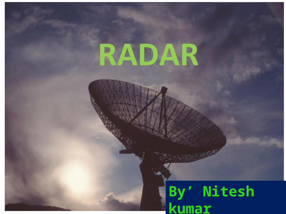
By’ Nitesh kumar
RADAR SYSTEMS Prepared by :
NITESH KUMAR E&Tc Dept.-6th SEM ID No.:110712009 IIEST,SHIBPUR

CONTENTS 1.INTRODUCTION 2.BASIC PRINCIPLE
3.CLASSIFICATIONS
4.RADAR TECHNOLOGY
5.RADAR COMPONENTS
6.APPLICATIONS
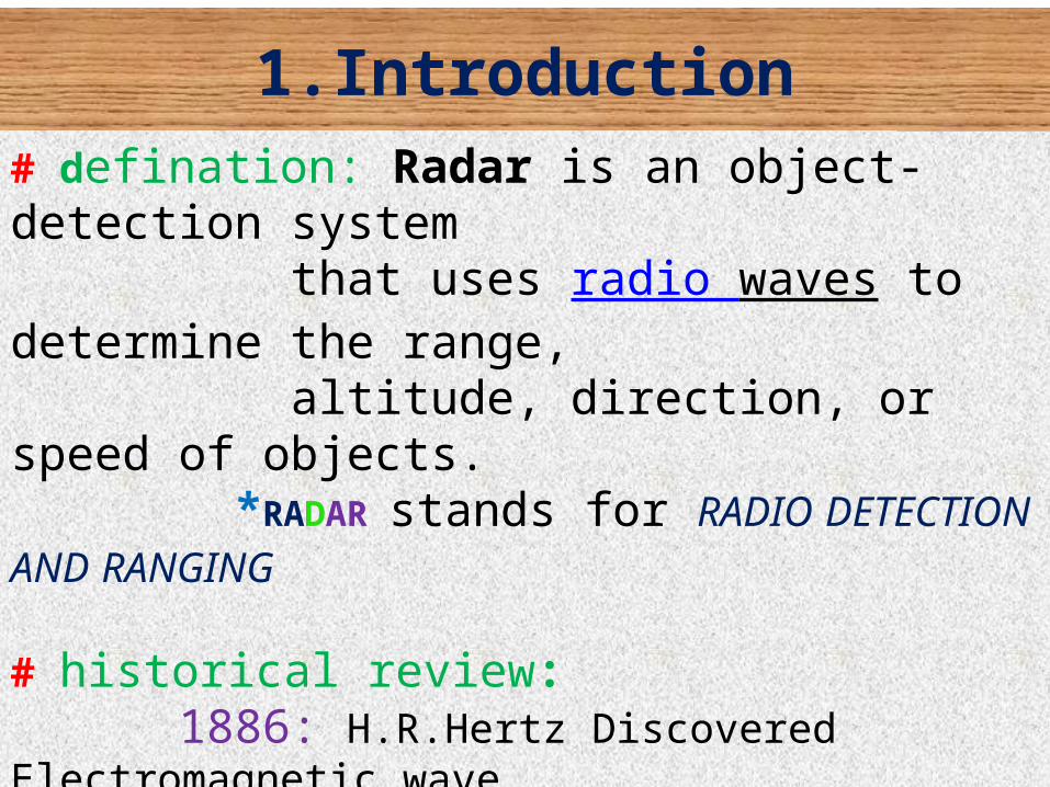
1.Introduction# defination: Radar is an object-detection system that uses radio waves to determine the range, altitude, direction, or speed of objects. *RADAR stands for RADIO DETECTION AND RANGING
# historical review: 1886: H.R.Hertz Discovered Electromagnetic wave. 1897: G.Marconi (known as pioneer of radio communication) firstly transmitted electromagnetic wave for long distance. 1930: L.A.Hyland,Locates an aircraft for first time.
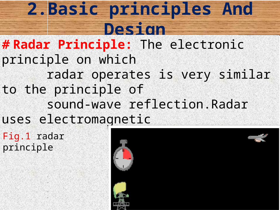
2.Basic principles And Design # Radar Principle: The electronic principle on which radar operates is very similar to the principle of sound-wave reflection.Radar uses electromagnetic energy pulses in much the same way. The radio- frequency (rf) energy is transmitted to and reflected from the reflecting object.Fig.1 radar principle

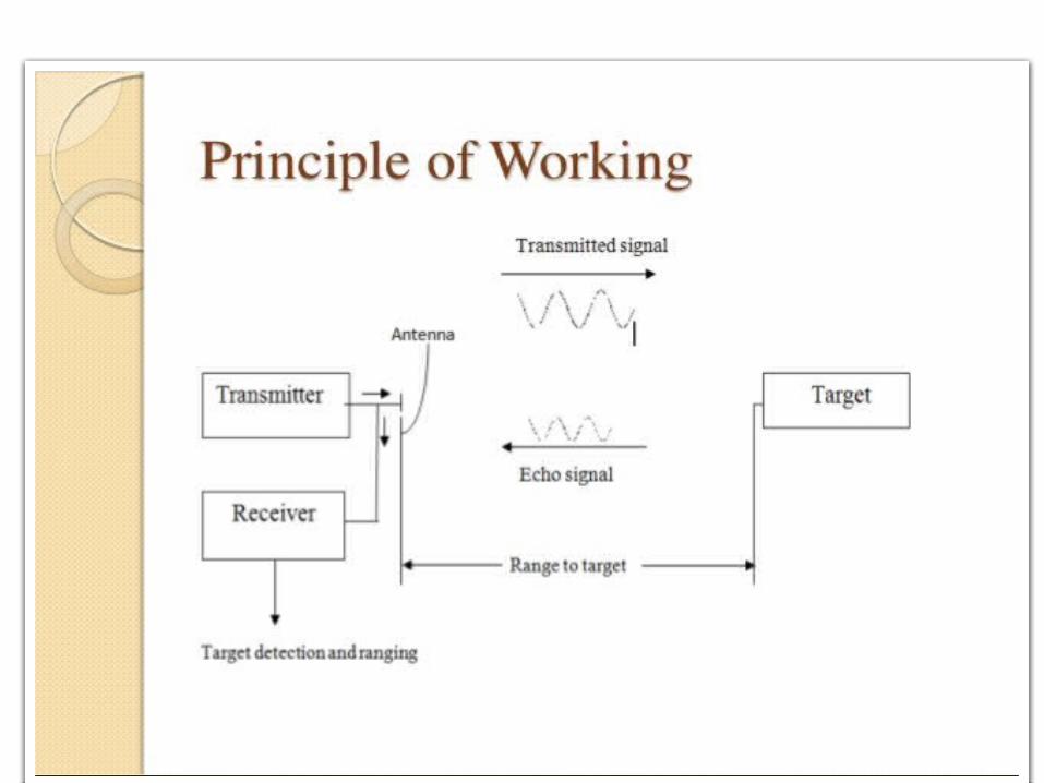
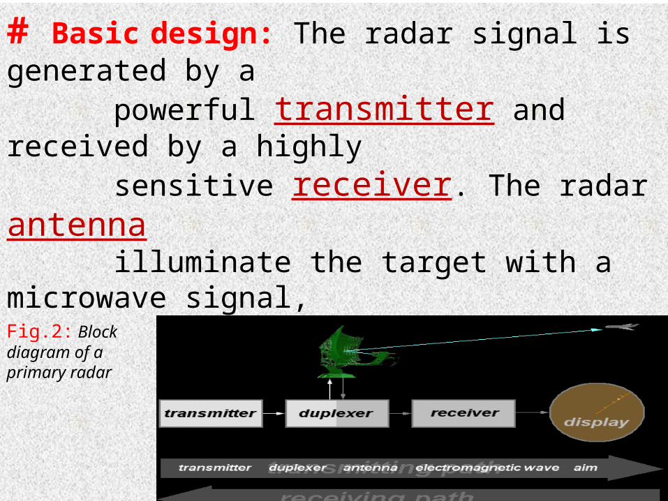
# Basic design: The radar signal is generated by a powerful transmitter and received by a highly sensitive receiver. The radar antenna illuminate the target with a microwave signal, which is then reflected and picked up by a receiving device and Radar signals can be displayed on the traditional plan position indicator (PPI) other more advanced radar display systemsFig.2: Block diagram of a primary radar
# Important terms: Some frequently used term are –1.Maximum Unambiguous Range:The maximum range at which a target can be located such that the leading edge of the recieved backscatter from that target is receivd before transmission begins for the next pulse. This range is called maximum unambiguous range
Where ; PRT is pulse repetition time Pw is pulse width
Rmax
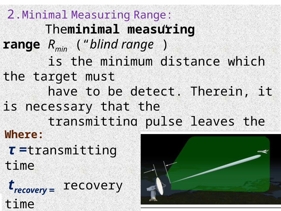
2.Minimal Measuring Range: Theminimal measuring range Rmin (“blind range”) is the minimum distance which the target must have to be detect. Therein, it is necessary that the transmitting pulse leaves the antenna completely and the radar unit must switch on the receiver. Rmin
Where: τ =transmitting time
trecovery = recovery time
Fig:The Radars “blind range”

# The Radar equation: (Argumentation/Derivation)
Radar range equation represents the physical dependences of the transmit power, one can assess the performance of the radar set with the radar equation (or the radar range equation). Non directional Power Density (su) : Directional Power Density (sg) : Sg = Su · G The reflected power Pr : [W/m2]
The received power PE : PE = Se · AW [W] =

PE = The Antenna Gain (G):
The radar range equation:
R= Where: PS = transmitted power [W σ = radar cross section [m2] R1 = range, distance antenna - aim [m] R2 = range aim - antenna [m] Aw =Effective apparture antenna [ =A · Ka

3.Classifications
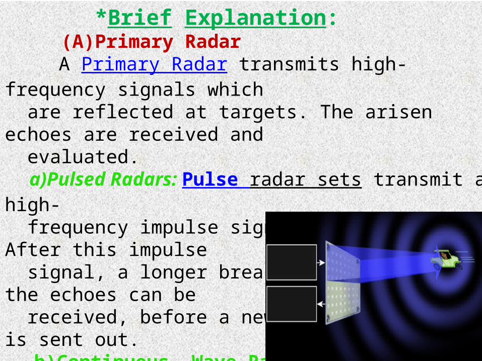
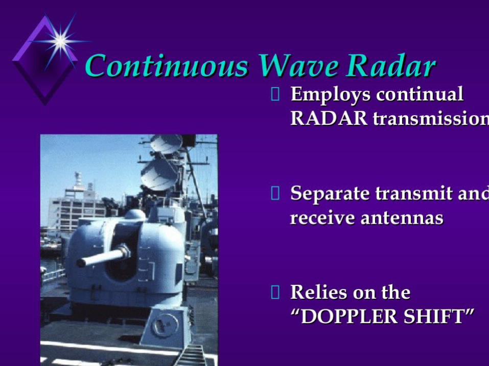
*Brief Explanation: (A)Primary Radar A Primary Radar transmits high-frequency signals which are reflected at targets. The arisen echoes are received and evaluated. a)Pulsed Radars: Pulse radar sets transmit a high- frequency impulse signal of high power. After this impulse signal, a longer break follows in which the echoes can be received, before a new transmitted signal is sent out. b)Continuous- Wave Radar: CW radar sets transmit a high-frequency signal continu- -ously. the transmitting antenna and the receiving antenna are separate. Fig:The continuous wave radar


(B) Secondary Radar: Defination: A secondary radar system is a cooperative Target identification system in which the interrogator Transmits an encoded signal to the target. the signal transmitted by the secondary radar is intercepted and received by the target .the target has a transponder on board that interperts the encoded signal and transmits an encoded reply back to the interrogator .the secondary radar systems receives and interprets the target encoded signal. * Two important part: 1)Ground interrogator 2)Air Craft Transponder *It provide IFF (Identification of friend And foe). Fig :Block diagram of a secondary radar

*Pictorial View

4.Radar technology:
# RADAR SIGNAL PROCESSING
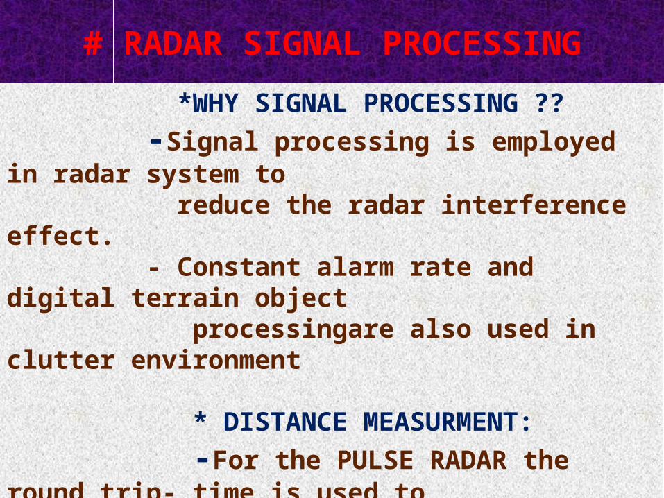
*WHY SIGNAL PROCESSING ?? -Signal processing is employed in radar system to reduce the radar interference effect. - Constant alarm rate and digital terrain object processingare also used in clutter environment
* DISTANCE MEASURMENT: -For the PULSE RADAR the round trip- time is used to detect the distance. -In CONTINIOUS WAVE RADAR is measured by the product of one-half of the trip time and the speed of signal.
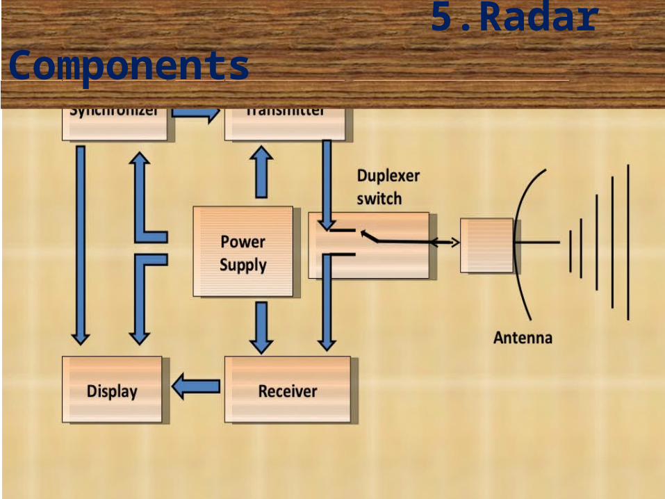
5.Radar Components

1.ANTENNA
. The Antenna is the transitional structure between free-space and a guided devices
. Type: a)Wireless Antenna b)Aperture Antenna c)Reflector antenna d)microstrip antenna
. Antenna Characteristics: 1)Antenna Gain: It is the ratio between the amount of energy propagated in these directions compared to the energy that would be propagated if the antenna were not directional .
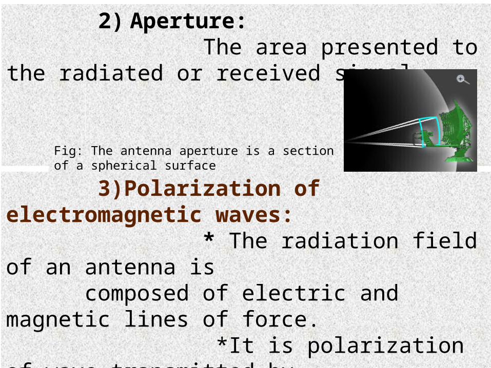
2) Aperture: The area presented to the radiated or received signal.
Fig: The antenna aperture is a section of a spherical surface
3)Polarization of electromagnetic waves: * The radiation field of an antenna is composed of electric and magnetic lines of force. *It is polarization of wave transmitted by antenna. 2) Beam Width: The angular range of the antenna pattern in which at least half of the maximum power is still emitted
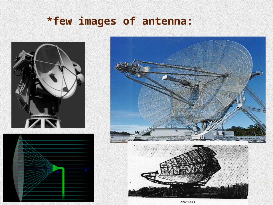
*few images of antenna:

2.RADAR TRANSMITTER
* A radar transmitter generates RF- energy, necessary for scanning the free space.
*It should have the following operating characteristics: a)The transmitter must have a suitable RF bandwidth b)The transmitter must be easily modulated to meet waveform design requirements.
*Type: 1.Keyed-oscillator type 2.Power-Amplifier-Transmitters (PAT)
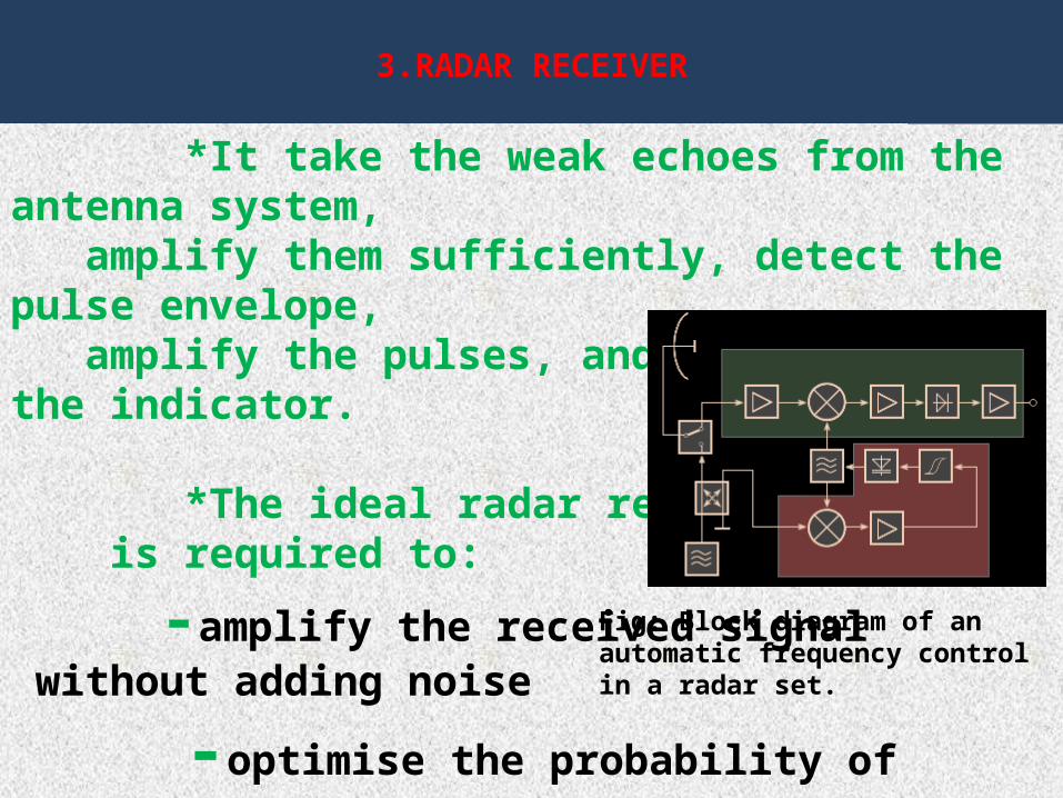
3.RADAR RECEIVER
*It take the weak echoes from the antenna system, amplify them sufficiently, detect the pulse envelope, amplify the pulses, and feed them to the indicator.
*The ideal radar receiver is required to:
-amplify the received signal without adding noise -optimise the probability of detection of the signal by its bandwidth characteristisc. -reject interfering signals
Fig: Block diagram of an automatic frequency control in a radar set.

• Few images of receiver

4.DUPLEXER * DUPLEXER is an electronics switching circuit that allow time share a single antenna between the transmitter and receiver signal.
* THE BALANCED DUPLEXER is based on the shortslot hybrid junction which consists of two sections of waveguides joined along one of their narrow walls with a slot cut in the common wall to provide coupling between the two.Figure 11.3 Balanced duplexer consisting dual TR tubes and two short-slot hybrid junctions. (a) Transmit condition and (b) receive condition
.
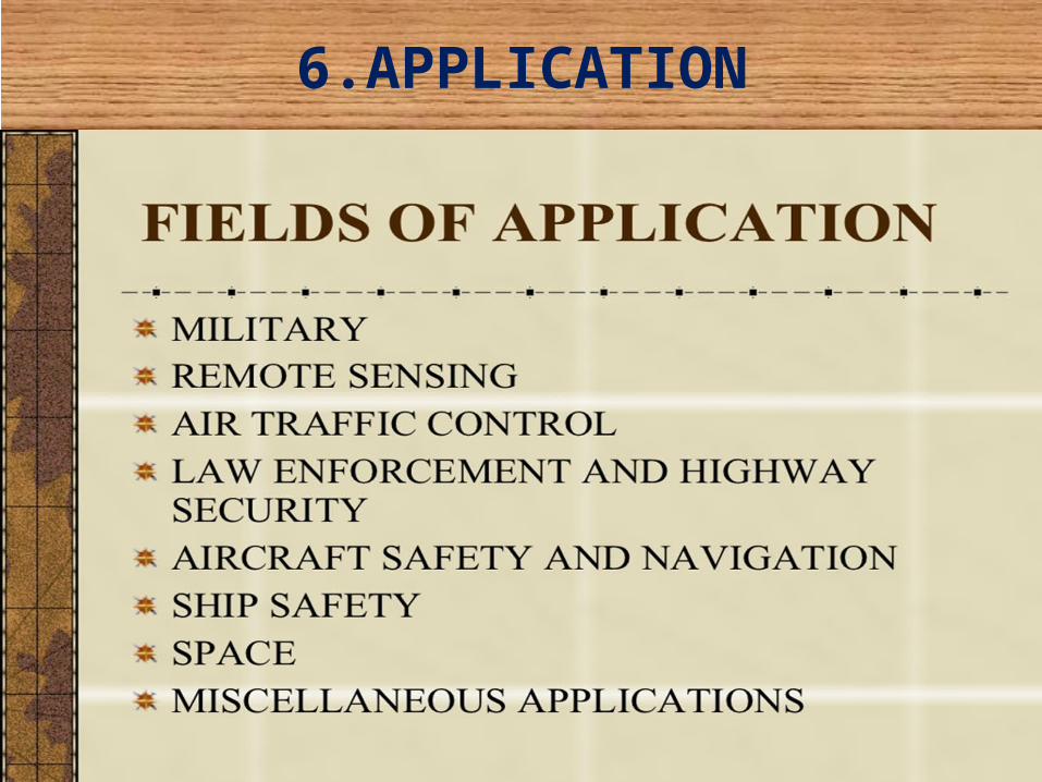
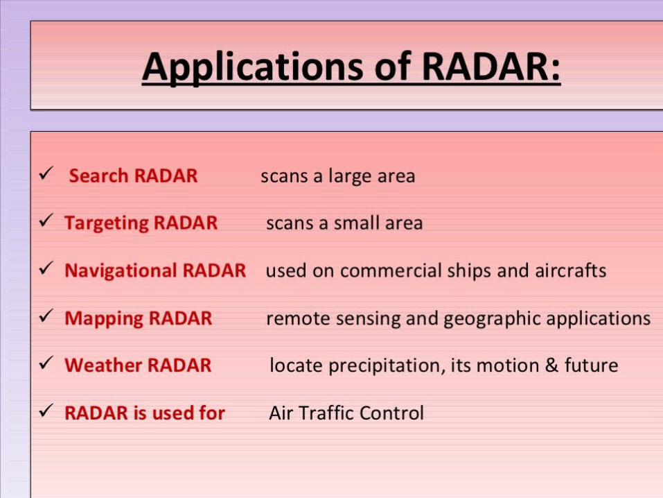
6.APPLICATION
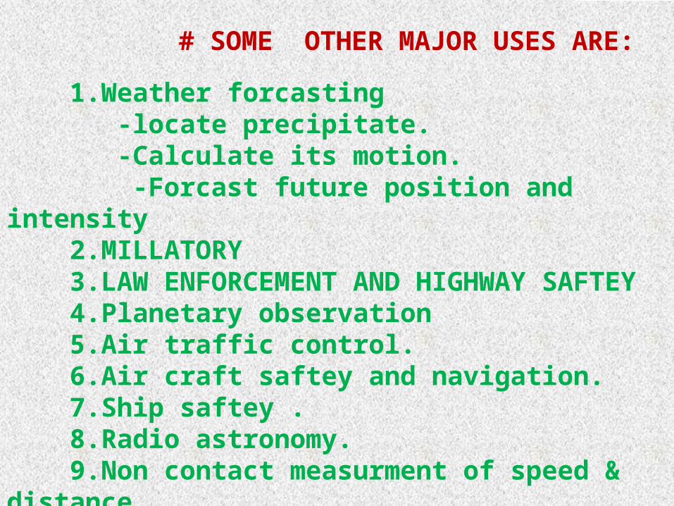
# SOME OTHER MAJOR USES ARE:
1.Weather forcasting -locate precipitate. -Calculate its motion. -Forcast future position and intensity 2.MILLATORY 3.LAW ENFORCEMENT AND HIGHWAY SAFTEY 4.Planetary observation 5.Air traffic control. 6.Air craft saftey and navigation. 7.Ship saftey . 8.Radio astronomy. 9.Non contact measurment of speed & distance. 10.Oil and gas exploration. 11.GPR Application;locate pipes ,utilities,burried object.