Radar News 19 -
21
Air Scientific Intelligence Technical Translation No. 8. “Radar News No. 19” Translation of “Funkmess-Nachrichten No. 19” Air Ministry 15.7.45 A.D.I. (Science) [most likely R.V. Jones, AOB] Secret Oberkommando der Luftwaffe 25th February 1945 Genralnachrichtenführer Nr. 40 164/45 g.Kdos. Ln.Insp. 6 Abt. IA “Radar News” No. 19. Contents A) The Present Radar Situation. B) Ground Radar Developments. C) Airborne Radar Developments “Radar News” Nr. 19 is to be distributed to fighter groups and signal officers. “Radar News” is distributed directly to groups by the Director General of Signals. 1) “Radar News“ No. 19 should keep the Signals Officers, the radar specialists and the aircraft reporting officers informed of the radar situation as at present, and tell them of new apparatus
Transcript of Radar News 19 -
Air Scientific Intelligence Technical Translation
No. 8.
“Radar News No. 19”
Translation of “Funkmess-Nachrichten No. 19”
Air Ministry 15.7.45 A.D.I. (Science) [most likely R.V. Jones, AOB]
Secret Oberkommando der Luftwaffe 25th February 1945 Genralnachrichtenführer Nr. 40 164/45 g.Kdos. Ln.Insp. 6 Abt. IA
“Radar News”
No. 19.
Contents A) The Present Radar Situation. B) Ground Radar Developments. C) Airborne Radar Developments
“Radar News” Nr. 19 is to be distributed to fighter groups and signal officers. “Radar News” is distributed directly to groups by the Director General of Signals.
1) “Radar News“ No. 19 should keep the Signals Officers, the radar specialists and the aircraft reporting officers informed of the radar situation as at present, and tell them of new apparatus
2) Extracts from this publication can be made by Divisions and distributed to subordinate units whose duties call for knowledge of these subjects
Signed: Martini. F. d. R. [It is clear that this text is meant for German
wartime personnel, AOB]
A. RADAR: THE PRESENT SITUATION I. THE ENEMY’S JAMMING OPERATIONS
1. Ground Radar.
(a) “Window” Jamming [German text would have used: Düppel, AOB] There is no further information available on this subject. (b) Airborne Jamming The most noteworthy are the isolated cases of airborne jamming to “Köthen Grey” (6.0 m. wavelength). Several instances of airborne jamming to “Köthen Brown” (3.65 m. wavelength), “Köthen Red” (3.4 m. wavelength) and the apparatus in the D-Band (1.5 – 1.85 m. wavelength) have also been observed. There is one report of airborne jamming to “Köthen White” (4.05 m. wavelength). The airborne jamming of Würzburg apparatus is carried out now, as before, by airborne jammers in four-engined bombers (except for the “spoofing’ operations by 100 Group on the Western Front, and a recce by long distance night-fighters). (c) Ground Jamming On the Western Front ground jamming of C-band (“C-Insel” (3.0 – 3.3 m. wavelength) is the most significant; jamming [maybe meant to jam Li-SN2 night-fighter airborne radars, AOB] of apparatus on “Köther Yellow-Red” (1.80 m. wavelength), “Green” (3.15 m. wavelength), “Brown”, “White”, “Grey”, A- (2.48 – 3.32 m. wavelength), B-band (2.08 – 2.24 m. wavelength) and on D-Apparatuses has only been reported in isolated cases. Exhaustive observations of this jamming in co-operation with the Radar Intercept Service lead to the conclusion that we are dealing with deliberate enemy jamming by noise jammers on the frequencies of the jammed apparatus. The jammed sector amounts to an average of about 30° to 40°; the effect of this jamming on the air situation is thus not so serious as in airborne jamming, because in that the jamming sector at a distance of 150 km. amounts to about 30°, at 100 km. to 60° to 90° and at distance of 60 km. to 360°. Radar sites on the coast report Wassermann jamming [this could then only yet have been Dutch sites, considering the distance between S-E England and Denmark territory, AOB], the jamming maxima of which point principally towards
south-east England. Jamming received from other sectors may be attributed to side-lobes of the receiver antenna or possibly to ship-borne jammers. These types of jamming are, however, much rarer than airborne jamming. All cases of ground jamming of Würzburg sets give bearings towards the Reich, and provide no D.F cuts. They may be attributable to jamming by DM-lines [likely meant Decimetric telephone links, as these operated also in some of the Würzburg spectra, AOB] or may emanate from enemy aircraft, fitted with airborne jammers, flying some distance away radically to the Würzburg positions. 2. Airborne Radar
(a) Airborne Jamming
As a result of recent research, it seems very probable that enemy airborne jammers are directed against spot-frequencies (“Streuwellen”) IV, V and VI of the SN21. Plotting of aerial targets is made difficult at present. An exact investigation into the cause of jamming in co-operation with the Radar Intercept Service is still in process. As a source of airborne interference, the British airborne jammers used against Freya frequencies (C, “Green”, “Red”, “Brown” and “White”) must be taken into consideration. According to the most recent intelligence, long distance night-fighters are coming into use for jamming purposes. (b) Ground Jamming Considerable interference from our own jammers of the enemy Gee systems (“Hyperbelsysteme”) [type Heinrich, AOB] are apt to come up on the SN2 spot frequencies V and VI [maybe against G-H, AOB]. This occurrence can be countered only by switching off “Heinrich” transmitters during night-fighter operations. Spot frequency IV is not affected by these jammers. Enemy ground jammers against Freya wavelengths interfere with SN2 operations, particularly in the western area of the Reich. II. OUR OWN RADAR OPEARTIONS
The jamming tactics and techniques of the enemy, (which are characterised by their flexibility and the numerical superiority of material used) together with the industrial capacity at our disposal and the physical and technical possibilities known to us, determine our own high frequency radar situation. The following points summarise the principal aspects of our own radar situation:
1) The principle of the “stop-gap system” used in the conduct of the war as a whole, applies particularly to the high frequency “war”. Standardisation such as is permissible for a certain time for other types of equipment, cannot, therefore, be carried out as a matter of course in high frequency techniques, especially if one is in the defensive. 1 T.N. Spot frequency IV = 3.30 metres; V = 3.7 metres; VI = 4.1 metres
2) This conclusion is based on the fact that, at the moment, no means are visualised which would bring complete freedom from jamming to the world of radar. An effort must therefore be made, by means of variety of improvisations and stop gaps, to overcome the present overmastering jamming techniques of the enemy. [Martini might have omitted mentioning the existence of the centimetric Berlin-A radar, for security reasons, maybe also because it was only available in quite limited numbers. Estimated about 150 working systems at the break of the hostilities in May 1945, AOB]. 3) Because all equipment and stop-gap measures are only temporary, and can remain effective only until they are detected by the enemy, all the possibilities which are visualised for anti-jamming reach the operators in the form of short term equipment. If a long period of experiment and laboratory research has taken place before they come into operation, the possibility must be faced that the measure may have already been superseded by the time they are introduced to the operators. 4) These modifications and new issues, and the simultaneous operation of large number of different types of sets, imposes a heavy burden on the operators, especially with the manpower situation as it is at present. But no solution to the difficulties resulting from this state of affairs is to be found in a standardisation of radar technique. This would be the equivalent of final capitulation to the enemy’s jamming operators. 5) Similarly it would be mistake to give up all sets on frequencies particularly jammed by the enemy at present. A certain number of these sets must be kept in operation for “spoofing”; the more frequencies that are in use, the more the enemy has to divide his jamming effort. In this way the enemy can be prevented from concentrating his whole jamming organisation at a few wavelengths, which he could jam continuously. 6) Alleviation of the difficulties is to be sought in an increased desire on the part of the men for better training and intensive education of all ranks and classes of operators engaged on aircraft reporting and radar. 7) If the operators know the technical possibilities and limits of individual types of apparatus, it is usually possible to form a picture of the air situation with the majority of the various apparatus types, during most cases of strong jamming, by appreciate choice of A-J procedures corresponding to the jamming situation obtaining. [meant is coherence like Würzlaus; or video differentiation like Taunus or Doppler range gating like Nürnberg, AOB] (See pamphlet soon to be published “Appreciation of the Air Situation During Enemy Jamming”.) B: DEVELOPMENTS IN GROUND RADAR TECHNIQUE. I. JAGDSCHLOSS 1. Jamming Photography. In order to obtain particulars about Jagdschloss jamming, small cameras (Leica or Robot) were issued to individual sites by Gen. Nafü 6 Abt. [General Nachrichtenführer, AOB]. The photographs are urgently needed for further development of anti-jamming procedures. The photographs received to date are scanty. In order to improve this position, attention is drawn to the following points:-

(a) The best conditions for photography will be obtained by means of test photographs (without jamming):
Try out various settings of the brilliancy control of the P.P.I. tube. The brightness is correct when the grid is faintly discernible on the photograph. Choose films with various sensitivities (17/10 Din, 23/10 Din) [respectively 50 ASA and 150 ASA?, AOB].
(b) When taking a photograph, consult the “Instructions for taking small photographs of the P.P.I. tube” ( published by the Experimental Station at Werneuchen).
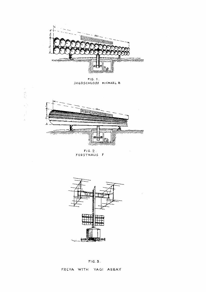
In part IV, para. D, the following should be added to sentence 2: Adjust the short exposure knob (seen from above it is on the left to the release knob) to Z [Z probably means Zeit, AOB]; exposure time regularly by long exposure knob (seen from above it is on the right, next to the objective lens) remains at 1/30, as given in sentence 2. (c) For better recognition and examination of the picture sequence, a clock face (luminous) is to be included in the photograph. (The illumination power of the figures is increased by previously shinning an electric torch beam on them.) [due to the application of real “radium” commonly used in the world, AOB]. The clock face must always remain on the same spot, so that the direction may be determined from it. (d) Individual series of photographs are to be separated by a blank. At the beginning of each film a photograph of permanent echoes should be taken, and then a blank photograph, so that the image sequence may be clearly established. (e) A photograph list is to be compiled for each film, containing data, time and type of jamming recorded or peculiarities. (f) Exposed films must be brought to Gen. Nafü 6 Abt. (IC) by courier. Here the films are developed as quickly as possible, and suitable enlargements prepared. If possible, operators who have accurate information about the photographs should be sent as couriers, who can, if necessary, answer any questions. 2. Artificial Earth of Wire Netting and Elimination of the First Gap in the Coverage. The experimental station at Werneuchen succeeded, by setting up an artificial earth of wire netting (see Fig 1) at a radius of approximately 50 – 60 m. round the Jagdschloss, in eliminating the lowest gap in the coverage and in considerably increasing the range against flying aircraft. The Todt organisation [in fact a quasi civilian organisation providing all sorts of construction work, AOB] put up the wire netting earths for the most important Jagdschloss sites. About 1 ton of wire netting is required per station. At the moment nothing more can be said about the time when supply will be completed. A pre-requisite, for the efficacious construction of wire netting earth, is an accurate knowledge of the gaps in the coverage in three directions separated by 120°.
As no trial flights with test aircraft for determining the lobe pattern are possible at the moment [due to the lack of aircraft fuel, AOB], sites must ascertain the gaps in the coverage systematically from normal flights. The altitude of the aircraft are to be determined in co-operation with the Giant Würzburg. The observations should extend over a long period of time. 3. Accuracy of the P.P.I. Experiments were carried out by the Air Signals Experimental Regiment at Köthen in order to ascertain the accuracy of the P.P.I.. With a normal P.P.I. the values at distances up to 100 km., lie in the region of approximately 5 km. error. Efforts are made to improve accuracy by superimposing range circles on the P.P.I. screen electronically. 4. Getting rid of Mains Interference on the P.P.I. The P.P.I., as installed up to present, suffered from hum interference from the 50 cycle [50 Hz] frequency of the mains, so that the blips did not come up as exact arcs of a circle but as wavy lines. Methods were worked out and co-ordinated by the firm [Siemens & Halske one of the leading German firms, AOB] of Siemens in order to diminish this disadvantageous effect on the Siemens P.P.I. The work of getting rid of mains interference on the Siemens P.P.I. tube then in operation was carried out by the 25th Technical Company. The firm Fernseh AG are also working at present at getting rid of hum interference on their P.P.I.’s. After the resultant co-ordination of these measures, the Fernseh P.P.I.’s at present in use by our radar operators will also be improved. The results achieved up to the present already show that getting rid of the mains interference on the P.P.I. does not, of itself, suffice. Besides this, yet another video frequency cable must be displaced in the installation. [thus one course might have been that the 50 Hz hum was picked up via the video signal cable, AOB] The experimental station at Werneuchen are working on this project at the moment. Progress will be currently reported in “Radar News” [this latter issue might never have come out owing to the ending of the war, AOB]. Freeing the P.P.I. from mains interference is of particularly great significance with regard to the work being done at present on “anti-Window” [anti-Düppel, AOB] measures for Jagdschloss installations, so that from the site commander’s point of view great stress is laid on this problem, and every suggestion must be reported as quickly as possible. The Division will forward the reports to Gen. Nafü 6 Abt. 5. Installation of Nullodes (Spark Gaps) [here the translation is clearly incorrect. Nullodes are like soft Sutton tubes or in modern terms: T/R cells. Their content of water vapour (≈ 1 mm Hg) contained in a glass envelope, is being ignited by means the EM field surrounding it, AOB] Together with the action taken against hum interference, the SD6 diodes were taken out of the common T and R units and replaced by nullodes.2 The nullodes should ensure a considerable greater efficiency, so that it is to be expected that in this way the most 2 This may have been the reason why so many SD6 where around in the 1970s and 1980s.
frequency source of faults [meant faults, AOB] up till now (failure of the SD6 diodes) has been eliminated. [how this was accomplished I don’t know. Did they deliver a SD6 like envelope having two electrodes covered in water vapour?, AOB] The units are to submit reports of experiences regarding the working effiency of the nullodes to OKL, Gen. Nafü 6. Abt. II. Closing date, 30.3.1945. [OKL = Oberkommando der Luftwaffe, AOB] 6. Installation of the “Display Selector” (Bildwähler). “Display selectors” will shortly be installed in existing Jagdschloss stations, by means of which display of ranging, ranging + recognition3, and recognition can be selected. The operators selected for carrying out this work have already completed a course with Siemens. [Then they only could monitor IFF signals on the P.P.I. the video-line should have been switched-off (disabled), AOB] An “Erstling”4 monitoring stations necessay at Class 1 stations for the efficient tuning of the I.F.F. II. ANTI-‘WINDOW’ MEASURES FOR JAGDSCHLOSS, WHICH ARE
SHORTLY COMING INTO OPERATION 1. Electrical Lens. A prototype of an electrical Lens has been developed for the P.P.I. [also known as “Sternschreiber”, AOB] In this, the centre point is displaced to the edge of the (P.P.I.) tube and a greater time base deflection voltage is used to form the image. The surface enlarged in this way can be tuned to form the image. The surface enlarged in this way in this way can be turned to any chosen sector. The [screen, AOB] enlarged in this way can be turned to any chosen sector. The enlargement factor has a ratio of about 2:1 to 3:1 as against the normal Jagdschloss image. [In this case, they could not monitor what is happening in 360° though now in sections of say 120 to 180°, AOB] 2. “Münchhausen” Procedure. Coloured films for differentiating aircraft echoes. Developing time, 1 to 2 minutes. Permanent echoes appear as dark spots, aircraft as dark spots with red and blue borders in their direction of flight. The procedure has proved satisfactory during “Window” [Düppel, AOB] interference at the experimental station at Werneuchen, so that an apparatus for trials at operational Jagdschloss installations is now being arranged. III. RECENT “PANORAMA” (P.P.I. RADAR) DEVELOPMENTS. The results obtained to now during anti-“Window’ trials and during heavy raids show that in most cases only installations with a strong horizontal beam concentration can provide a clear picture of the aerial situation. [I guess the Germans used the word: Luftlage, AOB] Because of this, all the new developments connected with “Panorama” take fact into account. 3 Recognition is IFF or “Freund/Feind-Kennung”. 4 Erstling is the codename for their aircraft IFF transponder type FuG25a.
(a) In the apparatus with narrow beams, the ratio of useful energy during “Window” [Düppel, AOB] jamming is considerably more advantageous than in apparatus with wide beams. [they clearly point at the advantage of cm systems versus their decimetric or metric systems, AOB] It should be noted that in these apparatus extensive “Window” jamming comes up as a bright haze, though which the aircraft may be picked out as brilliantly illuminated points. (b) These installations are also practically immune to jamming transmitters, because as a result of their narrow beaming, a jammer takes effect only within a small sector of about 1°. [also the wide frequency spectra of cm radar is hampering the effort of effectively jamming, AOB] (c) Furthermore, increased range should be achieved through close horizontal beaming. (d) Besides this, gaps in the coverage should be eliminated with the new installations and it should be possible to pick up high-flying aircraft flying at altitude up to 14 km. [their Berlin-A (FuG224 A) suffered however from this phenomenon, it proved to be necessary to determine exactly for every aircraft type the mounting of the radar antenna. See my CAVMAG2010 contribution CAVMAG-2010-Wartime%20Struggle.pdf ,AOB] It is planned, after the solution of the I.F.F. question, to set up these installation together with “Jagdhütte” for the purpose of fighter control over large areas. A row of installations is therefore visualised in the neighbourhood of the Divisional battle headquarters. Use should be made of the great range of individual installations by employing them as early warning sets. 1. Jagdschloss Michael B. P.P.I. search set on the Würzburg band with a horizontal beam width of 1°. The beam concentration is achieved by 2 x 18 Würzburg D mirrors [of the small Würzburg, AOB] on a rotating aerial 56 m. in lengths. [please remember that this issue was dated 25 February 1945!, AOB][this only works when these beams are mutually phase controlled, AOB] The coverage gaps are eliminated by switching over to a second frequency in the Vollwismar Band III. Estimated range against single aircraft, 220 km. 2. Forsthaus F. P.P.I. search installations on 25 cms (Euklid Welle) 25 cm. (25 cm. naval transmitter.) The installation has a 56 m long rotating aerial in the form of a horizontal cylindrical paraboloid. In the line of focus, and arranged above and below it, there are three wave guides. By selecting one of these three lines the transmitting and receiving lobes are shifted perpendicularly, and in this way the gaps in coverage are avoided. 3. Forsthaus KF. P.P.I. search installation on 25cm. and with the same circuits as Forsthaus F, but with a rotating aerial 24 m. long.
Planned for quick release as soon as possible in the West to bring P.P.I. [the most likely used the word: Rundsuchanlage, AOB] search installation on new frequencies into operations. It is planned to install single Forsthaus KF installation in railway installations and mobile Z-installations.5 Estimated range: 120 km. 4. Jagdschloss Z, Forsthaus Z. Centimetre development on “Berlin” frequency with aerial 24 m. long. [Meant Berlin-A or FuG224, operating in the S-band, AOB] Two developments by Siemens (Jagdschloss Z) and Telefunken (Forsthaus Z) which differ fundamentally in the layout of their aerials. Estimated range:120 km. The first installations are estimated to become operational in April or May. [1945!, AOB] A mobile version of the Centimetric Jagdschloss installation will also be needed. 5. Estimated Introduction of the New “Panorama” Installations. Construction of the Forsthaus F and Jagdschloss Michael B installations is at present in progress. It will be carried out with the greatest urgency. It was planned that all the installations would be set up by the beginning of July 1945. To what extent this programme has been upset by the ground of situation cannot be judged at the moment. [here they take the present war situation into account, notice, Germany was falling apart and the Ruhr was becoming to be lost soon, Silesia was already occupied by the Russians …, AOB] The construction of centimetre sets is intended to be carried out in such a way that new supplementary installations are set up at individual centres of importance for air defence. [remember, the GAF lacked 90% of its aircraft fuels!, AOB] In the other parts of the Reich existing Jagdschloss should be modified when possible. [usually, the RF modules, including the transmission section, was replaced by Berlin-A technology, keeping the rest unchanged, AOB] 6. “Jagdwagen”, Small “Panorama” Installation. Lorenz have designed a small P.P.I. installation with an aerial 8 m. long, which works on the “Hohentwiel” band. [about 490 MHz, AOB] Horizontal beam width of about 6° (as in normal Jagdschloss sets). Range about 40 – 60 km. for medium altitudes. The installations are primarily designed for use on airfields. It is also planned, however, to set up a single mobile types. The first “Jagdwagen” apparatus is at present undergoing trials at the Werneuchen experimental station. IV. Ground “Hohentwiel”. A small radar apparatus on the “Hohentwiel principle is being developed by the Signals Experimental Regiment [at Köthen, AOB] it will be used as ground radar by the motorised Companies. The apparatus is carried in a type 17 van, and can be set up in about 15 minutes. During trials it showed a range of about 30 – 35 km. against single aircraft, and of about 60 – 70 km. against formations. 5 Z = demountable [= Zerlegbar, AOB]
V. Freya. 1) Allotment of frequencies. In order to gain new operating reserves, it has been planned to change the frequency of jammed Freyas to new frequencies. These are: (aa) “Köthen Blue” (Yagi). The blue sets need a site elevated about 30 m. above the immediate surroundings, on account of their long wavelength. (bb) “Köthen Violet (Yagi). There are no particular requirements for siting, but positions in valleys should be avoided. The use of this band is planned in connection with the “Snap Plotting Unit” (Kurzzeitmessung) (see under b.). (cc) “Köthen Red-Black (Yagi) and “Köthen Green-Black”(Yagi). These two bands on the English “Gee” frequencies [whether the German text used Gee is unlikely, they might have used instead: Hyperbelnavigationsfrequenz, AOB]. Noise jamming is not anticipated, as it would interfere with the enemy’s own navigational system. Use of “Green-Black” and “Red-Black” frequencies is possible, above at all, at night, when the “ Heinrich” jammers are switched off. Sites chosen should be, if possible, some distance from concentrations of jamming transmitters. Undisturbed operation is possible at the most favourably selected sites even when the “Heinrich” jammers are switched on. (b) As a result of the enemy’s increased jamming operations, a portion of the Freya band has now only a limited value for radio location (see I 1). Freya sets on the bands which report continuous jamming are to be converted on first priority to the new frequencies. (c) A number of these frequencies must, however, be left in operation for the following reasons:-
(aa) The jammed sets enable an immediate assessment of the jamming to be made, and a fix to be taken on the jamming aircraft, both of which are of value in completing the picture of the aerial situation. [the Germans most likely used: Luftlage, AOB]
(bb) The enemy must be confronted with as wide a frequency band as possible so that he is forced to work his jammers on all frequencies, thus increasing the difficulty of concentrating the jammers about one wavelength.
(d) For the operational purposes described under 1 and 2, only a few sets are necessary for the frequencies used at present. Orders as to how many sets are to be left in use and on which frequencies, are being sent to the operating companies. Sets used in this “Radio Camouflage and Jamming Evaluation Organisation” [Likely German word: Funktäuschungs- und Störauswertungskommando?, AOB] are to remain at strategic points in the area within optical range of the Western enemy. Thin frequency cover is also to
be left in other areas, because of the enemy’s radar intercept flights. These sets must particularly be switched on when single aircraft approach, as it may be assumed that these aircraft particularly are flying on radio reconnaissance. Frequencies still free from jamming should, in principle, only be resorted to when there are large enemy ops. (In so far as there are no particular operational orders for individual frequencies.) In every case care should be taken that all the ground radar sets do not open up when single enemy aircraft (radio recce?) approach. Operation of a few radar sets is fully sufficient for tracking these single aircraft. 2) “Snap Plotting” Procedure (Kurzzeitmessung). A so-called “Snap Plotting” unit is inserted in the pulse frequency circuits of the Freya modulator (TS-Teil). The “Snap Plotting” apparatus consists of several relays and a time delay switch which release the Freya transmitter by actuating a key for a period of 10 pulses. [Freya PRF = 500 Hz hence 1/f = 2 ms. → the gate time = 10 x 2 ms is 20 ms, AOB] The time delay switch allows the time intervals between the pulse groups [bursts, AOB], (10), to be adjusted between 2 and 22 seconds. The observer can thus operate the transmitter by pressing the key after preset time has elapsed. The reflected pulses come up to the time base of the coarse D/F tube. The coarse D/F tube is fitted with an afterglow screen, which persists about 3 seconds. The interception of frequencies working with “Snap Plotting” [Kurzzeitmessung, AOB] is made extraordinarily difficult to the enemy, as the 10 pulses produce, at the most, a mere click in the listening receiver. “Slit”(AN-Peilung) is not possible in conjunction with “Snap Plotting”. “Snap Plotting” should be coming into use for the new frequencies with the utmost priority. 3) 4-Line Presentation Unit. For Freyas used in Flamme plotting [exploiting Allied IFF transmission for range measuring, AOB], Freya Fahrstühle [meant for measuring height, which Freya is otherwise unable to provide AOB], long range sets and “EGON” apparatus a range presentation unit of 0 – 300 km. is of great advantage. By modifying the NB 111 presentation unit display of a range of 0 – 300 km. is possible. [double the normal maximum of 150 km, AOB] This modification makes provision for two time base lines on each NB 111 tube. Upper Tube: Time base left to right (lower line) 0 – 80 km. “ “ right to left (upper line)150 – 230 km. Lower Tube: “ “ left to right (lower line)70 – 150 km. “ “ right to left (upper lime)220 – 300 km. Modification of the NB 110 presentation unit is not possible. In modifying the NB 111 an auxiliary scale must be put onto the cathode ray tubes. A description of how this modification may be carried out is expected shortly. 4) Mobile Yagi. The demand for mobile limbers with Yagi aerials has now been met. Delivery of the first converted sets may be expected shortly.
5) Substitute Valve Sockets for Freya Receivers. [please consider on our website exhibits new and exhibits details. The Freya receivers front-end was normally equipped with two acorn valves, these were however, mainly supplied by Philips Eindhoven. This factory was already liberated in September 1944 and apparently German stocks dried up. They redesigned the acorn base such that the regular RV12P2000 could be used instead. Maybe having a bit less HF amplification, AOB] For a great number of Freya frequencies, RV12P2000 valve using suitable substitute sockets have been fitted in the receiver and tried out, in order to overcome the scarcity of acorn valves PH 4672. The trials have given positive results. The manufacture of sockets has been ordered, and their delivery can be expected shortly. [PH = Philips, AOB] 6) Anti-“Window” Measures. (a) Freya Laus. The equipping of Freya sets with “Laus” [coherent signal processing, AOB] has been completed except for Freya Limbers Flum 42. The delivery of “Freya Laus” I M for mobile limbers can be expected within a few days. The circuit arrangements of the Freya components is somewhat different in the I M compared to the other equipments. The instructions for fitting the I M are given in a relevant supplement. (b) Laus Tester (Prüf. Laus). The first “Laus” testing apparatus have been distributed to the sites. The experiences of the operators are not yet known. (c) “Lichtblitz”. The “Lichtblitz” is an attachment for Freya Laus, and can work only in conjunction with it. The purpose of the apparatus is to compensate for the Laus effect of “Window” echoes, which occur when the wind speed is above 40 km/hour. [owing to wind, the Window or Düppel will get a virtual velocity and by itself and so giving it a Doppler modulation. This was countered in some Würzburg systems by means of “Windlaus”. Please notice my book: Deckname Würzburg on this website, AOB] Ten “Lichtblitze” were installed on various frequencies and tried out by operators in a large-scale trial. The trials and results have not, at present, yielded much satisfaction, as the operation of “Lichtblitze” is extraordinary difficult; the constancy of the preset frequencies cannot be guaranteed so that target following after the first interception is made extraordinary hard. No decision has yet been reached as to whether the “Lichtblitze” should be issued in large numbers. 7) Egon. (a) Egon I (Mobile). The Air Signals Experimental Regiment at Köthen were commissioned to design a mobile “Egon” set, by converting the mobile limber, Flum 42, to Egon frequency (Urwelle) [this might have been the general Erstling or FuG25a frequency (IFF), AOB].
The reception of the return frequency via the Duplex array has not resulted in ranges like these obtained with the “Egon” LZ stand. In the future, the Duplex array will be replaced by the ordinary “Gems”[should be Gemse, AOB] array, and apparatus already delivered will be re-equipped with these “Gems” arrays.[LZ = Luft-Zerlegbar, which means that it was designed for air transportation, AOB] Trials resulted in producing ranges similar those of the LZ stand. At present efforts are being made to design “Messkette”6 attachments covering 200 – 400 km. for the mobile Egon sets, and to incorporate them into the mobile “Egon” limbers. [Egon is in German wartime text written: EGON, AOB]. Until the “Messkette” attachments are introduced, the phase reverse switch is to be installed and used. [what actually is meant I don’t know, AOB] (b) Egon B. Jamming of the Egon return frequency must be expected in the future. In order to have an alternative for this eventuality, a “Green” Egon frequency has been created (“Green-Erstling”), also the broadband Egon apparatus, “Egonn-B”. [Erstling was the transponder apparatus inside the aircraft. I guess, that its operational frequency could be selected as to operate on more than one frequency band, AOB] “Egon-B” is a normal LZ stand of the Vollwismar I type. The normal radar units are used for the I.F.F. and the “Kuh” and “Gemse” are are emitted. [Kuh = is the ground transmitter sending pulses towards the aircraft transponder; Gemse is receiving the responding signals, AOB] The Egon frequency (“Red Erstling”), as also the “Green” frequency, (“Green Erstling”), can be adjusted by the frequency controls of the transmitter and receiver. The “Egon-B” set is fitted with a keyed transmitter, display tube and “Messkette” attachment. No decision has yet been reached as to whether the “Green Frequency” should be introduced for the control fighters. 8) Giant Würzburg G. (a) Frequency planning. The first attempts at converting the G attachment on the B-Band (2.08 - 2.24 metres) to the “Yellow-Red” (1.08 metres) frequencies were failures. After overcoming the difficulties and eliminating the faults which still accompanied the conversion, the “Comversion Company” of the Air Signals Experimental Regiment at Köthen were again put onto the job of converting the most heavily jammed G-attachments onto “Yellow-Red”. At present the factories are delivering G-attachments on “Yellow-Brown” and “Yellow-Red”. The development of the Vollwismar G-attachment (G I A) with “split” I.F.F. has not yet been concluded. Its introduction cannot be expected in the near future. (b) Anti-“Window”. Freya-Laus I L for the G-attachments have been distributed, and are being installed at present. [‘G’ may stand for Gema, the designing company of Freya, AOB] 6 “Messkette” = electrical phase shifter unit for range measurement [tuneable delay-line, AOB]
The Telefunken Engineer Zeetzer? is visiting the 25th Company in order to help and instruct them, as the installation of the Freya-Laus in the G-attachment is known to be particularly difficult. [Please consider: the antenna apperture of the Giant Würzburg is < 1° so that picking up targets is more a question of good luck than a matter of direct pointing at; additionally a small array on top of the 7.5 metres dish is using a Freya radar set. This set is having a far wider signal capture (aperture), so that the coarse parameters of a target is obtained, fine ranging and D/Fing was taken over by the actual Giant Würzburg, AOB] (c) Replacement by Nullodes. A Nullode has been provided to the common T and R unit, in order to avoid the continual faults of the G-attachment caused by the failure of the SD 6 Diodes. Re-equipment of the G-attachments with nullodes is being carried out in connection with Jagdschloss and Wassermann sets. [Nullodes were commonly used in coaxial systems, where their activation is de-tuning coaxial stubs. Whether the SD6 was used this way I doubt. A solution might gave been, to deliver a two electrode system filled with water-vapour. Thus a system this time without having a filament, but having a similar outside size (shape). Whether this could stand the rather high currents?, AOB]7 VI. Emergency power units and wood gas generators. 1) Wood gas Generators. (a) General. Putting emergency power units into operation has lately become a hard problem, because such great difficulties are experienced in the provision of fuel. [owing to Allied bombing of synthetic fuel plants, AOB] Because of this efforts have been made to find substitutes in the form of brown coal – or anthracite – gas. (b) Construction of the Generator. A stationary Imbert Generator unit has been developed for supplying emergency current: its construction is similar to that of the generators used for lorries. It is an all-in installation, containing all the essential components of the wood-gas-generator (gas-generator, cooling and filtering units). All the parts are mounted on an angle-iron frame, and put together in such a way that the set can be loaded on a vehicle. This all-in installation contains a shaking device for the wood-gas-generator, so as to imitate the vibration which occurs when the lorry is on the road.8 By this shaking device, cavities in the burning are avoided. The cooling system is worked with an electric air motor. This is necessary to replace the rush of cool wind which is lacking in a stationary installation. Because the installation of the shaking device and the air-cooling motor is not immediately possible in large numbers, part of the installation in a simplified version is being issued to the sites. The construction of this simplified version is carried out in such a way that the vibrator and cooling motor can be built in later. In the simplified version the rattling of the gas generator must be done by hand. An exact description and operating instructions are being prepared, and will be delivered with every gas generator, or forwarded for installations already delivered. 7 Consider for Nullodes also the Type Numbers Wizard, where you will be linked onto all information available on our website. 8 The poorer the road, the better these generators perform!

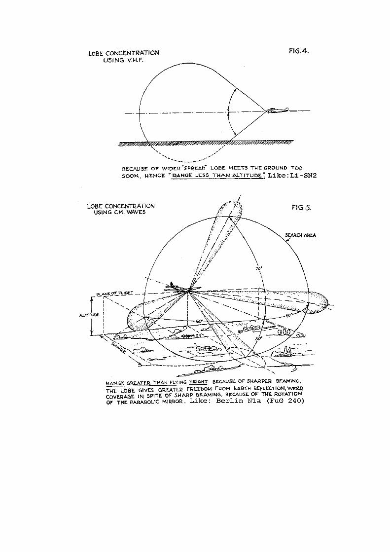
2) Operation. The man in charge of the emergency power unit must devote the greatest attention to its maintenance, as the use of these installations is now becoming more and more necessary. The “Gengas” Generator has already proved its worth in lorries. [and busses and sometimes even private cars, AOB] Failures of the stationary installations must therefore usually be attributed to the maintenance or the insufficient study of the instructions. At the school in Pardubitz [German spelling of Pardubice in the CZ, about 100 km east of Prague, AOB], Pöcking and Köthen, where the maintenance engineers for the emergency power units are trained, supplementary courses have been arranged for “Gengas” operation. If the Company wishes to ensure satisfactory running of the “Gengas” with emergency power, which is getting more and more necessary at present, the most capable men must be sent on the course. Maintenance instructions can never replace the essential tuition of the maintenance personnel. Particularly the Class 1 Radar Sites where there are power units of 30, 60 and 120 kVA, the Site Commander must select the most capable man, because such power units really presents a small power station. Only by correct handling and careful operating can satisfactory running and long life be achieved with the lowest possible wear and tear. The individual power units are by no means prototypes, but machines which have been built after years of experience and have already proved themselves. If the emergency power supply at a site does not work properly, therefore, in 90% of cases it is the fault of the maintenance man, and so of the Site Commander, who has not selected a suitable man with sufficient care. C. NEW DEVELOPMENTS IN AIRBORNE RADAR. I. AIRBORNE SEARCH SETS. (A.I.). Up till now, nightfighting has depend almost entirely on Lichtenstein SN2 [ Li-SN2, AOB]. Because of the enemy’s comprehensive jamming operations, effectual use of the Lichtenstein SN2, especially in the West, cannot be relied upon. In order to equip units, within a reasonable time, with useful nightfighting aids, re-equipment with new apparatus must be rushed trough. These apparatus will work on new frequency bands, and, particularly, with new procedures, and so ensure operation free jamming, at any rate for certain time. Later on, the introduction of the following nightfighter A.I. sets is to be expected:- 1) Neptun VR (FuG 218VR). Neptun VR represents a further development of Neptun J. In the final version the set can be set to any one of 6 different spot frequencies in the V.H.F. [UKW, maybe Meterwellen-Bereich, AOB] band during flight. Remote control of the frequency change is not provided on the first sets. The apparatuses are provided with various HF attachments, which facilitate adjustments to 6 alternative frequencies on the ground. The conversion can be carried out by the ground personnel and takes a few hours.

Up to the present, ranges in flight have varied between 5 and 6 km. [mostly determined by the ground return signal which is approximately equal to the actual flying altitude, AOB] The set can be used simultaneously as a forward search apparatus and tail warning apparatus. For the forward aerial, a somewhat smaller horn aerial, similar to the Lichtenstein SN2, is used. The set weighs about 60 kg [I guess, including rotating power convertor, AOB] The transmitting power is about 1.5 kW. A very greatly improved range is expected by using a steppedup transmitter (Neptun GR). This transmitter has about 10 times the power. The first Neptun VR’s are already being installed. The aircraft to have them installed immediately are:- Ju 88 G6, He 219 A7, Me 110 GH, Do 335 A6, Me 262, Ar 234. 2) Berlin N 1a (FuG 240). In the development of the Berlin we have gone over to a new procedure and a new frequency band. [9 cm, AOB] This new solution makes the picking up of targets at “ranges greater than flying height” possible. This is achieved by a sharp beaming of the search lobes, which has been made possible by going over into the centimetre band. By means of this narrow beaming, freedom from ground reflection is still attained even at low flying heights, in contrast to search apparatus on the V.H.F. band. (See figures 3 and 4) In order to obtain a wide coverage in spite of the narrow beaming, the lobe is rotated so that it scans a wider field. Rotatable paraboloid reflectors with rotary dipoles [constituting a pencil-beam, the translator might have misinterpreted the German text. When we refer to Trenkle, then the parabolic mirror please in the aircraft nose section was steered by means of a joy-stick. It might have, however, been possible that the antenna arrangement could search automatically forward sectors, AOB] are used in the turret. The angle of rotation [sweeping the antenna dish, AOB] to + 60° in azimuth, 70° upwards and 30° downwards. After picking up a target, the mirror deflection and thus the deflection of the target, is shown on the indicator. Searching for the following targets is difficult in the present version. Experiments are in progress which should result in another solution of the necessary rotation by the search lobes scanning the field. In experiments up till now ranges of 5 km. have been reached. The ratio between range and flying height amounts to about 2.5:1. The set weighs 180 kg. without cables so that at the moment it van only be used in Ju 88’s. [maybe including the quite heavy rotating convertor for 80 V ac 500 Hz, a rather heavy device, which by the way, was of equally design as in British H2S systems, AOB] Only 100 of these sets will be completed; they should be delivered during the first third of 1945. [to my knowledge, 3 systems were successfully operational in March/April 1945, AOB] The first aircraft with Berlin N 1a are now coming into operation. [maybe at Delmenhorst air field, AOB] Installation in Ju 88 G6 is expected shortly. II. Homers. 1) Flensburg (FuG 227). As “Monica” is hardly ever being switched on by the enemy at present, Flensburg I is not being further installed, except for a few sets. Because of this, several new frequencies have been developed for “Flensburg”. Flensburg II. 1.7 – 2.5 m. is the wavelength used for homing on enemy jammers, in particular Freya jammers (Insel A, B) and the airborne jammers against Jagdschloss and Jagdhütte. 20 sets have been completed and are present on test at Werneuchen.
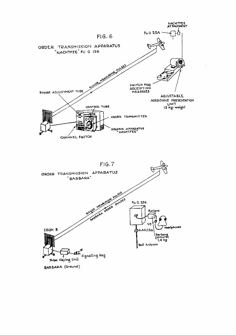
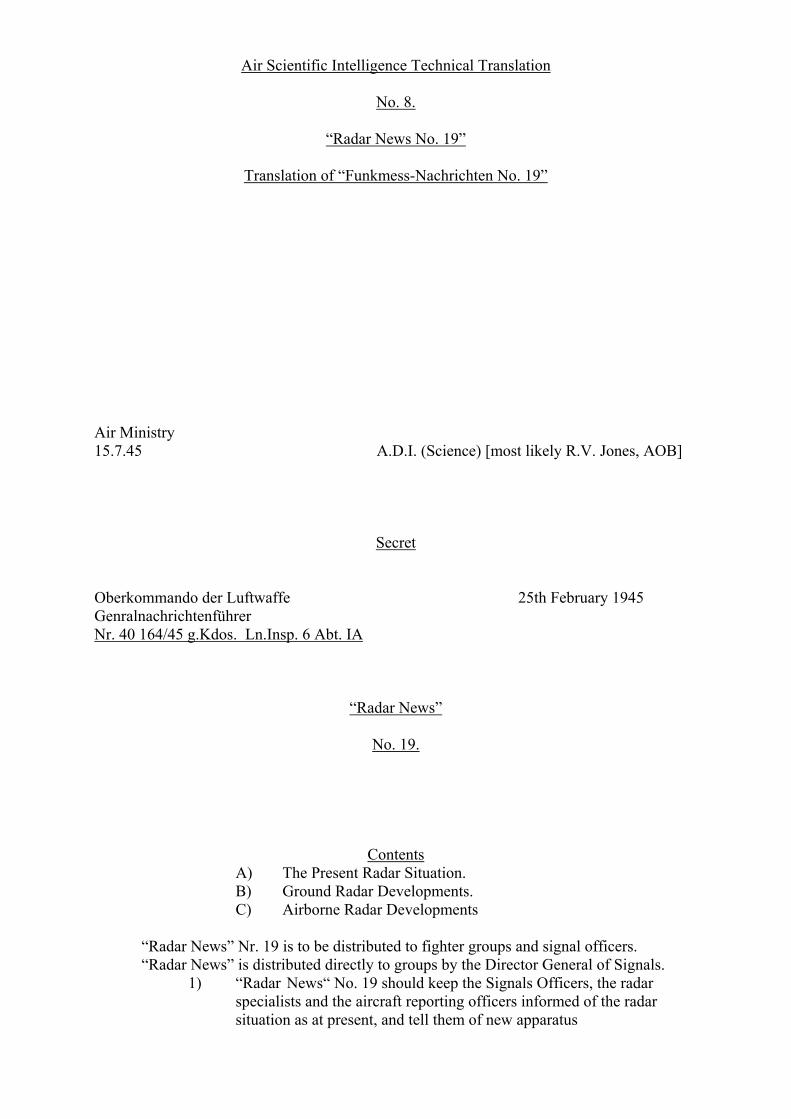
Flensburg III, IV. For homing on jammers of the SN2 spot frequencies and Freya C Insel the wavelengths used are 2.5 – 3.8 – 5 m. Aerial development is not yet finished. Flensburg V and VI. In the 25 cm. and 50 cm. bands for homing onto Würzburg and Panorama jammers. Apparatus and aerials in development. 2) Naxos (Fug 350 Z) [wrongly typed 351, which is Korfu. Why they do not mention 350 Zc, which is the GAF modified version of 1944, I don’t know, AOB] There are a number of improvements and new developments which will be shortly be coming into operation. Naxos ZD. Covers the 9 cm. and 3 cm. bands. Rotating aerial with polyrod [Stielstrahler, AOB] antenna and parabolic reflectors. Amplifier and presentation in a single unit. [presentation unit is maybe equal to FuG 350 Zc, AOB] In the future all Naxos sets will be issued as combined type Naxos ZD. Naxos ZD covers “Rotterdam”, “Frankfurt”, “Grille” and Village Inn, as well as “Rotterdam X” and Meddo” in the 3 cm. band. Besides this our own centimetre sets, which are not yet on different spot frequencies (Berlin N 1a and A), are covered. (Operating notes are in preparation.) Naxos R (Rückwärts = Backward Looking). A warning attachment, covers every cm. apparatus in the 9 cm. band. Range of 5 km., no D/F, two rod aerials above and below. A warning attachment Naxos RX in the 3 cm. band is in preparation. Tail warning in the Naxos presentation units comes up as a central spot of light. Naxos tail warning attachment serves only as an auxiliary or preliminary warning, so, as soon as anything is picked up, switch over to the SN2 R ![R = Rückwärts, AOB] Naxos ZR. Naxos Z with warning attachment Naxos R and selective switching between the homing aerial and the warning aerials. Combined indication comes up on the Naxos presentation unit. RECOGNITION APPARATUS. Erstling (FuG 25a): New Developments. 1) “Red Erstling”. + AAG –Red has fixed tuning, any adjustment by the operators is forbidden. Only electrically matched cables are delivered, so that the installation is considerably simplified. “Red Erstling” will contain the new coding unit (Schaltmühle)9, which ought to have come out in the autumn of last year [1944, AOB], but which had to be modified for 9 +AAG = Antenne Anpassungsgerät 25a = aerial matching unit. Schaltmühle = the coding module which generates the transponder coded response.
matching to the Jagdschloss, and so was delayed. For Jagdschloss I.F.F. it is essential that one recognition signal is given at least at every second revolution of the Jagdschloss aerial. This necessitates a long dash of about 6 seconds by the Erstling coding unit. [Schaltmühle, AOB] This long dash serves at the same time for D/F-ing in Egon control. The tempo of the recognition letter is half as fast as in the former coding units. Instructions regarding the new recognition letters are being prepared. 2) “Green Erstling” (FuG 25a). 1.98 / 2.52 m.; serves as a reserve wavelength for frequency changing during enemy jamming. It also serves for “Erstling” control if separation between recognition working on the old “Erstling” frequency and control working on the “Green” frequencies becomes necessary. On the ground, provision is made for this change of frequency of the EGON-B-Set; it can work equally well on the old frequency as on the “Green”. IV. ORDER TRANSMITTER APPARATUS. (KOMMANDOÜBERTRAGUNGSGERÄT) All control of aircraft is carried out by commands passing from ground-to-air. In the normal way, this is done by W/T or R/T traffic on FuG 10, 15, 16, 17 and so on.10 If this traffic is jammed, control can be carried out with the following apparatus:- 1) “Nachtfee” (FuG 136). Airborne attachment to the “Erstling” receiver (weight 12 kg.), ground attachment to the “Egon” transmitter, needing two operators. Transmission of 16 visual signals which are read off on a cathode ray tube in the aircraft. The apparatus is only suitable for two-seater aircraft, as a continuous intensive watch has to be kept on the visual indicator. Transmission of commands is only possible to an aircraft which flies in the lobe of the ground apparatus [EGON-B station, AOB]. Owing to interruptions in production, it is not possible to give a date for delivery. 2) Barbara (FuG 138). Consists of an attachment to the to the “Erstling” receiver in the aircraft, (weight 2 kg.), and a keying attachment to the “Egon” transmitter on the ground. Audible signals (Morse characteristics) make it possible to use the apparatus for single-seater aircraft, if the pilot is able to read simple Morse code groups. As in the “Nachtfee”, transmission of commands is only possible when the aircraft is flying in a lobe of the ground installation. [EGON-B, AOB] Delivery dates cannot be given at the moment, owing to interruptions in the manufacture. Further order transmitting sets are under development, but cannot be expected to come into use for some time. 10W/T = Morse wireless signals; R/T = voice communications. FuG10 was mostly used for long distance Communications. FuG15 was hardly available. Most air traffic was commenced by FuG 16 and some with FuG17.