
RADAR HANDBOOK Editor in Chief MERRILL I. · PDF fileRADAR HANDBOOK Editor in Chief MERRILL I....
36
RADAR HANDBOOK Editor in Chief MERRILL I. SKOLNIK Second Edition Boston, Massachusetts Burr Ridge, Illinois Dubuque, Iowa Madison, Wisconsin New York, New York San Francisco, California St. Louis, Missouri
Transcript of RADAR HANDBOOK Editor in Chief MERRILL I. · PDF fileRADAR HANDBOOK Editor in Chief MERRILL I....

RADAR
HANDBOOK
Editor in Chief
MERRILL I. SKOLNIK
Second Edition
Boston, Massachusetts Burr Ridge, IllinoisDubuque, Iowa Madison, Wisconsin New York, New York
San Francisco, California St. Louis, Missouri

Library of Congress Cataloging-in-Publication Data
Radar handbook / editor in chief, Merrill I. Skolnik. — 2nd ed.p. cm.Includes index.ISBN 0-07-057913-X1. Radar—Handbooks, manuals, etc. I. Skolnik, Merrill
I. (Merrill Ivan), date.TK6575.R262 1990621.3848—dc20 89-35217
McGraw-HillA Division of The McGraw-Hill Companies
Copyright © 1990 by McGraw-Hill, Inc. All rights reserved. Printed in theUnited States of America. Except as permitted under the United StatesCopyright Act of 1976, no part of this publication may be reproduced ordistributed in any form or by any means, or stored in a data base orretrieval system, without the prior written permission of the publisher.Chapters 8, 13, and 24 were prepared by the contributors as part of theiremployment by the United States government and are not subject tocopyright.
12 1314 15 16 17 18 19 BKM BKM 0 9 8 7 6 5 4 3 2
ISBN O - O T - Q S V T I B - X
The editors for this book were Daniel A. Gonneau and Beatrice E.Eckes, the designer was Naomi Auerbach, and the production supervisorwas Dianne Walber. It was set in Times Roman by the McGraw-HillPublishing Company Professional & Reference Division compositionunit.
Information contained in this work has been obtained byMcGraw-Hill, Inc., from sources believed to be reliable. However,neither McGraw-Hill nor its authors guarantees the accuracy orcompleteness of any information published herein and neitherMcGraw-Hill nor its authors shall be responsible for any errors,omissions, or damages arising out of use of this information. Thiswork is published with the understanding that McGraw-Hill andits authors are supplying information but are not attempting torender engineering or other professional services. If such servicesare required, the assistance of an appropriate professional shouldbe sought.
CONTRIBUTORS
Lament V. Blake, Electronics Consultant (CHAPTER 2)
Michael T. Borkowski, Raytheon Company (CHAPTER 5)
Leopold J. Cantafio, Space and Technology Group TRW (CHAPTER 22)
Theodore C. Cheston, Naval Research Laboratory (CHAPTER 7)
L. J. Cutrona, Sarcutron, Inc. (CHAPTER 21)
Daniel Davis, Electronic Systems Group, Westinghouse Electric Corporation(CHAPTER 6)
Gary E. Evans, Electronic Systems Group, Westinghouse Electric Corporation(CHAPTER 6)
A. Farina, Radar Department, Selenia S.p.A., Italy (CHAPTER 9)
Edward C. Farnett, RCA Electronics Systems Department, GE Aerospace (CHAPTER 10)
Joe Frank, Technology Service Corporation (CHAPTER 7)
V. Gregers-Hansen, Equipment Division, Raytheon Company (CHAPTER 15)
J. M. Headrick, Naval Research Laboratory (CHAPTER 24)
Dean D. Howard, Locus, Inc., a subsidiary of Kaman Corp. (CHAPTER 18)
Alex Ivanov, Missile Systems Division, Raytheon Company (CHAPTER 19)
Eugene F. Knott, The Boeing Company (CHAPTER 11)
William H. Long, Westinghouse Electric Corporation (CHAPTER 17)
David H. Mooney, Westinghouse Electric Corporation (CHAPTER 17)
Richard K. Moore, The University of Kansas (CHAPTER 12)
David J. Murrow, General Electric Company (CHAPTER 20)
William K. Saunders, formerly of Harry Diamond Laboratories (CHAPTER 14)
Helmut E. Schrank, Electronics Systems Group, Westinghouse Electric Corporation(CHAPTER 6)
Robert J. Serafin, National Center for Atmospheric Research (CHAPTER 23)
William W. Shrader, Equipment Division, Raytheon Company (CHAPTER 15)
William A. Skillman, Westinghouse Electric Corporation (CHAPTER 17)
Merrill I. Skolnik, Naval Research Laboratory (CHAPTER 1)
Fred M. Staudaher, Naval Research Laboratory (CHAPTER 16)
George H. Stevens, RCA Electronics Systems Department, GE Aerospace(CHAPTER 10)
John W. Taylor, Jr., Westinghouse Electric Corporation (CHAPTER 3)
G. V. Trunk, Naval Research Laboratory (CHAPTER 8)
T. A. Weil, Equipment Division, Raytheon Company (CHAPTER 4)
Lewis B. Wetzel, Naval Research Laboratory (CHAPTER 13)
Nicholas J. Willis, Technology Service Corporation (CHAPTER 25)

PREFACE
This edition has been thoroughly revised to reflect the advances made inradar over the past two decades. There are many new topics not found inthe original, and over half of the 25 chapters were written by authors whodid not participate in the first edition. The continued growth in radarcapability and applications is reflected in much of the new materialincluded in this second edition. The following are some of the many newradar advances that have occurred since the original edition (listed in noparticular order):
• The use of digital techniques that allow sophisticated signal processingin MTI and pulse doppler radars, as well as digital data processing toperform automatic detection and tracking.
• The use of the doppler filter bank and the clutter map in MTI radar.• The reduced dependency on operators for extracting information from
a radar and the incorporation of CFAR in automatic detection andtracking systems.
• The emergence of the analog SAW dispersive delay line as thepreferred technique for wideband (high-resolution) pulse compression;the use of digital processing for the pulse compression filter when thebandwidth permits; and the introduction of Stretch pulse compression,which allows high resolution, over a limited range interval withconsiderably reduced processing bandwidth.
• The increased use of 3D radar for military applications.• The introduction of the ultralow-sidelobe antenna for airborne pulse
doppler radar and, later, for ECCM.• The replacement of the parabolic reflector antenna with the planar-
aperture array antenna for 3D radar, ultralow-sidelobe antennas, andairborne radar.
• The high-power solid-state transmitter that consists of many transistormodules distributed on the rows of a 3D radar (such as the AN/TPS-59),or employed at the elements of a phased array (as in PAVE PAWS), orconfigured as a transmitter for a conventional radar (as in the AN/SPS-40 or the Canadian ATC radar known as RAMP).
• The serial production of phased arrays for the Patriot, Aegis, PAVEPAWS, and Bl-B radar systems.

• The interest in the radar cross section of targets brought about by theattempts to reduce the cross section of military vehicles; and advancesin computer methods for predicting the cross section of complextargets.
• The increased capability of military airborne radar (airborne intercept,AW ACS, and AEW) due to advances in components and technologythat permitted the application of AMTI and pulse doppler to thedetection of aircraft in the midst of large clutter.
• The use of radar in space for rendezvous and landing, remote sensing ofthe earth's environment, planetary exploration, and the detection oftargets on the oceans of the world.
• The use of semiactive radar for the guidance of military missilesystems.
• The extraction of the doppler frequency shift in meteorological radarsthat permits the recognition of hazardous weather phenomena notpossible with previous weather radars.
• The use of radar operating in the HF portion of the spectrum for long-range over-the-horizon detection of aircraft, ships, and missiles, as wellas to provide the direction of the surface winds and the sea state overwide areas of the ocean.
• The development of electronic counter-countermeasures (ECCM) inmilitary radars to thwart attempts to negate radar capability by hostileelectronic radiations.
• The increased range resolution and doppler resolution in syntheticaperture radars (SAR) for the imaging of a scene, the use of inverseSAR (ISAR) for the imaging of targets, and the replacement of opticalprocessing with digital processing for SAR imaging.
• The adaptive antenna for application in sidelobe cancelers (as anECCM) and AMTI radar.
• The use of computers to reliably and quickly predict the capability andcoverage of radar systems in the real environment.
The purpose of the above listing is to indicate that radar is dynamic.Not all the new advances made since the first edition of this handbook arelisted, nor does the list include all the new material discussed in thisedition. There continue to be significant advances in the application ofnew technology and in the appearance of new applications. Radar growsand is viable since it satisfies important societal, economic, and militaryneeds. It has no serious competitor for most of its many applications.
The size of this edition of the handbook is smaller than the originaledition. This is more an indication of the problems involved in technicalbook publishing rather than problems with the health of radar or the

availability of material to include. It was not an easy task to constrain thechapter authors to a limited page budget, and I am appreciative of theirefforts to keep the size of their chapters within the allocated number ofpages. It would have been easy to double the size of this edition evenwithout increasing the number of chapters. The limitation on size was oneof the reasons a number of chapters found in the first edition do notappear here. Some of the omitted chapters were concerned with subjectsfor which there is not as much interest as there had been or whosetechnology has not advanced as much as other areas of radar. It is withsome regret that 16 of the chapters in the original could not be included inthis second edition.
As in the first edition, no attempt was made to utilize a standardnotation throughout the book. Each particular subspecialty of radarseems to have developed its own nomenclature, and it is not appropriatein a book such as this to force authors to use notation that is foreign totheir field even though it might be commonplace in some other aspect ofradar.
Each chapter author was instructed to assume that the average readerhas a general knowledge of radar but is not necessarily an expert in theparticular subject covered by the chapter.
After a general introduction to radar in Chap. 1, there is a review of themethodology for predicting the range of a radar that has evolved over theyears. This is followed by several chapters on the major subsystems of aradar: the receiver, transmitter, solid-state transmitters, reflector anten-nas, phased array antennas, data processing, ECCM, and pulse compres-sion. Next are discussions of the target cross section and the nature of theradar echoes from the ground and the sea. The various types of radarsystems are then discussed: CW and FM-CW, MTI, AMTI, pulsedoppler, tracking, missile guidance, height finding and 3D, and syntheticaperture radar. This is followed by three specialized examples of radarthat have their own unique character: radar in space, meteorological(weather) radar, and HE over-the horizon radar. The book closes with atreatment of the bistatic radar, which was the first type of radar exploredduring the onset of radar development in the 1930s.
I would hope that readers who refer in their own writings to materialfrom this book do so by chapter author and title and not by citing just the"Radar Handbook." This will give proper credit to the individual authorswho created the work.
It is with much pleasure that I acknowledge the contributions of theindividual chapter authors. I enjoyed working with these talented radarengineers and having the opportunity to learn so much from my associa-tion with them. A handbook such as this exists only because of thededicated efforts of the many experts who took the time and energy to

prepare the individual chapters. I appreciate their hard work in commit-ting to writing their knowledge and experience, and I am grateful that theyhave shared this with us.
Merrill Skolnik

ABOUT THE EDITOR IN CHIEF
Merrill I. Skolnik, known worldwide for his leadership in radar research and de-velopment, has been affiliated with the Johns Hopkins Radiation Laboratory,Sylvania, MIT Lincoln Laboratory, the Research Division of Electronic Commu-nications Inc., the Institute for Defense Analyses, and the U.S. Naval ResearchLaboratory. He received his doctorate in electrical engineering from JohnsHopkins University, where he also earned B.E. and M.S.E. degrees. He is theauthor of the leading college textbook on radar, Introduction to Radar Systems(McGraw-Hill), now in its second edition, and the editor of Radar Applications.
He is a member of the National Academy of Engineering, a Fellow of theIEEE, and has served as editor of the Proceedings of the IEEE.

This page has been reformatted by Knovel to provide easier navigation.
v
Contents
Contributors ..................................................................... xx
Preface ............................................................................ xxi
1. An Introduction to Radar ........................................ 1.1 1.1 Description of Radar ............................................... 1.1
Radar Block Diagram ......................................... 1.2 1.2 Radar Equation ....................................................... 1.6
Tracking ............................................................ 1.8 Volume Search .................................................. 1.8 Jamming ............................................................ 1.9 Clutter ............................................................... 1.10
1.3 Information Available from the Radar Echo ............ 1.10 Range ............................................................... 1.11 Radial Velocity ................................................... 1.11 Angular Direction ............................................... 1.12 Size ................................................................... 1.12 Shape ................................................................ 1.12 Other Target Measurements .............................. 1.13
1.4 Radar Frequencies ................................................. 1.13 HF (3 to 30 MHz) ............................................... 1.15 VHF (30 to 300 MHz) ......................................... 1.15 UHF (300 to 1000 MHz) ..................................... 1.16 L Band (1.0 to 2.0 GHz) ..................................... 1.16 S Band (2.0 to 4.0 GHz) ..................................... 1.16
This page has been reformatted by Knovel to provide easier navigation.
vi Contents
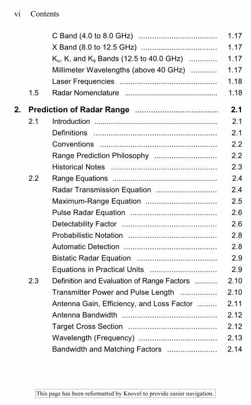
C Band (4.0 to 8.0 GHz) .................................... 1.17 X Band (8.0 to 12.5 GHz) ................................... 1.17 Ku, K, and Ka Bands (12.5 to 40.0 GHz) ............. 1.17 Millimeter Wavelengths (above 40 GHz) ............ 1.17 Laser Frequencies ............................................. 1.18
1.5 Radar Nomenclature .............................................. 1.18
2. Prediction of Radar Range ..................................... 2.1 2.1 Introduction ............................................................. 2.1
Definitions ......................................................... 2.1 Conventions ...................................................... 2.2 Range Prediction Philosophy ............................. 2.2 Historical Notes ................................................. 2.3
2.2 Range Equations .................................................... 2.4 Radar Transmission Equation ............................ 2.4 Maximum-Range Equation ................................. 2.5 Pulse Radar Equation ........................................ 2.6 Detectability Factor ............................................ 2.6 Probabilistic Notation ......................................... 2.8 Automatic Detection ........................................... 2.8 Bistatic Radar Equation ..................................... 2.9 Equations in Practical Units ............................... 2.9
2.3 Definition and Evaluation of Range Factors ........... 2.10 Transmitter Power and Pulse Length ................. 2.10 Antenna Gain, Efficiency, and Loss Factor ......... 2.11 Antenna Bandwidth ............................................ 2.12 Target Cross Section ......................................... 2.12 Wavelength (Frequency) .................................... 2.13 Bandwidth and Matching Factors ....................... 2.14
This page has been reformatted by Knovel to provide easier navigation.
Contents vii
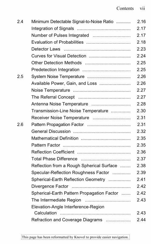
2.4 Minimum Detectable Signal-to-Noise Ratio ............ 2.16 Integration of Signals ......................................... 2.17 Number of Pulses Integrated ............................. 2.17 Evaluation of Probabilities .................................. 2.18 Detector Laws ................................................... 2.23 Curves for Visual Detection ................................ 2.24 Other Detection Methods ................................... 2.25 Predetection Integration ..................................... 2.25
2.5 System Noise Temperature .................................... 2.26 Available Power, Gain, and Loss ........................ 2.26 Noise Temperature ............................................ 2.27 The Referral Concept ........................................ 2.27 Antenna Noise Temperature .............................. 2.28 Transmission-Line Noise Temperature ............... 2.30 Receiver Noise Temperature ............................. 2.31
2.6 Pattern Propagation Factor .................................... 2.31 General Discussion ............................................ 2.32 Mathematical Definition ...................................... 2.35 Pattern Factor .................................................... 2.35 Reflection Coefficient ......................................... 2.36 Total Phase Difference ...................................... 2.37 Reflection from a Rough Spherical Surface ........ 2.38 Specular-Reflection Roughness Factor .............. 2.39 Spherical-Earth Reflection Geometry ................. 2.41 Divergence Factor ............................................. 2.42 Spherical-Earth Pattern Propagation Factor ....... 2.42 The Intermediate Region ................................... 2.43 Elevation-Angle Interference-Region
Calculation ...................................................... 2.43 Refraction and Coverage Diagrams ................... 2.44
This page has been reformatted by Knovel to provide easier navigation.
viii Contents
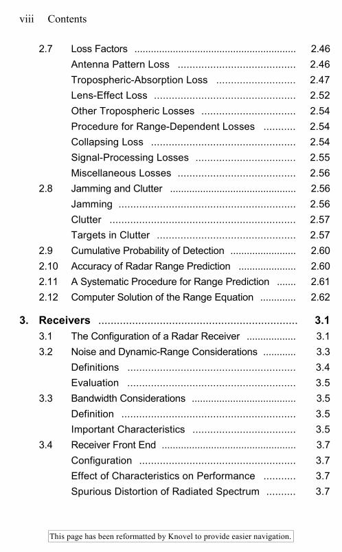
2.7 Loss Factors ........................................................... 2.46 Antenna Pattern Loss ........................................ 2.46 Tropospheric-Absorption Loss ........................... 2.47 Lens-Effect Loss ................................................ 2.52 Other Tropospheric Losses ................................ 2.54 Procedure for Range-Dependent Losses ........... 2.54 Collapsing Loss ................................................. 2.54 Signal-Processing Losses .................................. 2.55 Miscellaneous Losses ........................................ 2.56
2.8 Jamming and Clutter .............................................. 2.56 Jamming ............................................................ 2.56 Clutter ............................................................... 2.57 Targets in Clutter ............................................... 2.57
2.9 Cumulative Probability of Detection ........................ 2.60 2.10 Accuracy of Radar Range Prediction ..................... 2.60 2.11 A Systematic Procedure for Range Prediction ....... 2.61 2.12 Computer Solution of the Range Equation ............. 2.62
3. Receivers ................................................................. 3.1 3.1 The Configuration of a Radar Receiver .................. 3.1 3.2 Noise and Dynamic-Range Considerations ............ 3.3
Definitions ......................................................... 3.4 Evaluation ......................................................... 3.5
3.3 Bandwidth Considerations ...................................... 3.5 Definition ........................................................... 3.5 Important Characteristics ................................... 3.5
3.4 Receiver Front End ................................................. 3.7 Configuration ..................................................... 3.7 Effect of Characteristics on Performance ........... 3.7 Spurious Distortion of Radiated Spectrum .......... 3.7

This page has been reformatted by Knovel to provide easier navigation.
Contents ix
Spurious Responses of Mixers ........................... 3.8 Characteristics of Amplifiers and Mixers ............. 3.11
3.5 Local Oscillators ..................................................... 3.11 Functions of the Local Oscillator ........................ 3.11 Stalo Instability .................................................. 3.12 Coho and Timing Instability ................................ 3.16 Total Radar Instability ........................................ 3.16
3.6 Gain-Controlled Amplifiers ...................................... 3.17 Sensitivity Time Control (STC) ........................... 3.17 Clutter Map Automatic Gain Control ................... 3.18 Automatic Noise-Level Control ........................... 3.19
3.7 Filtering ................................................................... 3.19 Filtering of the Entire Radar System ................... 3.19 Definitions ......................................................... 3.20 Approximations to Matched Filters ..................... 3.21 Filtering Problems Associated with Mixer
Spurious Responses ....................................... 3.22 3.8 Logarithmic Devices ............................................... 3.25
Characteristics ................................................... 3.25 Analog Logarithmic Devices ............................... 3.27 Digital Logarithm ................................................ 3.28 Digital Log Power Combiner .............................. 3.29
3.9 IF Limiters ............................................................... 3.30 Applications ....................................................... 3.30 Characteristics ................................................... 3.30
3.10 Phase Detectors and Synchronous Detectors ........ 3.32 Definitions and Characteristics ........................... 3.32 Applications ....................................................... 3.33 Examples of Phase Detectors ............................ 3.36 Analog-to-Digital Phase Detector ....................... 3.37

This page has been reformatted by Knovel to provide easier navigation.
x Contents
Digital Phase Detector ....................................... 3.38 3.11 Analog-to-Digital Converter .................................... 3.38
Applications ....................................................... 3.38 Formats ............................................................. 3.39 Synchronization ................................................. 3.39 Performance Characteristics .............................. 3.40 Multiplexing ....................................................... 3.41
3.12 I/Q Distortion Effects and Compensation Methods .................................................................. 3.41 Gain or Phase Unbalance .................................. 3.41 Time Delay and Pulse Shape Unbalance ........... 3.43 Nonlinearity in I and Q Channels ........................ 3.45 DC Offset .......................................................... 3.46
3.13 CFAR Detection Processes .................................... 3.46 Application ......................................................... 3.46 Amplitude-Discrimination CFAR (Cell-
Averaging CFAR) ............................................ 3.47 Phase-Discrimination CFAR (CPACS) ............... 3.49 Effect on Range Resolution and Azimuth
Accuracy ......................................................... 3.50 Clutter Map CFAR ............................................. 3.53
3.14 Diplex Operation ..................................................... 3.54 Benefits ............................................................. 3.54 Recommended Implementation .......................... 3.54
4. Transmitters ............................................................ 4.1 4.1 Introduction ............................................................. 4.1
The Transmitter as Part of a Pulsed Radar System ............................................................ 4.1
Why So Much Power? ....................................... 4.2 Why Pulsed? ..................................................... 4.3

This page has been reformatted by Knovel to provide easier navigation.
Contents xi
4.2 Magnetron Transmitters ......................................... 4.5 Limitations ......................................................... 4.5 Magnetron Features .......................................... 4.6 Common Problems ............................................ 4.7
4.3 Amplifier Chain Transmitters .................................. 4.9 Oscillator versus Amplifier ................................. 4.9 Amplifier Chains: Special Considerations ........... 4.10
4.4 RF Amplifier Tubes ................................................. 4.12 Crossed-Field Amplifiers (CFAs) ........................ 4.12 Klystrons ........................................................... 4.14 Traveling-Wave Tubes (TWTs) .......................... 4.15 RF Tube Selection ............................................. 4.17 RF Tube Power Capabilities .............................. 4.21
4.5 Combining and Arraying ......................................... 4.22 Hybrid Combining (or Magic T) .......................... 4.22 Phased Arrays ................................................... 4.23
4.6 Transmitter Stability Requirements ........................ 4.25 Pulsed MTI Systems .......................................... 4.25 Pulse Compression Systems ............................. 4.27 Stability Improvement by Feedback or
Feedforward .................................................... 4.30 4.7 Transmitter Spectrum Control ................................ 4.31
Reduction of Spurious Outputs .......................... 4.31 Reduction of Spectrum Amplitude Exceeding
(sin x)/x ........................................................... 4.31 Improvement over (sin x)/x by Means of
Shaped Pulses ................................................ 4.31 4.8 Pulse Modulators .................................................... 4.32
Line-Type Modulators ........................................ 4.33 Active-Switch Modulators ................................... 4.35
This page has been reformatted by Knovel to provide easier navigation.
xii Contents
Grid Pulsers ...................................................... 4.39 4.9 High-Voltage Crowbars, Regulators, and
Power Supplies ....................................................... 4.39 Crowbars ........................................................... 4.40 Regulators ......................................................... 4.41 High-Voltage Power Supplies ............................. 4.41
5. Solid-State Transmitters ......................................... 5.1 5.1 Introduction ............................................................. 5.1 5.2 Solid-State Microwave Power Generation .............. 5.4
Microwave Bipolar Power Transistors ................ 5.5 Microwave Field-Effect Transistors (FETs) ......... 5.9 Millimeter-Wave Solid-State Power Sources ...... 5.11
5.3 Solid-State Microwave Design ................................ 5.12 High-Power Amplifier Design ............................. 5.13 Phased Array Transceiver Module Design .......... 5.16 Microwave Monolithic Integrated Circuits ........... 5.16 Transceiver Module Performance
Characteristics ................................................ 5.18 5.4 Transmitter System Design .................................... 5.21
Performance Sensitivities .................................. 5.21 Power Combining .............................................. 5.23 Solid-State Transmitter Design Examples .......... 5.23
6. Reflector Antennas ................................................. 6.1 6.1 Introduction ............................................................. 6.1
Role of the Antenna ........................................... 6.1 Beam Scanning and Target Tracking ................. 6.1 Height Finding ................................................... 6.2 Classification of Antennas .................................. 6.2
This page has been reformatted by Knovel to provide easier navigation.
Contents xiii
6.2 Basic Principles and Parameters ............................ 6.2 Reciprocity ........................................................ 6.2 Gain, Directivity, and Effective Aperture ............. 6.3 Radiation Patterns ............................................. 6.5
6.3 Types of Antennas .................................................. 6.10 Paraboloidal Reflector Antennas ........................ 6.12 Parabolic-Cylinder Antenna ............................... 6.15 Shaped Reflectors ............................................. 6.17 Multiple Beams and Extended Feeds ................. 6.19 Monopulse Feeds .............................................. 6.21 Multiple-Reflector Antennas ............................... 6.23 Special-Purpose Reflectors ................................ 6.26
6.4 Feeds ...................................................................... 6.26 6.5 Reflector Antenna Analysis .................................... 6.27 6.6 Shaped-Beam Antennas ........................................ 6.30
Gain Estimation ................................................. 6.31 Shaped-Beam Antenna Design .......................... 6.32 Antenna Size ..................................................... 6.33 Accuracy ........................................................... 6.34
6.7 Design Considerations ........................................... 6.34 Feed Blockage .................................................. 6.34 Feed Spillover and Diffraction ............................ 6.37 Surface Leakage ............................................... 6.40
6.8 Mechanical Considerations .................................... 6.40 6.9 Radomes ................................................................ 6.44
Types of Radomes and General Considerations ................................................ 6.44
Environmental Effects ........................................ 6.45 Airborne and Missile Radomes .......................... 6.46 Ground and Shipboard Radomes ....................... 6.47
This page has been reformatted by Knovel to provide easier navigation.
xiv Contents
Other Radome Effects ....................................... 6.48 6.10 Antenna Testing ..................................................... 6.52
Pattern Test Ranges .......................................... 6.52 Elevated Ranges ............................................... 6.53 Ground Ranges ................................................. 6.55 Compact Ranges ............................................... 6.56 Near-Field Ranges ............................................. 6.57 Miscellaneous Tests .......................................... 6.59
7. Phased Array Radar Antennas .............................. 7.1 7.1 Introduction ............................................................. 7.1
Phased Array Radars ........................................ 7.1 Scanning of Arrays ............................................ 7.7
7.2 Array Theory ........................................................... 7.10 7.3 Planar Arrays and Beam Steering .......................... 7.17
Planar Arrays ..................................................... 7.17 Element-Phasing Calculations ........................... 7.21
7.4 Aperture Matching and Mutual Coupling ................ 7.22 Significance of Aperture Matching ...................... 7.22 Effects of Mutual Coupling ................................. 7.23 Element Pattern ................................................. 7.25 Thinned Arrays .................................................. 7.26 Impedance Variation of Free Space ................... 7.27 Element Impedance ........................................... 7.27 Analytical Techniques ........................................ 7.29 Nonisolating Feeds ............................................ 7.30 Mutual Coupling and Surface Waves ................. 7.31 Array Simulators ................................................ 7.32 Compensation for Scanned Impedance
Variation .......................................................... 7.35

This page has been reformatted by Knovel to provide easier navigation.
Contents xv
Small Arrays ...................................................... 7.35 7.5 Low-Sidelobe Phased Arrays ................................. 7.37
Illumination Functions ........................................ 7.37 Effect of Errors .................................................. 7.38 Random Errors .................................................. 7.39
7.6 Quantization Effects ............................................... 7.43 Phase Quantization ........................................... 7.43 Periodic Errors ................................................... 7.45
7.7 Bandwidth of Phased Arrays .................................. 7.49 Aperture Effects ................................................. 7.49 Feed Effect ........................................................ 7.51 Broad Instantaneous Bandwidth ......................... 7.53 Time-Delay Networks ........................................ 7.56
7.8 Feed Networks (Beamformers) .............................. 7.58 7.9 Phase Shifters ........................................................ 7.63
Diode Phasers ................................................... 7.63 Ferrite Phasers .................................................. 7.64
7.10 Solid-State Modules ............................................... 7.67 7.11 Phased Array Systems ........................................... 7.69
8. Automatic Detection, Tracking, and Sensor Integration ............................................................... 8.1 8.1 Introduction ............................................................. 8.1 8.2 Automatic Detection ............................................... 8.1
Optimal Detector ................................................ 8.2 Practical Detectors ............................................ 8.3 False-Alarm Control ........................................... 8.12 Target Resolution .............................................. 8.21 Detection Summary ........................................... 8.23

This page has been reformatted by Knovel to provide easier navigation.
xvi Contents
8.3 Automatic Tracking ................................................. 8.23 Track-While-Scan Systems ................................ 8.24 Maximum-Likelihood Approaches ...................... 8.38
8.4 Multisensor Integration ........................................... 8.40 Colocated Radar Integration .............................. 8.42 Multisite Radar Integration ................................. 8.43 Unlike-Sensor Integration .................................. 8.44
9. Electronic Counter-Countermeasures .................. 9.1 9.1 Introduction ............................................................. 9.1 9.2 Terminology ............................................................ 9.2 9.3 Electronic Warfare Support Measures .................... 9.2 9.4 Electronic Countermeasures .................................. 9.4 9.5 Objectives and Taxonomy of ECCM
Techniques ............................................................. 9.7 9.6 Antenna-Related ECCM ......................................... 9.7
Sidelobe-Blanking (SLB) System ....................... 9.9 Sidelobe Canceler (SLC) System ....................... 9.11 Adaptive Arrays ................................................. 9.14
9.7 Transmitter-Related ECCM .................................... 9.16 9.8 Receiver-Related ECCM ........................................ 9.18 9.9 Signal-Processing-Related ECCM ......................... 9.19 9.10 Operational-Deployment Techniques ..................... 9.21 9.11 Application of ECCM Techniques ........................... 9.22
Surveillance Radars ........................................... 9.23 Tracking Radars ................................................ 9.25
9.12 ECCM and ECM Efficacy ....................................... 9.28 The Radar Equation in Jamming and Chaff
Conditions ....................................................... 9.29
This page has been reformatted by Knovel to provide easier navigation.
Contents xvii
10. Pulse Compression Radar ..................................... 10.1 10.1 Introduction ............................................................. 10.1 10.2 Factors Affecting Choice of Pulse
Compression System ............................................. 10.3 10.3 Linear FM ............................................................... 10.4 10.4 Nonlinear FM .......................................................... 10.4 10.5 Pulse Compression Devices ................................... 10.6
Digital Pulse Compression ................................. 10.7 Surface-Wave Pulse Compression ..................... 10.10 Other Passive Linear-FM Devices ...................... 10.12 Voltage-Controlled Oscillator ............................. 10.15
10.6 Phase-Coded Waveforms ...................................... 10.15 Optimal Binary Sequences ................................. 10.17 Maximal-Length Sequences ............................... 10.19 Quadratic Residue Sequences ........................... 10.21 Complementary Sequences ............................... 10.21 Implementation of Biphase-Coded Systems ....... 10.22 Doppler Correction ............................................ 10.24 Polyphase Codes .............................................. 10.25
10.7 Time-Frequency-Coded Waveforms ...................... 10.26 10.8 Weighting and Equalization .................................... 10.27
Paired Echoes and Weighting ............................ 10.27 Comparison of Weighting Functions ................... 10.29 Taylor versus Cosine-Squared-Plus-Pedestal
Weighting ........................................................ 10.31 Taylor Weighting with Linear FM ........................ 10.31 Discrete Time Weighting .................................... 10.34 Amplitude and Phase Distortion ......................... 10.34 Equalization ....................................................... 10.36
This page has been reformatted by Knovel to provide easier navigation.
xviii Contents
11. Radar Cross Section ............................................... 11.1 11.1 Introduction ............................................................. 11.1 11.2 The Concept of Echo Power ................................... 11.2
Definition of RCS ............................................... 11.2 Examples of RCS Characteristics ...................... 11.4
11.3 RCS Prediction Techniques ................................... 11.18 Exact Methods ................................................... 11.20 Approximate Methods ........................................ 11.24
11.4 RCS Measurement Techniques ............................. 11.34 General Requirements ....................................... 11.35 Outdoor Test Ranges ........................................ 11.38 Indoor Test Ranges ........................................... 11.39
11.5 Echo Reduction ...................................................... 11.43 Shaping ............................................................. 11.44 Radar Absorbers ............................................... 11.46
11.6 Summary ................................................................ 11.51
12. Ground Echo ........................................................... 12.1 12.1 Introduction ............................................................. 12.1
Relative Importance of Theory and Empiricism ...................................................... 12.3
Available Scattering Information ......................... 12.3 12.2 Parameters Affecting Ground Return ..................... 12.4 12.3 Theoretical Models and Their Limitations ............... 12.6
Descriptions of a Surface ................................... 12.6 Simplified Models .............................................. 12.7 Physical Optics Models ...................................... 12.9 Small-Perturbation and Two-Scale Models ......... 12.10 Other Models ..................................................... 12.12
This page has been reformatted by Knovel to provide easier navigation.
Contents xix
12.4 Fading of Ground Echoes ....................................... 12.12 Fading-Rate Computations ................................ 12.13 Effect of Detection ............................................. 12.16 Moving Target Surfaces ..................................... 12.18
12.5 Measurement Techniques for Ground Return ........ 12.18 CW and FM-CW Systems .................................. 12.18 Range-Measuring Systems ................................ 12.21 CW-Doppler Scatterometers .............................. 12.22 Independent Samples Required for
Measurement Accuracy ................................... 12.23 Near-Vertical Problem ....................................... 12.23 Ground and Helicopter Scatterometers and
Spectrometers ................................................. 12.24 Scattering Coefficient from Images .................... 12.28 Bistatic Measurements ....................................... 12.28
12.6 General Models for Scattering Coefficient (Clutter Models) ...................................................... 12.28
12.7 Scattering Coefficient Data ..................................... 12.35 Effects of Roughness, Moisture Content, and
Vegetation Cover ............................................. 12.35 Soil Moisture ...................................................... 12.39 Vegetation ......................................................... 12.41 Snow ................................................................. 12.42 Sea Ice .............................................................. 12.44
12.8 Imaging Radar Interpretation .................................. 12.45
13. Sea Clutter ............................................................... 13.1 13.1 Introduction ............................................................. 13.1 13.2 Description of the Sea Surface ............................... 13.2
The Wave Spectrum .......................................... 13.3 General Sea Descriptors .................................... 13.5
This page has been reformatted by Knovel to provide easier navigation.
xx Contents
13.3 Empirical Behavior of Sea Clutter ........................... 13.6 Dependence on Wind Speed, Grazing Angle,
and Frequency ................................................ 13.8 The Spectrum of Sea Clutter .............................. 13.21 Other Effects on Sea Clutter .............................. 13.23
13.4 Theories of Sea Clutter ........................................... 13.27 Theories Based on Global Boundary-Value
Problems ......................................................... 13.29 The Composite-Surface Hypothesis ................... 13.32 Scattering by Surface Features .......................... 13.33
13.5 Summary and Conclusions ..................................... 13.35
14. CW and FM Radar ................................................... 14.1 14.1 Introduction and Advantages of CW ....................... 14.1 14.2 Doppler Effect ......................................................... 14.2 14.3 Unmodulated CW Radar ........................................ 14.2
Spectral Spreading ............................................ 14.2 Noise in Sources ............................................... 14.3 Noise from Clutter .............................................. 14.3 Microphonism .................................................... 14.7 Scanning and Target Properties ......................... 14.7
14.4 Sources .................................................................. 14.8 Master Oscillator Power Amplifier (MOPA)
Chains ............................................................. 14.8 Active Stabilization ............................................ 14.8 Stabilization of Power Oscillators ....................... 14.11
14.5 Noise Measurement Technique .............................. 14.11 14.6 Receivers ................................................................ 14.15
RF Amplification ................................................ 14.15 Generation of the Local-Oscillator Signal ........... 14.15

This page has been reformatted by Knovel to provide easier navigation.
Contents xxi
IF Amplifier ........................................................ 14.16 Subcarriers ........................................................ 14.16 Amplication ........................................................ 14.18 Doppler Filter Banks .......................................... 14.18 Doppler Trackers ............................................... 14.18 Constant False-Alarm Rate (CFAR) ................... 14.19
14.7 Minimization of Feedthrough .................................. 14.19 14.8 Miscellaneous CW Radars ..................................... 14.20
CW Proximity Fuzes .......................................... 14.20 Police Radars .................................................... 14.21
14.9 FM Radar ................................................................ 14.21 14.10 Sinusoidal Modulation ............................................ 14.23
Double Sinusoidal Modulation ............................ 14.26 14.11 Triangular and Sawtooth Modulation ...................... 14.27 14.12 Noise Modulation .................................................... 14.28 14.13 Coded Modulations ................................................. 14.29 14.14 Dual Modulation ...................................................... 14.30 14.15 Leakage .................................................................. 14.30 14.16 Performance of FM-CW Systems ........................... 14.31 14.17 Short-Range Systems and Microwave
Proximity Fuzes ...................................................... 14.31 14.18 Altimeters ................................................................ 14.34 14.19 Doppler Navigators ................................................. 14.37 14.20 Personnel Detection Radar and Miscellaneous
FM-CW Systems .................................................... 14.39 14.21 Tailoring the Range Response of FM-CW
Systems .................................................................. 14.41
This page has been reformatted by Knovel to provide easier navigation.
xxii Contents
15. MTI Radar ................................................................. 15.1 15.1 Introduction to MTI Radar ....................................... 15.1
Moving-Target Indicator (MTI) Block Diagram .......................................................... 15.3
Moving-Target Detector (MTD) Block Diagram .......................................................... 15.5
15.2 Clutter Filter Response to Moving Targets ............. 15.7 15.3 Clutter Characteristics ............................................ 15.8
Spectral Characteristics ..................................... 15.8 Amplitude Characteristics .................................. 15.10
15.4 Definitions ............................................................... 15.11 Improvement Factors (I) ..................................... 15.11 Signal-to-Clutter Ratio Improvement (ISCR) ......... 15.11 Subclutter Visibility (SCV) .................................. 15.13 Interclutter Visibility (ICV) ................................... 15.13 Filter Mismatch Loss .......................................... 15.14 Clutter Visibility Factor (VOC) .............................. 15.14
15.5 Improvement Factor Calculations ........................... 15.14 15.6 Optimum Design of Clutter Filters ........................... 15.16 15.7 MTI Clutter Filter Design ......................................... 15.23 15.8 Clutter Filter Bank Design ....................................... 15.29
Empirical Filter Design ....................................... 15.29 Chebyshev Filter Bank ....................................... 15.31 Fast Fourier Transform Filter Bank ..................... 15.34
15.9 Staggered PRF ....................................................... 15.34 Stagger Design Procedures ............................... 15.34 Feedback and Pulse-to-Pulse Staggering .......... 15.37 Improvement Factor Limitation Caused by
Staggering ....................................................... 15.39 Time-Varying Weights ........................................ 15.40

This page has been reformatted by Knovel to provide easier navigation.
Contents xxiii
Depth of First Null in Velocity Response ............ 15.40 15.10 Improvement Factor Restriction Caused by
Limiting ................................................................... 15.41 15.11 Radar System Stability and A/D Quantization
Requirements ......................................................... 15.45 System Instabilities ............................................ 15.45 Effect of Quantization Noise on Improvement
Factor .............................................................. 15.53 Pulse Compression Considerations .................... 15.55
15.12 Analog-to-Digital Conversion Considerations ......... 15.57 Dynamic Range ................................................. 15.58 I and Q Balance Requirements .......................... 15.59 Timing Jitter ....................................................... 15.60 Linearity ............................................................ 15.60 Accuracy ........................................................... 15.60
15.13 Adaptive MTI Implementation ................................. 15.61 15.14 Clutter Map Implementation ................................... 15.65 15.15 Considerations Applicable to MTI Radar
Systems .................................................................. 15.69
16. Airborne MTI ............................................................ 16.1 16.1 Systems Using Airborne MTI Techniques .............. 16.1 16.2 Coverage Considerations ....................................... 16.2 16.3 Platform Motion and Altitude Effects on MTI
Performance ........................................................... 16.2 Effect of Slant Range on Doppler Effect ............. 16.4 TACCAR ........................................................... 16.5 Platform-Motion Effect ....................................... 16.7
16.4 Platform-Motion Compensation Abeam .................. 16.8 Physically Displaced Phase-Center Antenna ...... 16.8

This page has been reformatted by Knovel to provide easier navigation.
xxiv Contents
Electronically Displaced Phase-Center Antenna .......................................................... 16.10
Power in the Antenna Sidelobes ........................ 16.13 16.5 Scanning-Motion Compensation ............................ 16.14
Compensation-Pattern Selection ........................ 16.16 16.6 Simultaneous Platform Motion and Scan
Compensation ........................................................ 16.17 16.7 Platform-Motion Compensation, Forward
Direction ................................................................. 16.20 16.8 Space-Time Adaptive Motion Compensation ......... 16.23
Performance Capability of Space-Time Adaptive Arrays ............................................... 16.26
16.9 Limitation of Improvement Factor Due to Pulse Envelope Shift ........................................................ 16.28
16.10 Effect of Multiple Spectra ........................................ 16.29 16.11 Detection of Ground Moving Targets ...................... 16.29
17. Pulse Doppler Radar ............................................... 17.1 17.1 Characteristics and Applications ............................ 17.1
Nomenclature .................................................... 17.1 Applications ....................................................... 17.1 PRFs ................................................................. 17.1 Pulse Doppler Spectrum .................................... 17.2 Ambiguities and PRF Selection .......................... 17.5 Basic Configuration ............................................ 17.7
17.2 Pulse Doppler Clutter ............................................. 17.9 General ............................................................. 17.9 Ground Clutter in a Stationary Radar ................. 17.9 Ground Clutter in a Moving Radar ...................... 17.9 Clutter Return: General Equations ..................... 17.10 Sidelobe Clutter ................................................. 17.11
This page has been reformatted by Knovel to provide easier navigation.
Contents xxv
Sidelobe Discretes ............................................. 17.11 Main-Beam Clutter ............................................. 17.16 Main-Beam Clutter Filtering ............................... 17.16 Altitude-Line Clutter Filtering .............................. 17.18
17.3 Time Gating ............................................................ 17.19 Transmitted-Pulse Suppression ......................... 17.19 Range Gating .................................................... 17.19
17.4 Range-Ambiguity Resolution .................................. 17.19 High-PRF Ranging ............................................. 17.20 Medium-PRF Ranging ....................................... 17.25
17.5 Target Tracking ...................................................... 17.25 Single-Target Tracking ....................................... 17.25 Multiple-Target Tracking .................................... 17.26
17.6 Dynamic-Range and Stability Requirements .......... 17.26 Dynamic Range ................................................. 17.26 Stability Requirements ....................................... 17.28 Types of Spurious Modulation ............................ 17.29 Sinusoidal Modulations ...................................... 17.29 Pulse-to-Pulse Random Modulation ................... 17.33
17.7 Range Performance ............................................... 17.33 Range Equation ................................................. 17.33 System Losses .................................................. 17.33 Probability of False Alarm .................................. 17.35 Probability of Detection ...................................... 17.36
18. Tracking Radar ........................................................ 18.1 18.1 Introduction ............................................................. 18.1 18.2 Scanning and Lobing .............................................. 18.3 18.3 Monopulse (Simultaneous Lobing) ......................... 18.8
Amplitude-Comparison Monopulse ..................... 18.9
This page has been reformatted by Knovel to provide easier navigation.
xxvi Contents
Phase-Comparison Monopulse .......................... 18.17 Monopulse Tracking with Phased Arrays ............ 18.19 One- and Two-Channel Monopulse .................... 18.19 Conopulse ......................................................... 18.21
18.4 Servosystems for Tracking Radar .......................... 18.22 18.5 Target Acquisition and Range Tracking ................. 18.26
Acquisition ......................................................... 18.26 Range Tracking ................................................. 18.27 nth-Time-Around Tracking ................................. 18.30
18.6 Special Monopulse Techniques .............................. 18.30 High-Range-Resolution Monopulse .................... 18.30 Dual-Band Monopulse ....................................... 18.31 Mirror Antenna (Inverse Cassegrain) .................. 18.32 On-Axis Tracking ............................................... 18.33
18.7 Sources of Error ..................................................... 18.33 18.8 Target-Caused Errors (Target Noise) ..................... 18.34
Amplitude Noise ................................................ 18.34 Angle Noise (Glint) ............................................ 18.37 Range Noise (Range Glint) ................................ 18.43 Doppler Scintillation ........................................... 18.45
18.9 Other External Causes of Error .............................. 18.46 Multipath ........................................................... 18.46 Crosstalk Caused by Cross-Polarized
Energy ............................................................ 18.48 Troposphere Propagation .................................. 18.49
18.10 Internal Sources of Error ........................................ 18.50 Receiver Thermal Noise .................................... 18.50 Other Internal Sources of Error .......................... 18.52
18.11 Summary of Sources of Error ................................. 18.53 Angle Measurement Errors ................................ 18.53

This page has been reformatted by Knovel to provide easier navigation.
Contents xxvii
Range Measurement Errors ............................... 18.54 18.12 Error Reduction Techniques ................................... 18.54
Multipath-Error Reduction .................................. 18.54 Target Angle and Range Scintillation (Glint)
Reduction ........................................................ 18.57 Reduction of Internally Caused Errors ................ 18.57
19. Radar Guidance of Missiles ................................... 19.1 19.1 Introduction ............................................................. 19.1 19.2 Overview of Semiactive CW Systems .................... 19.3
Doppler Frequency Relationships ...................... 19.3 Clutter and Feedthrough Considerations ............ 19.6 Guidance Fundamentals .................................... 19.7 Target Illumination ............................................. 19.9
19.3 System Evolution .................................................... 19.9 Basic Semiactive Seeker ................................... 19.10 Unambiguous (Offset Video) Receiver ............... 19.10 Inverse Receiver ................................................ 19.12 Angle Tracking: Conical Scan to Monopulse ...... 19.14 Pulse Doppler (PD) Operation ............................ 19.15 Active Seekers .................................................. 19.15 Passive Seekers ................................................ 19.17 Other System Considerations ............................ 19.20
19.4 System Functional Operation ................................. 19.21 Reference-Channel Operation ........................... 19.21 Target Signal Detection ..................................... 19.23 Target Signal Tracking ....................................... 19.26 Performance Limitations .................................... 19.29
19.5 Subsystems and Integration ................................... 19.31 Radome ............................................................. 19.32

This page has been reformatted by Knovel to provide easier navigation.
xxviii Contents
Antenna ............................................................. 19.33 Receiver ............................................................ 19.35 Low-Noise Frequency Reference ....................... 19.37 Signal Processing .............................................. 19.37 Transmitter ........................................................ 19.38 Power ................................................................ 19.40 Integration ......................................................... 19.40
20. Height Finding and 3D Radar ................................. 20.1 20.1 Height Finding Radars and Techniques ................. 20.1
Early Radar Techniques for Height Finding ........ 20.1 Height Finding Techniques in 3D Radars ........... 20.6
20.2 Derivation of Height from Radar Measurements ........................................................ 20.14 Flat-Earth Approximation ................................... 20.14 Spherical Earth: Parabolic Approximation .......... 20.14 Spherical Earth: Exact Geometry ....................... 20.14 Corrections for Atmospheric Refraction .............. 20.15 Practical Corrections .......................................... 20.19
20.3 Height Accuracy Performance Limitations .............. 20.19 Fundamental Accuracy of Sequential Lobing ...... 20.20 Fundamental Accuracy of Simultaneous
Lobing ............................................................. 20.25 Elevation Error Due to Surface Reflections ........ 20.33 Low-Angle Squinted-Beam Height Finding ......... 20.35
21. Synthetic Aperture Radar ....................................... 21.1 21.1 Basic Principles and Early History .......................... 21.1 21.2 Factors Affecting Resolution of a Radar
System .................................................................... 21.4 Conventional Technique .................................... 21.4
This page has been reformatted by Knovel to provide easier navigation.
Contents xxix
The Unfocused Synthetic Aperture ..................... 21.5 The Focused Case ............................................ 21.6
21.3 Radar System Preliminaries ................................... 21.7 21.4 Signal-Processing Theory ...................................... 21.8
Detailed Resolution Analysis .............................. 21.8 Signal-to-Noise-Ratio Considerations ................. 21.15 Effect of Phase Errors ........................................ 21.17 Signal Processing .............................................. 21.17
21.5 Additional System Considerations .......................... 21.18 Antenna ............................................................. 21.18 Receiver-Transmitter ......................................... 21.19 Storage and Recording ...................................... 21.19 Motion Compensation ........................................ 21.20 Squint Mode ...................................................... 21.20 Spotlight Mode .................................................. 21.21 Effects of Motion Errors ..................................... 21.21 Multiple-Beam Radars ....................................... 21.21 ISAR ................................................................. 21.21 Three-Dimensional Spectrum ............................. 21.21
22. Space-Based Radar Systems and Technology .............................................................. 22.1 22.1 Introduction ............................................................. 22.1 22.2 SBR Systems Considerations ................................ 22.1
Types of SBR .................................................... 22.1 Considerations .................................................. 22.5
22.3 SBR System Descriptions ...................................... 22.14 STS Rendezvous Radar .................................... 22.14 Seasat-A Synthetic Aperture Radar ................... 22.15 Shuttle Imaging Radar ....................................... 22.15
This page has been reformatted by Knovel to provide easier navigation.
xxx Contents
GEOS-C SBR System Characteristics ................ 22.15 U.S.S.R. Cosmos 1500 Side-Looking Radar ...... 22.17
22.4 Technology ............................................................. 22.17 Antennas ........................................................... 22.18 Transmit/Receive Modules ................................. 22.23 On-Board Processors ........................................ 22.24 Prime Power ...................................................... 22.24
22.5 Critical Issues ......................................................... 22.26 SBR System Costs ............................................ 22.26 Survivability and Vulnerability ............................ 22.26
22.6 SBR Future Possibilities ......................................... 22.26 Rendezvous Radar Missions .............................. 22.26 Remote-Sensing Missions ................................. 22.29 Global Air Traffic Surveillance ............................ 22.30 Military SBR Systems ........................................ 22.31
23. Meteorological Radar .............................................. 23.1 23.1 Introduction ............................................................. 23.1 23.2 The Radar Range Equation for Meteorological
Targets ................................................................... 23.2 23.3 Design Considerations ........................................... 23.5
Attenuation Effects ............................................ 23.5 Range and Velocity Ambiguities ......................... 23.10 Ground Clutter Effects ....................................... 23.11 Typical Weather Radar Designs ......................... 23.12
23.4 Signal Processing ................................................... 23.13 Measurement Accuracy ..................................... 23.15 Processor Implementations ................................ 23.17
23.5 Operational Applications ......................................... 23.17 Precipitation Measurement ................................ 23.18

This page has been reformatted by Knovel to provide easier navigation.
Contents xxxi
Severe Storm Warning ....................................... 23.19 23.6 Research Applications ............................................ 23.23
Multiple-Parameter, Radar ................................. 23.23 Multiple Radars ................................................. 23.24 Rapid Scanning ................................................. 23.25 Airborne and Space-Borne Radars .................... 23.26 Clear-Air Radars ................................................ 23.27 Synthetic Aperture Radar and Pulse
Compression ................................................... 23.28
24. HF Over-the-Horizon Radar .................................... 24.1 24.1 Introduction ............................................................. 24.1 24.2 Radar Equation ....................................................... 24.3 24.3 Transmitters ............................................................ 24.4 24.4 Antennas ................................................................ 24.5 24.5 Clutter: The Echo from the Earth ............................ 24.6 24.6 Radar Cross Section .............................................. 24.10 24.7 Noise and Interference ........................................... 24.12 24.8 Spectrum Use ......................................................... 24.14 24.9 Sky-Wave Transmission Medium ........................... 24.15 24.10 Sky-Wave Radar Performance ............................... 24.22 24.11 Receiver-Processor ................................................ 24.36 24.12 Ground-Wave Radar Performance ......................... 24.38
25. Bistatic Radar .......................................................... 25.1 25.1 Concept and Definitions ......................................... 25.1 25.2 History .................................................................... 25.2 25.3 Coordinate System ................................................. 25.5 25.4 Range Relationships .............................................. 25.6
Range Equation ................................................. 25.6 Ovals of Cassini ................................................. 25.6

This page has been reformatted by Knovel to provide easier navigation.
xxxii Contents
Operating Regions ............................................. 25.7 Isorange Contours ............................................. 25.8
25.5 Area Relationships ................................................. 25.9 Location ............................................................ 25.9 Coverage ........................................................... 25.10 Clutter Cell Area ................................................ 25.12
25.6 Doppler Relationships ............................................ 25.13 Target Doppler .................................................. 25.13 Isodoppler Contours .......................................... 25.14
25.7 Target Cross Section .............................................. 25.14 Pseudo-Monostatic RCS Region ........................ 25.15 Bistatic RCS Region .......................................... 25.17 Glint Reduction in the Bistatic RCS Region ........ 25.17 Forward-Scatter RCS Region ............................. 25.17
25.8 Clutter ..................................................................... 25.18 In-Plane Land Clutter Scattering Coefficient ....... 25.21 In-Plane Sea Clutter Scattering Coefficient ........ 25.24 Out-of-Plane Scattering Coefficient .................... 25.24
25.9 Special Techniques, Problems, and Requirements ......................................................... 25.24 Pulse Chasing ................................................... 25.24 Beam Scan on Scan .......................................... 25.26 Sidelobe Clutter ................................................. 25.27 Time Synchronization ........................................ 25.27 Phase Synchronization and Stability .................. 25.28
Index ............................................................................... I.1