Radar Equation - Abrar Hashmi's Blog | Helping people ... 9 Radar Equation Dr. Aamer Iqbal 1 Radar...
19
Lecture 9 Radar Equation Dr. Aamer Iqbal 1 Radar Signal Processing Dr. Aamer Iqbal Bhatti
Transcript of Radar Equation - Abrar Hashmi's Blog | Helping people ... 9 Radar Equation Dr. Aamer Iqbal 1 Radar...
Lecture 9
Radar Equation
Dr. Aamer Iqbal1
Radar Signal Processing
Dr. Aamer Iqbal Bhatti
System Losses: Losses within the radar system itself are
from many sources. Several are described below.
◦ LPL=the plumbing loss.
◦ LPO=the polarization loss.
◦ LAP=the antenna pattern loss or scan loss.
◦ LPW=the pulse width loss.
◦ LSQ=the squint loss.
◦ LLIM=the limiting loss.
◦ LC=the collapsing loss.
◦ LOP=the operator loss.
◦ LNE=the non-ideal equipment loss.
2
Radar Signal Processing
Dr. Aamer Iqbal Bhatti
Plumbing Loss: Caused by the reflections and absorption within transmitter,
duplexer, receiver, and other microwave components.
Polarization Loss: Caused by the difference in polarization of transmitter and
receiver. Transmitter wave polarization not being absorbed completely by receive
antenna.
Antenna Pattern Loss: Caused by variation in peak gain of multiple echoes
returned from a target (Figure on next Slide).
Pulse Width Loss: Distribution of power over antenna surface from
transmission line is call filling the antenna. During fill time antenna does nor
radiate efficiently and loss called pulse width loss occurs (Figure on next Slide).
Squint Loss: Caused by the antenna beam displaced from the axis. Antenna gain
in the direction of target will be lower than the peak gain. (Figure on next Slide).
Limiting Loss: If the limiting occurs in receiver, that portion of signal energy
above the saturation point is lost.
Collapsing Loss: Dropping a dimension (Azimuth, elevation, Doppler etc )
from system degrades SIR due to interference from other resolution cells.
3
Radar Signal Processing
Dr. Aamer Iqbal Bhatti
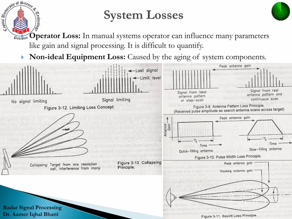
Operator Loss: In manual systems operator can influence many parameters
like gain and signal processing. It is difficult to quantify.
Non-ideal Equipment Loss: Caused by the aging of system components.
4
Radar Signal Processing
Dr. Aamer Iqbal Bhatti
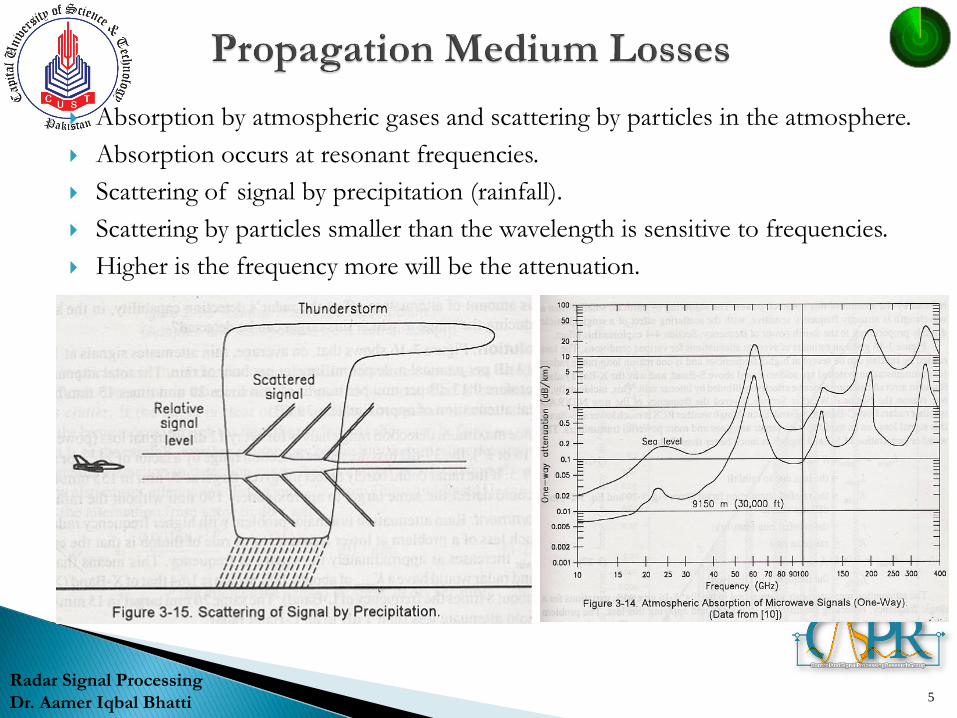
Absorption by atmospheric gases and scattering by particles in the atmosphere.
Absorption occurs at resonant frequencies.
Scattering of signal by precipitation (rainfall).
Scattering by particles smaller than the wavelength is sensitive to frequencies.
Higher is the frequency more will be the attenuation.
5
Radar Signal Processing
Dr. Aamer Iqbal Bhatti
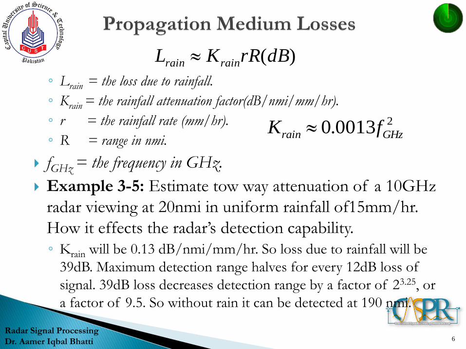
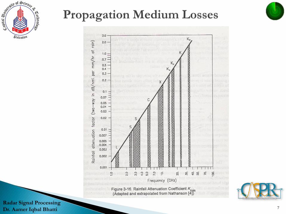
◦ Lrain = the loss due to rainfall.
◦ Krain = the rainfall attenuation factor(dB/nmi/mm/hr).
◦ r = the rainfall rate (mm/hr).
◦ R = range in nmi.
fGHz = the frequency in GHz.
Example 3-5: Estimate tow way attenuation of a 10GHz
radar viewing at 20nmi in uniform rainfall of15mm/hr.
How it effects the radar’s detection capability.
◦ Krain will be 0.13 dB/nmi/mm/hr. So loss due to rainfall will be
39dB. Maximum detection range halves for every 12dB loss of
signal. 39dB loss decreases detection range by a factor of 23.25, or
a factor of 9.5. So without rain it can be detected at 190 nmi.
6
Radar Signal Processing
Dr. Aamer Iqbal Bhatti
)(dBrRKL rainrain
20013.0 GHzrain fK
7
Radar Signal Processing
Dr. Aamer Iqbal Bhatti
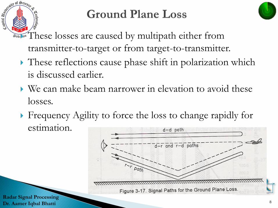
These losses are caused by multipath either from
transmitter-to-target or from target-to-transmitter.
These reflections cause phase shift in polarization which
is discussed earlier.
We can make beam narrower in elevation to avoid these
losses.
Frequency Agility to force the loss to change rapidly for
estimation.
8
Radar Signal Processing
Dr. Aamer Iqbal Bhatti
Signal Processing has an effect of increasing signal to
interference ratio.
Its effectiveness is measured by Process gain.
Signal integration is one method of achieving process gain.
It is the summation of signal contents of several samples of
same range bin in order to increase the signal to interference
ratio.
The effective integration number is given by:
Neff = NL/Li
Li is the integration loss.
9
Radar Signal Processing
Dr. Aamer Iqbal Bhatti
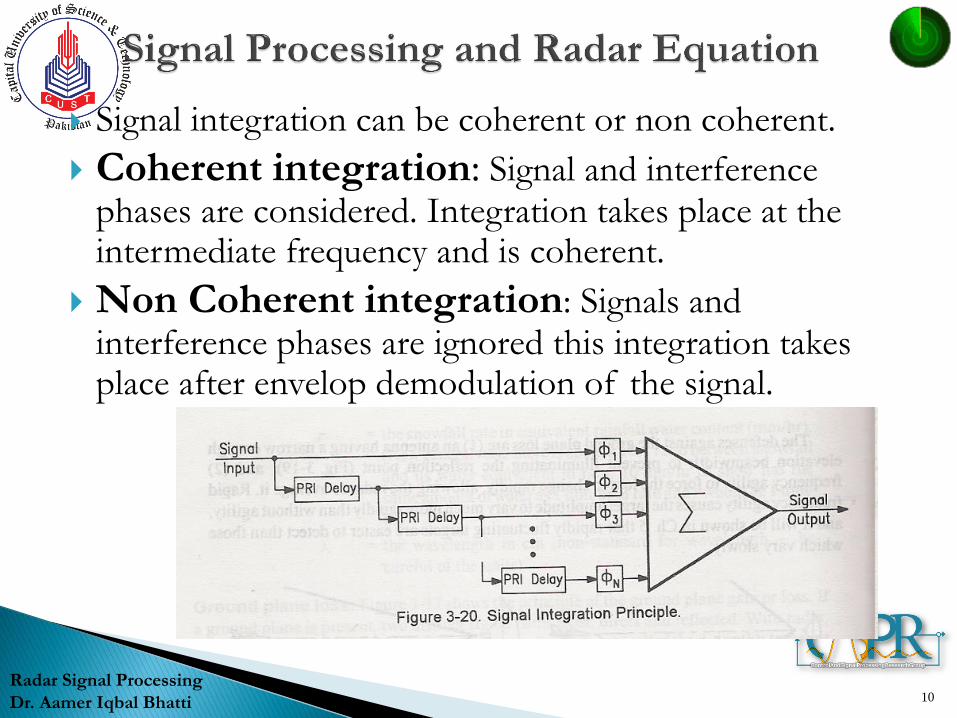
Signal integration can be coherent or non coherent.
Coherent integration: Signal and interference phases are considered. Integration takes place at the intermediate frequency and is coherent.
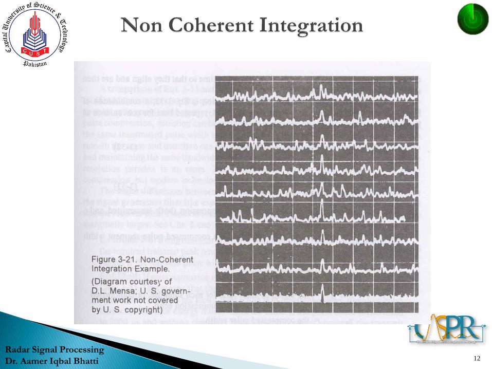
Non Coherent integration: Signals and interference phases are ignored this integration takes place after envelop demodulation of the signal.
10
Radar Signal Processing
Dr. Aamer Iqbal Bhatti
More effective than non coherent
Loss usually ranges from 1.0 to 1.7 and is rarely larger than 2.0, whereas in non coherent the loss can be as large as square root of the integration number for very large integrations.
Coherent integration can be treated by calculating an equivalent integrated SNR ratio and applying this S/N to single hit process
11
Radar Signal Processing
Dr. Aamer Iqbal Bhatti
12
Radar Signal Processing
Dr. Aamer Iqbal Bhatti
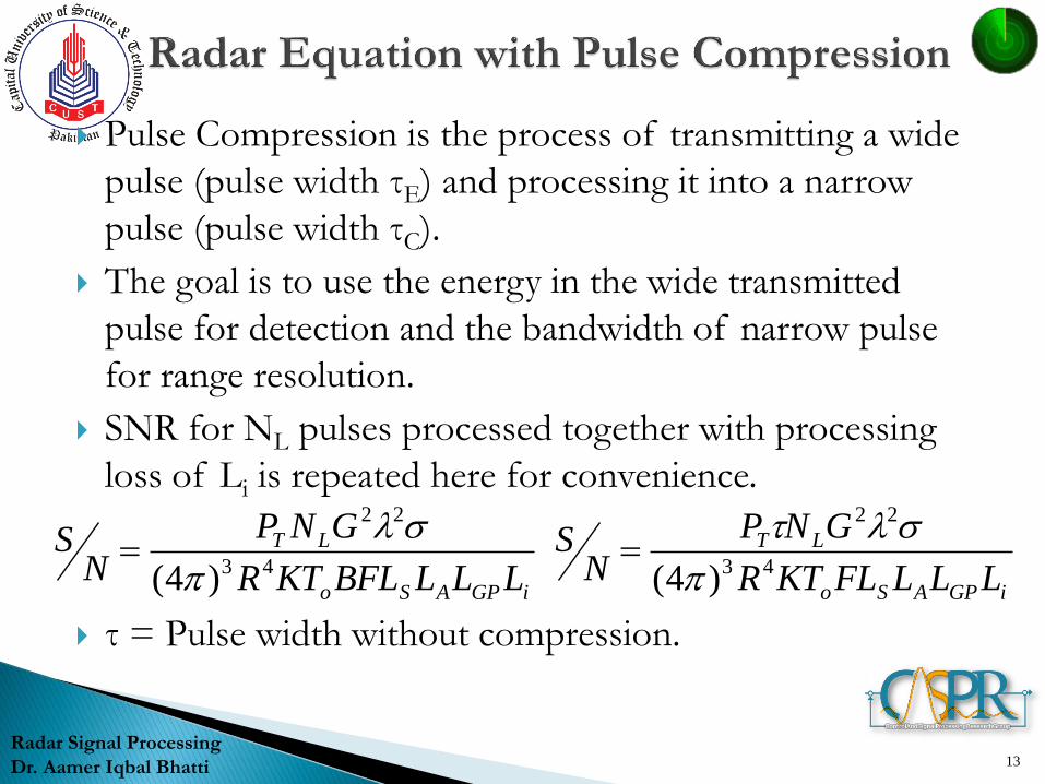
Pulse Compression is the process of transmitting a wide
pulse (pulse width τE) and processing it into a narrow
pulse (pulse width τC).
The goal is to use the energy in the wide transmitted
pulse for detection and the bandwidth of narrow pulse
for range resolution.
SNR for NL pulses processed together with processing
loss of Li is repeated here for convenience.
τ = Pulse width without compression.
13
Radar Signal Processing
Dr. Aamer Iqbal Bhatti
iGPASo
LT
LLLBFLKTR
GNP
NS
43
22
)4(
iGPASo
LT
LLLFLKTR
GNP
NS
43
22
)4(
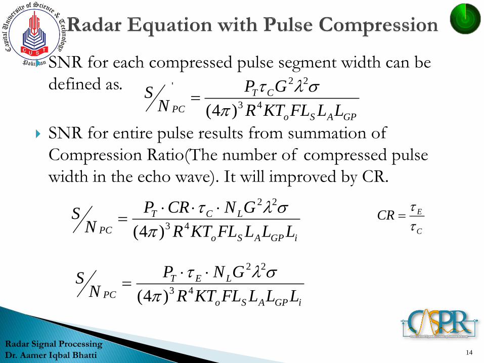
SNR for each compressed pulse segment width can be
defined as.
SNR for entire pulse results from summation of
Compression Ratio(The number of compressed pulse
width in the echo wave). It will improved by CR.
14
Radar Signal Processing
Dr. Aamer Iqbal Bhatti
GPASo
CT
PC LLFLKTR
GP
NS
43
22'
)4(
iGPASo
LCT
PC LLLFLKTR
GNCRP
NS
43
22
)4(
C
ECR
iGPASo
LET
PC LLLFLKTR
GNP
NS
43
22
)4(
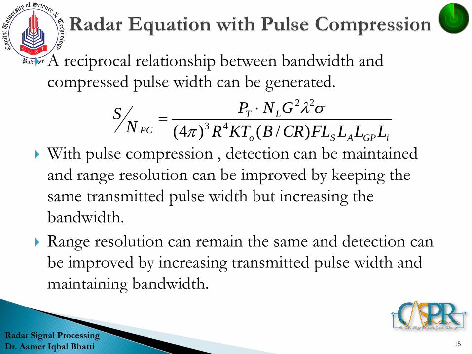
A reciprocal relationship between bandwidth and
compressed pulse width can be generated.
With pulse compression , detection can be maintained
and range resolution can be improved by keeping the
same transmitted pulse width but increasing the
bandwidth.
Range resolution can remain the same and detection can
be improved by increasing transmitted pulse width and
maintaining bandwidth.
15
Radar Signal Processing
Dr. Aamer Iqbal Bhatti
iGPASo
LT
PC LLLFLCRBKTR
GNP
NS
)/()4( 43
22
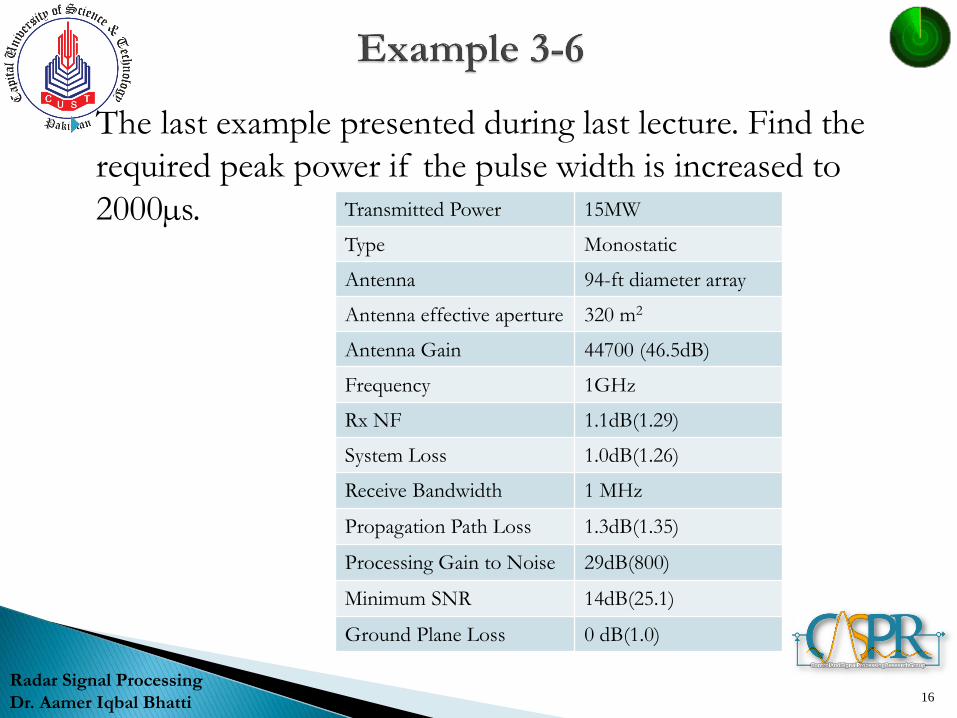
The last example presented during last lecture. Find the
required peak power if the pulse width is increased to
2000µs.
16
Radar Signal Processing
Dr. Aamer Iqbal Bhatti
Transmitted Power 15MW
Type Monostatic
Antenna 94-ft diameter array
Antenna effective aperture 320 m2
Antenna Gain 44700 (46.5dB)
Frequency 1GHz
Rx NF 1.1dB(1.29)
System Loss 1.0dB(1.26)
Receive Bandwidth 1 MHz
Propagation Path Loss 1.3dB(1.35)
Processing Gain to Noise 29dB(800)
Minimum SNR 14dB(25.1)
Ground Plane Loss 0 dB(1.0)
Transmitted pulse width was 1µs with peak power of
1MW. New pulse width is 2000µs, so transmit peak power
will be reduced by a factor of 2000. Which is 7.5kW.
17
Radar Signal Processing
Dr. Aamer Iqbal Bhatti
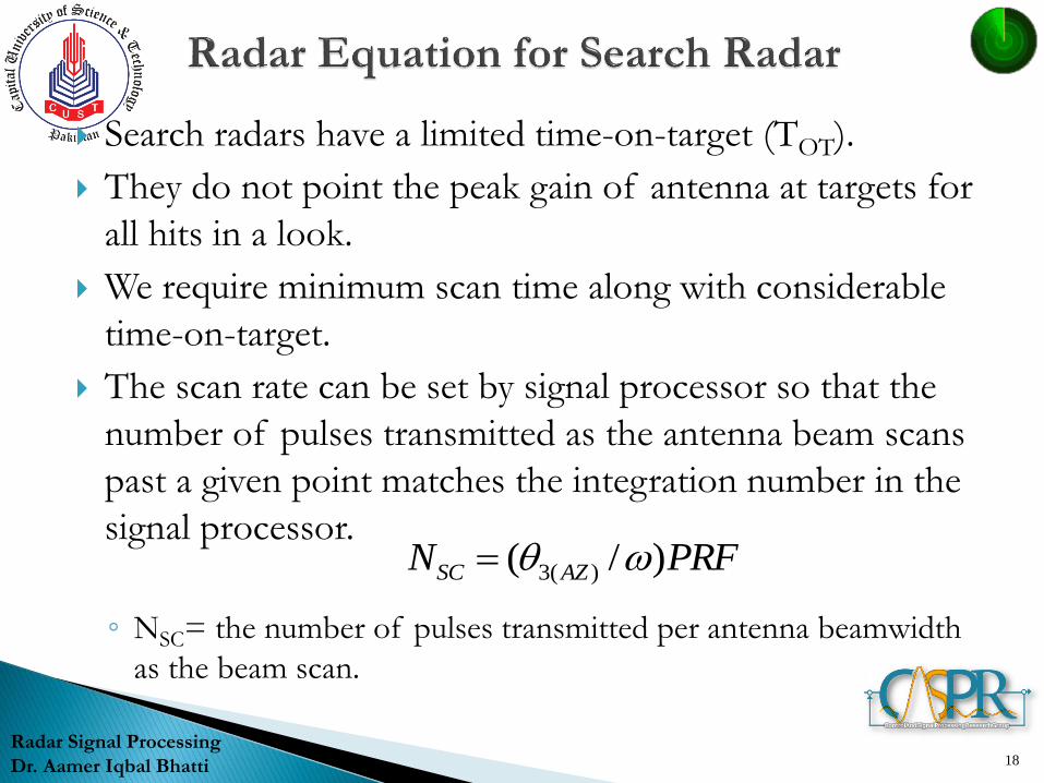
Search radars have a limited time-on-target (TOT).
They do not point the peak gain of antenna at targets for
all hits in a look.
We require minimum scan time along with considerable
time-on-target.
The scan rate can be set by signal processor so that the
number of pulses transmitted as the antenna beam scans
past a given point matches the integration number in the
signal processor.
◦ NSC= the number of pulses transmitted per antenna beamwidth
as the beam scan.
18
Radar Signal Processing
Dr. Aamer Iqbal Bhatti
PRFN AZSC )/( )(3
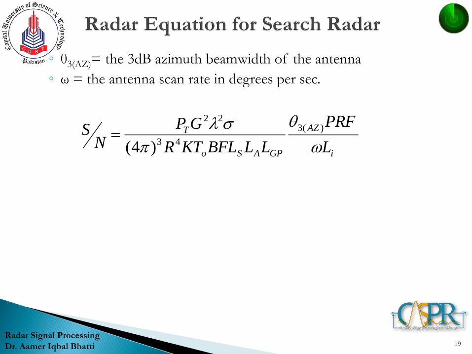
◦ θ3(AZ)= the 3dB azimuth beamwidth of the antenna
◦ ω = the antenna scan rate in degrees per sec.
19
Radar Signal Processing
Dr. Aamer Iqbal Bhatti
i
AZ
GPASo
T
L
PRF
LLBFLKTR
GP
NS
)(3
43
22
)4(