Rack & Pinion Style/Size: 30, 50, 63, 80, 100Rotary Actuator Series CRA1 Rack & Pinion Style/Size:...
52
-X10 -X11 -X16 -X6 -X7 90° 100° 180° 190° S W X Y Z 11- 20- F L S X Y Z T J K 30 50 63 80 100 50 63 80 100 P.192 P.220 to to to P.195 P.197 P.222 P.242 Rotary Actuator Rack & Pinion Style/Size: 30, 50, 63, 80, 100 Series CRA1 Models with cushion or with solenoid valve available. (Only sizes 50 or larger are available.) Angle adjustment is possible. Size 30···············Fine angle adjuster is standard equipment. Size 50 or larger···Angle adjustable type Auto switch is mountable. Adjustment of switch location is easy with rail mounting. Series Variations Fluid Size Standard Made to Order Rotating angle Shaft type Cushion Variations Mounting bracket Shaft type Operating temp. Pattern Both sides angle adjustable One side angle adjustable, One side with cushion Fluororubber seal Option Single shaft Double shaft Single shaft with four chamfers Double shaft key Double shaft with four chamfers None Air cushion With auto switch Angle adjustable type With solenoid valve Clean series Copper-free and fluorine-free (Standard) With One-touch fittings Flange Foot Shaft, Bolt, Parallel key stainless steel spec. Heat resistance 100°C Shaft end form End of rotation Port location Single shaft Single shaft with four chamfers Double shaft key Double shaft with four chamfers Single round shaft Double shaft (Round, With four chamfers) Double round shaft Air Hydraulic oil Page 191 CRB2 CRBU2 CRB1 MSU CRJ CRA1 CRQ2 MSQ MSZ MRQ CRQ2X MSQX D- Courtesy of Steven Engineering, Inc.-230 Ryan Way, South San Francisco, CA 94080-6370-Main Office: (650) 588-9200-Outside Local Area: (800) 258-9200-www.stevenengineering.com
Transcript of Rack & Pinion Style/Size: 30, 50, 63, 80, 100Rotary Actuator Series CRA1 Rack & Pinion Style/Size:...

-X10-X11
-X16
-X6
-X7
90°100°180°190°
SWXYZ
11-20-
F
L
SXYZTJK
30 50 63 80 100 50 63 80 100
P.192
P.220 to
to
to
P.195
P.197
P.222
P.242
Rotary Actuator
Rack & Pinion Style/Size: 30, 50, 63, 80, 100Series CRA1
Models with cushion or with solenoid valve available.(Only sizes 50 or larger are available.)
Angle adjustment is possible.Size 30···············Fine angle adjuster is
standard equipment.Size 50 or larger···Angle adjustable type
Auto switch is mountable.Adjustment of switch location is easy with rail mounting.
Series VariationsFluid
Size
Sta
nd
ard
Mad
e to
Ord
er
Rotating angle
Shaft type
Cushion
Variations
Mounting bracket
Shaft type
Operating temp.
Pattern
Both sides angle adjustableOne side angle adjustable, One side with cushion
Fluororubber seal
Option
Single shaftDouble shaftSingle shaft with four chamfersDouble shaft keyDouble shaft with four chamfers
NoneAir cushion
With auto switch Angle adjustable typeWith solenoid valveClean seriesCopper-free and fluorine-free (Standard) With One-touch fittingsFlange
Foot
Shaft, Bolt, Parallel key stainless steel spec.
Heat resistance 100°C
Shaft end formEnd of rotationPort location
Single shaftSingle shaft with four chamfersDouble shaft keyDouble shaft with four chamfersSingle round shaftDouble shaft (Round, With four chamfers)Double round shaft
Air Hydraulic oil Page
191
CRB2
CRBU2
CRB1
MSU
CRJ
CRA1
CRQ2
MSQ
MSZ
MRQ
CRQ2XMSQX
D-�
P0179-P0242-E.qxd 08.9.29 1:36 PM Page 191
Courtesy of Steven Engineering, Inc.-230 Ryan Way, South San Francisco, CA 94080-6370-Main Office: (650) 588-9200-Outside Local Area: (800) 258-9200-www.stevenengineering.com

CRA1 B 30 90
CRA1 B S
W
50 90
BL 90
180
BL ∗F
NilH
NilP
50 63 80100
90°180°100°190°
90180100190
NilC
Foot bracket : 2 pcs.
Mounting thread: 4 pcs.
Collar ∗ : 4 pcs.
Description
M5 x 0.8 x 25
M8 x 1.25 x 35
M10 x 1.5 x 40
M12 x 1.75 x 50
M12 x 1.75 x 50
∗ Size 30 does not include collars.
Rod end shapeDouble shaft
∗
NilXF ∗XN ∗
RcG
NPT
How to Order
Size
30
50
63
80
100
Foot bracket
CRA1L30-Y-1
CRA1L50-Y-1
CRA1L63-Y-1
CRA1L80-Y-1
CRA1L100-Y-1
Foot Bracket Part No.
Mounting style
Basic styleFoot style
Mounting style Basic styleFoot style
Flange style
90°180°
Rotating angle
Shaft typeSW
X
Y
Z
Standard
Option
Single shaftDouble shaft
Single shaft with four chamfers
Double shaft keyDouble shaft with
four chamfers
PneumaticAir-hydro
StandardCombination of Simple specials/Made to Order
Type
PatternSize
Standard
Option
Rotating angle
Air cushionNone
With air cushion
Size 30
Size 50 to 100
∗ For part numbers, refer to the tables below. ∗ These cannot be combined
with Made to Order.∗ Except the air-hydro type.∗ Except size 30.
∗ Refer to page 196 for the rod-end shape variations.
∗ For pneumatic type only.
∗ Refer to pages 222 to 242 for details.
Refer to pages 195 and 197 for the rod-end shape variations.
Made to Order or port typeRefer to page 194 for Made to Order.
Mounting screws included in foot bracket
192
Rotary Actuator
Series CRA1Rack & Pinion Style/Size: 30, 50, 63, 80, 100
P0179-P0242-E.qxd 08.9.29 1:36 PM Page 192
Courtesy of Steven Engineering, Inc.-230 Ryan Way, South San Francisco, CA 94080-6370-Main Office: (650) 588-9200-Outside Local Area: (800) 258-9200-www.stevenengineering.com

C B W 30
C
D
D
RA1
RA1 B S 50 90
90 J79W
J59W
BL
Mounting style
Built-in magnet
90180100190
90°180°100°190°
∗ Refer to pages 222 to 242 for details.
Nil
P
Grommet
No
No
No
Grommet
Grommet
Connector
Connector
Connector
Grommet
Grommet
DC AC
5V
5V, 12V
12V
5V, 12V
12V
12V
5V, 12V
24V
24V
24V
A76H IC circuit
IC circuit
IC circuit
IC circuit
IC circuit
IC circuit
IC circuit
200V
100V
100 V or less
100V, 200V
200 V or less
100V, 200V
12V
12V
A72
A73
A80
A73C
A80C
A79W
F7NV
F7PV
F7BV
J79C
F7NWV
F7BWV
F7BAV ∗∗
A72H
A73H
A80H
F79
F7P
J79
F79W
F7PW
J79W
F79FA56
A53
A54
A64
A67
A59W
F59
F5P
J59
J51
F59W
F5PW
J59W
F59F
PLC
F7BA ∗∗ F5BA ∗∗
RcG
NPT
How to Order
90180
BL ∗F
∗ For pneumatic type only.NilH
50 63 80100
NilC ∗
NilXF ∗XN ∗
Mounting style
Basic styleFoot style
Basic styleFoot style
Flange style
90°180°
Rotating angle
Shaft typeSW
X
Y
Z
StandardStandard
Option Option
Single shaftDouble shaft
Single shaft with four chamfers
Double shaft keyDouble shaft with
four chamfers
PneumaticAir-hydro
Type
Size
Air cushionNone
With air cushion
Size 30
Size 50 to 100
∗ For part numbers of foot bracket, refer to page 192.
Rotating angle
Number of auto switches
Auto switch
SNil
1 pc.2 pcs.
Note) Maximum number of auto switches mountable is two.
∗ For the applicable auto switch model, refer to the table below.
Type
Ree
d s
wit
chS
olid
sta
te s
wit
ch
Special function
Diagnosis indication (2-color)
Water resistant (2-color)
Diagnosis output (2-color)
Electrical entry
Pre-wiredconnector
Yes
Yes
Yes
Yes
Yes
Indi
cato
r lig
ht
Wiring(Output)
3-wire (NPN equiv.)
2-wire
2-wire
2-wire
3-wire (NPN)
3-wire (PNP)
3-wire (NPN)
3-wire (PNP)
4-wire (NPN)
Load voltage Auto switch model
Size 30 Size 50 to 100
In-linePerpendicular In-line0.5(Nil)
3 (L)
5 (Z)
None(N)
Lead wire ∗length (m)
Applicable load
Relay,PLC
Relay,PLC
Relay, PLC
∗∗ Although it is possible to mount water resistant type auto switches, note that the rotary actuator itself is not of water resistant construction. ∗ Lead wire length symbols:
• Refer to page 199 for applicable switches other than those indicated above.∗ Auto switches are shipped together, (but not assembled).
∗ Auto switches marked with “�” are made to order specifications.
Applicable Auto Switch/Refer to pages 761 to 809 for further information on auto switches.
Refer to pages 796 and 797 for detailed solid state auto switches with pre-wired connectors.
0.5 m ······ Nil (Example) A73C 3 m ······ L (Example) A73CL 5 m ······ Z (Example) A73CZ None ······ N (Example) A73CN
Diagnosis indication (2-color)
���������������������
��������
������������
�
�
����
�
�
�
Rod end shapeDouble shaftRefer to pages 195 and 197 for the rod-end shape variations.
∗ Refer to page 196 for the rod-end shape variations.
StandardCombination of Simple specials/Made to Order
Pattern
∗ These cannot be combined with Made to Order.
∗ Except the air-hydro type.
∗ Except size 30.
Made to Orderor port typeRefer to page 194 for Made to Order.
193
Rotary Actuator with Auto Switch
Series CDRA1Rack & Pinion Style/Size: 30, 50, 63, 80, 100
CRB2
CRBU2
CRB1
MSU
CRJ
CRA1
CRQ2
MSQ
MSZ
MRQ
CRQ2XMSQX
D-�
299-CRA1.qxd 10.10.7 4:37 PM Page 1
Courtesy of Steven Engineering, Inc.-230 Ryan Way, South San Francisco, CA 94080-6370-Main Office: (650) 588-9200-Outside Local Area: (800) 258-9200-www.stevenengineering.com

JIS Symbol
Made to Order(Refer to pages 222 to 242 for details.)
Symbol Specifications/Description Applicable shaft type
—XA1 to XA24XA33 to XA59
XC7XC8 to XC11
XC30
XC31 to XC36
XC37 to XC46
XC47 to XC58
XC59 to XC61XC63, XC64
X6X7 ∗
X10X11X16
S,X,Y,Z,T,J,KS,W,YX,Z,T,J,KS,W,X,T,JS,W,YS,W,X,Y,Z,T,J,K
S,W,Y
S,W,Y
S,W,Y
S,W,X,Y,Z,T,J,KS,W,X,Y,Z,T,J,KS,W,X,Y,Z,T,J,KS,W,X,Y,Z,T,J,KS,W,X,Y,Z,T,J,KS,W,X,Y,Z,T,J,KS,W,X,Y,Z,T,J,K
∗ X7: Not available for the built-in magnet type.
Series CRA1
194
Specifications
Allowable Kinetic Energy/Safe Range of Rotation Time
Mass/Standard
Type
Fluid
Max. operating pressure
Min. operating pressure
Cushion
Allowable surge pressure
Backlash
Ambient and fluid temperature
Tolerance in rotating angle
Pneumatic Air-hydro
63
Air (Non-lube)
1.0 MPa
0.1 MPa
0 to 60°C (No freezing)
80 100 50 63
Hydraulic oil
+ 4° 0
1.5 MPa
Within 1°
—
—
80 1005030
(1)
None
1.9 9.3 17 32 74 9.3 17 32 74
NoneNot attached, Air cushion
(2)
Model
Allowable kinetic energy
Allowable kinetic energy (J)Cushion angle
Adjustable range ofrotation time safe
in operation
Rotation time (s/90°)
0.2 to 1
0.2 to 2
0.2 to 3
0.2 to 4
0.2 to 5
Without cushion
0.01
0.05
0.12
0.16
0.54
With cushion
—
0.98
1.50
2.00
2.90
—
35°
35°
35°
35°
CRA1�W 30
CRA1�� 50
CRA1�� 63
CRA1�� 80
CRA1��100
Note)
Note) Allowable kinetic energy of the bumpers equipped model The maximum absorbed energy under proper adjustment of the cushion needle.
Model
CRA1BW 30
CRA1BW 50
CRA1BW 63
CRA1BW 80
CRA1BW100
90°
0.3
1.5
2.5
4.3
8.5
180°
0.4
1.7
3
5
9.5
Foot bracket
0.1
0.3
0.5
0.9
1.2
Flange bracket
—
0.5
0.9
1.5
2
Standard mass Additional mass
(kg)
Mass/With Auto Switches and Solenoid Valves
Size
30
50
63
80
100
Additional mass
With 2 auto switches
0.1
0.2
0.4
0.6
0.9
With solenoid valve ∗
—
(kg)
Output (N·m)
∗ Mass of the solenoid valve is not included. Refer to page 209 concerning weight of the solenoid valve.
Note 1) Output under the operating pressure of 0.5 MPa. Refer to page 40 for further information.
Note 2) Since CRA1�30 has a stopper installed, there is no backlash produced under pressure.
Size
0.2
0.2
0.2
0.2
Shaft type variations
Shaft pattern sequencing I
Shaft pattern sequencing II
Reversed shaft
Change of rotation range
Fluorine grease
Change of rotation range and
rotation direction of shaft
Change of rotation range and
angle adjusting direction
Change of rotation range and
angle adjusting direction
(Angle adjusting screw is equipped on the left.)
Change of port direction
One side air-hydro, One side air
Stainless steel specifications for main parts
Heat resistant type (100°C)
Both sides angle adjustable type
One side angle adjustable, One side cushion
Fluororubber seal
P0179-P0242-E.qxd 08.9.29 1:36 PM Page 194
Courtesy of Steven Engineering, Inc.-230 Ryan Way, South San Francisco, CA 94080-6370-Main Office: (650) 588-9200-Outside Local Area: (800) 258-9200-www.stevenengineering.com

Series CRA1Rotary ActuatorRack & Pinion Style
195
Clean Series
Copper-free and Fluorine-free Rotary Actuator
With One-touch Fittings
Piping steps and installation space are saved by One-touch fittingsbuilt in the connection ports.
Vacuum ports are equipped to prevent dust from being produced from the rod part of the rotary actuators.
No influence on cathode ray tubes by copper ion and fluorine resin. As standard models are already made applicable to copper-free and fluorine-free styles, they can be applied as they are.
CRA1 Mounting Shaft type Size Rotatingangle Suffix symbolF
With One-touch fittings
Specifications
Applicable Tubing Specifications
Applicable size
Max. operating pressure
Min. operating pressure
Auto switch
Size
Applicable tubing O.D.
Applicable tubing material
30 50
Nylon, Soft nylon, Polyurethane
63
ø4 ø6
30, 50, 63
Pneumatic
Mountable
Refer to pages 202, 204 and 206 for the dimensions.
CRA1 Mounting Size11
Clean Series
Shaft type Suffix symbol
Specifications Applicable size
Max. operating pressure
Min. operating pressure
Auto switch
30, 50
Pneumatic
Mountable
For further specifications, refer to “Pneumatic Clean Series” catalog.
Specifications Applicable size
Max. operating pressure
Min. operating pressure
Auto switch
30, 50, 63, 80, 100
Pneumatic
Mountable
C RA1 Mounting Shaft type Rotating angle30
Shaft typeT
J
K
Single round shaft
Double round shaft
SpecificationsSize
Type
Shaft type
Cushion
Auto switch
30
PneumaticSingle round shaft (T), Double round shaft (K), Double shaft/(Long shaft without key and with
four chamfers) (J)
None
Mountable
Mounting Basic style, Foot style
∗ Refer to page 194 for other specifications.
DimensionsT (Single round shaft)Shaft type
Con
figur
atio
n
K (Double round shaft)J (Double shaft/Long shaft without key and with four chamfers)
(mm)
Double shaft (Long shaft without key and with four chamfers)
Shaft Type Variations/Without Key Grooves (Size 30) Shaft Type: T, J, K
Type
Rotatingangle
Type
Type
1.0 MPa
0.1 MPa
1.0 MPa
0.1 MPa
1.0 MPa
0.1 MPa
Refer to “How to Order” on pages 192 and 193.
CRB2
CRBU2
CRB1
MSU
CRJ
CRA1
CRQ2
MSQ
MSZ
MRQ
CRQ2XMSQX
D-�
P0179-P0242-E.qxd 08.9.29 1:36 PM Page 195
Courtesy of Steven Engineering, Inc.-230 Ryan Way, South San Francisco, CA 94080-6370-Main Office: (650) 588-9200-Outside Local Area: (800) 258-9200-www.stevenengineering.com

Series CRA1
196
Shaft type Size Rotating angle
Shaft typeT
J
K
Single round shaft
Double round shaft
Air cushionNilC
NoneWith air cushion
Mountable
Specifications
Pneumatic Air-hydro50, 63, 80, 100
Air (Non-lube) Hydraulic oil
Not attached, Air cushion None
Note) Except flange style.∗ Refer to page 194 for other specifications.
∗ Refer to pages 204 and 206 for other specifications.
Dimensions (mm)
Shaft type
Configuration
Size506380
100
T (Single round shaft)
D (g6)15172025
H36415060
J (Double shaft/Long shaft without key & with four chamfers)
D (g6)15172025
H36415060
M20222530
N15172025
UU118139167202
K (Double round shaft)
D (g6)15172025
H36415060
UU134158192232
Mounting SizeTypeFluid
Shaft type
Cushion
MountingAuto switch
Basic style, Foot style
Double shaft (Long shaft without key and with our chamfers)
Refer to “How to Order” on pages 192, 193, 208 and 214.
Shaft Variations/Without Keyway (Size 50 to 100)
C RA1
Shaft Type: T, J, K
Single round shaft (T), Double round shaft (K), Double shaft/Long shaft without key and with
four chamfers (J)
P0179-P0242-E.qxd 08.9.29 1:36 PM Page 196
Courtesy of Steven Engineering, Inc.-230 Ryan Way, South San Francisco, CA 94080-6370-Main Office: (650) 588-9200-Outside Local Area: (800) 258-9200-www.stevenengineering.com

S (Single shaft key)
X (Single shaft with four chamfers) Y (Double shaft key) Z (Double shaft with four chamfers)
ø7.8
0
–0.2
�6 0 –0.2
ø7.8
0
–0.2
�6 0 –0.2
ø7.8
0
–0.2
�6 0 –0.2
Series CRA1Rotary ActuatorRack & Pinion Style
197
Shaft type 30 Rotating angle
Refer to “How to Order” on pages 192 and 193.
Single shaft key
Double shaft key
Shaft typeS
X
Y
Z
Max. operating pressure (MPa)
Min. operating pressure (MPa)
Shaft type
Mounting
Auto switch
Specifications30
Pneumatic
1.0 MPa
0.1 MPa
Single shaft key (S), Single shaft with four chamfers (X),
Double shaft key (Y), Double shaft with four chamfers (Z)
Basic style, Foot style
Mountable
∗ Refer to page 194 for other specifications.
Mounting
Single shaft with four chamfers
Double shaft with four chamfers
C RA1
Shaft Variations (Size 30) Shaft Type: S, X, Y, Z
Size
Type
CRB2
CRBU2
CRB1
MSU
CRJ
CRA1
CRQ2
MSQ
MSZ
MRQ
CRQ2XMSQX
D-�
P0179-P0242-E.qxd 08.9.29 1:36 PM Page 197
Courtesy of Steven Engineering, Inc.-230 Ryan Way, South San Francisco, CA 94080-6370-Main Office: (650) 588-9200-Outside Local Area: (800) 258-9200-www.stevenengineering.com

Size: 30 Size: 50 to 100
· Stopper screw A: For end adjustment in clockwise direction· Stopper screw B: For end adjustment in counter clockwise direction
How to Use the Air-hydro Type
Selection
Lubrication
Warning
Caution
Caution
Caution
Warning
Caution
Caution on Design
1. Do not use a rotary actuator of the air-hydro type near flames, or in equipment or machinery that exceeds an ambient temperatures of 60°C.There is a danger of causing a fire because the rotary actuator of the air-hydro type uses a flammable hydraulic fluid.
1. Select the rotary actuator of the air-hydro type based on the combination with the air-hydro unit.Select a proper air-hydro unit that is necessary for good operation of the rotary actuator of the air-hydro type.
1. Make sure to completely discharge the compressed air in the system before filling the air-hydro unit with hydraulic oil.When supplying hydraulic fluid to the air-hydro unit, first confirm that safety measures are implemented to prevent dropping of objects and the release of clamped objects, etc. Then, shut off the air supply and the equipment’s electric power and exhaust the compressed air in the system.If the air-hydro unit’s supply port is opened with compressed air still remaining in the system, there is a danger of hydraulic fluid being blown out.
1. Bleed air from the rotary actuator of the air-hydro type on a regular basis.Since air may accumulate inside a rotary actuator of the air-hydro type, bleed air from it, for example before starting work. Bleed air from a bleeder valve provided on the rotary actuator of the air-hydro type or the piping.
2. Verify the oil level of the air-hydro system on a regular basis.Since a very small amount of hydraulic fluid is discharged from the rotary actuator of the air-hydro type and air-hydro unit circuit, the fluid will gradually decrease. Therefore, check the fluid regularly and refill as necessary.The oil level can be checked with a level gauge in the air-hydro converter.
Maintenance
1. Use self-align fittings in conjunction with the piping for the rotary actuator of the air-hydro type.Do not use a one-touch fitting with the piping for the rotary actuator of the air-hydro type, as this may result in oil leakage.
2. For rotary actuator of the air-hydro type piping, use hard nylon tubing or copper piping.As in the case of hydraulic circuits, surge pressures greater than the operating pressure may occur in a rotary actuator of the air-hydro type’s piping, making it necessary to use safer piping materials.
Piping
1. Do not use in an environment, equipment, or machine that is not compatible with oil mist.Rotary actuators of the air-hydro types generate an oil mist during operation which may affect the environment.
2. Be sure to install an exhaust cleaner on the directional control valve for the rotary actuator of the air-hydro type.A very small amount of hydraulic fluid is discharged from the exhaust port of the rotary actuator of the air-hydro type’s directional control valve, which may contaminate the surrounding area.
3. Install a rotary actuator of the air-hydro type in locations where it can be serviced easily.Since the rotary actuator of the air-hydro type requires maintenance, such as refilling of hydraulic fluid and bleeding of air, ensure sufficient space for these activities.
4. Do not use in cases where external leakage of hydraulic oil may adversely affect equipment or machinery.Although it only occurs in minute
amounts, a certain amount of sliding leakage from the piston seal is unavoidable with the rotary actuator of the air-hydro type. Because of the construction of the rotary actuator of the air-hydro type, hydraulic oil may leak into the outside due to sliding leakage.
198
Series CRA1
Refer to the model selecting order step for rotary actuators on page 37 concerning allowable loads on the shafts of Series CRA1.
Angle
adju
stmen
t ran
ge ±3
°
Direction indicating label
Key
Angle
adju
stmen
t ran
ge ±3
°
Angle
adju
stmen
t ran
ge ±3
°
A port
Stopper screw B
Stopper screw A
B port
Rotation range ofke
yway
90°
Rotation range of key
way
180°
Angle adjustment range ±3°
Direction indicating label
Key
A port B port
Rotation range ofke
yway
90°+4
° 0 +4
° 0
Rotation range of keyway 180°+4°
0
Rotation range of keyway 190°+4° 0
Rotation Range of Keyway
If air pressure is applied from the A port side of the direction indication label, the shaft rotates clockwise. If air pressure is applied from the B port side, the shaft rotates counterclockwise.
Even if the torque that is generated by the rotary actuator is small, the parts could become damaged depending on the inertia of the load. Therefore, the rotation time should be determined by calculating the load’s inertial moment and kinetic energy. Refer to pages 31 and 33 for details on how to set the rotation time.
Allowable load on the shaftHow to Set Rotation Time
Rotation range of keyw
ay10
0°
P0179-P0242-E.qxd 08.9.29 1:36 PM Page 198
Courtesy of Steven Engineering, Inc.-230 Ryan Way, South San Francisco, CA 94080-6370-Main Office: (650) 588-9200-Outside Local Area: (800) 258-9200-www.stevenengineering.com

Part no.
P294010-24
P294020-24
Auto switches in addition to those listed above are also available.
Series CDRA1Rotary Actuator with Auto SwitchRack & Pinion Style
Model Description
Round head Phillips screw: 2 pcs.Hexagon nut: 2 pcs.
CDRA1�W30
CDRA1��50 to 100
199
Rotation Range of Keyway/Auto Switch Mounting Position
Proper Auto Switch Mounting Position at Rotation End
CDRA1��50 to 100
Size: 30CDRA1�W30
Working Principle
In the diagram below, auto switch B is ON. When pressure is applied from A, the piston moves to B, causing the shaft to rotate clockwise. At this time, magnet B goes out of the movement range of auto switch B, causing auto switch B to turn OFF. Furthermore, the piston moves to the right, causing magnet A to enter the movement range of auto switch A. As a result, auto switch A turns ON.
Model A (mm)
9 (19)
9 (26)
11 (30)
15 (37)
27 (60)
Operating angle θ m
95°
65°
60°
45°
35°
Hysteresis angle
CDRA1�W30-90
CDRA1��50-90
CDRA1��63-90
CDRA1��80-90
CDRA1��100-90
∗ The dimensions inside ( ) are for 180°. ∗∗ Up to 2 auto switches can be mounted per actuator. Note) The values given in the table above are representative values.
In the actual setting, adjust the value after confirming the auto switch performance. Please consult with SMC concerning the angles for the auto switches other than the models D-
A73 and D-A53.
Operating angle θ m: Converts the operating range (Lm) of the auto switch into the rotation angle.Angle of hysteresis: The hysteresis of the auto switch is converted to degrees.
Size: 50 to 100CDRA1��50 to 100
CDRA1�W30
Angl
e ad
just
men
t ran
ge ±
3°
Angl
e ad
just
men
t ran
ge ±3
°
Angl
e ad
just
men
t ran
ge ±3
°
Rotation range ofke
yway
90°
Rotation range ofke
yway
180°
Auto switch
Direction indicating label
A port B port
Angle adjustment range ±3°
Key
Direction indicating label
Key
A port B port
Auto switchRotation range of k
eywa
y 90°
Rotation range of keyw
ay10
0°+4
° 0
+4°
0
Rotation range of keyway 180°Rotation range of keyway 190°
+4° 0
+4° 0
Magnet A Magnet B
Auto switch A Auto switch B
Auto switchD-A73
Auto switchD-A53
Most sensitive position
Operating range at propermounting position (Lm/2)
Operating range ofsingle auto switch (Lm)
20°
20°
10°
7°
5°
Note 1) The above part numbers include 2 pieces of mounting screws and 2 pieces of nuts.Note 2) To order a set for 1 unit, the ordering quantity should be “1”.
Sets of Mounting Screws for Auto Switch
Type Model Features Applicable sizeElectrical entry
Grommet (In-line)
Grommet (In-line)With timer
30
50 to 100
D-F7NTL
D-F5NTLSolid state switch
∗ With pre-wire connector is also available for D-F5NTL, D-F7NTL. For details about pre-wire connectors, refer to pages 796 and 797.
Auto Switch Specifications/Refer to page 761 to 809 for further information on auto switch single body.
CRB2
CRBU2
CRB1
MSU
CRJ
CRA1
CRQ2
MSQ
MSZ
MRQ
CRQ2XMSQX
D-�
P0179-P0242-E.qxd 08.9.29 1:36 PM Page 199
Courtesy of Steven Engineering, Inc.-230 Ryan Way, South San Francisco, CA 94080-6370-Main Office: (650) 588-9200-Outside Local Area: (800) 258-9200-www.stevenengineering.com

Series CRA1
200
Construction
Without air cushionSize: 30
Without air cushionSize: 50 to 100
No.
q
w
e
r
t
y
u
i
o
!0
!1
Body
Right cover
Left cover
Piston
Shaft
Rack
Stopper
Stopper screw
Slider
Bearing retainer
Tube gasket
Description Material
Aluminum alloy
Aluminum alloy
Aluminum alloy
Aluminum alloy
Chrome molybdenum steel
Carbon steel
Chrome molybdenum steel
Chrome molybdenum steel
Resin
Zinc alloy Note)
NBR
Note
Anodized
Anodized
Anodized
Chromated
Black dyed
Black painted
No.
!2
!3
!4
!5
!6
!7
!8
!9
@0
@1
@2
@3
Piston seal
O-ring
Bearing
Hexagon socket head cap screw with spring washer
Hexagon socket head cap flange screw
Cross-recessed countersunk head screw
Hexagon nut
Spring pin
Parallel key
Parallel key
Connecting screw
Round head Phillips screw
Description Material
NBR
NBR
Bearing steel
Chrome molybdenum steel
Chrome molybdenum steel
Steel wire
Steel wire
Steel wire
Carbon steel
Carbon steel
Carbon steel
Steel wire
Note
Black zinc chromated
Zinc chromated
Black dyed
Black dyed
Zinc chromated
Black zinc chromated
Component Parts Component Parts
Note) Size 50 to 100: Aluminum alloy (Anodized)
P0179-P0242-E.qxd 08.9.29 1:36 PM Page 200
Courtesy of Steven Engineering, Inc.-230 Ryan Way, South San Francisco, CA 94080-6370-Main Office: (650) 588-9200-Outside Local Area: (800) 258-9200-www.stevenengineering.com
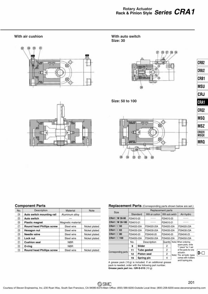
With air cushion With auto switch Size: 30
Size: 50 to 100
Size
P294010-20
P294010-21
P294020-20A
P294030-20A
P294040-20
P294050-20A
P294020-20A
P294030-20A
P294040-20
P294050-20A
P294010-20
P294010-21
P294020-20A
P294030-20A
P294040-20
P294050-20A
P294020-23A
P294030-23A
P294040-23
P294050-23A
Standard
No. Description
Slider
Tube gasket
Piston seal
Spring pin
With air cushion
Replacement parts
With auto switch Air-hydro
Replacement Parts (Corresponding parts shown below are set.)
CRA1�W 30-90
CRA1�W 30-180
CRA1��50
CRA1��63
CRA1��80
CRA1��100
Corresponding parts
9
11
12
19
Quantity
2
2
2
4
Note) When ordering spare parts, write “1 piece” for 1 set of the parts for one actuator.
Note) The air-hydro types comes with 4 sliders and 8 spring pins.
A grease pack (10 g) is included. If an additional grease pack is needed, order with the following part number.Grease pack part no.: GR-S-010 (10 g)
Series CRA1Rotary ActuatorRack & Pinion Style
201
No.
@4
@5
@6
@7
@8
@9
#0
#1
#2
#3
Auto switch mounting rail
Auto switch
Plastic magnet
Round head Phillips screw
Hexagon nut
Needle valve
Lock nut
Cushion seal
O-ring
Round head Phillips screw
Description Material
Aluminum alloy
—
Magnetic material
Steel wire
Steel wire
Steel wire
Steel wire
NBR
NBR
Steel wire
Note
Nickel plated
Nickel plated
Nickel plated
Nickel plated
Nickel plated
Component Parts
CRB2
CRBU2
CRB1
MSU
CRJ
CRA1
CRQ2
MSQ
MSZ
MRQ
CRQ2XMSQX
D-�
P0179-P0242-E.qxd 08.9.29 1:36 PM Page 201
Courtesy of Steven Engineering, Inc.-230 Ryan Way, South San Francisco, CA 94080-6370-Main Office: (650) 588-9200-Outside Local Area: (800) 258-9200-www.stevenengineering.com

Foot style: CRA1LW30
Series CRA1
202
Size 30/Basic Style: CRA1BW, Foot Style: CRA1LW
Basic style: CRA1BW30
This drawing is for 90° specifications.
8 x M5 x 0.8 depth 6(Opposite side 4 locations)
A port B port
Mounting hole
4 x ø6
A port B port
∗ ( ) are the dimensions for rotation of 180°. The dimensions below show pressurization to B port.
2 x M5 x 0.8
P0179-P0242-E.qxd 08.9.29 1:36 PM Page 202
Courtesy of Steven Engineering, Inc.-230 Ryan Way, South San Francisco, CA 94080-6370-Main Office: (650) 588-9200-Outside Local Area: (800) 258-9200-www.stevenengineering.com

Series CDRA1Rotary Actuator with Auto SwitchRack & Pinion Style
4 x ø6
2 x M5 x 0.8
Auto switchD-A73
8 x M5 x 0.8 depth 6(Opposite side 4 locations)
Mounting hole Auto switch
D-A73
A port B port
This drawing is for 90° specifications.
A port B port
(P
erpe
ndic
ular
ele
ctric
al e
ntry
)
203
Size 30/Basic Style: CDRA1BW, Foot Style: CDRA1LWWith auto switchBasic style: CDRA1BW30
Foot style: CDRA1LW30
∗ ( ) are the dimensions for rotation of 180°.The dimensions below show pressurization to B port.
CRB2
CRBU2
CRB1
MSU
CRJ
CRA1
CRQ2
MSQ
MSZ
MRQ
CRQ2XMSQX
D-�
P0179-P0242-E.qxd 08.9.29 1:37 PM Page 203
Courtesy of Steven Engineering, Inc.-230 Ryan Way, South San Francisco, CA 94080-6370-Main Office: (650) 588-9200-Outside Local Area: (800) 258-9200-www.stevenengineering.com

CRA1BS 50
CRA1BS 63
CRA1BS 80
CRA1BS100
A
Rc 1/8
Rc 1/8
Rc 1/4
Rc 3/8
62
76
92
112
B
48
60
72
85
C
46
57
70
85
D(g6)
D(g6)
DD(h9)
15
17
20
25
25
30
35
40
F
2.5
2.5
3
4
H
36
41
50
60
J K
5
5
5
5
S U
98
117
142
172
W
17
19.5
22.5
28
BA
17
20
23.5
25
BB
8.5
10
12
12.5
15
17
20
25
G
11
13
15
19
M
20
22
25
30
N
15
17
20
25
UU
118
139
167
202
L
14
16
19
24
CA
8.5
10
12
12.5
CB
13
14
18
18
∗ In addition to Rc, G and NPT are also available.
144(177)
163(201.5)
186(230)
245(311)
25
30
40
45
lb
5 0-0.030
6 0-0.030
6 0-0.030
8 0-0.036
CRA1BW 50
CRA1BW 63
CRA1BW 80
CRA1BW100
G11131519
H27293844
N15172025
U 89105130156
L14161924
CRA1BX 50CRA1BX 63CRA1BX 80CRA1BX100
H36415060
K5555
UU134158192232
l
25304045
CRA1BY 50CRA1BY 63CRA1BY 80CRA1BY100
H27293844
M20222530
N15172025
UU109127155186
L14161924
CRA1BZ 50CRA1BZ 63CRA1BZ 80CRA1BZ100
G11131519
øD is the shaft dimension.
Series CRA1
Size: 50 to 100Single shaft type: CRA1BS
Single shaft
(Opposite side 4 locations)
2 x Port size
A port B port
Double shaft type: CRA1BW Double shaft
Size 50, 63, 80, 100/Basic Style: CRA1B�
Model Port size ∗
• The dimensions above show pressurization to B port.∗ ( ) are the dimensions for rotation of 180° and 190°.
M8 x 1.25Depth 8
M10 x 1.5Depth 12
M12 x 1.75Depth 13
M12 x 1.75Depth 14
Key dimensions
For model with air cushion
Model
Note) Other dimensions are the same as the single shaft.
Model
Note) Other dimensions are the same as the single shaft.
Single shaft with four chamfers: CRA1BX
Double shaft key: CRA1BY Double shaft with four chamfers: CRA1BZ
Note) Other dimensions are the same as the single shaft.
Note) Other dimensions are the same as the single shaft.
Model Model
204
P0179-P0242-E.qxd 08.9.29 1:37 PM Page 204
Courtesy of Steven Engineering, Inc.-230 Ryan Way, South San Francisco, CA 94080-6370-Main Office: (650) 588-9200-Outside Local Area: (800) 258-9200-www.stevenengineering.com

CDRA1BS 50CDRA1BS 63CDRA1BS 80CDRA1BS100
62 76 92112
RcRcRcRc
48607285
46577085
15172025
25303540
2.52.53 4
36415060
5555
98117142172
17 19.522.528
17 20 23.525
8.510 12 12.5
8.510 12 12.5
13141818
33333333
13.514.515.516
12121212
14212939
34343434
25304045
156 (189)175 (213.5)199 (243)259 (325)
M 8 x 1.25 depth 8M10 x 1.5 depth 12
M12 x 1.75 depth 13M12 x 1.75 depth 14
A B C F H J K S U W BA BB CA CB SA SB SC SD SEDD(h9)
D(g6) lb
18
18
14
38
5 0-0.030
6 0-0.030
6 0-0.030
8 0-0.036
CDRA1BW 50CDRA1BW 63CDRA1BW 80CDRA1BW100
20222530
15172025
118139167202
14161924
15172025
M N UU LD(g6) G
11131519
Series CDRA1Rotary Actuator with Auto SwitchRack & Pinion Style
Size 50, 63, 80, 100/Basic Style: CRA1B�
ModelKey dimensions
Model
Double Shaft Type
Single Shaft TypeThe dimensions below show pressurization to B port.
∗ ( ) are the dimensions for rotation of 180° and 190°.
Single shaft with four chamfers:CDRA1BX�
Double shaft key:CDRA1BY�
Double shaft with four chamfers:CDRA1BZ�
Model H27293844
N15172025
U L14161924
CDRA1BX�50 CDRA1BX�63CDRA1BX�80CDRA1BX�100
Model H36415060
K5555
UU134158192232
l
25304045
CDRA1BY�50CDRA1BY�63CDRA1BY�80CDRA1BY�100
Model H27293844
M20222530
N15172025
U UU109127155186
L14161924
CDRA1BZ�50CDRA1BZ�63CDRA1BZ�80CDRA1BZ�100
G11131519
G11131519
Note) Other dimensions are the same as the single shaft.
Note)Other dimensions are the same as the single shaft.
Note)Other dimensions are the same as the single shaft.
89105130156
89105130156
∗ In addition to Rc, G and NPT are also available.
øD is the shaft dimension.
Port size ∗
205
With auto switchSingle shaft type: CDRA1BS
(Opposite side 4 locations)
Auto switchD-A53
A port
2 x Port sizeB port
Single shaft Double shaft
Double shaft type:CDRA1BW
CRB2
CRBU2
CRB1
MSU
CRJ
CRA1
CRQ2
MSQ
MSZ
MRQ
CRQ2XMSQX
D-�
P0179-P0242-E.qxd 08.9.29 1:37 PM Page 205
Courtesy of Steven Engineering, Inc.-230 Ryan Way, South San Francisco, CA 94080-6370-Main Office: (650) 588-9200-Outside Local Area: (800) 258-9200-www.stevenengineering.com

LA
62
76
92
112
F
4
5
5
5
H
39
45
55
60
114
136
165
190
9
11.5
13.5
13.5
13
15
18
18
90
105
130
150
50
59
76
92
110
130
160
180
81
101
119
133
MM U FD FT FX FY ZX ZY
9
11
13
13
44
55
67
87
41
48
58
73.5
108
127
154
189.5
4.5
5
6
6
200(233)
235(273.5)
274(318)
333(399)
224(257)
263(301.5)
316(360)
375(441)
LB LC LD LE LF LH LTM6 x 1.0 depth 12
M6 x 1.0 depth 12
M8 x 1.25depth 16
M10 x 1.5 depth 20
H39455560
N15172025
U114136165190
UU134158190220
CRA1FW�50CRA1FW�63CRA1FW�80CRA1FW�100
H30334344
N15172025
U105124153174
H39455560
U114136165190
UU150177215250
CRA1FX�50CRA1FX�63CRA1FX�80CRA1FX�100
CRA1FY�50CRA1FY�63CRA1FY�80CRA1FY�100
H30334344
N15172025
U105124153174
UU125146178204
CRA1FZ�50CRA1FZ�63CRA1FZ�80CRA1FZ�100
Note) The dimensions of shaft key and four chamfers are the same as standard.
Series CRA1
Size 50, 63, 80, 100/Foot Style: CRA1L�, Flange Style: CRA1F�
Flange styleDouble shaft: CRA1FW
Flange styleSingle shaft with four chamfers: CRA1FX
Model
CRA1L��50
CRA1L��63
CRA1L��80
CRA1L��100
• Dimensions above show pressurization to B port.∗ ( ) are the dimensions for rotation of 180° and 190°.
Mounting hole
A port B port
Foot bracket
Flange styleDouble shaft key: CRA1FY
Flange styleDouble shaft with four chamfers: CRA1FZ
Model
CRA1F��50
CRA1F��63
CRA1F��80
CRA1F��100
Note) Other dimensions are the same as standard.
Model
Note) Other dimensions are the same as the single shaft.
Note) Other dimensions are the same as the single shaft.
Note) Other dimensions are the same as the single shaft.
Note) Other dimensions are the same as the single shaft.
Model Model Model
206
Foot style: CRA1L� Flange styleSingle shaft: CRA1FS
4 x øLB
2 x MM
4 x øFD
P0179-P0242-E.qxd 08.9.29 1:37 PM Page 206
Courtesy of Steven Engineering, Inc.-230 Ryan Way, South San Francisco, CA 94080-6370-Main Office: (650) 588-9200-Outside Local Area: (800) 258-9200-www.stevenengineering.com

CDRA1L��50
CDRA1L��63
CDRA1L��80
CDRA1L��100
LA
62
76
92
112
LB
9
11
13
13
LC
44
55
67
87
LD212
(245)
247(285.5)
287(331)
347(413)
LE236
(269)
275(313.5)
329(373)
389(455)
LH
108
127
154
189.5
LF
41
48
58
73.5
LT
4.5
5
6
6
CDRA1F��50
CDRA1F��63
CDRA1F��80
CDRA1F��100
F
4
5
5
5
H
39
45
55
60
MMM6 x 1.0depth 12
M6 x 1.0depth 12
M8 x 1.25depth 16
M10 x 1.5depth 20
U
114
136
165
190
FD
9
11.5
13.5
13.5
FT
13
15
18
18
FX
90
105
130
150
FY
50
59
76
92
ZX
110
130
160
180
ZY
81
101
119
133
CDRA1FW�50CDRA1FW�63CDRA1FW�80CDRA1FW�100
H39455560
N15172025
U114136165190
UU134158190220
U105124153174
CDRA1FX�50CDRA1FX�63CDRA1FX�80CDRA1FX�100
H30334344
N15172025
CDRA1FY�50CDRA1FY�63CDRA1FY�80CDRA1FY�100
H39455560
U114136165190
UU150177215250
CDRA1FZ�50CDRA1FZ�63CDRA1FZ�80CDRA1FZ�100
H30334344
N15172025
U105124153174
UU125146178204
With auto switch
Note) The dimensions of shaft key and four chamfers are the same as standard.
Series CDRA1Rotary Actuator with Auto SwitchRack & Pinion Style
Size 50, 63, 80, 100/Foot Style: CDRA1L, Flange Style: CDRA1F
Foot style: CDRA1L�Flange styleSingle shaft: CRA1FS
Foot bracket Mounting holes
Auto switchD-A53
A port B port
Dimensions above show pressurization to B port.∗ ( ) are the dimensions for rotation of 180° and 190°.
ModelModel
Note) Other dimensions are the same as standard.
Model Model Model Model
Note) Other dimensions are the same as the single shaft.
Flange styleDouble shaft:CDRA1FW
Flange styleSingle shaft with four chamfers: CDRA1FX
Flange styleDouble shaft key:CDRA1FY
Flange styleDouble shaft with four chamfers: CDRA1FZ
Note) Other dimensions are the same as the single shaft.
Note) Other dimensions are the same as the single shaft.
Note) Other dimensions are the same as the single shaft.
207
4 x øLB
2 x MM
4 x øFD
CRB2
CRBU2
CRB1
MSU
CRJ
CRA1
CRQ2
MSQ
MSZ
MRQ
CRQ2XMSQX
D-�
P0179-P0242-E.qxd 08.9.29 1:37 PM Page 207
Courtesy of Steven Engineering, Inc.-230 Ryan Way, South San Francisco, CA 94080-6370-Main Office: (650) 588-9200-Outside Local Area: (800) 258-9200-www.stevenengineering.com

CVRA1
CDVRA1
90180100190
B W 50 90 1 1 G
B S 50 90 1 1 G J59W
SNil
GHETDL
LNLOM
MNMO
12345
12345679
50 63 80100B
L ∗
SWXYZ
Made to OrderRefer to page 209 for details.
Nil
P
Standard Combination of Simple specials/Made to Order
Pattern
∗ Lead wire length symbols: 0.5 m ······ Nil (Example) A53 3 m ······ L (Example) A53L 5 m ······ Z (Example) A53Z ∗ Refer to page 199 for applicable switches other than those indicated above. ∗ Auto switches are shipped together, (but not assembled).
∗ Auto switches marked with “�” are made-to-order specifications.
Applicable Auto Switch/Refer to pages 761 to 809 for further information on auto switches.
No
3-wire(NPN equiv.)
2-wire
2-wire
2-wire
3-wire (NPN)
3-wire (PNP)
3-wire (NPN)
3-wire (PNP)
4-wire (NPN)
DC AC
��������������
��������������
��
5V
5V, 12V
5V, 12V
12V
12V
5V, 12V
24V
24V
24V
IC circuit
IC circuit
IC circuit
IC circuit
IC circuit
100V, 200V
200 V or less
100V, 200V
12V
12V
A56
A53
A54
A64
A67
A59W
F59
F5P
J59
J51
F59W
F5PW
J59W
F59F
PLC
Rotary Actuator with Solenoid Valve
Series CVRA1Rack & Pinion Style/Size: 50, 63, 80, 100
How to Order
Rated voltage 100 VAC 50/60 Hz200 VAC 50/60 Hz
110 to 120 VAC, 50/60 Hz220 VAC, 50/60 Hz
24 VDC12 VDC
240 VAC, 50/60 HzOther
Electrical entryGrommet (Lead wire: 300 mm)Grommet (Lead wire: 600 mm)
Grommet terminalConduit terminal
DIN terminal
L plugconnector
M plugconnector
Solenoid valve configurationSingle solenoidDouble solenoidClosed centerExhaust centerPressure center
With lead wireWithout lead wireWithout connector
With lead wireWithout lead wireWithout connector
Light/Surge voltage suppressorNilZ ∗S ∗
Manual overrideNilBC
NoneLocking B typeLocking C type
∗ Light attached type (Z) is not available for grommet type. Surge voltage suppressor attached type is available only for grommet type.
Mounting style Basic styleFoot style
Shaft type Built-in magnet
With solenoid valve
Note) No flange style “F” is available.
∗ Refer to pages 222 to 242 for details.
Without auto switch
Withauto switch
Standard
Option
Single shaftDouble shaft
Single shaft with four chamfersDouble shaft key
Double shaft with four chamfers
TypeNilU
Size Rotating angle
Standard
Option
90°180°100°190°
∗ Except angle adjustable type “U”.
Auto switch ∗ For the applicable auto
switch model, refer to the table below.
StandardAngle adjustable
Nil C ∗
Air cushionNone
With air cushion
Number of auto switches
1 pc.2 pcs.
Note) Maximum number of auto switches mountable is two.
Refer to pages 796 and 797 for detailed solid state auto switches with pre-wired connectors.
Type
Ree
d s
wit
chS
olid
sta
te s
wit
ch
Special function
Diagnosis indication (2-color)
Diagnosis indication (2-color)
Electrical entry
Pre-wiredconnector
Grommet Yes
Yes
Grommet
Indi
cato
r lig
ht
Wiring(Output)
Load voltageAuto switch
model 0.5(Nil)
3 (L)
5 (Z)
Applicable load
Relay,PLC
Relay,PLC
Lead wire length ∗(m)
Diagnosis output (2-color)
Yes Relay,PLC
∗ Refer to page 196 for the rod-end shape variations.
NoneWith light/surge voltage suppressor
With surge voltage suppressor
208
P0179-P0242-E.qxd 08.9.29 1:37 PM Page 208
Courtesy of Steven Engineering, Inc.-230 Ryan Way, South San Francisco, CA 94080-6370-Main Office: (650) 588-9200-Outside Local Area: (800) 258-9200-www.stevenengineering.com

AC
DC
AC
DC
CVRA1��50 to 100 0.2 0.2 0.3 0.4 0.4
(kg)
0.4
Manual Override
Electrical Wiring
How to Adjust the Rotation Speed
Instant Energizing Time
Made to Order(Refer to pages 222 to 242 for details.)
Symbol Specifications/Description Applicable shaft typeShaft type variations
Shaft pattern sequencing I
Shaft pattern sequencing II
Reversed shaft
Change of rotation range
Fluorine grease
Change of rotation range and rotation direction of shaft
Change of rotation range and angle adjusting direction
Change of rotation range and angle adjusting direction(Angle adjusting screw is equipped on the left.)
Stainless steel specifications for main parts
Both sides angle adjustable type
One side angle adjustable, One side cushion
—XA1 to XA24XA33 to XA46
XC7XC8 to XC11
XC30XC31 to XC36XC37 to XC46
XC47 to XC58
X6X10X11
S,X,Y,Z,T,J,K
S,W,Y
X,Z,T,J,K
S,W,X,T,J
S,W,Y
S,W,X,Y,Z,T,J,K
S,W,Y
S,W,Y
S,W,Y
S,W,X,Y,Z,T,J,K
S,W,X,Y,Z,T,J,K
S,W,X,Y,Z,T,J,K
PrecautionsBe sure to read before handling. Refer to front matters 38 and 39 for Safety Instructions and pages 4 to 13 for Rotary Actuator and Auto Switch Precautions.
Series CVRA1Rotary Actuator with Solenoid ValveRack & Pinion Style
Rotation Range of KeywaySolenoid Valve Mounting Positions
Rotation range ofke
yway
90°+4
° 0
Rotation range of key
way
100°
+4°
0
Rotation range of keyw
ay18
0°+4
° 0
Rotation range of ke
yway
190°
+4°
0
Note) Light is not available on grommet type.
Light/Surge Voltage Suppressor
Rat
ed v
olta
ge
Less
than
100
V10
0 V
or
mor
e
AC
DC
AC
DC
Terminal no.1
Terminal no.1 (+)
Terminal no.1 (+)
Terminal no.1
Terminal no.2 (–)
Terminal no.2 (–)
Terminal no.2
Terminal no.2
Coi
lC
oil
Coi
lC
oil
Fluid
Proof pressure
Max. operating pressure
Min. operating pressure
Ambient and fluid temperature
Lubrication
Mounting
Grommet, Grommet terminal, Conduit terminal, DIN terminal, L plug connector, M plug connector
100, 200 V (50/60 Hz)
24 V
–15 to +10% of the rated voltage
Equivalent to B class (130°C)
Inrush 5.6 VA (50 Hz), 5.0 VA (60 Hz)
Holding 3.4 VA (50 Hz), 2.3 VA (60 Hz)
1.8 W
Electrical entry
Allowable voltage change
Coil insulation
Apparent power
Power consumption
Coil rated voltage
How to calculate massMass = Basic mass ∗ + Add’l mass + No. of positions/solenoids∗ Refer to page 194 for basic mass.
Mass
Specifications
Model
Add
ition
alm
ass No. of positions/solenoids
2 positionsingle
2 positiondouble
3 position closed center
3 position exhaust center
3 position pressure center
Air (Non-lube)
1.35 MPa
0.9 MPa
0.15 MPa
0°C to 50°C (No freezing)
Non-lube
Basic style, Foot style
Rotation directionWhen current is applied to SOL1, the shaft rotates clockwise.
How to adjust the rotation speed:Turn the needle valve of the throttle valve clockwise to reduce the exhaust flow volume, thus slowing the rotation speed.Throttle valve A regulates the clockwise rotation speed of the shaft and throttle valve B regulates the counterclockwise speed to the shaft.
Non-locking push style is standard.
The DIN terminal and the terminal pin (with light/surge voltage suppressor) are connected internally as shown below. Therefore, connect them the respective power supply terminals.
To operate the double solenoid type by applying an instantaneous current, ensure that the current is applied for at least 0.1 second.
1 + +
2––
DIN terminal With terminal block
Earth Throttle valve
Manual override
Rotation in the clockwise direction
SOL1
Terminal no.DIN connectorTerminal connector
209
CRB2
CRBU2
CRB1
MSU
CRJ
CRA1
CRQ2
MSQ
MSZ
MRQ
CRQ2XMSQX
D-�
P0179-P0242-E.qxd 08.9.29 1:37 PM Page 209
Courtesy of Steven Engineering, Inc.-230 Ryan Way, South San Francisco, CA 94080-6370-Main Office: (650) 588-9200-Outside Local Area: (800) 258-9200-www.stevenengineering.com

Construction
With solenoid valve With solenoid valve and auto switch
1
2
3
4
5
6
7
8
9
10
11
12
13
14
15
16
17
Description No.
18
19
20
21
22
23
24
25
26
27
28
29
30
31
32
33
34
Model
P294020-49A
P294030-49A
P294040-49
P294050-49A
Description (The parts shown below are sets.)
u, Slider : 2 pcs.!1, Tube gasket : 2 pcs.!2, Piston seal : 2 pcs.!5, Spring pin : 4 pcs.
@3, O-ring : 2 pcs.@4, O-ring : 4 pcs.@5, O-ring : 2 pcs.
C�VRA1��50
C�VRA1��63
C�VRA1��80
C�VRA1��100
No.
A grease pack (10 g) is included. If an additional grease pack is needed, order with the following part number.Grease pack part no.: GR-S-010 (10 g)
Body
Right cover
Left cover
Piston
Shaft
Parallel key
Slider
Connecting screw
Bearing retainerHexagon socket head cap screw with spring washer
Tube gasket
Piston seal
Bearing
Round head Phillips screw
Spring pin
Rack
Solenoid valve
Material
Aluminum alloy
Aluminum alloy
Aluminum alloy
Aluminum alloy
Chrome molybdenum steel
Carbon steel
Resin
Carbon steel
Aluminum alloy
Chromium molybdenum steel
NBR
NBR
Bearing steel
Steel wire
Steel wire
Carbon steel
Note
Anodized
Anodized
Anodized
Chromated
Zinc chromated
Anodized
Black zinc chromated
Black zinc chromated
Component Parts
Type
With Solenoid Valve, With Solenoid Valve and Auto Switch/Replacement Parts
Description
Sub-plate
Sub-plate
Pipe
Fitting
Fitting
O-ring
O-ring
O-ring
Hexagon socket head cap screw
Hexagon socket head cap screw
Metal valve
Switch mounting rail
Auto switch
Plastic magnet
Round head Phillips screw
Round head Phillips screwHexagon nut
Material
Aluminum alloy
Aluminum alloy
Stainless steel
Aluminum alloy
Aluminum alloy
NBR
NBR
NBR
Steel wire
Steel wire
Brass
Aluminum alloy
Magnetic material
Steel wire
Steel wire
Steel wire
Note
Anodized
Anodized
Chromated
Chromated
Black dyed
Black dyed
Nickel plated
Nickel plated
Nickel plated
Nickel plated
210
Series CVRA1
Solenoid valve
Auto switch
P0179-P0242-E.qxd 08.9.29 1:37 PM Page 210
Courtesy of Steven Engineering, Inc.-230 Ryan Way, South San Francisco, CA 94080-6370-Main Office: (650) 588-9200-Outside Local Area: (800) 258-9200-www.stevenengineering.com

Single shaft type: CVRA1BS�50 to 100
Size 50, 63, 80, 100/Basic Style: CVRA1BS50 to 100
L14161924
(mm)
CVRA1BW�50CVRA1BW�63CVRA1BW�80CVRA1BW�100
D(g6)
15172025
M20222530
N15172025
UU118139167202
CVRA1BS�50
CVRA1BS�63
CVRA1BS�80
CVRA1BS�100
A
62
76
92
112
B
48
60
72
85
BA
17
20
23.5
25
C
46
57
70
85
CA
8.5
10
12
12.5
CB
13
14
18
18
15
17
20
25
25
30
35
40
F
2.5
2.5
3
4
H
36
41
50
60
J K
5
5
5
5
S ∗ U
98
117
142
172
W
17
19.5
22.5
28
VH
39
39
43
43
VJ
13.5
20.5
28.5
38.5
b l
DD(h9)
D(g6)
245(311)
144(177)
163(201.5)186(230)
5 0-0.030
6 0-0.030
8 0-0.036
6 0-0.030
25
30
40
45
Rc 1/4Rc 1/4Rc 1/4Rc 1/4
CVRA1BS�50
CVRA1BS�63
CVRA1BS�80
CVRA1BS�100
G11131519
(mm)
øD is the shaft dimension.
Series CVRA1Rotary Actuator with Solenoid ValveRack & Pinion Style
Double shaft type:CVRA1BW�
(Opposite side 4 locations)
109.5 (Single solenoid)
158.5 (2 position double solenoid)
Port size (Opposite side)
Double Shaft TypeModel
∗ ( ) are the dimensions for rotation of 180° and 190°.
Single Shaft Type
ModelValve dimensions Key dimensions
M12 x 1.75depth 14
M8 x 1.25depth 8
M10 x 1.5depth 12
M12 x 1.75depth 13
Port SizeModel Port size
211
CRB2
CRBU2
CRB1
MSU
CRJ
CRA1
CRQ2
MSQ
MSZ
MRQ
CRQ2XMSQX
D-�
P0179-P0242-E.qxd 08.9.29 1:37 PM Page 211
Courtesy of Steven Engineering, Inc.-230 Ryan Way, South San Francisco, CA 94080-6370-Main Office: (650) 588-9200-Outside Local Area: (800) 258-9200-www.stevenengineering.com

Model
Note) Other dimensions are the same as the single shaft.
CVRA1BX�50CVRA1BX�63CVRA1BX�80CVRA1BX�100
H27293844
L14161924
N15172025
U 89
105 130 156
H27293844
L14161924
M20222530
N15172025
U 89
105 130 156
UU109 127 155 186
CVRA1BY�50CVRA1BY�63CVRA1BY�80CVRA1BY�100
l
25304045
H36415060
K5 5 5 5
UU134 158 192 232
CVRA1BZ�50CVRA1BZ�63CVRA1BZ�80CVRA1BZ�100
G11131519
G11131519
Model
Model
LA LB LC LD LE LF LH LT
CVRA1L��50
CVRA1L��63
CVRA1L��80
CVRA1L��100
62
76
92
112
9
11
13
13
44
55
67
87
41
48
58
73.5
108
127
154
189.5
4.5
5
6
6
200 (233)
224 (257)
235 (273.5)
274 (318)
333 (399)
263 (301.5)
316 (360)
375 (441)
Series CVRA1
Size 50, 63, 80, 100/Basic Style: CVRA1B, Foot Style: CVRA1L
Single shaft with four chamfers:CVRA1BX�
Mounting hole4 x øLB
Foot bracket
Double shaft key:CVRA1BY�
Double shaft with four chamfers: CVRA1BZ�
Foot style: CVRA1L��
∗ ( ) are the dimensions for rotation of 180° and 190°.Note) Other dimensions are the same as the single shaft.
The dimensions below show pressurization to B port. (mm)
(mm)
Note) Other dimensions are the same as the single shaft.
Model
(mm)
Note) Other dimensions are the same as the single shaft.
Model
(mm)
212
P0179-P0242-E.qxd 08.9.29 1:37 PM Page 212
Courtesy of Steven Engineering, Inc.-230 Ryan Way, South San Francisco, CA 94080-6370-Main Office: (650) 588-9200-Outside Local Area: (800) 258-9200-www.stevenengineering.com

Size 50, 63, 80, 100/Basic Style: CDVRA1BS50 to 100
Model
CDVRA1BW�50CDVRA1BW�63CDVRA1BW�80CDVRA1BW�100
D(g6)
15172025
11131519
20222530
15172025
118 139 167 202
14161924
G M N UU øL
Model
CDVRA1BS�50
CDVRA1BS�63
CDVRA1BS�80
CDVRA1BS�100
A
62
76
92
112
B
48
60
72
85
BA
17
20
23.5
25
C
46
57
70
85
CA
8.5
10
12
12.5
CB
13
14
18
18
øD (g6)
øDD(h9)
15
17
20
25
25
30
35
40
F
2.5
2.5
3
4
H
36
41
50
60
J K
5
5
5
5
S
M 8 x 1.25Depth 8
M10 x 1.5 Depth 12
M12 x 1.75Depth 13
M12 x 1.75Depth 14
156(189)
175(213.5)
199(243)
259(325)
U
98
117
142
172
W
17
19.5
22.5
28
SA
33
33
33
33
SB
13.5
14.5
15.5
16
SC
12
12
12
12
SD
14
21
29
39
SE
34
34
34
34
VH VJ b l
39
39
43
43
13.5
20.5
28.5
38.5
5
6
6
8
25
30
40
45
0-0.030
0-0.030
0-0.030
0-0.036
LA LB LC LD LE LF LH LTModel
CDVRA1L��50
CDVRA1L��63
CDVRA1L��80
CDVRA1L��100
212(245)
247(285.5)
287(331)
347(413)
236(269)
275(313.5)
329(373)
389(455)
62
76
92
112
9
11
13
13
44
55
67
87
41
48
58
73.5
108
127
154
189.5
4.5
5
6
6
Series CDVRA1Rotary Actuator with Auto Switch, with Solenoid ValveRack & Pinion Style
Single shaft type: CDVRA1BS�50 to 100
Double shaft type:CDVRA1BW�
Foot style: CDVRA1L��
Double Shaft Type
Single Shaft Type
∗ ( ) are the dimensions for rotation of 180° and 190°.
∗ ( ) are the dimensions for rotation of 180° and 190°.
Auto switchD-A53 (Opposite side 4 locations)
Port size (Opposite side)
(Single solenoid)
(2 position double solenoid)
Mounting hole
Foot bracket
(mm)
(mm)
(mm)
Valve dimensions Key dimensions
øD is the shaft dimension.
213
4 x øLB
8 x J
CRB2
CRBU2
CRB1
MSU
CRJ
CRA1
CRQ2
MSQ
MSZ
MRQ
CRQ2XMSQX
D-�
P0179-P0242-E.qxd 08.9.29 1:37 PM Page 213
Courtesy of Steven Engineering, Inc.-230 Ryan Way, South San Francisco, CA 94080-6370-Main Office: (650) 588-9200-Outside Local Area: (800) 258-9200-www.stevenengineering.com

CRA1
CDRA1
50 63 80100
Size
Rotating angle 90180100190
90°180°100°190°
SNil
B W 50 90
B S
U
U 50 90 J59W
NilP
Standard Combination of Simple specials/Made to Order
∗ Refer to pages 222 to 242 for details.
DC AC 0.5(Nil)
3(L)
5(Z)
5V
5V, 12V
5V, 12V
12V
12V
5V, 12V
24V
24V
24V
100V, 200V
100V, 200V
12V
12V
A56
A53
A54
A64
A67
A59W
F59
F5P
J59
J51
F59W
F5PW
J59W
F5BA ∗∗
F59F
PLC
NilXF ∗
XN ∗
RcG
NPT
Rotary Actuator: Angle Adjustable Type∗ Angle adjustment mechanism is provided as standard.
Rack & Pinion Style/Size: 50, 63, 80, 100Series CRA1��U
How to Order
Mounting style B L∗
F
Basic styleFoot style
Flange style
Shaft type SWXYZ
Single shaftDouble shaft
Single shaft with four chamfersDouble shaft key
Double shaft with four chamfers
Angle adjustable type
Built-in magnet
Standard
Option
Without auto switch
With auto switch
∗ Refer to the table below for the part numbers of foot bracket.
Standard
Option
Auto switch∗ For the applicable auto switch model,
refer to the table below.
Type
Ree
d s
wit
chS
olid
sta
te s
wit
ch
Special function
Diagnosis indication (2-color)
Diagnosis indication (2-color)
Water resistant (2-color)
Diagnosis output (2-color)
Electrical entry
Pre-wiredconnector
Grommet Yes
No
Grommet
Indi
cato
r lig
ht
Wiring(Output)
3-wire(NPN equiv.)
2-wire
2-wire
2-wire
3-wire (NPN)
3-wire (PNP)
3-wire (NPN)
3-wire (PNP)
4-wire (NPN)
Load voltageAuto switch
model
Lead wire ∗length (m) Applicable
load
IC circuit
Relay,PLC
∗∗ Although it is possible to mount water resistant type auto switches, note that the rotary actuator itself is not of water resistant construction. ∗ Lead wire length symbols:
∗ Refer to page 199 for applicable switches other than those indicated above. ∗ Auto switches are shipped together, (but not assembled).
∗ Auto switches marked with “ ” are made to order specifications.
Applicable Auto Switch/Refer to pages 761 to 809 for further information on auto switches.
0.5 m ······ Nil (Example) A53 3 m ······ L (Example) A53L 5 m ······ Z (Example) A53Z
∗ These cannot be combined with Made to Order.
∗ Except the air-hydro type.
∗ Refer to page 196 for the rod-end shape variations.
Made to Order or port typeRefer to page 215 for Made to Order.
200 V or less
Number of auto switches1 pc.2 pcs.
Note) Maximum number of auto switches mountable is two.
Pattern
Yes
Yes
IC circuit
IC circuit
IC circuit
IC circuit
Relay,PLC
Relay, PLC
Refer to pages 796 and 797 for detailed solid state auto switches with pre-wired connectors.
214
P0179-P0242-E.qxd 08.9.29 1:37 PM Page 214
Courtesy of Steven Engineering, Inc.-230 Ryan Way, South San Francisco, CA 94080-6370-Main Office: (650) 588-9200-Outside Local Area: (800) 258-9200-www.stevenengineering.com

Rotation range of keyway 180°Rotation range
ofke
yway
90°
Adjusting
directionAdjusting direction
A port B port
CRA1��U50
CRA1��U63
CRA1��U80
CRA1��U100
90°
1.5
2.5
4.3
8.5
180°
1.7
3.0
5.0
9.5
Additional mass(Angle adjustable)
0.5
0.8
1.5
2.0
50
8.2°63
7.0°80
6.1°100
4.1°
How to Adjust Angle
Symbol Specifications/Description Applicable shaft type
Shaft type variations
Shaft pattern sequencing I
Shaft pattern sequencing II
Reversed shaft Change of rotation range
Fluorine greaseChange of rotation range and angle adjusting directionChange of rotation range and angle adjusting direction (Angle adjusting screw is equipped on the left.)
Change of port direction
Reversed auto switch mounting
Heat resistant type (100°C)
Both sides angle adjustable type
One side angle adjustable, One side cushion
Fluororubber seal
—XA1 to XA24XA33 to XA46
XC7XC30
XC37 to XC46
XC47 to XC58
XC59 to XC61XC62X7 ∗
X10X11X16
S,X,Y,Z,T,J,K
S,W,Y
X,Z,T,J,K
S,W,X,T,J
S,W,X,Y,Z,T,J,K
S,W,Y
S,W,Y
S,W,X,Y,Z,T,J,K
S,W,X,Y,Z,T,J,K
S,W,X,Y,Z,T,J,K
S,W,X,Y,Z,T,J,K
S,W,X,Y,Z,T,J,K
S,W,X,Y,Z,T,J,K
Size
50 63 80100
Foot
P294020-25
P294030-25
P294040-25
P294050-25
M 8 x 1.25 x 35
M10 x 1.5 x 40
M12 x 1.75 x 50
M12 x 1.75 x 50
Rotary Actuator: Angle Adjustable TypeRack & Pinion Style Series CRA1��U
SpecificationsFluid
Cushion
Mounting
Angle adjustable range
Backlash
Air (Non-lube)
None
Basic style, Foot style, Flange style
0° to 90°
Within 1°
Mass
ModelStandard mass
(kg)
Rotation Range of KeywayAdjusting direction is in the direction the arrows show.Adjusting angle at 90° at maximum.90° type: 90° to 0°, 180° type: 180° to 90°
Size
Adjusting angle
Angle adjusting screw
Rotation angle becomes smaller by tightening the angle adjusting screw to the right.
Adjusting Angle per One Rotation of Angle Adjusting Screw
Foot Bracket Part No.
Note) Part no. in the table includes mounting screw.
Foot bracket : 2 pcs.
Mounting thread: 4 pcs.
Collar ∗ : 4 pcs.
Description
∗ X7: Not available for the built-in magnet type.
Made to Order(Refer to pages 222 to 242 for details.)
Mounting screws included in foot bracket
215
CRB2
CRBU2
CRB1
MSU
CRJ
CRA1
CRQ2
MSQ
MSZ
MRQ
CRQ2XMSQX
D-�
P0179-P0242-E.qxd 08.9.29 1:37 PM Page 215
Courtesy of Steven Engineering, Inc.-230 Ryan Way, South San Francisco, CA 94080-6370-Main Office: (650) 588-9200-Outside Local Area: (800) 258-9200-www.stevenengineering.com

Part no.
P294020-22A
P294030-22A
P294040-22
P294050-22A
Description (The parts shown below are set.)
u Slider : 2 pcs.!1 Tube gasket : 2 pcs.!2 Piston seal : 2 pcs.!5 Spring pin : 4 pcs.@0 Seal washer : 1 pc.
Replacement Parts
C�RA1��U50
C�RA1��U63
C�RA1��U80
C�RA1��U100
A grease pack (10 g) is included. If an additional grease pack is needed, order with the following part number.Grease pack part no.: GR-S-010 (10 g)
Series CRA1��U
Construction
Standard: CRA1��U With auto switch: CDRA1��U
q
w
e
r
t
y
u
i
o
!0
!1
!2
!3
!4
DescriptionBody
Right cover
Left cover
Piston
Shaft
Parallel key
Slider
Connecting screw
Bearing retainer
Hexagon socket head cap screw with spring washer
Tube gasket
Piston seal
Bearing
Round head Phillips screw
Material
Aluminum alloy
Carbon steel
Aluminum alloy
Aluminum alloy
Chrome molybdenum steel
Carbon steel
Resin
Carbon steel
Aluminum alloy
Chrome molybdenum steel
NBR
NBR
Bearing steel
Steel wire
Note
Anodized
Black zinc chromated
Anodized
Chromated
Zinc chromated
Anodized
Black zinc chromated
Black zinc chromated
Component PartsNo.
!5
!6
!7
!8
!9
@0
@1
@2
@3
@4
@5
@6
@7
@8
Description
Spring pin
Rack
Stopper
Stopper screw
O-ring
Seal washer
Type E retaining ring
Hexagon nut
Switch mounting rail
Auto switch
Plastic magnet
Round head Phillips screw
Round head Phillips screw
Hexagon nut
Material
Steel wire
Carbon steel
Carbon steel
Carbon steel
NBR
NBR
Steel wire
Steel wire
Aluminum alloy
Magnetic material
Steel wire
Steel wire
Steel wire
Note
Zinc chromated
Black zinc chromated
Chromated
Nickel plated
Nickel plated
Nickel plated
Nickel plated
No.
Model
216
P0179-P0242-E.qxd 08.9.29 1:37 PM Page 216
Courtesy of Steven Engineering, Inc.-230 Ryan Way, South San Francisco, CA 94080-6370-Main Office: (650) 588-9200-Outside Local Area: (800) 258-9200-www.stevenengineering.com

CRA1BWU 50CRA1BWU 63CRA1BWU 80CRA1BWU100
D (g6)
15172025
L14161924
M20222530
N15172025
UU118139167202
G11131519
Model
CRA1BSU 50
CRA1BSU 63
CRA1BSU 80
CRA1BSU100
Port size ∗ D(g6)
Rc1/8
Rc1/8
Rc1/4
Rc3/8
A
62
76
92
112
AU
15
19
22
22
B
48
60
72
85
BA
17
20
23.5
25
BB
8.5
10
12
12.5
BU
11
13
16
16
C
46
57
70
85
CU
9
11
13
13
DD(h9)
M8 x 1.25depth 8
144(177)
163(201.5)
186(230)
245(311)
M10 x 1.5depth 12
M12 x 1.75depth 13
M12 x 1.75depth 14
DU
14
18
22
22
EU
12
14
19
19
F
2.5
2.5
3
4
H
36
41
50
60
K
5
5
5
5
J S SU
45
54.5
62.5
73.5
U
98
117
142
172
W
17
19.5
22.5
28
MU
M16 x 1.5
M20 x 1.5
M24 x 1.5
M24 x 1.5
15
17
20
25
25
30
35
40
Key dimensions
b
5 0-0.030
6 0-0.030
6 0-0.030
8 0-0.036
l
25
30
40
45
Size 50, 63, 80, 100/Standard: CRA1��U
Rotary Actuator: Angle Adjustable TypeRack & Pinion Style Series CRA1��U
2 x Port size
8 x J
A port B port
Double Shaft Type: CRA1BWU (mm)
Single Shaft Type
∗ ( ) are the dimensions for rotation of 180° and 190°.∗ In addition to Rc, G and NPT are also available.
(mm)
øD is the shaft dimension.
(Opposite side 4 locations)
Model
217
The dimensions below show pressurization to B port.Single shaft type: CRA1BSU
CRB2
CRBU2
CRB1
MSU
CRJ
CRA1
CRQ2
MSQ
MSZ
MRQ
CRQ2XMSQX
D-�
P0179-P0242-E.qxd 08.9.29 1:37 PM Page 217
Courtesy of Steven Engineering, Inc.-230 Ryan Way, South San Francisco, CA 94080-6370-Main Office: (650) 588-9200-Outside Local Area: (800) 258-9200-www.stevenengineering.com

Size 50, 63, 80, 100Series CRA1��U
Note) Other dimensions are the same as the single shaft.
ModelCRA1BXU�50CRA1BXU�63CRA1BXU�80CRA1BXU�100
H27293844
L14161924
N15172025
U 89105130156
ModelCRA1BZU� 50CRA1BZU�63CRA1BZU�80CRA1BZU�100
H27293844
L14161924
M20222530
N15172025
U 89
105 130 156
UU109 127 155 186
ModelCRA1BYU�50CRA1BYU�63CRA1BYU�80CRA1BYU�100
l
25304045
H 36415060
K 5 5 5 5
UU134 158 192 232
G11131519
G11131519
Single shaft with four chamfers:CRA1BXU�
Double shaft with four chamfers:CRA1BZU�
Double shaft key:CRA1BYU�
Foot style: CRA1L�U
Model LA LB LC LD LE LF LH LT
CRA1L�U50
CRA1L�U63
CRA1L�U80
CRA1L�U100
62
76
92
112
9
11
13
13
44
55
67
87
41
48
58
73.5
108
127
154
189.5
4.5
5
6
6
200 (233)
224 (257)
235 (273.5)
274 (318)
333 (399)
263 (301.5)
316 (360)
375 (441)
The dimensions below show pressurization to B port.∗ ( ) are the dimensions for rotation of 180° and 190°.
Foot bracket
Mounting hole
A port B port
Note) Other dimensions are the same as the single shaft.
Note) Other dimensions are the same as the single shaft.
Note) Other dimensions are the same as the single shaft.
(mm)
(mm)
(mm) (mm)
4 x øLB
218
P0179-P0242-E.qxd 08.9.29 1:38 PM Page 218
Courtesy of Steven Engineering, Inc.-230 Ryan Way, South San Francisco, CA 94080-6370-Main Office: (650) 588-9200-Outside Local Area: (800) 258-9200-www.stevenengineering.com

2 x MM
4 x øFD
Note) Other dimensions are the same as the single shaft.
Size 50, 63, 80, 100
Rotary Actuator: Angle Adjustable TypeRack & Pinion Style Series CRA1��U
Flange styleDouble shaft:CRA1FWU
Flange styleSingle shaft with four chamfers: CRA1FXU
Flange styleDouble shaft key: CRA1FYU
Flange styleDouble shaft with four chamfers: CRA1FZU
CRA1F U50CRA1F U63CRA1F U80CRA1F U100
Model F4555
FD9
11.513.513.5
FT13151818
FX90
105130150
FY50597692
H39455560
MM U114136165190
ZX110130160180
ZY 81101119133
M6 x 1.0 depth 12 M6 x 1.0 depth 12 M8 x 1.25 depth 16M10 x 1.5 depth 20
(mm)Note) Other dimensions are the same as standard.
CRA1FWU50CRA1FWU63CRA1FWU80CRA1FWU100
H39455560
N15172025
U114136165190
UU134158190220
Model U105124153174
CRA1FXU50CRA1FXU63CRA1FXU80CRA1FXU100
H30334344
N15172025
ModelCRA1FYU50CRA1FYU63CRA1FYU80CRA1FYU100
H39455560
U114136165190
UU150177215250
ModelCRA1FZU50CRA1FZU63CRA1FZU80CRA1FZU100
H30334344
N15172025
U105124153174
Model UU125146178204
(mm)
Note) Other dimensions are the same as the single shaft.
(mm)
Note) Other dimensions are the same as the single shaft.
(mm)
Note) Other dimensions are the same as the single shaft.
(mm)
Single shaft flange style: CRA1FSU
219
CRB2
CRBU2
CRB1
MSU
CRJ
CRA1
CRQ2
MSQ
MSZ
MRQ
CRQ2XMSQX
D-�
P0179-P0242-E.qxd 08.9.29 1:38 PM Page 219
Courtesy of Steven Engineering, Inc.-230 Ryan Way, South San Francisco, CA 94080-6370-Main Office: (650) 588-9200-Outside Local Area: (800) 258-9200-www.stevenengineering.com

Port size ∗
Rc 1/8
Rc 1/8
Rc 1/4
Rc 3/8
b l
25
30
40
45
LA øLB LC LD LE LF LH LTModel
CDRA1LSU50
CDRA1LSU63
CDRA1LSU80
CDRA1LSU100
212(245)
247(285.5)
287(331)
347(413)
236(269)
275(313.5)
329(373)
389(455)
62
76
92
112
9
11
13
13
44
55
67
87
41
48
58
73.5
108
127
154
189.5
4.5
5
6
6
FModel
CDRA1FSU50
CDRA1FSU63
CDRA1FSU80
CDRA1FSU100
4
5
5
5
H
39
45
55
60
MMM6 x 1.0depth 12
M6 x 1.0depth 12
M8 x 1.25depth 16
M10 x 1.5depth 20
U
114
136
165
190
øFD
9
11.5
13.5
13.5
FT
13
15
18
18
FX
90
105
130
150
FY
50
59
76
92
ZX
110
130
160
180
ZY
81
101
119
133
The dimensions above show pressurization to B port.∗ ( ) are the dimensions for rotation of 180° and 190°.Note) Other dimensions are the same as the single shaft.
Size 50, 63, 80, 100Series CDRA1��U
Single shaft type: CDRA1BSU Double shaft type:CDRA1BWU
(Opposite side 4 locations)
Auto switchD-A53
2 x Port size
A port B port
Foot bracket Auto switchD-A53
Mounting holes
A port B port
∗ In addition to Rc, G and NPT are also available.
øD is the shaft dimension.
Model
CDRA1BWU50CDRA1BWU63CDRA1BWU80CDRA1BWU100
øD (g6)
15172025
11131519
20222530
15172025
118 139 167 202
14161924
G M N UU øL
(mm)
CDRA1BSU50
CDRA1BSU63
CDRA1BSU80
CDRA1BSU100
ModeløD(g6)
62
76
92
112
48
60
72
85
46
57
70
85
15
17
20
25
F
2.5
2.5
3
4
H
36
41
50
60
J K
5
5
5
5
S U
98
117
142
172
W
17
19.5
22.5
28
BA
17
20
23.5
25
BB
8.5
10
12
12.5
SA
33
33
33
33
SB
13.5
14.5
15.5
16
SC
12
12
12
12
SD
14
21
29
39
SE
34
34
34
34
Key dimensionsAU
15
19
22
22
BU
11
13
16
16
CU
9
11
13
13
DU
14
18
22
22
EU
12
14
19
19
MU
M16 x 1.5
M20 x 1.5
M24 x 1.5
M24 x 1.5
øDD(h9)
25
30
35
40
M8 x 1.25depth 8
156(189)
0–0.030
175(213.5)199
(243)
259(325)
M10 x 1.5depth 12
M12 x 1.75depth 13
M12 x 1.75depth 14
5
0–0.0306
0–0.0306
0–0.0368
SU
45
54.5
62.5
73.5
The dimensions above show pressurization to B port.∗ ( ) are the dimensions for rotation of 180° and 190°.
A B C
(mm)
(mm)(mm)
Flange style single shaft: CDRA1FSUFoot style: CDRA1LSU
4 x øLB
2 x MM
4 x øFD
220
P0179-P0242-E.qxd 08.9.29 1:38 PM Page 220
Courtesy of Steven Engineering, Inc.-230 Ryan Way, South San Francisco, CA 94080-6370-Main Office: (650) 588-9200-Outside Local Area: (800) 258-9200-www.stevenengineering.com

221
CRB2
CRBU2
CRB1
MSU
CRJ
CRA1
CRQ2
MSQ
MSZ
MRQ
CRQ2XMSQX
D-�
P0179-P0242-E.qxd 08.9.29 1:38 PM Page 221
Courtesy of Steven Engineering, Inc.-230 Ryan Way, South San Francisco, CA 94080-6370-Main Office: (650) 588-9200-Outside Local Area: (800) 258-9200-www.stevenengineering.com

Shaft Pattern Sequencing �
Applicable shaft type: S, W, Y
RA1 F59B CPDC S 50 90 X A2 A24 C10 -X6
∗ For pneumatic type only.
Series CRA1 (Size 30, 50, 63, 80, 100)
Simple Specials:-XA1 to -XA24: Shaft Pattern Sequencing �Shaft shape pattern is dealt with simple made-to-order system. (Refer to front matter 33.) Please contact SMC for a specification sheet when placing an order.
222
NoneWith air cushion
Built-in magnet
Shaft typeSWY
Single shaft keyDouble shaft (Long shaft and with four chamfers)
Double shaft key
TypeNilH
PneumaticAir-hydro
NilD
NoneBuilt-in magnet
Pattern
30506380
100
90°100°180°190°Size
Rotating angle
Air cushionNil
C ∗
Mounting styleBL
Basic styleFoot style
Simple specials, Made-to-order symbol
Auto switch
How to order model with auto switches
How to order angle adjustable type
How to order model with solenoid valve
Chart 1, 2Chart 1, 3Chart 2, 7Chart 2, 3, 8Chart 3, 9
Chart 1, 2, 7Chart 1, 2, 3, 8Chart 1, 3, 9Chart 2, 3, 7, 8 Chart 2, 3, 8, 9 Chart 2, 7
• Refer to chart 1, 2 and 3 when the number of combinations is one or two.
∗ Combination of XA is possible for up to 2 types.
Refer to page 193 for the part no. of auto switches.
• Combination 3 Types
• Combination 4 Types
• Combination of Applicable Chart
• Combination of Applicable Chart
Refer to page 193 for “How to Order” products with auto switch.
Refer to page 208 for “How to order” products with solenoid valve.
Refer to page 214 for “How to Order” angle adjustable type.
Refer to page 192 for “How to Order”.
A1A2A13A14A15
A24A24C8C60-X10
C30-X6C59-X6-X16
Combination is available only when all the conditions are fulfilled in above combination chart.
Combination is available only when all the conditions are fulfilled in above combination chart.
A1A2A13A14A15A14
A2A24A24C11C60C32
C8C10-X6C30-X10C61
C59-X6-X16-X16-X16C62
∗ Combination of simple special and made-to-order is available for up to 4 types.
∗ Above is the typical example of combination.
How to Order
P0179-P0242-E.qxd 08.9.29 1:38 PM Page 222
Courtesy of Steven Engineering, Inc.-230 Ryan Way, South San Francisco, CA 94080-6370-Main Office: (650) 588-9200-Outside Local Area: (800) 258-9200-www.stevenengineering.com

-XA1 to XA24
XC 7
XC 8 to XC11
XC30
XC31 to XC36
XC37 to XC46
XC47 to XC58
XC59 to XC61
XC62
XC63
XC64
S W Y XA20,24XA1,2,13 to 19
50, 63, 80, 100
50, 63, 80, 100
50, 63, 80, 100
30 to 100
30 to 100
X 6
X 7
X10
X11
X16
S W Y XA24XA1,2,13 to 20
30 to 100
50 to 100
30 to 100
Symbol
XA 1
XA 2
XA13
XA14
XA15
XA16
XA17
XA18
XA19
XA20
XA24
Description
Female thread at the end
Female thread at the end
Shaft through-hole
Shaft through-hole + Rod end female thread
Shaft through-hole + Rod end female thread
Shaft through-hole + Double shaft-end female threads
Shorted shaft (Long shaft with key)
Shorted shaft (Short shaft and with four sided chamfer)
Shorted shaft (Double shaft)
Reverse shaft, Shorted shaft
Double key
Shaft direction Combination
XA1
W, Y ∗
YWS XA2 XA13
W, Y ∗
W, Y ∗
S, W ∗
XA24
∗ Corresponding shafts type available for combination.
Series CRA1 (Size 30, 50, 63, 80, 100)
Simple Specials:-XA1 to -XA24: Shaft Pattern Sequencing �Shaft shape pattern is dealt with simple made-to-order system. (Refer to front matter 33.) Please contact SMC for a specification sheet when placing an order.
�–��–��–���
–��–��–���–
�������–––�
�����������
����������
����������
–���������
–���������
––�–––����
�����������
–�–––––
–––
�–––––�––––
––––––�
–
������–––––
�����
�����
�����
�����
�����
223
Chart 2. Combination between -XA� and -XC�
Symbol Description
Reversed shaft
Change of rotating range
Fluorine grease
Change of rotation range and shaft rotation direction
Change of rotation range and angle adjusting direction
Change of rotation range and angle adjusting direction (Angle adjusting screw is equipped on the left.)
Change of port direction
Reverse mounting of auto switch
One side hydro, One side air
One side hydro, One side air
Shaft type CombinationApplicable size
Chart 3. Combination between -XA� and -X�
∗ Chart 7. For combination between -XC� and -XC�, refer to page 231.Chart 8. For combination between -X� and -XC�, refer to page 231.Chart 9. For combination between -X� and -X�, refer to page 242.
Symbol DescriptionShaft type Combination
Applicable size
Chart 1. Combination between -XA� and -XA� (S, W, Y shaft)
Combination Chart of Simple Specials for Tip End Shape
Combination Chart of Made to Order
Shaft, bolt made of stainless steel
Heat resistance (100°C)
Angle adjustment for both sides
Angle adjustment for single side, Air cushion with single side
Fluororubber seal
Shaft type
Upper Lower
CRB2
CRBU2
CRB1
MSU
CRJ
CRA1
CRQ2
MSQ
MSZ
MRQ
CRQ2XMSQX
D-�
P0179-P0242-E.qxd 08.9.29 1:38 PM Page 223
Courtesy of Steven Engineering, Inc.-230 Ryan Way, South San Francisco, CA 94080-6370-Main Office: (650) 588-9200-Outside Local Area: (800) 258-9200-www.stevenengineering.com

Additional Reminders
Size 30 50 63 80100
Q2M3, M4M4, M5, M6M4, M5, M6M4, M5, M6, M 8M5, M6, M8, M10
Q2=M
L2+
(3 x
P)
L2=
(mm)
Size 30 50 63 80100
Q1M3M4, M5, M6M4, M5, M6M4, M5, M6, M 8M5, M6, M8, M10
Q1=M
L1 +
(3
x P
)
L1=
(mm)
d1Size 30 50 63 80100
d1=ø
(mm)
ø2.5ø4 to ø 7ø4 to ø 8ø6.8 to ø11ø6.8 to ø13
30ø2.5
–––––––
50–
ø4ø5–––––
63–
ø4 ø5 ø6.8
––––
80–––
ø 6.8ø 8.5ø10.3ø 8
–
100–––
ThreadM3 x 0.5M5 x 0.8M6 x 1M8 x 1.25M10 x 1.5M12 x 1.75Rc1/8Rc1/4
Size
ø 6.8ø 8.5ø10.3ø 8ø11
Q1=M
L1=
(mm)
ThreadM3 x 0.5M5 x 0.8M6 x 1M8 x 1.25M10 x 1.5M12 x 1.75Rc1/8Rc1/4
Size
Q2=M
L2=
(mm)
ThreadM3 x 0.5M5 x 0.8M6 x 1M8 x 1.25M10 x 1.5M12 x 1.75Rc1/8Rc1/4
Size
Q1
Q1=M
L1L1
=
(mm)
XSize 30 50 63 80100
(mm)
15 to 2518.5 to 3621 to 4125 to 5032.5 to 60
X=
-XA1 to XA17
Series CRA1 (Size 30, 50, 63, 80, 100)
Simple Specials:-XA1 to -XA24: Shaft Pattern Sequencing IShaft shape pattern is dealt with simple made-to-order system. (Refer to front matter 33.) Please contact SMC for a specification sheet when placing an order.
1. Enter the dimensions within a range that allows for additional machining.2. SMC will make appropriate arrangements if no dimensional, tolerance, or finish instructions are given in the diagram.3. The length of the unthreaded portion is 2 to 3 pitches.4. Unless specified otherwise, the thread pitch is based on coarse metric threads. P = Thread pitch M3 x 0.5, M4 x 0.7, M 5 x 0.8 M6 x 1, M8 x 1.25, M10 x 1.55. Enter the desired figures in the portion of the diagram.6. Chamfer face of the parts machining additionally is C0.5.
Symbol: A1 Machine female threads into the long shaft. Note) Except flange style
The maximum dimension L1 is, as a rule, twice the thread size.(Example) For M3: L1 = 6• Applicable shaft types: S, W, Y
Symbol: A2 Machine female threads into the short shaft. Note) Except flange style
The maximum dimension L2 is, as a rule, twice the thread size.(Example) For M4: L2 = 8• Applicable shaft types: S, W, Y
Symbol: A13 Shaft with through-hole Note) Except flange style
Minimum machining diameter for d1 is 0.1.• Applicable shaft types: S, W, Y
Symbol: A14 Note) Except flange style
A special end is machined onto the long shaft, and a through-hole is drilled into it. Female threads are machined into the through-hole, whose diameter is equivalent to the pilot hole diameter.The maximum dimension L1 is, as a rule, twice the thread size.(Example) For M3: L1 = 6• Applicable shaft types: S, W, Y
Symbol: A15 Note) Except flange style Symbol: A16 Symbol: A17A special end is machined onto the short shaft, and a through-hole is drilled into it. Female threads are machined into the through-hole, whose diameter is equivalent to the pilot hole diameter. The maximum dimension L2 is, as a rule, twice the thread size. (Example) For M4: L2 = 8• Applicable shaft types: S, W, Y
Note) Except flange styleA special end is machined onto both the long
and short shafts, and a through-hole is drilled into both shafts. Female threads are machined into the through-holes, whose diameter is equivalent to the diameter of the pilot holes. The maximum dimension L1 is, as a rule, twice the thread size. (Example) For M5: L1 = 10• Applicable shaft types: S, W, Y • Equal dimensions are indicated by
the same marker.
• Shorten the long shaft. • Applicable shaft types: S, W, Y
30ø2.5
–––––––
50–
ø4ø5–––––
63–
ø4 ø5 ø6.8
––––
80–––
ø 6.8ø 8.5ø10.3ø 8
–
100–––
ø 6.8ø 8.5ø10.3ø 8ø11
30ø2.5
–––––––
50–
ø4ø5–––––
63–
ø4 ø5 ø6.8
––––
80–––
ø 6.8ø 8.5ø10.3ø 8
–
100–––
ø 6.8ø 8.5ø10.3ø 8ø11
224
4-2-13-CRA1.qxd 09.9.30 5:19 PM Page 1
Courtesy of Steven Engineering, Inc.-230 Ryan Way, South San Francisco, CA 94080-6370-Main Office: (650) 588-9200-Outside Local Area: (800) 258-9200-www.stevenengineering.com

Y2
=Y1
=
X =
X =
Y2
=
Y1
= Y =
Y =
X =
-XA18 to XA24
Symbol: A18Shorten the long shaft.• Applicable shaft types: W, Y
30 50 63 80100
Y1W
3 to 81 to 201 to 221 to 251 to 30
(mm)
Symbol: A19Both the long shaft and short shaft are shortened.• Applicable shaft type: W, Y
Symbol: A20Reverse the assembly of the shaft. (Thus shortening the long end and the short end of the shaft.)(If shortening the shaft is not required, indicate “∗” for dimension X and Y.)• Applicable shaft types: S, W
Symbol: A24Double keyKeys and keyways are machined at 180° from the standard position.• Applicable shaft types: S, W, Y• Equal dimensions are indicated by the same marker.
Size 30 50 63 80100
Key dimensions3 x 3 x 145 x 5 x 256 x 6 x 306 x 6 x 408 x 7 x 45
LL35555
Key
LL LL
(mm)
SizeShaft types
Y2Y
15 to 2518.5 to 3621 to 4125 to 50
32.5 to 60
30 50 63 80100
(mm)
SizeX
15 to 2518.5 to 3621 to 4125 to 50
32.5 to 60
Y1W
3 to 81 to 201 to 221 to 251 to 30
Y2Y
15 to 2518.5 to 3621 to 4125 to 50
32.5 to 60
W Y
50 63 80100
(mm)
SizeY
18.5 to 3621 to 4125 to 50
32.5 to 60
S WXW
2 to 112.5 to 16.5
3 to 203 to 22
Series CRA1 (Size 30, 50, 63, 80, 100)
Simple Specials:-XA1 to -XA24: Shaft Pattern Sequencing �Shaft shape pattern is dealt with simple made-to-order system. (Refer to front matter 33.) Please contact SMC for a specification sheet when placing an order.
Shaft types Shaft types
225
CRB2
CRBU2
CRB1
MSU
CRJ
CRA1
CRQ2
MSQ
MSZ
MRQ
CRQ2XMSQX
D-�
P0179-P0242-E.qxd 08.9.29 1:38 PM Page 225
Courtesy of Steven Engineering, Inc.-230 Ryan Way, South San Francisco, CA 94080-6370-Main Office: (650) 588-9200-Outside Local Area: (800) 258-9200-www.stevenengineering.com

Shaft Pattern Sequencing II
RA1 B PDC J 50 F59C90 X A34 A37 C59 -X6
∗ For pneumatic type only.
Series CRA1 (Size 30, 50, 63, 80, 100)
Simple Specials:-XA33 to -XA59: Shaft Pattern Sequencing ��Shaft shape pattern is dealt with simple made-to-order system. (Refer to front matter 33.) Please contact SMC for a specification sheet when placing an order.
226
Applicable shaft type: X, Z, T, J, K
Without air cushionWith air cushion
Built in magnet
Shaft typeXZTJK
Single shaft with four chamfersDouble shaft with four chamfersSingle round shaftDouble shaft (Long shaft without key & with four chamfers)
Double round shaft
TypeNilH
PneumaticAir-hydro
NilD
NoneBuilt-in magnet
Pattern
30506380
100
90°100°180°190°Size
Ratating angle
Suffix symbolNil
C ∗
Mounting styleBL
Basic styleFoot style
Simple specials, Made-to-order symbol
Auto switch
Chart 4, 5Chart 4, 6Chart 5, 7Chart 5, 6, 8Chart 6, 9
Chart 4, 5, 7Chart 4, 5, 6, 8Chart 4, 6, 9Chart 5, 6, 7, 8 Chart 5, 6, 8, 9 Chart 5, 7
Refer to page 193 for the part no. of auto switches.
• Refer to chart 4, 5 and 6 when the number of combinations is one or two.
∗ Combination of XA is possible for up to 2 types.
How to order model with auto switches
How to order angle adjustable type
How to order model with solenoid valveRefer to page 193 for “How to Order” products with auto switch.
Refer to page 208 for “How to order” products with solenoid valve,
Refer to page 214 for “How to Order” angle adjustable type.
Refer to page 192 for “How to Order”.
A33A34A35A40A43
A34A37C30C60-X10
C30-X6C59-X6-X16
A33A34A35A43A45A46
A34A37A36C59C60C30
C30C59-X6C62-X10C61
C59-X6-X16-X16-X16C62
Combination is available only when all the condi-tions are fulfilled in above combination chart.
Combination is available only when all the condi-tions are fulfilled in above combination chart.
• Combination 3 Types
• Combination 4 Types
• Combination of Applicable Chart
• Combination of Applicable Chart
∗ Combination of simple special and made-to-order, it is possible for up to 4 types.
∗ Above is the typical example of combination.
How to Order
P0179-P0242-E.qxd 08.9.29 1:38 PM Page 226
Courtesy of Steven Engineering, Inc.-230 Ryan Way, South San Francisco, CA 94080-6370-Main Office: (650) 588-9200-Outside Local Area: (800) 258-9200-www.stevenengineering.com

-XA33 to XA59
Symbol
XA33
XA34
XA35
XA36
XA37
XA38
XA40
XA41
XA43
XA44
XA45
XA46
XA51
XA52
XA53
XA54
XA55
XA56
XA57
XA58
XA59
Description
Female thread at the end
Female thread at the end
Female thread at the end
Female thread at the end
Stepped round shaft
Stepped round shaft
Shaft through hole
Shaft through hole
Shaft through-hole + Double shaft-end-female threads
Shaft through-hole + Double shaft-end-female threads
Middle-cut chamfer
Middle-cut chamfer
Change of long shaft length (Without keyway)
Change of short shaft length (Without keyway)
Change of double shaft length (Both without keyway)
Change of long shaft length (With four chamfers)
Change of short shaft length (With four chamfers)
Change of double shaft length (Both with four chamfers)
Change of double shaft length (Without keyway, With hour chamfers)
Reversed shaft, Change of shaft length (With four chamfers, Without keyway)
Reversed shaft, Change of shaft length (With four chamfers)
Shaft typeShaft direction
Upper Lower K
XA33
XA34
XA35
XA36
XA37
JX Z TCombination
∗ Corresponding shafts type available for combination
T, J, K ∗
—
—
—
K *
—
—
—
—
—
K ∗
—
K ∗
—
—
J ∗
—
—
—
—
X,Z ∗
—
—
—
—
—
—
—
—
—
—
—
—
Z ∗—
—
—
—
—
—
—
—
—
—
—
—
—
—
—
X, Z ∗
—
—
—
—
—
—
—
T, J, K ∗
—
—
—
—
—
T, J, K ∗
—
T, J, K ∗
—
—
—
—
—
—
—
—
K ∗
—
—
—
—
—
K ∗
—
—
—
—
J ∗
—
—
—
—
XA38
K ∗
—
K ∗
—
—
—
—
—
—
—
—
XA40
—
T, K ∗
K ∗
K ∗
—
—
—
—
T ∗
—
XA41
—
J ∗
—
—
X, Z ∗
J, Z ∗
Z ∗
J ∗
J ∗
X ∗
XA45
K ∗
—
K ∗
—
—
J ∗
—
—
—
—
XA46
K ∗
—
—
—
—
—
—
—
—
Series CRA1 (Size 30, 50, 63, 80, 100)
Simple Specials:-XA33 to -XA59: Shaft Pattern Sequencing ��Shaft shape pattern is dealt with simple made-to-order system. (Refer to front matter 33.) Please contact SMC for a specification sheet when placing an order.
–�–�–�����–�–��–�����
�–�–�–�����–�–��–���–
––��–––�–�–––––�––––�
––��–––�–�–––––���–––
��––�–�–�–�–�––––––�–
��––�––�–��–�–––�–��–
��––���–�–�����––––––
227
Chart 5. Combination between -XA� and -XC�
Symbol Description
Reversed shaft
Change of rotating range
Fluorine grease
Change of rotation range and shaft rotation direction
Change of rotation range and angle adjusting direction
Change of rotation range and angle adjusting direction (Angle adjusting screw is equipped on the left.)
Change of port direction
Reverse mounting of auto switch
One side hydro, One side air
One side hydro, One side air
Shaft type
K
––�–––����
J
�–�–––����
T
�–�–––����
Z
––�–––����
X
�–�–––����
CombinationApplicable size
50, 63,
80, 100
50, 63,
80, 100
50, 63,
80, 100
30 to 100
30 to 100
�����
Chart 4. Combination between -XA� and -XA�
Chart 6. Combination between -XA� and -X�
Symbol
X6
X7
X10
X11
X16
Description
Shaft, bolt made of stainless steel
Heat resistance (100°C)
Angle adjustment for both sides
Angle adjustment for single side, Air cushion with single side
Fluororubber seal
Shaft type
T
�����
Z
�����
X
�����
J
�����
K
�����
CombinationApplicable size
30 to 100
50 to 100
30 to 100
Combination Chart of Simple Specials for Tip End Shape
Combination Chart of Made to Order
XC7
XC8 to XC11
XC30
XC31 to XC36
XC37 to XC46
XC47 to XC58
XC59 to XC61
XC62
XC63
XC64
∗ Chart 7. For combination between -XC� and -XC�, refer to page 231. Chart 8. For combination between -X� and -XC�, refer to page 231. Chart 9. For combination between -X� and -X�, refer to page 242.
XA33 to 38, 40 to 46, 51 to 59
XA33 to 38, 40 to 46, 51 to 59
––�–––����
CRB2
CRBU2
CRB1
MSU
CRJ
CRA1
CRQ2
MSQ
MSZ
MRQ
CRQ2XMSQX
D-�
P0179-P0242-E.qxd 08.9.29 1:38 PM Page 227
Courtesy of Steven Engineering, Inc.-230 Ryan Way, South San Francisco, CA 94080-6370-Main Office: (650) 588-9200-Outside Local Area: (800) 258-9200-www.stevenengineering.com

Size130150163180100
Q1M3M4, M5, M6, M 8M4, M5, M6, M 8, M10M4, M5, M6, M 8, M10, M12M5, M6, M8, M10, M12
Size130150163180100
Q2M3M4, M5, M6, M 8M4, M5, M6, M 8, M10M4, M5, M6, M 8, M10, M12M5, M6, M8, M10, M12
L1maxSize 30 50 63 80100
Size130150163180100
Q2M3M4, M5, M6, M 8M4, M5, M6, M 8, M10M4, M5, M6, M 8, M10, M12M5, M6, M8, M10, M12
Size130150163180100
Q1M3M4, M5, M6, M 8M4, M5, M6, M 8, M10M4, M5, M6, M 8, M10, M12M5, M6, M8, M10, M12
d1Size 30 50 63 80100
Q1=ML1
+ (
3 x
P)
L1=
Q2=M
Q2=M
L2 +
(3
x P
) L2=
L2 +
(3
x P
)
L2=
Q1=M
L1 +
(3
x P
)
L1=
(mm) (mm)
(mm) (mm)(mm)
(mm)
Q2=M Q2=MZ axis X axis
L2=
L2=
X-2X-2.5X-2.5X-3X-4
L2 maxY-2YYYY
Size 30 50 63 80100
(mm)D2
D1=ø
C1=C
C1L
1=X
=
D2=ø
L2=
C2
C2 =
C
Y=
d1Size 30 50 63 80100
(mm)
d1=ød1=ø d1=ød1=ø
Additional Reminders
-XA33 to XA41
Series CRA1 (Size 30, 50, 63, 80, 100)
Simple Specials:-XA33 to -XA59: Shaft Pattern Sequencing ��Shaft shape pattern is dealt with simple made-to-order system. (Refer to front matter 33.) Please contact SMC for a specification sheet when placing an order.
D1
228
Symbol� A33 Symbol� A34
Symbol� A35 Symbol� A36 Symbol� A37
Symbol� A38 Symbol� A40 Symbol� A41
Machine female threads into the long shaft. Note) Except flange style
The maximum dimension L1 is, as a rule, twice the thread size.(Example) For M3: L1 = 6• Applicable shaft types: J, K, T
Machine female threads into the short shaft. Note) Except flange style
The maximum dimension L2 is, as a rule, twice the thread size.(Example) For M3: L2 = 6• Applicable shaft types: J, K, T
Machine female threads into the shaft. Note) Except flange style
The maximum dimension L1 is, as a rule, twice the thread size.(Example) For M3: L1 = 6• Applicable shaft types: X, Z
The maximum dimension L2 is, as a rule, twice the thread size.(Example) For M4: L2 = 8• Applicable shaft types: X, Z
Note) Except flange style Shaft with through-hole Note) Except flange style
Shaft with through-hole Note) Except flange style
Machine female threads into the short shaft. Note) Except flange style
Note) Except flange style
• Minimum machining diameter for d1 is 0.1.• Applicable shaft types: J, X, Z
X3 to 25
3.5 to 363.5 to 414 to 505 to 60
ø5 to ø7.9ø5 to ø14.9ø5 to ø16.9ø8 to ø19.9ø8 to ø24.9
Y3 to 251 to 361 to 411 to 501 to 60
ø5 to ø7.9ø5 to ø14.9ø5 to ø16.9ø8 to ø19.9ø8 to ø24.9
ø2.5ø4 to ø7.5ø4 to ø8
ø6.8 to ø11ø6.8 to ø13
ø2.5ø4 to ø7.5ø4 to ø8
ø6.8 to ø11ø6.8 to ø13
K axis T axis J axis X axis
1.
2.
3.
4.
5.
6.
Enter the dimensions within a range that allows for additional machining.SMC will make appropriate arrangements if no dimensional, tolerance, or finish instructions are given in the diagram.The length of the unthreaded portion is 2 to 3 pitches.Unless specified otherwise, the thread pitch is based on coarse metric threads. P = Thread pitchM3 x 0.5, M4 x 0.7, M 5 x 0.8M6 x 1, M8 x 1.25, M10 x 1.5Enter the desired figures in the portion of the diagram.Chamfer face of the parts machining additionally is C0.5.
The long shaft can be further shortened by machining it into a stepped round shaft. • Minimum machining diameter is 0.1. (If shortening the shaft is not required, indicate “∗” for dimension X.)(If not specifying dimension C1, indicate “∗” instead.)
• Applicable shaft types: J, K, T• Equal dimensions are indicated
by the same marker.
The short shaft can be further shortened by machining it into a stepped round shaft.• Minimum machining diameter is 0.1.
(If shortening the shaft is not required, indicate “∗” for dimension Y.)(If not specifying dimension C2, indicate “∗” instead.)
• Applicable shaft type: K• Equal dimensions are indicated by the same marker.
• Minimum machining diameter for d1 is 0.1.• Applicable shaft types: K, T
P0179-P0242-E.qxd 08.9.29 1:38 PM Page 228
Courtesy of Steven Engineering, Inc.-230 Ryan Way, South San Francisco, CA 94080-6370-Main Office: (650) 588-9200-Outside Local Area: (800) 258-9200-www.stevenengineering.com

X=
X=
X=
Y=
X=
Y=
X=
X=
Y=
Y=
-XA33 to XA46
30ø2.5
–––––––
50–
ø4ø5–––––
63–
ø4.3ø5.8ø6.8
–––
80–––
ø 6.8ø 8.5ø10.3
8–
100–––
ThreadM 3 x 0.5M 5 x 0.8M 6 x 1M 8 x 1.25M10 x 1.5M12 x 1.75Rc 1/8Rc 1/4
Size
ø 6.8ø 8.5ø10.3ø 8.8ø11.3
ø 8
(mm)
Size 30 50 63 80100
(mm)
Q1=M
Q1 Q1
Q1=M L1=
L1 L1
L1=
X W1 L1 maxX-2X-2.5X-2.5X-3X-4
L3 maxL1-2L1-2L1-2 L1-3L1-4
X=
L3=
W1=
L1=
Symbol� A51 Symbol� A52Shorten the short shaft.• Applicable shaft type: K
Shorten the long shaft.• Applicable shaft types: J, K, T
Symbol� A54 Symbol� A55Shorten the short shaft.• Apricable shaft types: J, Z
Shorten the long shaft.• Applicable shaft types: X, Z
Size 30 50 63 80100
(mm)Y W2 L2 max
Y-2YYYY
L4 maxL2-2L2-2L2-2 L2-3L2-4
Y=
W2=
L4=
L2=
30ø2.5
–––––––
50–
ø4ø5–––––
63–
ø4.3ø5.8ø6.8
––––
80–––
ø 6.8ø 8.5ø10.3
8–
100–––
ThreadM 3 x 0.5M 5 x 0.8M 6 x 1M 8 x 1.25M10 x 1.5M12 x 1.75Rc 1/8Rc 1/4
Size
ø 6.8ø 8.5ø10.3ø 8.8ø11.3
ø 8
(mm)
Q1=M
Q1
Q1=M
Q1
L1
L1
L1=
L1=
Symbol� A53Shorten the long and short shafts.• Applicable shaft type: K
XSize 30 50 63 80100
(mm)
3 to 253.5 to 363.5 to 414 to 505 to 60
YSize 30 50 63 80100
(mm)
3 to 251 to 361 to 411 to 501 to 60
XSize 30 50 63 80100
(mm)
3 to 133.5 to 273.5 to 294 to 385 to 44
XSize 30 50 63 80100
(mm)
3 to 253.5 to 363.5 to 414 to 505 to 60
Y3 to 251 to 361 to 411 to 501 to 60
YSize 30 50 63 80100
(mm)
3 to 101 to 201 to 221 to 251 to 30
Series CRA1 (Size 30, 50, 63, 80, 100)
Simple Specials:-XA33 to -XA59: Shaft Pattern Sequencing ��Shaft shape pattern is dealt with simple made-to-order system. (Refer to front matter 33.) Please contact SMC for a specification sheet when placing an order.
229
Symbol� A44 Symbol� A45
Symbol� A46
Note) Except flange style Note) Except flange style
Note) Except flange style
J axis X axis
8.5 to 2512.5 to 3613.5 to 4116.5 to 5021 to 60
1 to 21 to 5.51 to 6.51 to 8
1.5 to 10.5
8.5 to 2510 to 3611 to 41
13.5 to 5017 to 60
1 to 21 to 5.51 to 6.51 to 8
1.5 to 10.5
Symbol� A43 Shaft through-hole and female thread Note) Except flange style
K axis T axis
The long shaft can be further shortened by machining a middle-cut chamfer into it. • Minimum machining diameter is 0.1.
(The position is that of the standard flat at the keyway portion.)(If shortening the shaft is not required, indicate “∗” for dimension X.)
• Applicable shaft types: J, K, T
The short shaft can be further shortened by machining a middle-cut chamfer into it. • Minimum machining diameter is 0.1.
(The position is that of the standard flat at the keyway portion.)(If shortening the shaft is not required, indicate “∗” for dimension Y.)
• Applicable shaft type: K
• Applicable shaft types: K, T• Equal dimensions are indicated by the same
marker.
Shaft through-hole and female thread machining• Applicable shaft types: J, X, Z• Equal dimensions are indicated by the same
marker.
CRB2
CRBU2
CRB1
MSU
CRJ
CRA1
CRQ2
MSQ
MSZ
MRQ
CRQ2XMSQX
D-�
P0179-P0242-E.qxd 08.9.29 1:38 PM Page 229
Courtesy of Steven Engineering, Inc.-230 Ryan Way, South San Francisco, CA 94080-6370-Main Office: (650) 588-9200-Outside Local Area: (800) 258-9200-www.stevenengineering.com

X =
Y =
X =
Y = Y =
Y =
X =
Y =
Symbol: A57 Symbol: A58
Symbol: A59
Symbol: A56
The rotation axis is reversed, and then shorten the long and short shafts.• Applicable shaft type: X
Y1Size 50 63 80100
(mm)
1 to 271 to 291 to 381 to 44
The rotation axis is reversed, and then shorten the long and short shafts.• Applicable shaft type: J, T
Both the long shaft and short shaft are shortened.• Applicable shaft type: J
YSize 50 63 80100
(mm)
1 to 361 to 411 to 501 to 60
Both the long shaft and short shaft are shortened.• Applicable shaft type: Z
XSize 30 50 63 80100
(mm)
3 to 133.5 to 273.5 to 294 to 385 to 44
Y3 to 101 to 201 to 221 to 251 to 30
XSize 30 50 63 80100
(mm)
3 to 253.5 to 363.5 to 414 to 505 to 60
Y3 to 101 to 201 to 221 to 251 to 30
-XA56 to XA59
Series CRA1 (Size 30, 50, 63, 80, 100)
Simple Specials:-XA33 to -XA59: Shaft Pattern Sequencing ��Shaft shape pattern is dealt with simple made-to-order system. (Refer to front matter 33.) Please contact SMC for a specification sheet when placing an order.
230
P0179-P0242-E.qxd 08.9.29 1:38 PM Page 230
Courtesy of Steven Engineering, Inc.-230 Ryan Way, South San Francisco, CA 94080-6370-Main Office: (650) 588-9200-Outside Local Area: (800) 258-9200-www.stevenengineering.com

30 to 100
50 to 100
30 to 100
Part no.
X 6
X 7
X10
X11
X16
Description
Shaft, Bolt, Parallel key stainless spec.
Heat resistance (100°C)Angle adjustment for both sidesAngle adjustment for single side, Air cushion with single side
Fluororubber seal
S W X Y Z T J K
Shaft type Applicablesize XC7 XC30 XC31 to 36 XC37 to 58 XC59 to 61 XC62 XC63 XC64XC8 to 11
∗ For pneumatic type only.
Series CRA1Made to Order Specifications:-XC7 to -XC64
231
NoneWith air cushion
RA1
Magnet
Shaft typeS
W
YZT
J
K
Single shaft keyDouble shaft
(Long shaft and with four chamfers)
Double shaft keyDouble shaft with four chamfers
Single round shaftDouble shaft
(Long shaft without key & with four chamfers)
Double round shaft
TypeNilH
PneumaticAir-hydro
NilD
NoneBuilt-in magnet
Pattern
30506380
100
90°100°180°190°
Size
Rotating angle
Air cushionNil
C ∗
B PDC S 50
Mounting styleBLF
Basic styleFoot style
Flange style
Simple specials, Made-to-order symbolAuto switch
C7C31C59
C30C60-X10
C59-X6-X16
Chart 7Chart 7, 8Chart 8, 9
C7C31C59
C30C60C62
C59C62-X10
C62-X6-X16
Chart 7Chart 7, 8Chart 7, 8, 9
F59C90 X C59 C62 -X10 -X16
Chart 7. Combination between -XC� and -XC�
Part no.
XC 7
XC30 XC30
XC 8
XC11
XC 8
XC11
XC31
XC36
XC31
XC36XC37
XC46
XC37
XC46XC47
XC58
XC47
XC58XC59
XC61
XC59
XC61
Description
Reversed shaft
Fluorine grease
XC63 One side hydro, One side airXC62 XC62Reverse mounting of auto switch
XC64 One side hydro, One side air
Change of rotating range
Changes of rotation range andthe revolving direction of shaft
Changes of rotation range andthe angle adjustment direction
Change of port direction
Change of rotation range and angle adjusting direction(Angle adjustment screw is set on the left side.)
S W X Y Z T J K
Shaft type Applicablesize
Combination
∗ Corresponding shafts type available for combination XC7
S, W, Y ∗ S, W, Y ∗ S, W, Y ∗ S, W, Y ∗ S, W, Y ∗
S, W, X, T, J ∗
S, W, Y ∗
S, W, Y ∗
50, 6380, 100
50, 6380, 100
50, 6380, 100
30 to 100
30 to 100
Chart 8. Combination between -X� and -XC� (Refer to page 242 for made-to-order/details on -X�.)
to
to
to
to
to
to
to
to
Combination Chart of Made to Order
Refer to page 193 for the part no. of auto switches.
• When the number of combinations are one or two, please refer to chart 7 and 8.
∗ Combination of XA is possible for up to 2 types.
How to order model with auto switches
How to order angle adjustable type
How to order model with solenoid valve
• Combination 3 Types
• Combination 4 Types
• Combination of Applicable Chart
• Combination of Applicable Chart
Refer to page 193 for “How to Order” products with auto switch.
Refer to page 208 for “How to order” products with solenoid valve,
Refer to page 214 for “How to Order” angle adjustable type.
Refer to page 192 for “How to Order”.
Combination is available only when all the condi-tions are fulfilled in above combination chart.
Combination is available only when all the condi-tions are fulfilled in above combination chart.
∗ Combination of made-to-order is available up to 4 types.
∗ Above is the typical example of combination.∗ Chart 9. For combination chart between -X�
and -X�, refer to page 242.
How to Order
S, W, Y ∗
CRB2
CRBU2
CRB1
MSU
CRJ
CRA1
CRQ2
MSQ
MSZ
MRQ
CRQ2XMSQX
D-�
P0179-P0242-E.qxd 08.9.29 1:38 PM Page 231
Courtesy of Steven Engineering, Inc.-230 Ryan Way, South San Francisco, CA 94080-6370-Main Office: (650) 588-9200-Outside Local Area: (800) 258-9200-www.stevenengineering.com

Specifications Symbol XC8 to -XC11
CRA1 → Refer to“How to Order” on page 231. XC8CRA1 XC7
Reverse mounting ofrotation shaft (-XC7)Specifications
SpecificationsCRA1 → Refer to “How to Order” on page 231. XC30
Fluoro grease
Series CRA1Made to Order Specifications:-XC7: Reverse Mounting of Rotation Shaft (Size: 50 to 100)-XC8 to -XC11: Change of Rotation Range (Size: 50 to 100)-XC30 Fluoro Grease (Size: 30 to 100)Please consult with SMC for further information on specifications, dimensions and delivery.
Reversed Shaft1 -XC7
-XC7Fluoro Grease3 -XC30
Change of Rotating Range2 -XC8 to -XC11
232
Symbol: C8 Symbol: C9
Symbol: C10 Symbol: C11
The rotation range is changed. The rotation range ischanged.
The rotation range is changed. The rotation range is changed.
Applicable size
Applicable shaft type
50, 63, 80, 100
Shaft S, W, Y
→ Refer to“How to Order” on page 231.
Applicable size
Applicable shaft type
50, 63, 80, 100
Shaft S, W, X, T, J
Symbol: C7
Note) If it is pressurized from the port indicated with the arrow, the shaft rotates in the clockwise direction.
Note) If it is pressurized from the port indicated with the arrow, the shaft rotates in the clockwise direction.
Note) If it is pressurized from the port indicated with the arrow, the shaft rotates in the clockwise direction.
Note) If it is pressurized from the port indicated with the arrow, the shaft rotates in the clockwise direction.
Note) If it is pressurized from the port indicated with the arrow, the shaft rotates in the clockwise direction.
The patterns with the rotation angle of 90° and 180° are applicable to the respective patterns with the rotation angles of 100° and 190° of the made-to-order specifications.
Applicable shaft type
30, 50, 63, 80, 100
S, W, X, Y,Z, T, J, K
Applicable size
∗ Refer to page 194 for other specifications.∗∗ Except air-hydro type.
Lubricant oil in the seal part of packing and inner wall of the cylinder is changed to fluoro type.(Not the low speed specifications.)
Rotation range of keyway
90°+4° 0
Rotation
range
of keyway 90° +4° 0
Rot
atio
nra
nge
ofke
yway 90°+4°
0
Rotation range of keyway
90°+4° 0
Rotation range of keyway 180° +4° 0
P0179-P0242-E.qxd 08.9.29 1:38 PM Page 232
Courtesy of Steven Engineering, Inc.-230 Ryan Way, South San Francisco, CA 94080-6370-Main Office: (650) 588-9200-Outside Local Area: (800) 258-9200-www.stevenengineering.com

Specifications
Made to Order Specifications:-XC31 to -XC36: Change of Rotation Range and Rotation Direction of ShaftPlease consult with SMC for further information on specifications, dimensions and delivery.
Series CRA1 (Size: 50 to 100)
-XC7Reversed Shaft4 -XC31 to XC36
233
CRA1 → Refer to “How to Order” on page 231. XC31
Change of the rotation range and the rotation direction of shaft(-XC31 to XC36)
50, 63, 80, 100
Shaft S, W, Y
Applicable size
Applicable shaft type
The patterns with the rotation angle of 90° and 180° are applicable to the respective patterns with the rotation angles of 100° and 190° of themade-to-order specifications.
Symbol: C31 Symbol: C32 Symbol: C33
Symbol: C34 Symbol: C35 Symbol: C36
The rotation range is changed and the rotatingdirection is reversed.
The rotation range is changed and the rotatingdirection is reversed.
The rotation range is changed and the rotating direction is reversed.
The rotation range is changed and the rotatingdirection is reversed.
The rotation range is changed and the rotatingdirection is reversed.
The rotation range is changed and the rotatingdirection is reversed.
Note) If it is pressurized from the port indicated with the arrow, the shaft rotates in the clockwise direction.
Note) If it is pressurized from the port indicated with the arrow, the shaft rotates in the clockwise direction.
Note) If it is pressurized from the port indicated with the arrow, the shaft rotates in the clockwise direction.
Note) If it is pressurized from the port indicated with the arrow, the shaft rotates in the clockwise direction.
Note) If it is pressurized from the port indicated with the arrow, the shaft rotates in the clockwise direction.
Note) If it is pressurized from the port indicated with the arrow, the shaft rotates in the clockwise direction.
Rotation
range of keyway 90° +4° 0
Rot
atio
nra
nge
ofke
yway 90°+4°
0 Rotation range of keyway90°
+4° 0
Rotation range of keyway 180° +4° 0
Rotation range ofke
yway
90°+4
° 0
Rotation range of keway 180°+4° 0
CRB2
CRBU2
CRB1
MSU
CRJ
CRA1
CRQ2
MSQ
MSZ
MRQ
CRQ2XMSQX
D-�
P0179-P0242-E.qxd 08.9.29 1:38 PM Page 233
Courtesy of Steven Engineering, Inc.-230 Ryan Way, South San Francisco, CA 94080-6370-Main Office: (650) 588-9200-Outside Local Area: (800) 258-9200-www.stevenengineering.com

Made to Order Specifications:-XC37 to -XC46: Change of Rotation Range and Angle Adjusting DirectionPlease consult with SMC for further information on specifications, dimensions and delivery.
Series CRA1
Change of Rotation Range and Angle adjusting direction5 -XC37 to XC42
234
Angle adjusting dir
ectio
n
Rotation range ofke
yway
90°
Angle adjusting screw
Rotation
range of keyway 90°
Angle adjusting direction
Angle adjusting screw
Rotation
range of keyway 90°
Angle adjusting direction
Angle adjusting screw
Rotation range Rotation range
Rotation range
CRA1 → Refer to “How to Order” on page 231. XC37
Change of rotation range and angle adjusting direction(-XC37 to XC42)
50, 63, 80, 100
Shaft S, W, Y
SpecificationsApplicable size
Applicable shaft type
The patterns with the rotation angle of 90° and 180° are applicable to the respective patterns with the rotation angles of 100° and 190°of the made-to-order specifications.
Symbol: C37 Symbol: C38 Symbol: C39
Symbol: C40 Symbol: C41 Symbol: C42
The rotation range and the angle adjusting direction of the angle adjustable type are changed.
The rotation range under the adjustment of an angleat 60° is indicated below.
The rotation range and the angle adjusting direction of the angle adjustable type are changed.
The rotation range and the angle adjusting direction of the angle adjustable type are changed.
The rotation range and the angle adjusting direction of the angle adjustable type are changed.
The rotation range and the angle adjusting direction of the angle adjustable type are changed.
The rotation range and the angle adjusting direction of the angle adjustable type are changed.
The rotation range under the adjustment of an angleat 60° is indicated below.
The rotation range under the adjustment of an angleat 60° is indicated below.
The rotation range under the adjustment of an angleat 60° is indicated below.
The rotation range under the adjustment of an angleat 60° is indicated below.
The rotation range under the adjustment of an angleat 60° is indicated below.
Note) If it is pressurized by the port indicated with the arrow, the shaft rotates in the clockwise direction.
Note) If it is pressurized by the port indicated with the arrow, the shaft rotates in the clockwise direction.
Note) If it is pressurized by the port indicated with the arrow, the shaft rotates in the clockwise direction.
Rot
atio
nra
nge
ofke
yway 90°
Angle
adjus
tingdirection
Angle adjusting screw
Rot
atio
nra
nge
of
keyw
ay 90°
Angle
adjus
ting dire
ction
Angle adjusting screw
Rotation range of keyway90°
Angle adjusting direction
Angle adjusting screw
Rot
atio
nra
nge
Rotation range Rotation range
Note) If it is pressurized by the port indicated with the arrow, the shaft rotates in the clockwise direction.
Note) If it is pressurized by the port indicated with the arrow, the shaft rotates in the clockwise direction.
Note) If it is pressurized by the port indicated with the arrow, the shaft rotates in the clockwise direction.
P0179-P0242-E.qxd 08.9.29 1:38 PM Page 234
Courtesy of Steven Engineering, Inc.-230 Ryan Way, South San Francisco, CA 94080-6370-Main Office: (650) 588-9200-Outside Local Area: (800) 258-9200-www.stevenengineering.com

-XC7-XC43 to XC46
Made to Order Specifications:-XC37 to -XC46: Change of Rotation Range and Angle Adjusting DirectionPlease consult with SMC for further information on specifications, dimensions and delivery.
Series CRA1
235
CRA1 → Refer to “How to Order” on page 231. XC43
Change of rotation range and angle adjusting direction(-XC43 to XC46)
50, 63, 80, 100
Shaft S, W, Y
SpecificationsApplicable size
Applicable shaft type
Symbol: C43 Symbol: C44 Symbol: C45
Symbol: C46
The rotation range and the angle adjusting direction of the angle adjustable type are changed.
The rotation range under the adjustment of an angle at 60° is indicated below.
The rotation range and the angle adjusting direction of the angle adjustable type are changed.
The rotation range and the angle adjusting direction of the angle adjustable type are changed.
The rotation range under the adjustment of an angle at 120° is indicated below.
The rotation range and the angle adjusting direction of the angle adjustable type are changed.
The rotation range under the adjustment of an angle at 120° is indicated below.
The rotation range under the adjustment of an angle at 120° is indicated below.
Note) If it is pressurized by the port indicated with the arrow, the shaft rotates in the clockwise direction.
Note) If it is pressurized by the port indicated with the arrow, the shaft rotates in the clockwise direction.
Note) If it is pressurized by the port indicated with the arrow, the shaft rotates in the clockwise direction.
Note) If it is pressurized by the port indicated with the arrow, the shaft rotates in the clockwise direction.
Rotation range of keyway
90°
Angle adjusting direction
Rotationrange
Angle adjusting screw
Rotation range of keyway 180°Angle adjustin
g direc
tion
Rotation range
Rotation range of keyway 180°Angle adjusting direction
Angle adjusting screwRota
tion range
Angle
adjus
ting dire
ction
Rotation range of keyway 180°
Angle adjusting screw
Angle adjusting screw
Rotation range
The patterns with the rotation angle of 90° and 180° are applicable to the respective patterns with the rotation angles of 100° and 190° of the Made to order specifications.
CRB2
CRBU2
CRB1
MSU
CRJ
CRA1
CRQ2
MSQ
MSZ
MRQ
CRQ2XMSQX
D-�
P0179-P0242-E.qxd 08.9.29 1:38 PM Page 235
Courtesy of Steven Engineering, Inc.-230 Ryan Way, South San Francisco, CA 94080-6370-Main Office: (650) 588-9200-Outside Local Area: (800) 258-9200-www.stevenengineering.com

Made to Order Specifications:-XC47 to XC58: Change of Rotation Range and Angle Adjusting Direction (Angle adjusting screw moved to the left)Please consult with SMC for further information on specifications, dimensions and delivery.
Series CRA1
-XC47 to XC52Change of Rotation Range and Angle Adjusting Direction (Angle adjusting screw moved to the left)6
236
Rotation range ofke
yway
90°
Angle adjusting direc
tion
Rotation range ofke
yway
90°
Angle adjusting dir
ectio
n
Angle adjusting screw Angle adjusting screw
Rotationran
ge
Rotation
range of keyway 90°
Angle adjusting direction
Angle adjusting screw
Rotation range
Rotation range
CRA1 → Refer to “How to Order” on page 231. XC47
Change of rotation range and angle adjusting direction(Angle adjusting screw moved to the left)(-XC47 to XC52)
50, 63, 80, 100
Shaft S, W, Y
SpecificationsApplicable size
Applicable shaft type
The patterns with the rotation angle of 90° and 180° are applicable to the respective patterns with the rotation angles of 100° and 190° of the made-to-order specifications.
Symbol: C47 Symbol: C48 Symbol: C49
Symbol: C50 Symbol: C51 Symbol: C52
For the angle adjusting type, angle adjusting screws are mounted to the left cover.
For the angle adjusting type, angle adjusting screws are mounted to the left cover.
For the angle adjusting type, angle adjusting screws are mounted to the left cover.
For the angle adjusting type, angle adjusting screws are mounted to the left cover.
Rotation
range of keyway 90°
For the angle adjusting type, angle adjusting screws are mounted to the left cover.
For the angle adjusting type, angle adjusting screws are mounted to the left cover.
The rotation range under the adjustment of an angle at 60° is indicated below.
The rotation range under the adjustment of an angle at 60° is indicated below.
The rotation range under the adjustment of an angle at 60° is indicated below.
The rotation range under the adjustment of an angle at 60° is indicated below. The rotation range under the adjustment of an angle
at 60° is indicated below.
The rotation range under the adjustment of an angle at 60° is indicated below.
Note) If it is pressurized by the port indicated with the arrow, the shaft rotates in the clockwise direction.
Note) If it is pressurized by the port indicated with the arrow, the shaft rotates in the clockwise direction.
Note) If it is pressurized by the port indicated with the arrow, the shaft rotates in the clockwise direction.
Note) If it is pressurized by the port indicated with the arrow, the shaft rotates in the clockwise direction.
Note) If it is pressurized by the port indicated with the arrow, the shaft rotates in the clockwise direction.
Note) If it is pressurized by the port indicated with the arrow, the shaft rotates in the clockwise direction.
Angle adjusting direction
Angle adjusting screwRotation range
Rot
atio
nra
nge of
keyway 90°
Angle
adjusting direction
Rota
tion
rang
e ofkey
way 90°
Angle
adjus
tingdire
ction
Angle adjusting screw
Rotat
ionran
ge
Angle adjusting screw
Rotation range
P0179-P0242-E.qxd 08.9.29 1:38 PM Page 236
Courtesy of Steven Engineering, Inc.-230 Ryan Way, South San Francisco, CA 94080-6370-Main Office: (650) 588-9200-Outside Local Area: (800) 258-9200-www.stevenengineering.com

-XC53 to XC58
Made to Order Specifications:-XC47 to XC58: Change of Rotation Range and Angle Adjusting Direction (Angle adjusting screw moved to the left)Please consult with SMC for further information on specifications, dimensions and delivery.
Series CRA1
237
Note) If it is pressurized by the port indica-ted with the arrow, the shaft rotates in the clock-wise direction.
Note) If it is pressurized by the port indica-ted with the arrow, the shaft rotates in the clock-wise direction.
Note) If it is pressurized by the port indica-ted with the arrow, the shaft rotates in the clock-wise direction.
Note) If it is pressurized by the port indi-cated with the ar-row, the shaft ro-tates in the clockwise direc-
Symbol: C53For the angle adjusting type, angle adjusting screwsare mounted to the left cover.
The rotation range under the adjustment of an angle at 60° is indicated below.
Symbol: C54For the angle adjusting type, angle adjusting screwsare mounted to the left cover.
Symbol: C55For the angle adjusting type, angle adjusting screwsare mounted to the left cover.
The rotation range under the adjustment of an angle at 120° is indicated below.
Symbol: C56For the angle adjusting type, angle adjusting screwsare mounted to the left cover.
Symbol: C57For the angle adjusting type, angle adjusting screwsare mounted to the left cover.
Symbol: C58For the angle adjusting type, angle adjusting screws are mounted to the left cover.
The rotation range under the adjustment of an angle at 120° is indicated below.
The patterns with the rotation angle of 90° and 180° are applicable to the respective patterns with the rotation angles of 100° and 190° of themade-to-order specifications.
CRA1 → Refer to “How to Order” on page 231. XC53
Change of rotation range and angle adjusting direction (Angle adjusting screw moved to the left)(-XC53 to XC58)
50, 63, 80, 100
Shaft S, W, Y
SpecificationsApplicable size
Applicable shaft type
The rotation range under the adjustment of an angle at 60° is indicated below.
The rotation range under the adjustment of an angle at 120° is indicated below.The rotation range under the adjustment of an angle at
120° is indicated below.
Rotation range of keyway
90°
Angle adjusting direction
Rotation rangeof keyw
ay90°
Angle adjusting direction
Angle adjusting screw
Angle adjusting screw
Rotation range Rotation rangeRotation range of keyway
180°
Angle adjusting direction
Rot
ation
range
Rotation range of keyway 180°
Angle
adjus
tingdire
ction
Angle adjusting screw
Rotation range
Rotation range of keyway 180° Rotation range of keyway 180°
Angle adjusting direction
Angle adjusting screw
Rotation rang
e
Angle adjustin
g direc
tion
Angle adjusting screw
Rotation range
Note) If it is pressurized by the port indicated with the arrow, the shaft rotates in the clockwise direction.
Note) If it is pressurized by the port indicated with the arrow, the shaft rotates in the clockwise direction.
CRB2
CRBU2
CRB1
MSU
CRJ
CRA1
CRQ2
MSQ
MSZ
MRQ
CRQ2XMSQX
D-�
P0179-P0242-E.qxd 08.9.29 1:38 PM Page 237
Courtesy of Steven Engineering, Inc.-230 Ryan Way, South San Francisco, CA 94080-6370-Main Office: (650) 588-9200-Outside Local Area: (800) 258-9200-www.stevenengineering.com

Made to Order Specifications:-XC59 to -XC61: Change of Port Location (Size 30 to 100)-XC62: Reverse Auto Switch Mounting (Size 50 to 100) Please consult with SMC for further information on specifications, dimensions and delivery.
Series CRA1
Change of Port Location (Mounting location of the cover is changed.)7 -XC59 to XC61
Reverse Mounting of the Auto Switch Against the Standard8 -XC62
238
CRA1 → Refer to “How to Order” on page 231. XC59
Port position is changed.(-XC59 to XC61)
SpecificationsApplicable size
Applicable shaft type
30, 50, 63, 80, 100
Shaft S, W, X, YZ, T, J, K
Symbol: C59 Symbol: C60 Symbol: C61Direction of the port is changed. (Upwards) Direction of the port is changed. (Downwards) Direction of the port is changed. (Backwards)
CRA1 XC62→ Refer to“How to Order” auto switch equipped type on page 193.
Symbol: C62The auto switch is reverse mounted to the standard.
∗ Except for the solenoid valve equipped style.
Port
Port Port
Port PortPort
Port
Port Port
The patterns with the rotation angle of 90° and 180° are applicable to the respective patterns with the rotation angles of 100° and 190° of the made-to-order specifications. For the bumper equipped type, the needle position is on the opposite side of the port.
P0179-P0242-E.qxd 08.9.29 1:38 PM Page 238
Courtesy of Steven Engineering, Inc.-230 Ryan Way, South San Francisco, CA 94080-6370-Main Office: (650) 588-9200-Outside Local Area: (800) 258-9200-www.stevenengineering.com

One Side Air-hydro, One Side Air Type9 -XC63, -XC64
239
Made to Order Specifications:-XC63, -XC64: One Side Air-hydro, One Side Air TypePlease consult with SMC for further information on specifications, dimensions and delivery.
Series CRA1 (Size: 50 to 100)
CRA1 → Refer to“How to Order” on page 231. XC63
One side air-hydro, One side air -XC63: Left side air Right side air-hydro-XC64: Left side air-hydro Right side air
SpecificationsApplicable size
Applicable shaft type
50, 63, 80, 100
Shaft S, W, X, YZ, T, J, K
∗ Except for the solenoid valve equipped type, angle adjustable type and air cushion equipped type.
The figure shows the pressurized situation to the hydro pressure port.
Symbol: C63 Symbol: C64One side air, one side air-hydro specifications (Left side air, Right side hydro) One side air, one side air-hydro specifications (Left side hydro, Right side air)
The figure shows the pressurized situation to the air pressure port.
Air releasing valve
Air pressure port Hydro pressure port
Air releasing valve
Hydro pressure port Air pressure port
The patterns with the rotation angle of 90° and 180° are applicable to the respective patterns with the rotation angles of 100° and 190° of the made-to-order specifications.
CRB2
CRBU2
CRB1
MSU
CRJ
CRA1
CRQ2
MSQ
MSZ
MRQ
CRQ2XMSQX
D-�
P0179-P0242-E.qxd 08.9.29 1:38 PM Page 239
Courtesy of Steven Engineering, Inc.-230 Ryan Way, South San Francisco, CA 94080-6370-Main Office: (650) 588-9200-Outside Local Area: (800) 258-9200-www.stevenengineering.com

240
Series CRA1Made to Order Specifications:-X6: Shaft, Bolt, Parallel Key Stainless Spec.-X7: Heat Resistant TypePlease consult with SMC for further information on specifications, dimensions and delivery.
→ Refer to “How to Order” on pages 192, 193 and 208.C RA1 X6S
Stainless steel for main part
X7
Heat resistant type
CRA1 → Refer to “How to Order” on pages 192 and 214.
Specifications Type
Size
Fluid
Max. operating pressure
Min. operating pressure
Stainless steel part
Pneumatic
30, 50, 63, 80, 100Air (Non-lube)
1.0 MPa
0.1 MPa
Shaft, Bolt, Parallel key
∗ Refer to page 194 for other specifications.∗∗ Except for the angle adjustable type.
Cushion
Auto switch
30 — Without cushion50 to 100 — With or without air cushion
Mountable
∗ Refer to page 194 for other specifications.∗∗ Except for models with solenoid valve.
Type
Size
30 — Without cushion50 to 100 — With or without air cushion
Not mountable
Specifications
Cushion
Auto switch
Rotation
Ambient and fluid temperature
Lubrication
Seal material
Shaft type
Pneumatic
30, 50, 63, 80, 100
90°, 180° (Size 30 to 100)100°, 190° (Size 50 to 100)
0 to 100°C
ISO VG32
FKM
Single shaft, Double shaft, Single shaft with four chamfers, Double shaft key, Double shaft with four chamfers, Double round shaft, Double shaft (Round shaft, with four chamfers), Double round shaft
CDRA1 X16→ Refer to “How to Order” on pages 193 and 214.
Seal is now changed to fluoro rubber.
Fluororubber seal
∗ Refer to page 194 for other specifications.∗∗ Except for models with solenoid valve.
Type
Size
Fluid
Max. operating pressure
Min. operating pressure
30 — Without cushion50 to 100 — With or without air cushion
Mountable
Specifications
Cushion
Auto switch
Ambient and fluid temperature
Seal material
Pneumatic
30, 50, 63, 80, 100Air (Non-lube)
1.0 MPa
0.1 MPa
0°C to 60°C (No freezing)
FKM
Shaft, Bolt, Parallel key Made of Stainless Steel Spec.
Heat Resistant Type -X7-X6
-X16Fluororubber Seal
1
3
2
For applications in areas that pose a risk of rust or corrosion, a portion of the materials used in the standard parts has been changed to stain-less steel.
In this rotary actuator, the material of the seals has been changed to the heat resistant type (to withstand up to 100°C), for applications in environments that exceed the standard specification temperatures of 0 to 60°C.
P0179-P0242-E.qxd 08.9.29 1:38 PM Page 240
Courtesy of Steven Engineering, Inc.-230 Ryan Way, South San Francisco, CA 94080-6370-Main Office: (650) 588-9200-Outside Local Area: (800) 258-9200-www.stevenengineering.com

Series CRA1 Made to Order Specifications:-X10: Both Sides Angle Adjustable Type-X11: One Side Angle Adjustable, One Side Cushion TypePlease consult with SMC for further information on specifications, dimensions and delivery.
241
Both Sides Angle Adjustable Type -X10
Rotation at 90°
Rotation at 180°
Refer to “How to Order” on page 214.
UMounting Shaft type Size Rotation U-X10
Both sides angle adjustable type
C RA1Refer to “How to Order” on page 214.
UMounting Shaft type Size Rotation C-X11C RA1
One side angle adjustable, one side cushion
Specifications
Cushion
Variation
None
With auto switch, With solenoid valve
∗ Refer to page 194 for other specifications.
Type
Size
Rotation
Shaft type
Pneumatic
50, 63, 80, 100 90°, 180°, 100°, 190°
Specifications
Cushion
Auto switch
Variation
Type
Size
Rotation
Shaft type
Pneumatic
50, 63, 80, 100 90°, 180°, 100°, 190°
With cushion on one side
Mountable
With auto switch, With solenoid valve
∗ Refer to page 194 for other specifications.
∗ Refer to pages 204 and 206 for dimensions.
Adjusting direction Adjusting direction “A”: When angle adjusting screw on “A” side is screwed into the right direction. Adjusting direction “B”: When angle adjusting screw on “B” side is screwed into the right direction.
Angle adjusting screw “B”
(For counterclockwise end adjustment)
Angle adjusting screw “A”
(For clockwise end adjustment)
Adjusting width with angle adjusting
screw “B”(90° at max)
Rotation range of keyway
Adjusting width with angle adjusting screw “A” (90° at max)
Angle adjusting screw “B”
Angle adjusting screw “A”(For clockwise
end adjustment)
Adjusting width with angle adjusting
screw “B” (90° at max)
Rotation range of keyway
Adjusting width with angle adjusting screw “A” (90° at max)
Single shaft (S), Double shaft (W), Single shaft with four chamfers (X), Double shaft key (Y), Double shaft with four chamfers (Z), Single
round shaft (T), Double shaft/Round shaft, with four chamfers (J), Double round shaft (K)
Single shaft (S), Double shaft (W), Single shaft with four chamfers (X), Double shaft key (Y),
Double shaft with four chamfers (Z), Single round shaft (T), Double shaft/Round shaft, with four
chamfers (J), Double round shaft (K)
(For counterclockwise end adjustment)
4 One Side Angle Adjustable, One Side Cushion
5-X11
Cushion needle
Angle adjustingscrew
Cushionrange
CRB2
CRBU2
CRB1
MSU
CRJ
CRA1
CRQ2
MSQ
MSZ
MRQ
CRQ2XMSQX
D-�
P0179-P0242-E.qxd 08.9.29 1:38 PM Page 241
Courtesy of Steven Engineering, Inc.-230 Ryan Way, South San Francisco, CA 94080-6370-Main Office: (650) 588-9200-Outside Local Area: (800) 258-9200-www.stevenengineering.com

RA1
StandardAngle adjustable type
NilU
F59 X16B PDC S S50 90 X6
30 to 100X6
X7
X10 to X1150 to 100
30 to 100
X 6
X 7 ∗
X10
X11
X16
S W X Y Z T J K
*X7: Not available for the built-in magnet type.
Series CRA1Made to Order Specifications:-X6 to -X16
How to Order
�––�
��– �
�����
�����
�����
�����
�����
�����
�����
�����
Type
242
-X7, -X16-X6-X10-X11
Built-in magnet
Pattern Suffix symbol
Auto switch
NilSUC
Made-to-order symbol
∗ Combination of made-to-order for -X is available up to 2 kinds.∗ Above is the typical example of combination.
• Combination is available only when all the conditions are fulfilled in above combination chart 9.
Chart 9. Combination between -X� and -X�(S, W, X, Y, Z, T, J, K shaft)
Part no. Description
Shaft, Bolt, Parallel key stainless steel spec.
Heat resistance (100°C)
Angle adjustment for both sides
Angle adjustment for single side, Air cushion with single side
Fluororubber seal
Shaft typeCombination
Applicablesize
Combination Chart of Made to Order
∗ Refer to pages 240 and 241 for details.
P0179-P0242-E.qxd 08.9.29 1:38 PM Page 242
Courtesy of Steven Engineering, Inc.-230 Ryan Way, South San Francisco, CA 94080-6370-Main Office: (650) 588-9200-Outside Local Area: (800) 258-9200-www.stevenengineering.com