Rack Building for Audiovisual Systems
39
Rack Building for Audiovisual Systems AVIXA F502.01:2018
Transcript of Rack Building for Audiovisual Systems

Rack Building for Audiovisual Systems
AVIXA F502.01:2018

AVIXA F502.01:2018 Rack Building for Audiovisual Systems
AVIXA™ Standard ICS Code: 33.16
Abstract This Standard defines the requirements for building an AV equipment rack and details the process and requirements for placing AV equipment and associated cabling in racks. AV equipment racks are defined as assembly of rack(s), mounting of AV equipment and accessories, cable management, and finishing. This Standard assumes that the AV system’s design elements have been defined and properly documented prior to use.
Keywords Audiovisual; AV rack; cable management; cable separation, cable strain relief; finishing; rack assembly; rack build; rack mounting
Disclaimer The application of this Standard is strictly voluntary. AVIXA recommends its use but does not assume responsibility for misinterpretation or misapplication. AVIXA does not assume liability for disputes resulting from non-conformance to this Standard. Conformance does not imply certification of a system. Any reference to a specific product or service is not an endorsement by AVIXA. Inclusion is for informational purposes only.
ISBN: 978-0-939718-40-5
Copyright © 2018 by AVIXATM. This Standard may not be reproduced in whole or in part in any form for sale, promotion, or any commercial purpose, or any purpose not falling within the provisions of the U.S. Copyright Act of 1976, without prior written permission of the publisher. For permission, address a request to the Director of Standards, AVIXA.

Foreword Audiovisual (AV) systems are used to create integrated experiences in virtually every environment around the globe. Most of these systems are housed in a rack specifically designed to hold AV equipment. This Standard details the requirements for integrating AV systems into racks. It provides a means for consistent assembly, mounting, cable management, and verification that the AV rack has been built to standard. This Standard is intended for international application; however, users are responsible for following applicable legal, regulatory, and other requirements that fall under the municipal, local, county, state, national, or international authority that has governance over the geographic location in which the system is being installed.
About AVIXA
AVIXA™ is the Audiovisual and Integrated Experience Association, producer of InfoComm trade shows around the world, co-owner of Integrated Systems Europe, and the international trade association representing the audiovisual industry. Established in 1939, AVIXA has more than 5,400 members, including manufacturers, systems integrators, dealers and distributors, consultants, programmers, rental and staging companies, technology managers, IT professionals, content producers, and multimedia professionals from more than 80 countries. AVIXA members create integrated AV experiences that deliver outcomes. AVIXA is a hub for professional collaboration, information, and community, and the leading resource for AV standards, certification, training, market intelligence and thought leadership.
AVIXA is an ANSI accredited Standards Development Organization (SDO). The work of preparing standards and guidelines is carried out through AVIXA Task Groups with oversight by the AVIXA Standards Steering Committee and governed by the AVIXA Board of Directors.
Suggestions for improvement of this document are welcome. They should be sent to [email protected].
At the time it approved this document, the Rack Building Task Group, responsible for the development of this Standard, had the following members:
AVIXA Rack Building Task Group Members
Moderator: Timothy Troast, Middle Atlantic
John Bailey, CTS-D, CTS-I, Whitlock
Jason Brameld, Torpedo Factory Group
Jay Franetovich, CTS, Middle Atlantic
Nick Pidgeon, CTS, Visualization Limited
Jason Rouzaire, CTS-D, CTS-I, Ideal Systems Asia Pacific
David Samura, International Criminal Courts
AVIXA Standards Steering Committee
Chair: Thomas Mullins, CTS, Affiliated Engineers, Inc. Ben Boeshans, CTS-D, Idibri Greg Bronson, CTS-D, DMC-E, Cornell University Kristian Glahn, EnCollab John Monitto, CTS, Meyer Sound Richard Morrison, B.Eng (hons), CPEng, CTS, AECOM Don Palmer, Administrative Office of the United States Courts Jim Smith, CTS-D, Sound Control Technologies Dick Tollberg, CTS-D, AVI-SPL Chicago Pomona Valero, CTS, PMP, PITM Consulting
AVIXA Staff
Ann Brigida, CStd, CTS (Senior Director of Standards) Michelle Streffon Truong, AStd, CTS (Standards Manager) Loanna Overcash (Standards Developer) Catalina Vallejos (Standards Resources Coordinator)

AVIXA F502.01
v © 2018 by AVIXA®
CONTENTS
0. DESIGN DECISIONS ................................................................................................................ 7
1. SCOPE, PURPOSE, AND APPLICATION ..................................................................................... 8
1.1. SCOPE ......................................................................................................................................... 8
1.2. PURPOSE ..................................................................................................................................... 8
1.3. APPLICATION ................................................................................................................................ 8
1.4. EXCLUSIONS ................................................................................................................................. 8
2. NORMATIVE REFERENCES ...................................................................................................... 9
3. DEFINITIONS ......................................................................................................................... 9
3.1. ACRONYMS .................................................................................................................................. 9
3.2. DEFINITIONS ................................................................................................................................ 9
4. REQUIREMENTS .................................................................................................................. 13
4.1. ASSEMBLY.................................................................................................................................. 13
4.2. MOUNTING ................................................................................................................................ 15
4.3. CABLE MANAGEMENT .................................................................................................................. 21
4.4. FINISHING .................................................................................................................................. 30
5. VERIFICATION ..................................................................................................................... 33
ANNEX A – DESIGN CONSIDERATIONS (INFORMATIVE) ............................................................... 36
A.1 THERMAL MANAGEMENT .................................................................................................................. 36
A.2 WEIGHT DISTRIBUTION ..................................................................................................................... 36
A.3 SECURITY ........................................................................................................................................ 36
ANNEX B PROCESS MAP (INFORMATIVE) .................................................................................... 37
ANNEX C – REFERENCES (INFORMATIVE) .................................................................................... 38
TABLE OF FIGURES Figure 1: Showing 2-point mounting .......................................................................................... 9
Figure 2: Showing 4-point mounting .........................................................................................10
Figure 3: External cabling ........................................................................................................11
Figure 4: Inter-rack cabling.......................................................................................................11
Figure 5: Internal cabling ..........................................................................................................12

AVIXA F502.01
© 2018 by AVIXA® vi
Figure 6: Showing front clearance ............................................................................................14
Figure 7: Showing rack rail locations ........................................................................................15
Figure 8: Showing rack rail alignment ......................................................................................16
Figure 9: Equipment with rear mounting. Top view showing fixing at rear of equipment for additional support. .....................................................................................................................16
Figure 10: Showing proper fixed/fastened equipment/accessories in rack ................................17
Figure 11: Secure shelf mounting – front view showing fasteners coming from below (bottom image) .......................................................................................................................................18
Figure 12: Non-rack shelf mounting – two examples ................................................................19
Figure 13: Double vertical cable management .........................................................................22
Figure 14: Horizontal cable management .................................................................................22
Figure 15: Bend radius .............................................................................................................23
Figure 16: Bend radius of loomed cables .................................................................................23
Figure 17: Shortened low voltage PSU ....................................................................................24
Figure 18: Bundled low voltage PSU cable ..............................................................................24
Figure 19: Incorrect coiling of excess cable (left) and correct dressing considering bend radius (right). .......................................................................................................................................25
Figure 20: Cable lacing ............................................................................................................25
Figure 21: Termination service loop .........................................................................................26
Figure 22: Equipment service loop ...........................................................................................27
Figure 23: Showing service loop to move the rack ...................................................................28
Figure 24: Cable tie spacing .....................................................................................................29
Figure 25: Hook and loop used in place of cable ties ...............................................................29
Figure 26: Overtightening – incorrect (left) and correct (right) bundling ....................................30
Figure 27: Panel labeling .........................................................................................................31
Figure 28: AV equipment labels ...............................................................................................32

AVIXA F502.01:2018
7 © 2018 by AVIXA®
0. DESIGN DECISIONS Planning for the use of this Standard should begin during the project design phase and implemented in conjunction with a fully-developed project documentation package.
This Standard does not cover design elements and assumes the AV system design has been documented prior to undertaking the rack building.
Design decisions that should be documented to achieve an agreed-upon outcome prior to building the rack include:
a) Fixed installation or mobile/portable rack – selection of the rack type;*
b) Environmental control of the installation location and resultant thermal management performance requirements of the rack;*
c) Security requirements;*
d) Accessibility of user-accessible AV equipment within the rack and ergonomics;
e) Overall layout of AV equipment within the rack (production of a rack elevation drawing) including thermal management and weight distribution consideration;*
f) Quantity of equipment racks (single/multiple rack installations);*
g) Entry/connection method for site cabling;*
h) Inter-connection method for cabling in multiple rack installations;*
i) Mains voltage power supply delivery arrangements;*
j) Earthing (grounding) and bonding requirements;*
k) Other environmental control factors, such as seismic considerations;
l) The intended final installation location of the rack (if applicable);
m) Spatial considerations and the relationship to the overall physical size of the rack, having regard to access requirements;
n) AV equipment to be housed and the relationship to the overall physical size of the rack; and
o) Acoustic sensitivity of the installation location and resultant acoustic performance requirements of the rack.*
NOTE: At a minimum, a design package provided to users of this Standard should include all items marked with an asterisk (*) above.
AVIXA F502.01:2018
© 2018 by AVIXA® 8
1. SCOPE, PURPOSE, AND APPLICATION
1.1. Scope This Standard defines the requirements for building an AV equipment rack and details the process and requirements for placing AV equipment and associated cabling in racks.
It can be applied to:
a) Systems built in to racks according to IEC 60297-3-100 (482.6 mm or 19 inches) requirements.
b) Systems built in to ‘half rack’ or other sizes at the user’s discretion.
1.2. Purpose This Standard covers the fundamental elements of building a reliable AV equipment rack regardless of location, including:
a) Assembly of AV equipment racks, associated options, and accessories in single and multi-rack installations.
b) Mounting and affixing of rack mount and non-rack mount AV equipment within the rack.
c) Cable management including planning, lacing, location, and separation of signal and power cables for cable management entering and within racks.
d) Final cleaning, labeling, and finishing of the AV rack build.
1.3. Application This Standard applies to systems built in to racks that have been manufactured according to basic dimensions as outlined in IEC 60297-3-100 (486.2 mm or 19 inches). It may be applied to systems built in to ‘half-width racks’ or other sizes at the user’s discretion. It can be used by all parties affiliated with the building phase – consultants, systems engineers, manufacturers, technology support staff, end-users, and verification agencies – to support proper build of an AV equipment rack.
Prior to beginning the build of the rack, the user of this Standard should be supplied with a design that has considered, at a minimum, the elements outlined in Section 0, Design Decisions, above.
1.4. Exclusions This Standard does not apply to:
a) AV equipment installed outside of AV racks; and
b) Racks that do not include AV equipment.
AVIXA F502.01:2018
9 © 2018 by AVIXA®
2. NORMATIVE REFERENCES The following standards contain provisions that, through reference in this text, constitute fundamental knowledge for the use of this Standard. At the time of publication, the editions indicated were valid. All standards are subject to revision and users of this Standard are encouraged to investigate the possibility of applying the most recent editions.
a) AVIXA F501.01: 2015, Cable Labeling for Audiovisual Systems (Formerly INFOCOMM F501.01: 2015).
b) IEC 60297-3-100: 2008, Mechanical structures for electronic equipment - Dimensions of mechanical structures of the 482,6 mm (19 in) series - Part 3-100: Basic dimensions of front panels, subracks, chassis, racks and cabinets.
3. DEFINITIONS
3.1. Acronyms AHJ: Authority Having Jurisdiction
AV: Audiovisual
IEC: International Electrotechnical Commission
PSU: Power Supply Unit
RU: Rack Unit
U: Rack Unit
TIA: Telecommunications Industry Association
3.2. Definitions
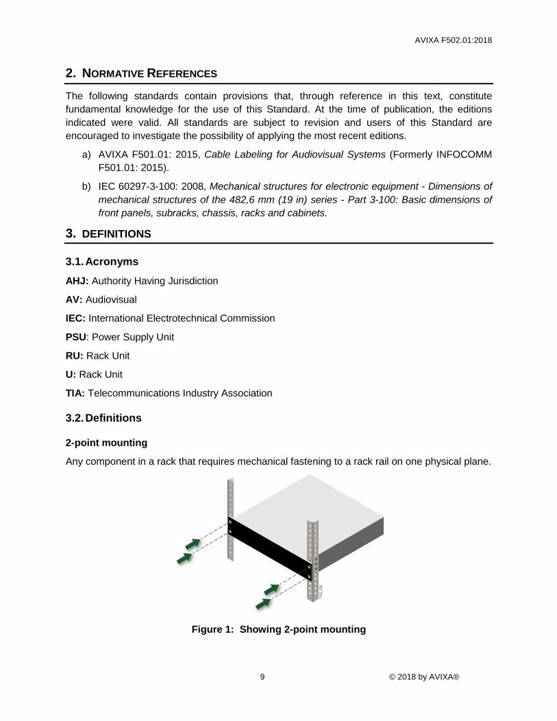
2-point mounting
Any component in a rack that requires mechanical fastening to a rack rail on one physical plane.
Figure 1: Showing 2-point mounting

AVIXA F502.01:2018
© 2018 by AVIXA® 10
4-point mounting
Any component in a rack that requires mechanical fastening to rack rail on two physical planes.
Figure 2: Showing 4-point mounting
AV equipment
Components designed to be part of an AV system may include but are not limited to amplifiers, uninterruptible power supplies, control systems, ethernet switches, video and audio matrices, and baluns.
AV system
A set of components designed and configured to operate as one system to communicate audio and/or video to an audience.
bonding
The provision of electrical connections between conductive parts of an assembly (such as an AV rack frame, side panels, top panels, metal door) for ensuring that all such parts remain at the same electrical potential.
category cables
Standardized twisted pair cable for Ethernet, telecommunications and other purposes (e.g., CAT-5e, CAT-6 as defined by TIA-568).

AVIXA F502.01:2018
11 © 2018 by AVIXA®
external cabling
Any cabling forming part of the AV system that is not wholly contained within the rack(s).
Figure 3: External cabling
ganged
Racks that are physically connected (e.g., bolted, fixed together). A type of multi-rack installation.
inter-rack cabling
Any cabling forming part of the AV system that is passed from one rack to another in a ganged or multi-rack installation.
Figure 4: Inter-rack cabling

AVIXA F502.01:2018
© 2018 by AVIXA® 12
internal cabling
Any cabling forming part of the AV system that is wholly contained within a single rack.
Figure 5: Internal cabling
multi-rack
An installation where more than one rack is used to support the AV system and the racks are co-located but not physically connected (ganged).
non-rack mountable
AV equipment that is not designed to be mounted within an equipment rack conforming to IEC 60297-3-100.
offsite build
Assembly of rack and mounting of AV equipment, rack accessories, internal, and inter-rack cabling into (a) rack(s) that is/are not at the location of final installation.
onsite build
Assembly of rack and mounting of AV equipment, rack accessories, internal, and inter-rack cabling into (a) rack(s) that is/are at the location of final installation.
rack (cabinet, enclosure)
A frame or enclosure with mounting rails to house AV equipment.
rack accessories
Components used in the building of a rack designed to support the AV equipment and cabling. Items may include, but are not limited to, blank panels, lacing (looming) bars, fans, side panels, doors, rack shelves.
rack rail
Structural part of a rack/cabinet providing mounting holes for equipment, front panels, chassis and sub racks. May also be known as rack strip.

AVIXA F502.01:2018
13 © 2018 by AVIXA®
rack unit (RU or U)
One rack unit shall be as defined in IEC 60297-3-100: 1 rack unit = 44.45 mm (1.75 inch) height.
rack mountable
AV equipment that is designed to be mounted within an equipment rack conforming to IEC 60297-3-100, and has a front panel mounting ears/wings with a height in multiples of 1 rack unit. This definition includes an assembly of smaller modules forming a complete rack-mountable unit.
regulatory authority
The municipal, local, county, state, national, or international authority that has governance over the geographic location where the system is being installed. May also be defined as Authority Having Jurisdiction (AHJ).
service loop
Excess cable length provided where length is determined by use: re-termination, replacement or relocation of equipment, or serviceability of the rack.
a) termination service loop – Excess cable length to allow re-termination of cable.
b) equipment service loop – Excess cable length to allow equipment to be removed from the rack for servicing without disconnecting it.
c) external service loop – Excess cable length to allow a rack to be moved for service.
strain relief
The prevention of mechanical stress on a cable, connection, or termination by providing support, typically in the form of horizontal or vertical cable management, using cable ties or hook and loop fasteners.
4. REQUIREMENTS
4.1. Assembly All racks shall be assembled per the manufacturer’s guidelines/instructions and following the manufacturer’s recommended order of assembly.
Rack accessories
A rack assembly shall include all the components and materials that are included with the core rack product, as well as any accessories that are not attached to front, mid, or rear rack rails. In the case of ganged racks that are assembled off-site, the racks should be prepared to be bolted together and checked for fit, even if they will not be ganged together prior to delivery.
Rack accessories shall be installed during rack assembly. These include, but are not limited to:
a) Tops;
b) Pedestals;
AVIXA F502.01:2018
© 2018 by AVIXA® 14
c) Sides;
d) Doors;
e) Door hinges;
f) Vertical cable management;
g) Vertical power distribution strips;
h) Vertical copper grounding bars; and
i) Cable protection.
In some cases, accessories such as doors and side panels should be installed and checked for proper fit, but then temporarily removed to aid in the subsequent loading/populating and cabling of the rack. Some accessories should be fitted into place, but their exact positioning cannot be finalized until AV equipment is loaded/populated. Some accessories, such as security doors and security covers, cannot be installed until AV equipment is loaded/populated.
Once all rack parts and accessories are fully assembled, any final adjustments shall be made before the loading/populating of AV equipment. This includes the final adjustment and location for the front, mid, and rear rack rails, and all vertically mounted accessories such as vertical cable management.
Rack rail locations
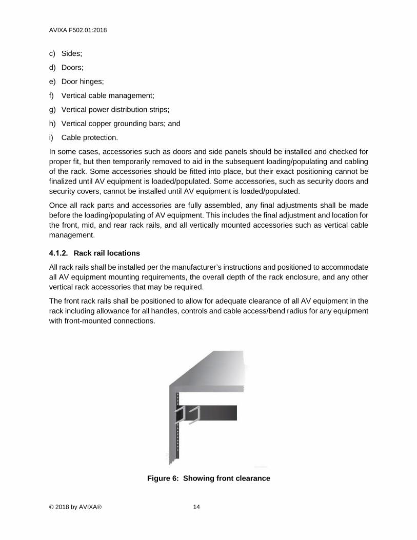
All rack rails shall be installed per the manufacturer’s instructions and positioned to accommodate all AV equipment mounting requirements, the overall depth of the rack enclosure, and any other vertical rack accessories that may be required.
The front rack rails shall be positioned to allow for adequate clearance of all AV equipment in the rack including allowance for all handles, controls and cable access/bend radius for any equipment with front-mounted connections.
Figure 6: Showing front clearance

AVIXA F502.01:2018
15 © 2018 by AVIXA®
The position of the mid and rear rack rails, when required, shall be based on:
a) The overall depth of AV equipment;
b) Any rear AV equipment mounting supports that are required;
c) The number of vertical accessories and cable management lacing bars used; and
d) The overall depth of the rack assembly.
Side view of rack showing rack rails that work with all depth equipment while leaving room for vertical accessories.
• Light gray = Outer rack • Dark gray = Rails • Grid shelves = Varying shelf depths
Courtesy of Middle Atlantic Products
Figure 7: Showing rack rail locations
4.2. Mounting
General
In all cases:
a) All mounting shall adhere to serviceability, electrical interference, cable, and thermal management requirements as part of the design decisions documented prior to the rack building (see the elements outlined in Section 0, Design Decisions).
b) Fixing/fastening of AV equipment to one another is not acceptable unless specified by the manufacturer.
c) All fixings/fasteners shall be fully tightened. The use of fastening methods relying on adhesives is not acceptable.
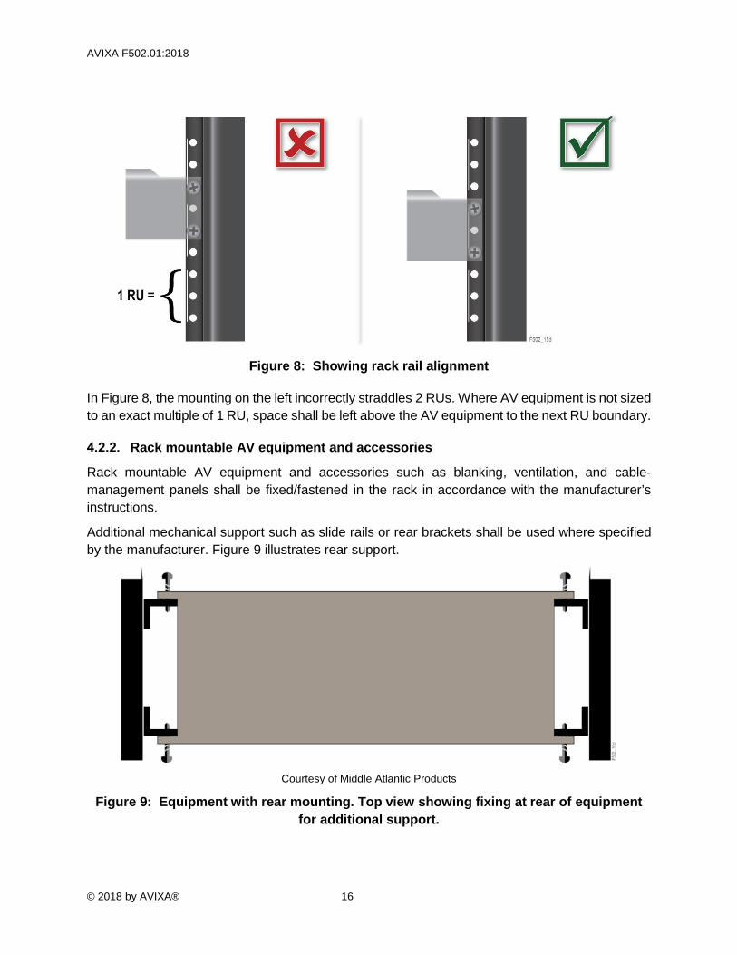
RU alignment All AV equipment shall be mounted in accordance with IEC 60297-3-100. All rack-mountable AV equipment and accessories shall be mounted with the bottom of the mounting aligned to the boundary of the RU division.
AVIXA F502.01:2018
© 2018 by AVIXA® 16
Figure 8: Showing rack rail alignment
In Figure 8, the mounting on the left incorrectly straddles 2 RUs. Where AV equipment is not sized to an exact multiple of 1 RU, space shall be left above the AV equipment to the next RU boundary.
Rack mountable AV equipment and accessories
Rack mountable AV equipment and accessories such as blanking, ventilation, and cable-management panels shall be fixed/fastened in the rack in accordance with the manufacturer’s instructions.
Additional mechanical support such as slide rails or rear brackets shall be used where specified by the manufacturer. Figure 9 illustrates rear support.
Courtesy of Middle Atlantic Products
Figure 9: Equipment with rear mounting. Top view showing fixing at rear of equipment for additional support.

AVIXA F502.01:2018
17 © 2018 by AVIXA®
All rack units at the front of the rack shall be filled with AV equipment, blanking panels, ventilation panels or cable management panels, except for fractional spaces (less than 1 U) left by non-rack mountable AV equipment.
All fixings/fasteners shall be utilized and fully tightened.
Courtesy of Middle Atlantic Products
Figure 10: Showing proper fixed/fastened equipment/accessories in rack
Non-rack mountable AV equipment
Where AV equipment is not rack mountable, the following methods shall be used to mount the AV equipment:
NOTE: Do not cover important information such as serial numbers, power input/output info, power connection pin out, or part numbers.
Rack shelf AV equipment shall be fully secured to the shelf, preferably with a mechanical fixing/fastener.
4.2.3.1.1. Location A single shelf may be used for mounting multiple AV equipment items provided the AV equipment and connections remain accessible. AV equipment with user front-panel controls shall be mounted at the front of the shelf with the user-interface controls facing forward.

AVIXA F502.01:2018
© 2018 by AVIXA® 18
4.2.3.1.2. Fixing/fastening The method of fastening shall be suitable for the device and able to ensure the longevity of the method for mounting. Any fasteners shall be arranged to minimize the intrusion to adjacent rack spaces (see below).
Figure 11: Secure shelf mounting – front view showing fasteners coming from below
(bottom image)
Non-shelf mounted equipment If AV equipment is mounted elsewhere within the rack, it shall not impede access to other AV equipment.
4.2.3.2.1. Locations Acceptable locations include:
a) Cable trays;
b) Horizontal mounting or cable management rails;
c) Rear rack rails; or
d) The rack framework.
AVIXA F502.01:2018
19 © 2018 by AVIXA®
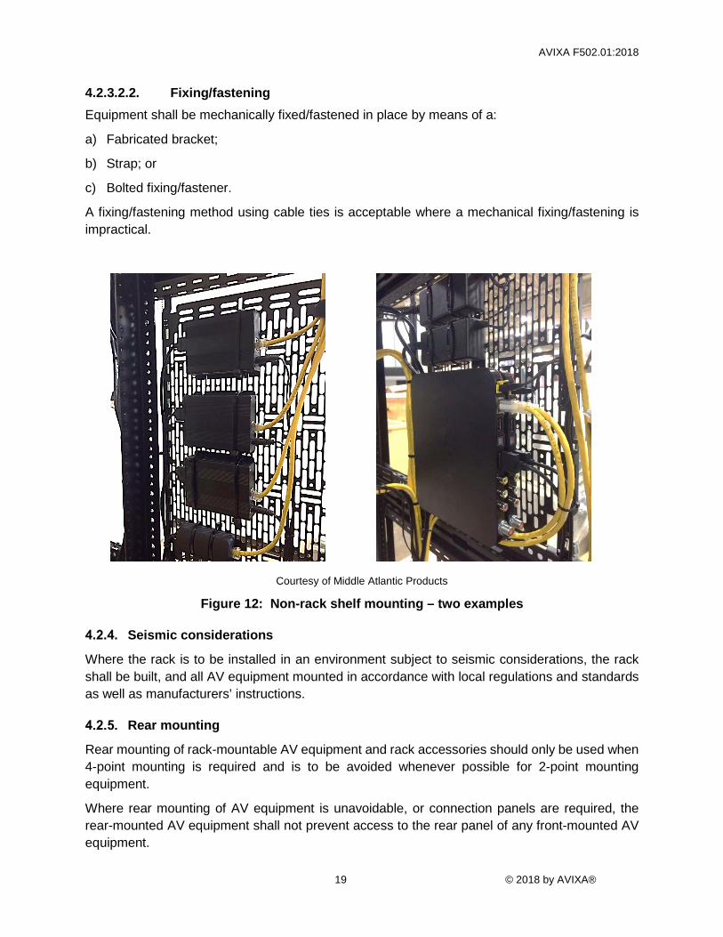
4.2.3.2.2. Fixing/fastening Equipment shall be mechanically fixed/fastened in place by means of a:
a) Fabricated bracket;
b) Strap; or
c) Bolted fixing/fastener.
A fixing/fastening method using cable ties is acceptable where a mechanical fixing/fastening is impractical.
Courtesy of Middle Atlantic Products
Figure 12: Non-rack shelf mounting – two examples
Seismic considerations
Where the rack is to be installed in an environment subject to seismic considerations, the rack shall be built, and all AV equipment mounted in accordance with local regulations and standards as well as manufacturers’ instructions.
Rear mounting
Rear mounting of rack-mountable AV equipment and rack accessories should only be used when 4-point mounting is required and is to be avoided whenever possible for 2-point mounting equipment.
Where rear mounting of AV equipment is unavoidable, or connection panels are required, the rear-mounted AV equipment shall not prevent access to the rear panel of any front-mounted AV equipment.
AVIXA F502.01:2018
© 2018 by AVIXA® 20
Use of a rear rack rail for cable management is permissible provided it conforms with Section 4.3.2 of this Standard.
Operational and maintenance access
The rack shall be constructed so that access is maintained to all AV equipment for operational and maintenance purposes. Maintenance considerations shall include requirements for access to controllers, rear panel controls, and AV equipment mechanical fixings/fasteners.

AVIXA F502.01:2018
21 © 2018 by AVIXA®
4.3. Cable management Elements of proper cable management include cable handling, serviceability, and signal separation. Careful attention shall be given to placement and support of individual cables and cable looms in horizontal and vertical space.
Signal separation
Where possible, cables should be dressed in line with the minimum distances recommended in Table 1 unless specified in project or manufacturer documentation. When this is not possible, the cables should be dressed to maximum-achievable separation.
Power cables shall be bundled separately from signal cables.
Table 1: Recommended signal separation
RECOMMENDED MINIMUM SEPARATION BETWEEN CABLES
Signal Type
Common Level(s)
Audio Micro-Phone Level
Audio Line Level
Video Cable
Data Twisted
Pair Cable
RF Coax Cable
Speaker Cable
AC Power Cable
Audio Micro- Phone Level
-60 dBV (0.001 volt) to -40 dBV (0.010 volt)
No Spacing Required
Separate Bundles
Separate Bundles
100 mm (≈4 in) minimum
100 mm (≈4 in) minimum
100 mm (≈4 in) minimum
300 mm (≈12 in) minimum
Audio Line Level
0 dBV (1.000 volt)
Separate Bundles
No Spacing Required
Separate Bundles
Separate Bundles
50 mm (≈2 in) minimum
50 mm (≈2 in) minimum
100 mm (≈4 in) minimum
Video Cable
0.8 volts Separate Bundles
Separate Bundles
No Spacing Required
Separate Bundles
50 mm (≈2 in) minimum
50 mm (≈2 in) minimum
50 mm (≈2 in) minimum
Data Twisted Pair Cable
max 125 VDC, 30 watts (add signal level)
100 mm (≈4 in) minimum
Separate Bundles
Separate Bundles
No Spacing Required
Separate Bundles
Separate Bundles
50 mm (≈2 in) minimum
RF Coax Cable
0 dBmv to 50 dBmv
100 mm (≈4 in) minimum
50 mm (≈2 in) minimum
50 mm (≈2 in) minimum
Separate Bundles
No Spacing Required
Separate Bundles
50 mm (≈2 in) minimum
Speaker Cable
1 watt to 1,000 watts, max 100 VRMS
100 mm (≈4 in) minimum
50 mm (≈2 in) minimum
50 mm (≈2 in) minimum
Separate Bundles
Separate Bundles
No Spacing Required
50 mm (≈2 in) minimum
AC Power Cable
120/240 volts 50/60 Hz
300 mm (≈12 in) minimum
100 mm (≈4 in) minimum
50 mm (≈2 in) minimum
50 mm (≈2 in) minimum
50 mm (≈2 in) minimum
50 mm (≈2 in) minimum
No Spacing Required
Cable planning and placement
Planning and placement of both horizontal and vertical cable management shall consider the following factors:
a) The amount of cable management (e.g., cable trays) required to meet signal separation.

AVIXA F502.01:2018
© 2018 by AVIXA® 22
b) The amount of cable management required to allow space for external cabling if built offsite.
Courtesy of Visualization Limited
Figure 13: Double vertical cable management
c) The placement of horizontal cable management to provide support in line with bend radius, strain relief, serviceability, thermal management, and labeling requirements. See Figure 14.
Courtesy of Middle Atlantic Products
Figure 14: Horizontal cable management
d) Airflow (both intake and exhaust) shall not be blocked.
Cable strain relief
Cable entry into the rack shall have strain relief and edge protection to avoid damage to the cables.

AVIXA F502.01:2018
23 © 2018 by AVIXA®
The bend radius requirements of cables shall be followed. The specific permissible bend radii will be determined by the manufacturers of the individual cables. However, a general guideline is that the cables shall be bent to a radius no less than four times the diameter of the cable, as in Figures 15 and 16.
Figure 15: Bend radius
Courtesy of Visualization Limited
Figure 16: Bend radius of loomed cables
Power lacing
Power supply units shall be situated locally to the power input of the AV equipment being supplied. This allows for future serviceability and swap out of the power supply unit without re-dressing cabling.

AVIXA F502.01:2018
© 2018 by AVIXA® 24
The low voltage cable from power supply units shall be cut and re-terminated when possible (see Figure 17). Bundling of this element is permitted for molded connectors (see Figure 18).
Courtesy of Visualization Limited
Figure 17: Shortened low voltage PSU
Courtesy of Visualization Limited
Figure 18: Bundled low voltage PSU cable
Power and signal cable length
Sufficient cable length shall be provided to accommodate future serviceability of racks and equipment (see Section 3.2 under Definitions for information on service loops and cable length).

AVIXA F502.01:2018
25 © 2018 by AVIXA®
If using fixed-length pre-terminated cables, excess length shall not be coiled (see Figure19, left image). Any additional length shall be dressed vertically or horizontally considering bend radius (see Figure 19, right image).
Courtesy of Middle Atlantic
Figure 19: Incorrect coiling of excess cable (left) and correct dressing considering bend radius (right).
When pre-terminated cables of an appropriate length are not available, cables may only be shortened provided manufacturer warranties are not voided and regulatory requirements are met.
Cables shall be laced in a C shape, not an L, as shown in Figure 20.
Courtesy of Visualization Limited
Figure 20: Cable lacing
Equipment and rack service loops
Service loops shall be provided to allow for re-termination of cables (where field terminatable), replacement or relocation of equipment, and general maintenance and serviceability of the equipment rack.

AVIXA F502.01:2018
© 2018 by AVIXA® 26
Where an equipment rack is not fixed in position and must be moved to give service access, an external service loop shall be provided on all external cabling entering the rack. The external service loop shall be long enough to allow the rack to be moved to a position where the rear of the equipment may be accessed.
Where an equipment rack is fixed in position and the rear of the equipment rack is not accessible, an equipment service loop shall be provided to all equipment. The equipment service loop shall be long enough to allow the equipment to be removed from the front of the rack without first disconnecting the cables.
Each cable that may be field terminated shall be provided with a termination service loop to allow the cable to be re-terminated at least twice. Where an equipment service loop is provided that will allow the cables to be re-terminated, a separate termination service loop is not required.
Figure 21 shows service loops for both termination and Figure 22 shows equipment servicing.
Courtesy of Visualization Limited
Figure 21: Termination service loop
AVIXA F502.01:2018
27 © 2018 by AVIXA®
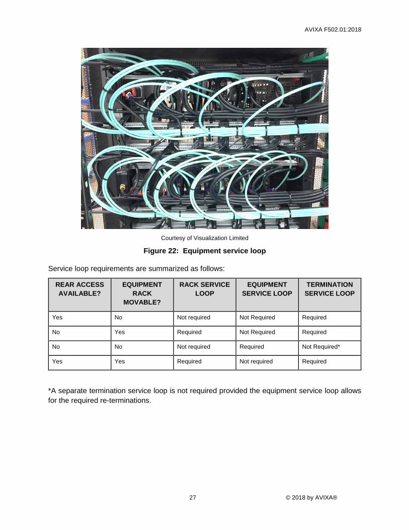
Courtesy of Visualization Limited
Figure 22: Equipment service loop
Service loop requirements are summarized as follows:
REAR ACCESS AVAILABLE?
EQUIPMENT RACK
MOVABLE?
RACK SERVICE LOOP
EQUIPMENT SERVICE LOOP
TERMINATION SERVICE LOOP
Yes No Not required Not Required Required
No Yes Required Not Required Required
No No Not required Required Not Required*
Yes Yes Required Not required Required
*A separate termination service loop is not required provided the equipment service loop allows for the required re-terminations.

AVIXA F502.01:2018
© 2018 by AVIXA® 28
Figure 23: Showing service loop to move the rack
Cable bundling/looming
Cables shall be supported in bundles or looms to keep cables organized and protected at entry points.
Cables shall be combed prior to looming unless manufacturer states otherwise. Effort should be made to minimize the amount of crossing. Cable crossing should not occur underneath any form of wire, cable or hook and loop tie.
Any excess material from wire and cable ties shall be removed and cut flush. Hook and loop shall be used on all category cables, coaxial, and fiber cables. Spacing between cable ties shall be three (3) times diameter of the loom or 10 cm (~4 inches), whichever is smaller and unevenly spaced.1 Figures 24 and 25 show examples of cable tie spacing.
NOTE: Uneven spacing may be undiscernible to the naked eye.
1 (IPC Task Group (7-31f), WHMA Industry Technical Guidelines Committee (ITGC) 2006)

AVIXA F502.01:2018
29 © 2018 by AVIXA®
Courtesy of Visualization Limited
Figure 24: Cable tie spacing
Courtesy of Visualization Limited
Figure 25: Hook and loop used in place of cable ties

AVIXA F502.01:2018
© 2018 by AVIXA® 30
Ties shall not be applied excessively tight; should be spaced at irregular intervals as shown in Figure 26; and shall comply with the cable and wire tie manufacturer specifications.2
Figure 26: Overtightening – incorrect (left) and correct (right) bundling
Inter-rack cabling for ganged and multi-rack scenarios
Racks shall be interconnected in one of three ways:
1. External cabling entering from above shall be dressed vertically up through top of rack with possible use of cable ladder to route between racks.
2. External cabling entering from below shall be dressed vertically down through bottom of rack with possible use of riser bases or raised floor to route between racks.
3. Internal cabling, if required: Additional horizontal lacing bars shall be used for cable interconnectivity between racks. This method may only be used for ganged racks.
Power lacing between interconnecting racks shall meet the separation requirements in Section 4.3.1.
4.4. Finishing
Bonding
Rack bonding shall be undertaken. Refer to project documentation and local regulations for requirements.
2 ANSI/TIA-568-C.0, Generic Telecommunications Cabling for Customer Premises

AVIXA F502.01:2018
31 © 2018 by AVIXA®
Cable labeling
All cabling within the rack shall be labelled following the requirements of the AVIXA F501.01:2015, Cable Labeling in Audiovisual Systems.
AV equipment labeling
Labeling shall be machine-printed (or engraved) and shall be consistent, durable, accurate, and visible without dismantling sub-assemblies.
In the absence of defined labeling requirements within the project documentation, the following requirements shall be observed:
a) All AV equipment shall be identified as to its function in the system, such as “radio mic 1,” “surround amplifier,” or “video matrix.” AV equipment functional labels should be fixed to the rack at the location of the AV equipment, and not to the AV equipment itself.
b) All AV equipment controls shall be labeled as to their function within the system, such as “rear left volume” or “floorbox 1 input.”
c) All switching matrices with front-panel button-per source and button-per-destination shall be provided with designation labels with meaningful information, such as “projector HDMI” or “table input 1.”
d) All patch panels shall be labeled with a strip consisting of machine-printed letters, numbers, and/or symbols to provide information about the function of that connector.
e) Power cables shall be labeled.
f) Outlets and/or fuses/circuit breakers on mains distribution units that have the capability shall be labeled with details of the equipment that they serve.
All connection panels shall be labelled with the function of the connector and/or the cable number reference in accordance with the design documentation.
Courtesy of Visualization Limited
Figure 27: Panel labeling

AVIXA F502.01:2018
© 2018 by AVIXA® 32
Courtesy of Visualization Limited
Figure 28: AV equipment labels
Where AV equipment serial numbers are not visible once the AV equipment is mounted within the rack, a separate serial number label shall be affixed to the rear panel of the AV equipment.
Rack cleaning
At the completion of the build process, the rack shall be cleaned to remove all dirt, dust, and debris. All temporary labeling, ties, and tape shall be removed. All stray wire pieces, cable off-cuts, tie cut-offs, and other debris shall be removed from the rack.

AVIXA F502.01:2018
33 © 2018 by AVIXA®
5. VERIFICATION In addition to Section 4, Requirements, conformance to this Standard includes conformance to items from ANSI/INFOCOMM 10:2013, AV Systems Performance Verification. Relevant items are reproduced below.
For verification purposes, requirements contained in project documentation take precedence over requirements detailed in this Standard. In the absence of defined requirements within project documentation, the requirements contained in this Standard shall be used.
RELEVANT ITEMS FROM ANSI/INFOCOMM 10:2013, AV Systems Performance Verification
CABL-100 CABLE BEND RADIUS Verify that cables are not bent beyond their minimum bend radius as specified in cable data sheet to maintain signal integrity as defined in the project documentation. Project documentation may state a larger radius to allow for a safety margin.
CABL-101 AV CONNECTOR PLATE INPUT AND OUTPUT LABELING
Verify that all AV connector plate inputs and outputs are labeled as defined in the project documentation.
CABL-102 AV CONNECTOR SEATING Verify that all AV connectors are correctly keyed, seated, and latched to respective connection points as defined in the project documentation. Conditions where physical parameters exceed the connector's ability to maintain full seating should be resolved as defined in the project documentation.
CABL-103 AV CONNECTOR VERIFICATION Verify that all AV cable terminations are made securely and meet the recommendations of the connector and cable manufacturer(s), published standards, and requirements defined in the project documentation.
CABL-104 AV EQUIPMENT POWER CABLE MANAGEMENT
Verify that all AV equipment power cables are managed as defined in the project documentation. Verify that cables are managed in a uniform and acceptable manner so as not to compromise safety/OEM warranty, AV signal quality, and/or future field service.
CABL-105 AV SYSTEM CABLE LABELING Verify that all AV system cables are identified by a unique ID as defined in the project documentation. Verify that this unique ID is displayed permanently at both ends of the cable, is legible, and is positioned where it can be seen without undue disturbance.
CABL-106 CABLE SEPARATION Verify that rack cables have appropriate separation according to signal type and level as defined in the project documentation.
CABL-107 CABLE SUPPORTS Verify that all cables are supported throughout their lengths as defined in the project documentation.
CABL-108 CABLE TIES Verify that, where appropriate, cable ties are used to secure the cables, are correctly tensioned, and that the

AVIXA F502.01:2018
© 2018 by AVIXA® 34
RELEVANT ITEMS FROM ANSI/INFOCOMM 10:2013, AV Systems Performance Verification correct type of cable tie(s) is used as defined in the project documentation.
CABL-109 CABLES BUNDLED BY TYPE Verify that cables are only bundled together when their construction, signal type, and signal level are compatible and will not cause measurable crosstalk or interference between cables.
CABL-110 CABLES DRESSED Verify that cables are dressed to ensure that all rack and site cables are installed to provide serviceability, safety, and aesthetics as defined in the project documentation.
CABL-111 PATCH PANEL CONFIGURATION
Verify that all patch panels have been correctly wired and configured as defined in the project documentation.
CABL-112 PATCH PANEL LABELING Verify that all patch panels have been labeled as defined in the project documentation. Verify that all labeling is machine-printed, consistent, durable, accurate, and legible.
CABL-113 TERMINATION STRESS Verify that all cable terminations have been completed and adequately supported to minimize stress on the termination point and/or connector.
CABL-114 AV CONNECTOR PLATE CONSISTENT LABELING
Verify that AV connector plates have consistent labeling throughout the project as defined in the project documentation.
CABL-115 AV SYSTEM CABLING VERIFICATION
Verify that all cabling is the correct type and routed correctly from point to point as defined in the project documentation.
CABL-116 CABLE LENGTH REQUIRED FOR SERVICEABILITY
Verify the availability of sufficient cabling so the device can be placed in a serviceable location as defined in the project documentation.
DOC-117 USER MANUALS Verify that manufacturer’s user manuals are delivered to the owner in a format defined in the project documentation (e.g., binders, PDFs), or dispose of the manuals in a responsible manner (recycling) if the owner specifies that they do not wish to receive the manuals. Integrator- or programmer-created manuals and documentation shall be delivered to the owner in a format defined in the project documentation.
ELEC-101 GROUNDING/EARTHING Verify that all elements of the AV system are correctly bonded to an electrical ground/earth in accordance with the requirements of the regulatory authority and as defined in the project documentation.
ELEC-102 MAINS VOLTAGE SUB-DISTRIBUTION INTEGRITY
Verify that all electrical sub-distribution systems provided by the AV contractor in equipment racks, furniture, and similar structures meet local regulatory requirements for electrical integrity.

AVIXA F502.01:2018
35 © 2018 by AVIXA®
RELEVANT ITEMS FROM ANSI/INFOCOMM 10:2013, AV Systems Performance Verification
PHYSI-101 AV RACK AIR FLOW AND TEMPERATURE PERFORMANCE
Verify that the AV rack(s) provides the air flow as required in the project documentation. Verify that the temperature in the AV rack has been measured and is within tolerances defined by manufacturers’ guidelines and the project documentation. This verification item shall require a metric to be verified.
PHYSI-102 EQUIPMENT SECURITY Verify that equipment is secured as defined in the project documentation. Verify that all security systems, devices, and manufacturer security accessories are installed and verified to be operating as defined in project documentation. Verify that keyed devices have been keyed as defined in the project documentation and devices requiring configuration have been configured as defined in the project documentation and are verified to be operating within specification.
PHYSI-103 AV EQUIPMENT LABELING Verify that all AV equipment has been labeled in accordance with the requirements of the project documentation. All labeling must be consistent, durable, accurate, and visible without dismantling of sub-assemblies.
PHYSI-104 PLUMB AND LEVEL/SQUARE Verify that all AV equipment has been installed, aligned, or angled correctly as defined in the project documentation. Level and plumb are the default requirement unless angles or other alignments are defined in the project documentation.
PHYSI-106 AV EQUIPMENT LOCATION Verify that AV equipment is installed at the location and/or in the rack or enclosure as defined in the project documentation. Equipment is installed per the elevation or other specification provided by the project documentation or the manufacturer’s specification.
PHYSI-107 AV RACK CLEANLINESS Verify that all components installed in AV equipment racks are free from dirt, dust, water, or any other element that would compromise the performance and/or longevity.
PHYSI-108 NON-END-USER CONTROLS PROTECTION
Verify that installed items with user-facing controls that are not intended for end-user access have been covered, disabled, or otherwise secured to prevent end-user operation.
SERV-101 ABILITY TO MAINTAIN AND SERVICE EQUIPMENT
Verify that all equipment is accessible and capable of being maintained, serviced, cleaned, or adjusted as necessary. Verify that all equipment requiring regular cleaning or maintenance is accessible without requirement for special equipment or tools that would disrupt the normal use of the facility and systems therein.
SERV-102 INPUT AND OUTPUT PANEL ACCESSIBILITY
Verify that all input and output panels are accessible and meet all requirements for user access and placement.
AVIXA F502.01:2018
© 2018 by AVIXA® 36
ANNEX A – DESIGN CONSIDERATIONS (INFORMATIVE) The conditions below are part of a larger set of considerations addressed during the design phase. They are included for informational purposes only and not intended to be a full representation of design phase elements.
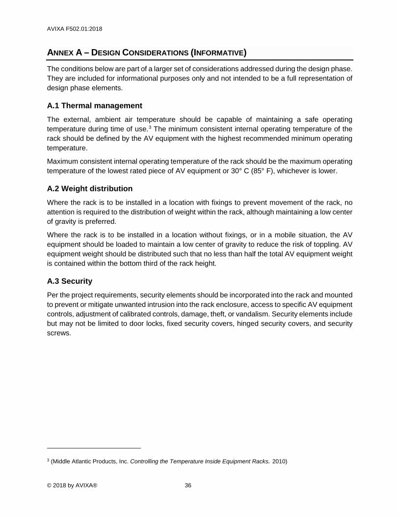
A.1 Thermal management The external, ambient air temperature should be capable of maintaining a safe operating temperature during time of use.3 The minimum consistent internal operating temperature of the rack should be defined by the AV equipment with the highest recommended minimum operating temperature.
Maximum consistent internal operating temperature of the rack should be the maximum operating temperature of the lowest rated piece of AV equipment or 30° C (85° F), whichever is lower.
A.2 Weight distribution Where the rack is to be installed in a location with fixings to prevent movement of the rack, no attention is required to the distribution of weight within the rack, although maintaining a low center of gravity is preferred.
Where the rack is to be installed in a location without fixings, or in a mobile situation, the AV equipment should be loaded to maintain a low center of gravity to reduce the risk of toppling. AV equipment weight should be distributed such that no less than half the total AV equipment weight is contained within the bottom third of the rack height.
A.3 Security Per the project requirements, security elements should be incorporated into the rack and mounted to prevent or mitigate unwanted intrusion into the rack enclosure, access to specific AV equipment controls, adjustment of calibrated controls, damage, theft, or vandalism. Security elements include but may not be limited to door locks, fixed security covers, hinged security covers, and security screws.
3 (Middle Atlantic Products, Inc. Controlling the Temperature Inside Equipment Racks. 2010)

AVIXA F502.01:2018
37 © 2018 by AVIXA®
ANNEX B PROCESS MAP (INFORMATIVE)
AVIXA F502.01:2018
© 2018 by AVIXA® 38
ANNEX C – REFERENCES (INFORMATIVE) The following standards contain information that support the application of this Standard. All standards are subject to revision and users of this Standard are encouraged to investigate the possibility of applying the most recent editions. At the time of publication, the editions indicated were valid.
ANSI/INFOCOMM 10:2013, Audiovisual Systems Performance Verification. Fairfax, VA: InfoComm International.
AVIXA F501.01:2015, Cable Labeling for Audiovisual Systems (Formerly INFOCOMM F501.01:2015). Fairfax, VA.
Institution of Engineering and Technology. BS 7671:2018, Requirements for Electrical Installations, IET Wiring Regulations, Eighteenth Edition (Electrical Regulations). London, England: 2018.
International Electrotechnical Commission. IEC 60297-3-100:2008, Mechanical structures for electronic equipment - Dimensions of mechanical structures of the 482,6 mm (19 in) series - Part 3-100: Basic dimensions of front panels, subracks, chassis, racks and cabinets. Geneva: 2008.
IPC and Wiring Harness Manufacturers Assoc. IPC/WHMA-A-620C, Requirements and Acceptance for Cable and Wire Harness Assemblies. Arlington Heights, IL: 2017.
Middle Atlantic Products, Inc. Controlling the Temperature Inside Equipment Racks. Fairfield, NJ: Middle Atlantic Products, Inc., 2010.
Systimax Solutions. Power Separation Guidelines for SYSTIMAX(R) Installations. Hickory, NC: CommScope, 2011.
Telecommunications Industry Association. ANSI/TIA-568-C.0, Generic Telecommunications Cabling for Customer Premises. Arlington, VA: 2015.
Telecommunications Industry Association. TIA-568.1-D, Commercial Building Telecommunications Cabling Standard. Arlington, VA: 2015.
Telecommunications Industry Association. TIA-569-D, Telecommunications Pathways and Spaces. Arlington, VA: 2015.
TG 30, Pathway Separation Between Telecommunication Cables and Power Cables. 2. Atlanta, GA: Superior Essex, 2014.