RACK AND PINION DRIVE ADOR CROCO - Moscow … · rack and pinion drive ador croco installation...
27
RACK AND PINION DRIVE ADOR CROCO INSTALLATION MANUAL FORD TRANSIT 2 03.02.2017 automatic doors
Transcript of RACK AND PINION DRIVE ADOR CROCO - Moscow … · rack and pinion drive ador croco installation...

RACK AND PINION DRIVEADOR CROCO
INSTALLATION MANUAL
FORD TRANSIT 2
03.02.2017
automaticdoors


3CONTENTS
1.1 General information..........................................................................................................................................................................................41.2 General information, operating safety and list of tools....................................................................................................6
2.1 Main wiring harness..........................................................................................................................................................................................72.2 Connection diagram for rack-and-pinion drive...........................................................................................................................82.3 Main wiring harness layout........................................................................................................................................................................92.4 Controller installation and minus terminal connection........................................................................................................102.5 Latch actuator and actuator wiring harness installation....................................................................................................112.6 Layout of sliding door limit switch.....................................................................................................................................................132.7 Positive wire connection to power supply and control button installation.......................................................14
3.1 Rack mounting...................................................................................................................................................................................................153.2 Cradle mounting..............................................................................................................................................................................................173.3 Preliminary preparation..............................................................................................................................................................................18
4.1 The first cycle of rack-and-pinion drive.......................................................................................................................................19 4.2 Rack-and-pinion drive adjustment.....................................................................................................................................................20 4.3 Mounting of door drive cover and decorative flange.........................................................................................................21 4.4 Warning sticker location............................................................................................................................................................................22 4.5 Mounting of outer handle cover and inner handle cover..............................................................................................234.6 Control and adjustment...........................................................................................................................................................................24

4 1.1 GENERAL INFORMATION
Sliding door contacts
Cradle Rod Rack Main wiring harness
Latch actuator Limit switch
Door drive Control buttonController
Terminal +12V/30A(to plus terminal of power supply)
Additionalbutton
Remotecontrol
This rack-and-dpinion drive is designed to open and close sliding door in Ford Transit 2 minibus.
The layout of the units is shown on the base of the universal minibus prototype.
NOTE This manual discribes the installation of the rack-and-pinion drive with the widest range of drive units. If you install the rack-and-pinion drive without latch actuator or remote control then you have to omit the corresponding items of the manual.
SPEC CHARACTERISTICS:
CROCO drive is designed for opening and closingdoors in minibuses working as taxi buses.
Power consumption (rating), watt
70 Wt
Power consumption (max), watt
250 Wt
Door-opening time, sec (it depends upon the opening width adjustment)
2 s
Door-closing time, sec(it depends upon the opening width adjustment)
2 s
Category temperature range, °C
from -25 °C up to +40°C
Maximum slop for the door to be closed
10°
ResourcesNot less than150000 cycles
!!
51.1 ОБЩИЕ СВЕДЕНИЯ
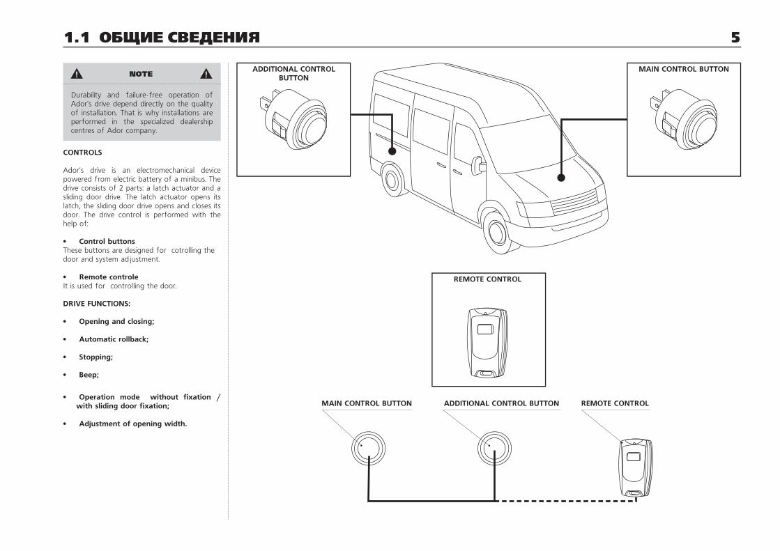
Durability and failure-free operation of Ador's drive depend directly on the quality of installation. That is why installations are performed in the specialized dealership centres of Ador company.
CONTROLS
Ador's drive is an electromechanical device powered from electric battery of a minibus. The drive consists of 2 parts: a latch actuator and a sliding door drive. The latch actuator opens its latch, the sliding door drive opens and closes its door. The drive control is performed with the help of:
• Control buttonsThese buttons are designed for cotrolling the door and system adjustment.
• Remote controleIt is used for controlling the door.
DRIVE FUNCTIONS:
• Opening and closing;
• Automatic rollback;
• Stopping;
• Beep;
• Operation mode without fixation / with sliding door fixation;
• Adjustment of opening width.
REMOTE CONTROL
REMOTE CONTROLADDITIONAL CONTROL BUTTONMAIN CONTROL BUTTON
ADDITIONAL CONTROLBUTTON
MAIN CONTROL BUTTON!! NOTE

6
Torch…………………………………………...............................................1 Sliding calipers……………………………….............................................1Power drill…………………………………...............................................….1Hacksaw…………………………………..................................................….1 Multimeter……………………………………..............................................1 Cutting nippers……….................………….........................................1 Rivet nut..........................................................................................15Industrial spirit................................................................................1 There may appear some edge fin after making holes, finally it leads to the damage of the paint coat. There are symbolic notations on the places where some treatment is required:
— Remove edge fin; — Unedge; — Treat with acid-free antirust liquid.
For example, the indicated holes must be treated with antirust liquid.
1.2 GENERAL INFORMATION, OPERATING SAFETY AND LIST OF TOOLS
OPERATING SAFETY
Rack-and pinion drive installation is connected with some modification of minibus body. The parts of the body are mainly made of sheet metal that is why there is a great danger of getting injured for the reason of sharp edges appeared after modification, or because of the movable parts of your hand cutting tools. Observe safety regulations while installing the drive, provide adequate clearance inside the bus. Arrange all the units and tools before assemblage, remove unnecessary things
Failure-free operation and drive durability depend upon your observance of the installation instructions and also upon the correct positional relationship of the units and components. All the surfaces should be thoroughly marked before making mounting holes. Inspect the positional relationship of the units and components. Having fixed the unit, check up its location.
The drive is an electromechanical device thus one must observe electricity safiety rules. Keep contacts clean, failure-free operation and reliability depend on it.
LIST OF TOOLS
Clip remover…………………………......................................................1Set of interchangeable heads from10mm up to 17mm……......................................................1 setRiveter……………….................................................................................1Riveter for blind rivet nuts GESIPA, GBM10...........1Center punch..................................................................................1Spanner wrenches............................................…..............1 setMetal ruler…………………...................................................................1Hammer……………………...................................................................1Set of Allen keys……...........………………........................................1Set of star screwdrivers……………............................................1Knife………………….................................................................................1Blade screwdriver……………..........................................................1 Сross-slotted screwdriver…………..........................................1 Combination pliers…………………..................................................1 Wire…………………………………….......................................................3 mDrills 2,5; 3,2; 5; 6,5; 9…………………..................................1Taper drill from 4mm up to 24mm…............………...1Ratchet…………………………..................................................................1 Electrical socket extender…………..................…...............…....1
2 holes Ø12
2 holes Ø12

72.1 MAIN WIRING HARNESS
Blue wire terminal isfor immovable contacts
Green wire terminal isfor immovable contacts
Connector of 30A fuse
30A fuse
Plus red wire terminal (+12V)of 30A fuse comes toplus terminal of power supply
Connector of maincontrol button
Minus black (thin) wireterminal is connectedwith body of a bus
Minus blue wire terminal isconnected with body of a bus
Minus black (thick) wire terminalis connected with body of a bus
Main wiring harnessconnector comesto controller
Main wiring harnessconnector with 2 pinsis connected withadditional buttonconnector and remote control
Plus red wire comesto remote control

8 2.2 CONNECTION DIAGRAM FOR RACK-AND-PINION DRIVE
1. Rack-and-pinion drive2. Controller3. Drive connector (black, red, gray-black, blue-black, gray-white, white-red)4. Connector of controller wiring harness (black, red, gray-black, blue-black, gray-white,5. Connector of controller wiring harness (red, black, green, yellow-blue, yellow)6. Connector of main wiring harness (green, red, blue, black (thick), black (thin), yellow-blue)7. Minus wire terminals (black (thick), black (thin), blue) are connected with body of a bus.8. Main wiring harness9. Additional button10. Connector of additional button (black, yellow-blue)11. Blue wire terminal of main wiring harness comes to immovable contacts.12. Green wire terminal of main wiring harness comes to immovable contacts.13. Immovable contacts14. Movable contacts15. Blue wire terminal of actuator wiring harness comes to movable contacts.16. Green wire terminal of actuator wiring harness comes to movable contacts.17. Blue wire terminal of actuator wiring harness18. Green wire terminal of actuator wiring harness19. Latch actuator20. Wiring harness of actuator21. Red wire connector of 30A fuse22. 30A fuse23. Plus red wire terminal (+12V) comes to plus terminal of power supply24. Main control button25. Main control button connector (black, yellow-blue)26. Blue wire terminal of actuator27. Green wire terminal of actuator28. Remote control
10
828
9ДУ
1 3 4 2
5 6
7
2615
16
141311
12
20
21 22
23
25 24
1917
2718

92.3 MAIN WIRING HARNESS LAYOUT
+12V
Branch №2
Branch №5
Branch №3
Branch №4
Branch №1
Pic. 1
Remove shown connectors from the main wiring harness before laying. Install them again after laying, if necessary put some marks.
Main wiring harness is located inside the cavities.
Main wiring harness is recommended to be laid as shown in picture 1 starting with line ¹1.
NOTE
All wires must be protected and firmly attached to avoid any breakage, abrasion or chafing.

10 2.4 CONTROLLER INSTALLATION AND MINUS TERMINAL CONNECTION
Pic. 2
Ø 13 Ø6,5
Remove the paint around the hole thoroughly
Pic. 3
Bolt Ì6õ14
Toothed washer
Nut Ì6
Minus wireterminals «-»
Self-tapping screw 4,2x16
Controller
Minus wireterminal «-»
Pic. 1
Install a controller in the side recess of the sliding door and fix it with 2 self-tapping screws 4,6x16 as shown in picture 1.
Make a hole 6,5mm on the inner side near the controller (picture 1) for mounting minus wire terminal. Remove the paint around the hole thoroughly in order to make a good contact (picture 2).
Use bolt M6x14, toothed washer and nut M6 to fix minus wire terminal «-» (pic. 3). After tightening bolt M6 coat the damaged area with antirust liquid.

112.5 LATCH ACTUATOR AND ACTUATOR WIRING HARNESS INSTALLATION
Pic. 1
Actuator wiringharness
Blue wire of actuatorwiring harness
Green wire ofactuator wiringharness
Movable contacts
Latch actuator cable
Standard cable
Attaching pointof latch actuator
Blue wire of actuatorwiring harness
Green wire ofactuator wiringharness
Blue wire of actuator
Green wire of actuator
Latch actuator
1. Latch actuator is located inside a door (pic-ture 1).2. Make holes 5 mm using marking (picture 2).3. Put a latch actuator bracket into a doorn re-cess, fix it with rivets 4,8x12 (picture 2).4. Open a cover of the adaptor coupling and pull out a standard cable (picture 3).

12 2.5 LATCH ACTUATOR AND ACTUATOR WIRING HARNESS INSTALLATION
Cable holder
Pic. 4
73
18
16
115
Lock actuatorAdaptor coupling
Standard cable
Latch actuator cable
3 îòâ. 5
Pic. 2
65
Pic. 3
Pull out a standard cable
Open a cover
Adaptor coupling
Pic. 5
Insert a latch actuator cable
Close a cover
5. Insert standard cable into the latch actuator (picture 4).6. Insert a latch actuator cable into the adaptor coupling and close its cover (picture 5).7. Close the door completely and adjust the length of the latch actuator cable with the help of the cable holder (picture 4).
NOTE
Cable overtightening leads to the failure in releasing the central locking system.
8. Connect the latch actuator according to picture 1.
!!

132.6 LAYOUT OF SLIDING DOOR LIMIT SWITCH
MOVABLE CONTACTS
Movable contacts are located on the front mounting face of the sliding door (pic. 1).
1. Make holes according to your marking (pic.1).2. Connect actuator wiring harness to movable contacts (blue wire to upper contact, green wire to lower contact (pic. 1 page 11).3. Fix movable contacts using self-tapping screws.
IMMOVABLE CONTACTS
Immovable contacts are located on the front doorway pillar (pic.2).
1. Put some motor grease on the tips of the movable contacts.2. Close and open the door.3. Using grease marks left on the doorway pillar, make some marking and then make holes (pic. 2)4. After mounting the main wiring harness connect blue wire to the upper contact and green wire to the lower contact. Fix immovable contacts on the doorway pillar using self-tapping screws (pic. 2).
The movable and immovable parts of the limit switch are located in such a way that inscription «Autodoor» must be on top.
Pic. 1
MOVABLE CONTACTS
60
1858
24
Self-tappingscrew 3,9x16
2 holes 14 Ø
2 holes 2,5 Ø
Pic. 2
Self-tapping screw 3,9x16 IMMOVABLE CONTACTS
Ø20
58
99
Blue wire
Green wire
Immovable contacts
Marks left by contacts (grease marks)
!! NOTE

142.7 POSITIVE WIRE CONNECTION TO POWER SUPPLY
AND CONTROL BUTTON INSTALLATION
Pic. 1 Pic. 2
30A fuse
Remove the socketin the panel
Wiring harness main
Control button
Main wiring harness connector
Remove a fuse from the connector before positive wire connection.
Connect plus wire terminal with any battery terminal of the minibus using nut M6. The battery terminal is located in the lower side part of the driver's seat (pic. 1).
Make a hole ( 23 mm) in a suitable place on the gage panel for mounting a control button. Remove edge fins and unedge. Insert the control button into a hole after connecting it to the main wiring harness connector (pic. 2).
!! NOTE

15
It is recommended to install a rack with maximum length using some special liners.
3.1 RACK MOUNTING
Rack
Leaner
Attention!!!
Attention!!!
LINER
Rack
Sliding doorframe
Screw M6x40
Liner
Plate for rack
16 3.1 RACK MOUNTING
Seal
Recommended location of rack
Holes for rack mounting 6,5mm
Pic. 2
Pic. 1
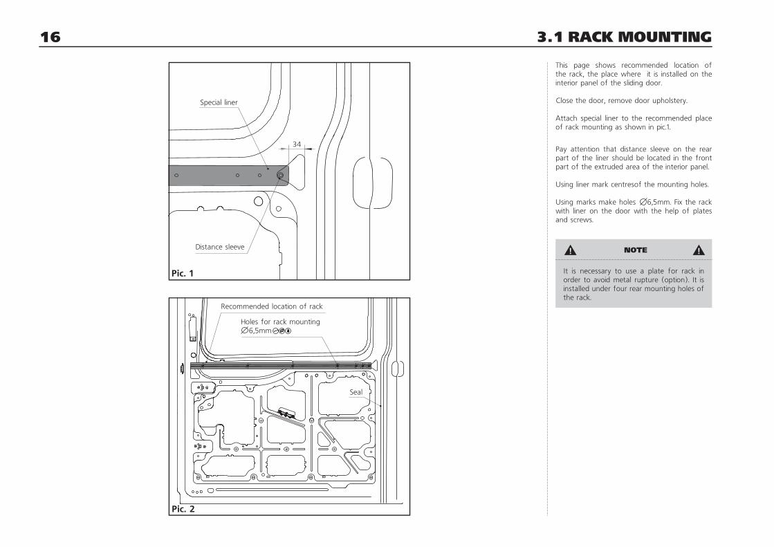
34
Special liner
Distance sleeve
This page shows recommended location of the rack, the place where it is installed on the interior panel of the sliding door.
Close the door, remove door upholstery.
Attach special liner to the recommended place of rack mounting as shown in pic.1.
Pay attention that distance sleeve on the rear part of the liner should be located in the front part of the extruded area of the interior panel.
Using liner mark centresof the mounting holes.
Using marks make holes 6,5mm. Fix the rack with liner on the door with the help of plates and screws.
It is neсessary to use a plate for rack in order to avoid metal rupture (option). It is installed under four rear mounting holes of the rack.
!! NOTE

17
Remove door seal in the place used for cradle mounting (pic. 1).
Attach cradle tightly to pillar. Mark centres of the mounting holes (pic. 2). Pay attention that there is a distance of 7-8mm between cradle plane Б and rack plane A (pic. 3).
Make 2 holes 6,5mm and 6 holes 5mm according to marking (pic. 2).
Use screws M6x25 to fix the cradle at first, then use rivets 4,8x12 (pic. 4).
Make 2 notches on the inner side of the seal to cover distance sleeves of the cradle (pic. 1).
Remount seal (pic. 4).
3.2 CRADLE MOUNTING
Pic. 2
Hole 5mm
Hole 6,5mm
Door seal
Make2 notches
Pic. 1
Pic. 3
À
Á
Screw M6x25
Rivet 4,8x12
Rivet 4,8x12
Pic. 4

18 3.3 PRELIMINARY PREPARATION
Close the door manually.
Make sure that cradle and rod parts do not hinder the door from closing.
Install the rack-and-pinion drive on the rack (pic.2). Attach the rod to the rack-and-pinion drive.
Make two holes 5 mm in the front part of the rack, install a stop here.
Self-tappingscrew 6x11
Stop
Rack
Self-tappingscrew 6x11
Stop
Rack
5 ìì
Pic. 3Pic. 2
Install the rack-and-piniondrive on the rack
Install a rod
Pic. 1
Ðèñ. 1

194.1 THE FIRST CYCLE OF RACK-AND-PINION DRIVE
Clean slots of the rack (pic. 2).
Connect the drive to the controller.
Insert 30A fuse into its connector. The controller gives a long beep.
Start the car engine.
Push control button. The drive will close the door and the controller will be beeping for 1-2 sec. Then start opening. The drive will open the door and reach a stop slowly. Then the drive will start operating in a normal mode.
If you need to diassemble the drive or disconnect the controller, remove 30A fuse from its connector at first.
Pic. 2
Pic. 1
Placeto becleaned
Connector of controllerwiring harness comesto connector of drive wiring harness
Connector of drivewiring harness comes roller wiring harness
Controller wiringharness
!! NOTE

20 4.2 RACK-AND-PINION DRIVE ADJUSTMENT
ROD ADJUSTMENT
The rod position, when the door is normally closed, is shown in the picture 1.
Rotate stud using a hex nut (pic. 2). Adjust rod length for the door to be closed tightly.
When the rod is installed correctly, it should touch a damper on the carriage (pic. 3).
Pic. 3
Damper
Damper
Pic. 1
90° + 5°
Pic. 2
Rod adjustment

214.3 MOUNTING OF DOOR DRIVE COVER AND DECORATIVE FLANGE
1. Fix a drive cover with four self-tapping screws 4,2x13 (pic.1).
2. Insert flange accurately into the rack as it is shown in pictures 2 and 3.
3. Cut off unnecessary part of flange according to the rack (pic. 2 and 3).
Pic. 3
Rack
Flange 2*19 gray
Pic. 1
Self-tapping screws 4,2x13
Drive cover
Clamps forself-tappingscrews
Pic. 2
Insert decorativeflange into rack
Self-tappingscrew 4,2x13
Self-tappingscrew 4,2x13

22 4.4 WARNING STICKER LOCATION
Self-adhesive warning sticker is located outside on the panel of the sliding door. It should be noticeable.
AUTOMATICDOOR
234.5 MOUNTING OF OUTER HANDLE COVER AND INNER HANDLE COVER
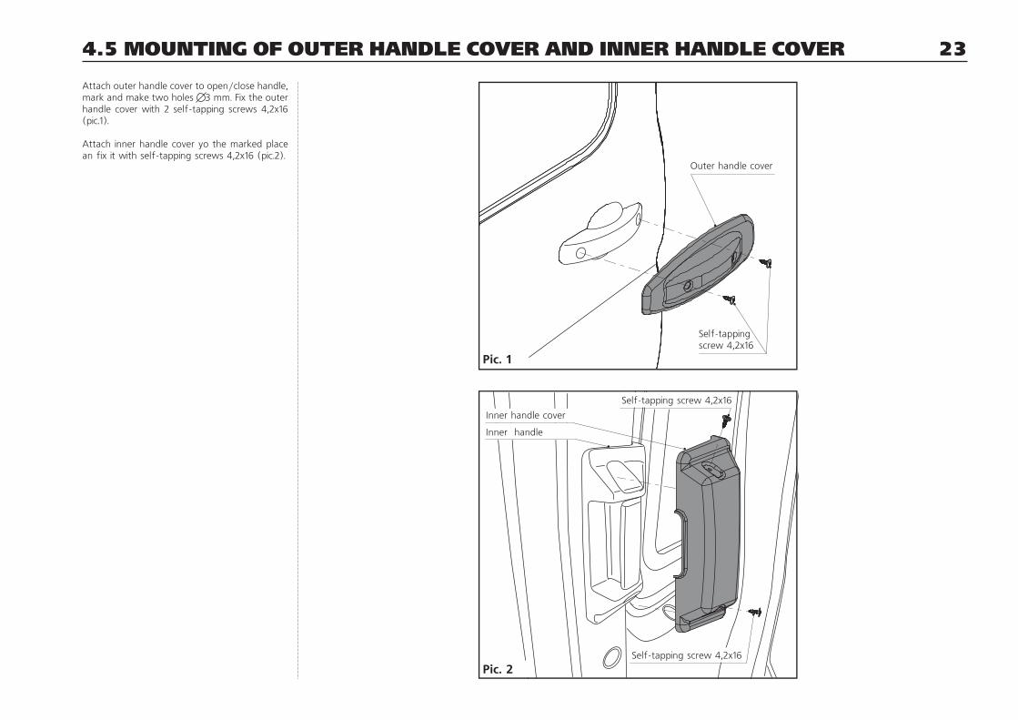
Attach outer handle cover to open/close handle, mark and make two holes 3 mm. Fix the outer handle cover with 2 self-tapping screws 4,2x16 (pic.1).
Attach inner handle cover yo the marked place an fix it with self-tapping screws 4,2x16 (pic.2).
Self-tappingscrew 4,2x16
Outer handle cover
Pic. 2
Pic. 1
Inner handle cover
Inner handle
Self-tapping screw 4,2x16
Self-tapping screw 4,2x16

24
OPENING AND CLOSING
Push and hold control button for~0,5seconds. When you release it, the door starts moving.
STOPPING
Once push the button in order to stop the door while it is moving.
AUTOMATIC ROLLBACK
When encountering an obstruction, the door stops and comes back automatically.
ADJUSTMENT OF OPENING WIDTH
Open the door. Set the required opening width manually. Push and hold control button for~ 10 sec till two beeps. Release control button. Now the drive remembers the set opening width.
OPERATION MODE WITH FIXATION
The drive has two operation modes:
1. with fixation (factory setting) pic.12. without fixation (only with latch actuator) pic.2
To get the mode without fixation push and hold control button for ~ 15 seconds till three long beeps. Release the button.
RETURN TO FACTORY SETTING
Keep and hold control button for ~ 20 seconds till four beeps. Release the control button. All the settings returned to the factory ones.
All the settings return to the factory ones in case when the power is switched off.
4.6 CONTROL AND ADJUSTMENT
MODE WITHOUT FIXATION
Pic. 1
Pic. 2
MODE WITH FIXATION
!! NOTE

25
EMERGENCY OPENING
OUTSIDE (ONLY IN MODE WITHOUT FIXATION):
1. Remove outer cover (pic.1);2. Pull the door handle and hold it (pic.2);3. Pull the rear part of the door towards yourself (pic.3);4. Open the door to the left (pic.2).
INSIDE:
1. Remove inner cover;2. Pull the door handle and hold it;3. Move the drive from ''the dead space'' moving it towards the direction of the bus movement;4. Open the door manually (pic. 3).
4.6 CONTROL AND ADJUSTMENT
2) Pull the door handle and hold it;
4
3
2
3) Pull the rear part of the door towards yourself;4) Open the door to the left.
Pic. 2Pic. 1
1) Remove cover
21 4 3
Pic. 3

26
MANUAL MODE RESET
1. After removing handle covers open the door manually (pic.1, 2).2. Remove a stop (pic.3).3. Remove a drive cover (pic.3).4. Disconnect a connector of the controller wiring harness (pic. 3).5. Unscrew a rod (pic. 4).6. Remove a drive from the rack (pic.4).7. Remove a fuse (30A) from the connector.
The door may be operated in a manual mode if there is a latch actuator.
If there is no latch, standard latch must be restored.
4.6 CONTROL AND ADJUSTMENT
Open the door manually
Pic. 4
Remove a drive from the rack
Pic. 3
Remove a stop
Remove a drive cover
Disconnect a connectorof the controller wiring harness
Remove outer handle
Pic. 1 Pic. 2
Removeinner handle
Unscrew a rod

16 CONTACTSDEARCUSTOMER!ifyouhaveanyquestionsconcerningguaranteemaintenanceandpost-guaranteemaintenance,pleasecontactusat:RegisteredOffice:61,Borkovskayastr.,Toliatty,Russia,445043POSTALADDRESS:P.O.Box1982,26,MarshalZhukovStr.,Toliatty,Russia,445051http://www.ador.suPhonenumber:+78482202050(08.00-18.00Moscowtime)
SERVICEDEPARTMENTServicedepartment (8482)20-20-50(ext.123)(8482)55-15-50
SALESDEPARTMENTAdorUSA
Raleigh,NCUSAhttp://www.AdorUSA.com
(216)214-0828 [email protected]