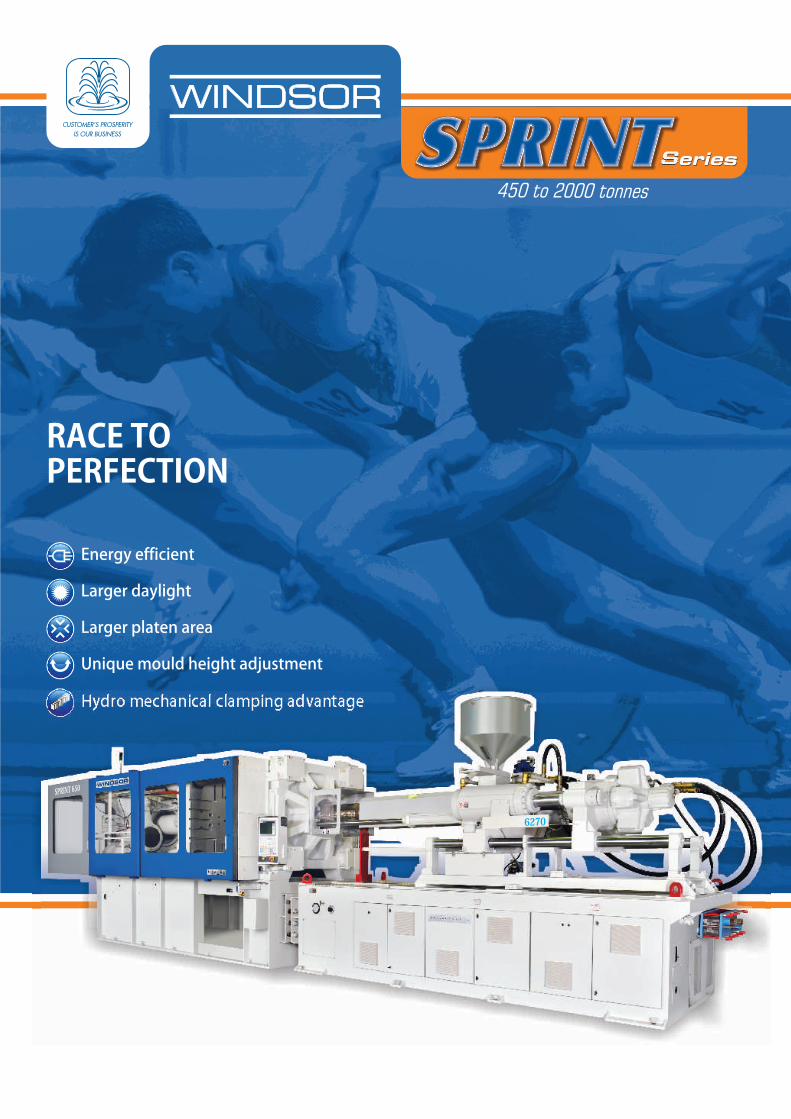
RACE TO PERFECTION
12
Series S r es ei 450 to 0 s 200 tonne Energy efficient Larger daylight Larger platen area Unique mould height adjustment Hydro mechanical clamping advantage RACE TO PERFECTION
Transcript of RACE TO PERFECTION
SeriesS r ese i
450 to 0 s200 tonne
Energy efficient
Larger daylight
Larger platen area
Unique mould height adjustment
Hydro mechanical clamping advantage
RACE TOPERFECTION
“4-Top Concepts for Sprint Series"
1. Productivity and Versatility- Fast platen movement- High plasticizing rates- Wide platen and bigger daylight- High injection speed - Better Mold Opening Stroke
2. Savings- Less hydraulic oil requirement- Low power consumption (up to 35%)- Less floor space requirement (25% reduction)- Low maintenance cost
3. Easy Operation and Precision- User friendly & intelligent controller- Precise and repetitive performance
4. Reliability for Man, Mould & Machine- Platen design by Finite Element Analysis (FEA)- Hydraulic & Electrically interlocked safety features.- International best sourcing of components.
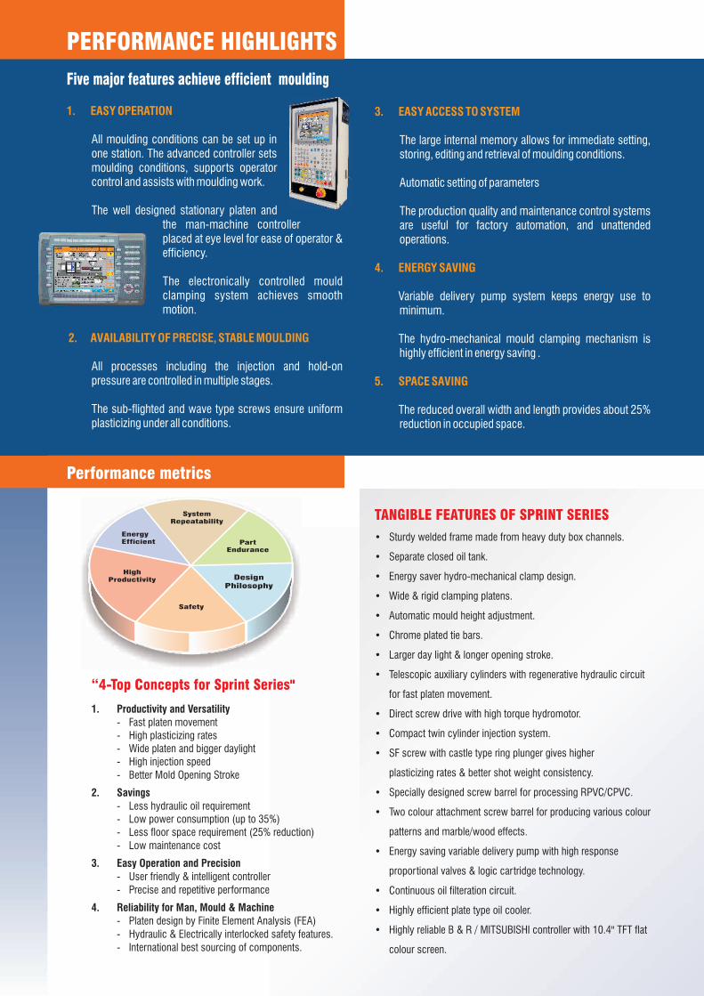
SystemRepeatability
Energy Efficient
High Productivity
Safety
Part Endurance
Design Philosophy
TANGIBLE FEATURES OF SPRINT SERIES
• Sturdy welded frame made from heavy duty box channels.
• Separate closed oil tank.
• Energy saver hydro-mechanical clamp design.
• Wide & rigid clamping platens.
• Automatic mould height adjustment.
• Chrome plated tie bars.
• Larger day light & longer opening stroke.
• Telescopic auxiliary cylinders with regenerative hydraulic circuit
for fast platen movement.
• Direct screw drive with high torque hydromotor.
• Compact twin cylinder injection system.
• SF screw with castle type ring plunger gives higher
plasticizing rates & better shot weight consistency.
• Specially designed screw barrel for processing RPVC/CPVC.
• Two colour attachment screw barrel for producing various colour
patterns and marble/wood effects.
• Energy saving variable delivery pump with high response
proportional valves & logic cartridge technology.
• Continuous oil filteration circuit.
• Highly efficient plate type oil cooler.
• Highly reliable B & R / MITSUBISHI controller with 10.4" TFT flat
colour screen.
3. EASY ACCESS TO SYSTEM
4. ENERGY SAVING
5. SPACE SAVING
The large internal memory allows for immediate setting, storing, editing and retrieval of moulding conditions.
Automatic setting of parameters
The production quality and maintenance control systems are useful for factory automation, and unattended operations.
Variable delivery pump system keeps energy use to minimum.
The hydro-mechanical mould clamping mechanism is highly efficient in energy saving .
The reduced overall width and length provides about 25% reduction in occupied space.
1. EASY OPERATION
2. AVAILABILITY OF PRECISE, STABLE MOULDING
All moulding conditions can be set up in one station. The advanced controller sets moulding conditions, supports operator control and assists with moulding work.
The well designed stationary platen and the man-machine controller placed at eye level for ease of operator & efficiency.
The electronically controlled mould clamping system achieves smooth motion.
All processes including the injection and hold-on pressure are controlled in multiple stages.
The sub-flighted and wave type screws ensure uniform plasticizing under all conditions.
Five major features achieve efficient moulding
Performance metrics
PERFORMANCE HIGHLIGHTS
1 . Fast & Precise Mould Closing and opening System
2. Highly rigid Mould clamping
Robust and fast acting telescopic twin auxiliary cylinders constructed with friction free seals and use of regenerative hydraulics circuit, backed by electronically controlled high response proportional valves and logic cartridge technology ensures fast , smooth and precise mould closing and opening system
Design of platens and tie bars based on deformation analysis using Finite Element Analysis ensures High rigidity even at higher injection rate minimized stresses on mould platens and provides better moulding stability resulting in longer mould’s and machine’s service life.
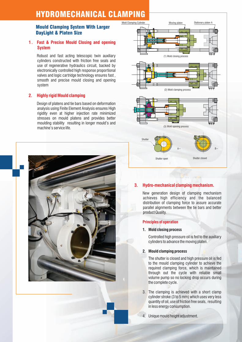
HYDROMECHANICAL CLAMPING
Mould Clamping System With LargerDayLight & Platen Size
3. Hydro-mechanical clamping mechanism.
Principles of operation
New generation design of clamping mechanism achieves high efficiency and the balanced distribution of clamping force to assure accurate parallel alignments between the tie bars and better product Quality.
1. Mold closing process
Controlled high pressure oil is fed to the auxiliary cylinders to advance the moving platen.
2. Mould clamping process
The shutter is closed and high pressure oil is fed to the mould clamping cylinder to achieve the required clamping force, which is maintained through out the cycle with reliable small volume pump so no locking drop occurs during the complete cycle.
3. The clamping is achieved with a short clamp cylinder stroke (3 to 5 mm) which uses very less quantity of oil, use of friction free seals, resulting in less energy consumption.
4. Unique mould height adjustment.
(3) Mold opening process
Shutter closed
B~
Shutter open
A~
Shutter
(2) Mold clamping process
Mold Clamping Cylinder Stationary platen AMoving platen
(1) Mold closing process

1. Precise & Stable moulding
2. Temperature Control
Achieved through precise setting on fast response controller and proportional valves with variable delivery pump.
PID temperature control with auto tuning facility for barrel and nozzle temperature settings provide faster response to temperature fluctuations as well as environmental changes and thus improves moulding stability, while saving electrical energy used for barrel heating.
3. Smooth velocity to pressure changeover
4. Standby temperature
Effectively prevents flash and gives stability and repeatability in moulding condition .
The standby temperature is standardized to prevent burning of materials and to save time for restart for new mould
5. Oil Temperature Control
The 100% oil is continuously cooled and filtered through an auxiliary circuit of pump with plate type heat exchanger and filter.
6. Three-direction take out of products
Large space and access from three directions enables to remove large mouldings which drop easily.
7. SF screw
The SF screw is a high-kneading screw with the following features:
1. Processability at lower melt temperature, shortens moulding cycle time and reduces energy consumption
2. Better melt homogeneity hence eliminates moulding defects such as weld marks, flow marks and silver streaks.
3. Reduces master batch consumption.4. High plasticizing rates increases productivity .5. Shot weight consistency through specially designed
castle type ring plunger.
Sub Flight Main Flight
Sub Flight accelerates separation of solid
and melt of the resin in metering process
Sub Flight helps shear efficiency in the space
between cylinder and sub flight when
resin overflows sub flight
Main Flight
Sub Flight
Optimum plasticizing that giveshigh quality mouldings
HIGH QUALITY MOULDING
Setting CZone 5 / Zone 4 / Zone2 / Zone1
Setting CZone 5 / Zone 4 / Zone2 / Zone1

Energy Saving
Use of variable delivery pump system keeps energy consumption to a minimum. The flow rate and pressure necessary for each process of moulding cycle are kept under precise control to lower energy loss in the system.The hydro-mechanical mould clamping mechanism is also a very efficient energy saver
Advanced hydraulics and control give moulding stability and precisionwhile saving energy
HIGH EFFICIENCY & ENERGY EFFICIENT
Power loss
50
100
150
200
25 50 75 100
Op
erat
ing
pre
ssu
re p
(bar
)
Flow qv (L/min)
Only 4.2 kw from the drive motor,which has a power of 33.4 kw is required to lift the load the rest,
Uti
lised
po
wer
actu
ato
r
Energy Balance
29.4 kw is wasted
50
100
150
200
25 50 75 100
Op
erat
ing
pre
ssu
re p
(bar
)
Flow qv (L/min)
With the same power requirement for lifting the
load,as in example 1 (4.2 kw),here appox.
Uti
lised
po
wer
actu
ato
r
Energy Balance
15.8 kw is converted into heat.
50
100
150
200
25 50 75 100
Op
erat
ing
pre
ssu
re p
(bar
)
Flow qv (L/min)
In this case only the losses are, therefore, minimised
with SPRINT
Uti
lised
po
wer
actu
ato
r
Energy Balance
Power loss
Powerloss
0.8 kw is convertd into 0.8 kw
In built control / PLC panel reduces connectivity
Intelligent MMI with wide viewing angle LCD
MCCB as machine power switch
Short circuit protected SSRs for heater circuit
Control System
1. 10.4" TFT colour flat screens with multifunctions for
operation and display.
2. High resolution precision setting.
3. Machine cycle timing details in a single screen.
4. Hourly & monthly production monitoring system with
cumulative production counters.
5. On line editing of process parameters.
6. Statistical process control of 15 nos. various critical
parameters for last 100 machine cycles.
7. Ethernet inter face port.
8. Access protection via four level password system.
9. Events protocol (logbook) for more than 1000 events
with help menu & facility of copy to external drive.
10. Parts Counter with good / bad parts evaluation.
Superior controlswith Leading edge diagnostic functions.
11. Automatic functions for
mould height adjustment,
lubrication, purging, barrel
heating, auto tuning temp.
control.
12. Trend diagnosis of various parameters.
13. Analog input / output monitoring in millivolts.
14. Graphical display with history of selected functions for last 5 curves.
15. 5 modes for error diagnosis.
16. Maintenance schedules on
screen.
17. Analog / digital output force
facility for easy diagnosis.
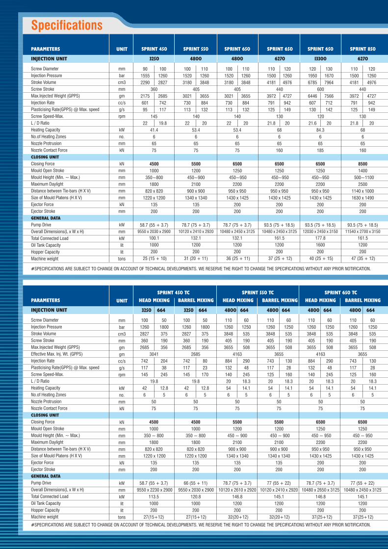
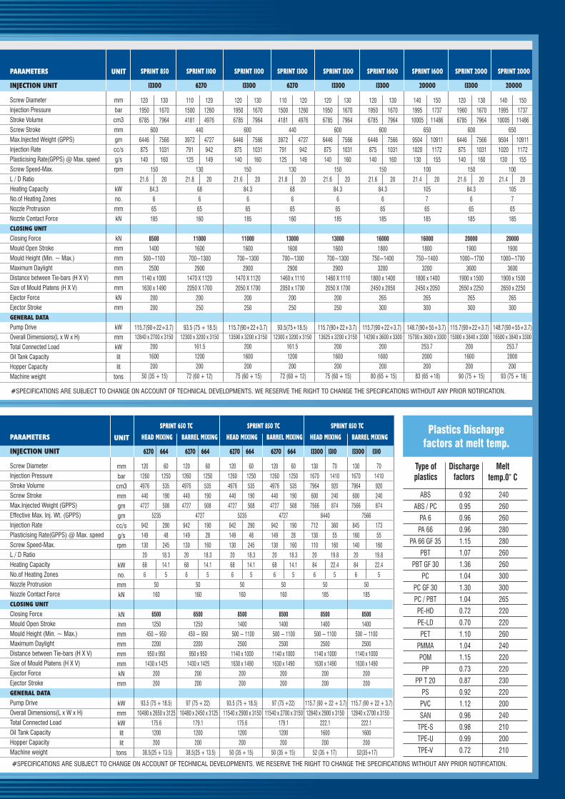
PARAMETERS
INJECTION UNIT
Screw Diameter
Injection Pressure
Stroke Volume
Screw Stroke
Max.Injected Weight (GPPS)
Effective Max. Inj. Wt. (GPPS)
Injection Rate
Plasticising Rate(GPPS) @ Max. speed
Screw Speed-Max.
L / D Ratio
Heating Capacity
No.of Heating Zones
Nozzle Protrusion
Nozzle Contact Force
CLOSING UNIT
Closing Force
Mould Open Stroke
Mould Height (Min. ~ Max.)
Maximum Daylight
Distance between Tie-bars (H X V)
Size of Mould Platens (H X V)
Ejector Force
Ejector Stroke
GENERAL DATA
Pump Drive
Overall Dimensions(L x W x H)
Total Connected Load
Oil Tank Capacity
Hopper Capacity
Machine weight
#SPECIFICATIONS ARE SUBJECT TO CHANGE ON ACCOUNT OF TECHNICAL DEVELOPMENTS. WE RESERVE THE RIGHT TO CHANGE THE SPECIFICATIONS WITHOUT ANY PRIOR NOTIFICATION.
SPRINT 450 TC SPRINT 550 TC SPRINT 650 TC SPRINT 650 TC SPRINT 850 TC SPRINT 850 TC
HEAD MIXING BARREL MIXING HEAD MIXING BARREL MIXING HEAD MIXING BARREL MIXING HEAD MIXING BARREL MIXING HEAD MIXING BARREL MIXING HEAD MIXING BARREL MIXING
Specifications
PARAMETERS
INJECTION UNIT
Screw Diameter
Injection Pressure
Stroke Volume
Screw Stroke
Max.Injected Weight (GPPS)
Injection Rate
Plasticising Rate(GPPS) @ Max. speed
Screw Speed-Max.
L / D Ratio
Heating Capacity
No.of Heating Zones
Nozzle Protrusion
Nozzle Contact Force
CLOSING UNIT
Closing Force
Mould Open Stroke
Mould Height (Min. ~ Max.)
Maximum Daylight
Distance between Tie-bars (H X V)
Size of Mould Platens (H X V)
Ejector Force
Ejector Stroke
GENERAL DATA
Pump Drive
Overall Dimensions(L x W x H)
Total Connected Load
Oil Tank Capacity
Hopper Capacity
Machine weight
90 100 100 110 100 110 110 120 120 130 110 120 120 130 110 120 120 130 110 120 120 130 120 130 140 150 120 130 140 150
1555 1260 1520 1260 1520 1260 1500 1260 1950 1670 1500 1260 1950 1670 1500 1260 1950 1670 1500 1260 1950 1670 1950 1670 1995 1737 1960 1670 1995 1737
2290 2827 3180 3848 3180 3848 4181 4976 6785 7964 4181 4976 6785 7964 4181 4976 6785 7964 4181 4976 6785 7964 6785 7964 10005 11486 6785 7964 10005 11486
360 405 405 440 600 440 600 440 600 440 600 600 650 600 650
2175 2685 3021 3655 3021 3655 3972 4727 6446 7566 3972 4727 6446 7566 3972 4727 6446 7566 3972 4727 6446 7566 6446 7566 9504 10911 6446 7566 9504 10911
601 742 730 884 730 884 791 942 607 712 791 942 875 1031 791 942 875 1031 791 942 875 1031 875 1031 1020 1172 875 1031 1020 1172
95 117 113 132 113 132 125 149 130 142 125 149 140 160 125 149 140 160 125 149 140 160 140 160 130 155 140 160 130 155
145 140 140 130 120 130 150 130 150 130 150 150 100 150 100
22 19.8 22 20 22 20 21.8 20 21.6 20 21.8 20 21.6 20 21.8 20 21.6 20 21.8 20 21.6 20 21.6 20 21.4 20 21.6 20 21.4 20
41.4 53.4 53.4 68 84.3 68 84.3 68 84.3 68 84.3 84.3 105 84.3 105
6 6 6 6 6 6 6 6 6 6 6 6 7 6 7
65 65 65 65 65 65 65 65 65 65 65 65 65 65 65
75 75 75 160 185 160 185 160 185 160 185 185 185 185 185
4500 5500 6500 6500 6500 8500 8500 11000 11000 13000 13000 16000 16000 20000 20000
1000 1200 1250 1250 1250 1400 1400 1600 1600 1600 1600 1800 1800 1900 1900
350~800 450~900 450~950 450~950 450~950 500~1100 500~1100 700~1300 700~1300 700~1300 700~1300 750~1400 750~1400 1000~1700 1000~1700
1800 2100 2200 2200 2200 2500 2500 2900 2900 2900 2900 3200 3200 3600 3600
820 x 820 900 x 900 950 x 950 950 x 950 950 x 950 1140 x 1000 1140 x 1000 1470 X 1120 1470 X 1120 1460 x 1110 1460 X 1110 1800 x 1400 1800 x 1400 1900 x 1500 1900 x 1500
1220 x 1200 1340 x 1340 1430 x 1425 1430 x 1425 1430 x 1425 1630 x 1490 1630 x 1490 2050 X 1700 2050 X 1700 2050 x 1700 2050 X 1700 2450 x 2050 2450 x 2050 2650 x 2250 2650 x 2250
135 135 200 200 200 200 200 200 200 200 200 265 265 265 265
200 200 200 200 200 200 200 250 250 250 250 300 300 300 300
58.7 (55 + 3.7) 78.7 (75 + 3.7) 78.7 (75 + 3.7) 93.5 (75 + 18.5) 93.5 (75 + 18.5) 93.5 (75 + 18.5) 115.7(90+22+3.7) 93.5 (75 + 18.5) 115.7(90+22+3.7) 93.5(75+18.5) 115.7(90+22+3.7) 115.7(90+22+3.7) 148.7(90+55+3.7) 115.7(90+22+3.7) 148.7(90+55+3.7)
9550 x 2030 x 2900 10120 x 2410 x 2920 10480 x 2450 x 3125 10480 x 2450 x 3125 12030 x 2450 x 3150 11540 x 2700 x 3150 12840 x 2700 x 3150 12300 x 3200 x 3150 13590 x 3200 x 3150 12300 x 3200 x 3150 13625 x 3200 x 3150 14290 x 3600 x 3300 15790 x 3600 x 3300 15000 x 3840 x 3300 16500 x 3840 x 3300
100.1 132.1 132.1 161.5 177.8 161.5 200 161.5 200 161.5 200 200 253.7 200 253.7
1000 1200 1200 1200 1600 1200 1600 1200 1600 1200 1600 1600 2000 1600 2000
200 200 200 200 200 200 200 200 200 200 200 200 200 200 200
25 (15 + 10) 31 (20 + 11) 36 (25 + 11) 37 (25 + 12) 40 (25 + 15) 47 (35 + 12) 50 (35 + 15) 72 (60 + 12) 75 (60 + 15) 72 (60 + 12) 75 (60 + 15) 80 (65 + 15) 83 (65 +18) 90 (75 + 15) 93 (75 + 18)
#SPECIFICATIONS ARE SUBJECT TO CHANGE ON ACCOUNT OF TECHNICAL DEVELOPMENTS. WE RESERVE THE RIGHT TO CHANGE THE SPECIFICATIONS WITHOUT ANY PRIOR NOTIFICATION.
SPRINT 450 SPRINT 550 SPRINT 650 SPRINT 650 SPRINT 650 SPRINT 850 SPRINT 850 SPRINT 1100 SPRINT 1100 SPRINT 1300 SPRINT 1300 SPRINT 1600 SPRINT 1600 SPRINT 2000 SPRINT 2000
3250 4800 4800 6270 13300 6270 13300 6270 13300 6270 13300 13300 20000 13300 20000
UNIT
mm
bar
cm3
mm
gm
cc/s
g/s
rpm
kW
no.
mm
kN
kN
mm
mm
mm
mm
mm
kN
mm
kW
mm
kW
lit
lit
tons
UNIT
mm
bar
cm3
mm
gm
gm
cc/s
g/s
rpm
kW
no.
mm
kN
kN
mm
mm
mm
mm
mm
kN
mm
kW
mm
kW
lit
lit
tons
100 50 100 50 110 60 110 60 110 60 110 60 120 60 120 60 120 60 120 60 130 70 130 70
1260 1800 1260 1800 1260 1250 1260 1250 1260 1250 1260 1250 1260 1250 1260 1250 1260 1250 1260 1250 1670 1410 1670 1410
2827 375 2827 375 3848 535 3848 535 3848 535 3848 535 4976 535 4976 535 4976 535 4976 535 7964 920 7964 920
360 190 360 190 405 190 405 190 405 190 405 190 440 190 440 190 440 190 440 190 600 240 600 240
2685 356 2685 356 3655 508 3655 508 3655 508 3655 508 4727 508 4727 508 4727 508 4727 508 7566 874 7566 874
3041 2685 4163 3655 4163 3655 5235 4727 5235 4727 8440 7566
742 204 742 80 884 290 743 130 884 290 743 130 942 290 942 190 942 290 942 190 712 360 845 173
117 38 117 23 132 48 117 28 132 48 117 28 149 48 149 28 149 48 149 28 130 55 160 55
145 245 145 170 140 245 125 160 140 245 125 160 130 245 130 160 130 245 130 160 110 160 140 160
19.8 19.8 20 18.3 20 18.3 20 18.3 20 18.3 20 18.3 20 18.3 20 18.3 20 18.3 20 19.8 20 19.8
42 12.8 42 12.8 54 14.1 54 14.1 54 14.1 54 14.1 68 14.1 68 14.1 68 14.1 68 14.1 84 22.4 84 22.4
6 5 6 5 6 5 6 5 6 5 6 5 6 5 6 5 6 5 6 5 6 5 6 5
50 50 50 50 50 50 50 50 50 50 50 50
75 75 75 75 75 75 160 160 160 160 185 185
4500 4500 5500 5500 6500 6500 6500 6500 8500 8500 8500 8500
1000 1000 1200 1200 1250 1250 1250 1250 1400 1400 1400 1400
350 ~ 800 350 ~ 800 450 ~ 900 450 ~ 900 450 ~ 950 450 ~ 950 450 ~ 950 450 ~ 950 500 ~ 1100 500 ~ 1100 500 ~ 1100 500 ~ 1100
1800 1800 2100 2100 2200 2200 2200 2200 2500 2500 2500 2500
820 x 820 820 x 820 900 x 900 900 x 900 950 x 950 950 x 950 950 x 950 950 x 950 1140 x 1000 1140 x 1000 1140 x 1000 1140 x 1000
1220 x 1200 1220 x 1200 1340 x 1340 1340 x 1340 1430 x 1425 1430 x 1425 1430 x 1425 1430 x 1425 1630 x 1490 1630 x 1490 1630 x 1490 1630 x 1490
135 135 135 135 200 200 200 200 200 200 200 200
200 200 200 200 200 200 200 200 200 200 200 200
58.7 (55 + 3.7) 66 (55 + 11) 78.7 (75 + 3.7) 77 (55 + 22) 78.7 (75 + 3.7) 77 (55 + 22) 93.5 (75 + 18.5) 97 (75 + 22) 93.5 (75 + 18.5) 97 (75 +22) 115.7 (90 + 22 + 3.7) 115.7 (90 + 22 + 3.7)
9550 x 2230 x 2900 9550 x 2030 x 2900 10120 x 2610 x 2920 10120 x 2410 x 2920 10480 x 2650 x 3125 10480 x 2450 x 3125 10480 x 2650 x 3125 10480 x 2450 x 3125 11540 x 2900 x 3150 11540 x 2700 x 3150 12840 x 2900 x 3150 12840 x 2700 x 3150
113.5 120.8 146.8 145.1 146.8 145.1 175.6 179.1 175.6 179.1 222.1 222.1
1000 1000 1200 1200 1200 1200 1200 1200 1200 1200 1600 1600
200 200 200 200 200 200 200 200 200 200 200 200
27(15+12) 27(15+12) 32(20+12) 32(20+12) 37(25+12) 37(25+12) 38.5(25 + 13.5) 38.5(25 + 13.5) 50 (35 + 15) 50 (35 + 15) 52 (35 + 17) 52(35+17)
3250 664 3250 664 4800 664 4800 664 4800 664 4800 664 6270 664 6270 664 6270 664 6270 664 13300 1310 13300 1310
#SPECIFICATIONS ARE SUBJECT TO CHANGE ON ACCOUNT OF TECHNICAL DEVELOPMENTS. WE RESERVE THE RIGHT TO CHANGE THE SPECIFICATIONS WITHOUT ANY PRIOR NOTIFICATION.
#SPECIFICATIONS ARE SUBJECT TO CHANGE ON ACCOUNT OF TECHNICAL DEVELOPMENTS. WE RESERVE THE RIGHT TO CHANGE THE SPECIFICATIONS WITHOUT ANY PRIOR NOTIFICATION.
Dischargefactors
Melttemp.0° C

MACHINE MODEL :
PARAMETER
INJECTION UNIT
Screw Diameter
Injection Pressure
Stroke Volume
Screw Stroke
Max.Injected Weight *
Injection Rate
Plasticising Rate @ Max. speed **
Screw Speed-Max.
L / D Ratio
Heating Capacity
No.of Heating Zones
Nozzle Protrusion
Nozzle Contact Force
CLOSING UNIT
Closing Force
Mould Open Stroke
Mould Height (Min. ~ Max.)
Maximum Daylight
Distance between Tie-bars (H X V)
Size of Mould Platens (H X V)
Ejector Force
Ejector Stroke
GENERAL DATA
Pump Drive
Overall Dimensions(L x W x H)
Total Connected Load
Oil Tank Capacity
Hopper Capacity
Machine weight
100 100 110 110 120 120
1260 1260 1260 1260 1260 1260
2827 2827 3848 3848 4976 4976
360 360 405 405 440 440
3223 3223 4386 4386 5672 5672
403 403 565 565 565 565
78 78 82 82 84 84
70 70 70 70 65 65
19.8 19.8 20 20 20 20
41.4 41.4 53.4 53.4 68 68
6 6 6 6 6 6
50 50 50 50 50 50
75 75 75 75 160 160
4500 5500 5500 6500 6500 8500
1000 1200 1200 1250 1250 1400
350 ~ 800 450 ~ 900 450 ~ 900 450 ~ 950 450 ~ 950 500 ~ 1100
1800 2100 2100 2200 2200 2500
820 x 820 900 x 900 900 x 900 950 x 950 950 x 950 1140 x 1000
1220 x 1200 1340 x 1340 1340 x 1340 1430 x 1425 1430 x 1425 1590 x 1470
135 135 135 200 200 200
200 200 200 200 200 200
58.7(55+3.7) 58.7(55+3.7) 78.7(75+3.7) 78.7(75+3.7) 93.5(75+18.5) 93.5(75+18.5)
9550 x 2030 x 2900 9830 x 2410 x 2900 10120 x 2410 x 2920 10480 x 2450 x 3125 10480 x 2450 x 3125 11540 x 2700 x 3150
100.1 100.1 132.1 132.1 161.5 161.5
1000 1000 1200 1200 1200 1200
200 200 200 200 200 200
25 (15 + 10) 30(20+10) 31(20+11) 36 (25 + 11) 37 (25 + 12) 47 (35 + 12)
SPRINT 450 R SPRINT 550 R SPRINT 550 R SPRINT 650 R SPRINT 650 R SPRINT 850 R
3250 3250 4800 4800 6270 6270
UNIT
mm
bar
cm3
mm
gm
cc/s
g/s
rpm
kW
no.
mm
kN
kN
mm
mm
mm
mm
mm
kN
mm
kW
mm
kW
lit
lit
tons
Specifications
SPECIFICATIONS ARE SUBJECT TO CHANGE ON ACCOUNT OF TECHNICAL DEVELOPMENTS. WE RESERVE THE RIGHT TO CHANGE THE SPECIFICATIONS WITHOUT ANY PRIOR NOTIFICATION.
* Shot weight will vary as per the formulation density** Permissible RPM is a function of formulation and hence depending on the RPM permitted by formulation, plasticising capacity will vary.
>
> Process optimisation at your plant if required.
Customized machines to suit your applications.
at your service
Our Application engineering team provides youA to Z about the Project, which includes the following.
APPLICATIONS
SPRINT SERIES MACHINES ARE SUITABLE FOR A WIDE VARIETY OF APPLICATIONS SUCH AS
>
>INDUSTRIAL MOULDINGS.
>WHITE GOODS & APPLIANCES.
>CRATES & PACKAGING.
>PAILS & CONTAINERS.
>RPVC/ CPVC FITTINGS AND
IRRIGATION.
>HOUSEHOLD & FURNITURE.
AUTOMOBILES.

Automatic purging function
Suck back function (Before& After plasticization)
Wide selection of special application screw & barrels
Hopper sliding unit.
Injection unit swiveling facility.(manual)
Inbuilt barrel temperature PID control
Ceramic heater bands
Barrel heater safety cover
Auto-start barrel heating function
Nozzle centering allignment device.
Screw speed Indication on MMI
Short circuit proof SSR control circuit for heater bands
High quality energy saving variable delivery pump
High response BOSCH REXROTH proportional pressure/ flow valves.
Seperate oil circulation circuit for cooling and filtering.
Reduced power consumption
The Friction-free seals to provide no stick-sleep and the high response
effects during the high pressure/speed motions as well as assuring the
long service life.
Automatic pump selection for energy saving.
Solenoid valves with LED Indication
Low-noise hydraulic control system
Return line oil filter with clogging alarm signal
Oil temperature limit Alarm
Oil Level guage with low level alarm
Plate type oil cooler(Highly efficient & Easy maintenance)
Oil tank air breathers with filters.
Provision to isolate oil tank for maintenance
Efficient piping by using max. no. of hoses thus achieved zero oil leakage.
Easy maintenance
New generation highly reliable B & R / Mitsubishi controller.
Operator friendly screens with direct access.
10.4"TFT colour flat screen with multifunctions for operations and display.
Soft keys to select various machine functions.
Reliable identical hardware modules.
System can be flexibly expanded with modules.
Mould data Storage.60 sets of internal mold memory plus expandable with
external memory storage device.
Indication of actual operating values.
Fast call up for screen pages.
Running function display by LED on function keys & status message on
MMI.
On line editing of process parameters
Control hardware health indication on screen
Machine cycle timing details in a single screen.
Temperature setting resolution in 1 degree centigrade.
Time setting resolution in 0.01 sec.
Hourly & monthly production monitoring system with cumulative
production counters.
HYDRAULICS
SPRINT MACHINE FEATURES
Hydro-mechanical mould clamping.
Robust & fast acting 02 no.auxillary cylinders with regenerative hyd. circuit
for fast platen movement.
Shorter tonnage buildup time due to less oil requirement.
Larger daylight - very useful for producing deep drawn articles.
Large mould platen area for producing large article
Platen casting designed with finite element analysis for maximum rigidity.
Mould plates with 'T' slots.
Electrical and hydraulic safety interlocks in mould platen movements for
mould & operator safety.
Low pressure & speed mould protection device.
Partial decompression facility.
5-Stage mould close/4-Stage mould open pressure & speed control.
2-Stage, multi Function hydraulic Ejection control.
Set mode for mould mounting(Low speed & pressure mould open/close
function.)
Wear-resistant supporting tracks for moveable platen.
Automatic lubrication system by central lubrication device.
Adjustable moving platen support for running heavy moulds.
Auto mould height adjustment.
No requirement of ram spacer change for mould height adjustment thus
drastacally reduced mould change time.
Ejection parallel to mould opening (Without speed/pressure setting on
MMI)
Chrome plated tiebar for reliable endurance.
Core pull parallel to mould opening (Without speed/pressure setting on
MMI)
Stroke sensor for mould open/close and ejection
Graphite impregnated oilless bushes used to reduce wear & tear of
clamping mechanism.
Safety doors with clear PMMA windows
Low dry cycle time
Less floor space requirement.
Twin cylinder balanced injection system.
Twin cylinder Injection unit control.
Nitrided screw- barrel provided for the hardness to enhance the wear-
resistance and long life characteristic.
Sub-flighted screw for better melt quality and low temperature
plasticisation.
Castle type ring plunger for better shot weight accuracy.
10 stage injection pressure/speed/position control.(Selectable 5 to 10).
5 stage holding phase pressure/speed/time control.(Selectable 3 to 5).
3 stage plasticizing pressure/ speed / position control.
Injection to holdon switchover on time & position control.
Flow moulding facility for thick parts of higher weights.
Stroke sensor for injection.
Plasticizing cold start prevention function.
Purge cover with electrical interlock.
Well supported barrel for nozzle allignment
Injection Unit anti-slip aluminium chequer plate.
Clamping unit
Injection Unit
CONTROL SYSTEM
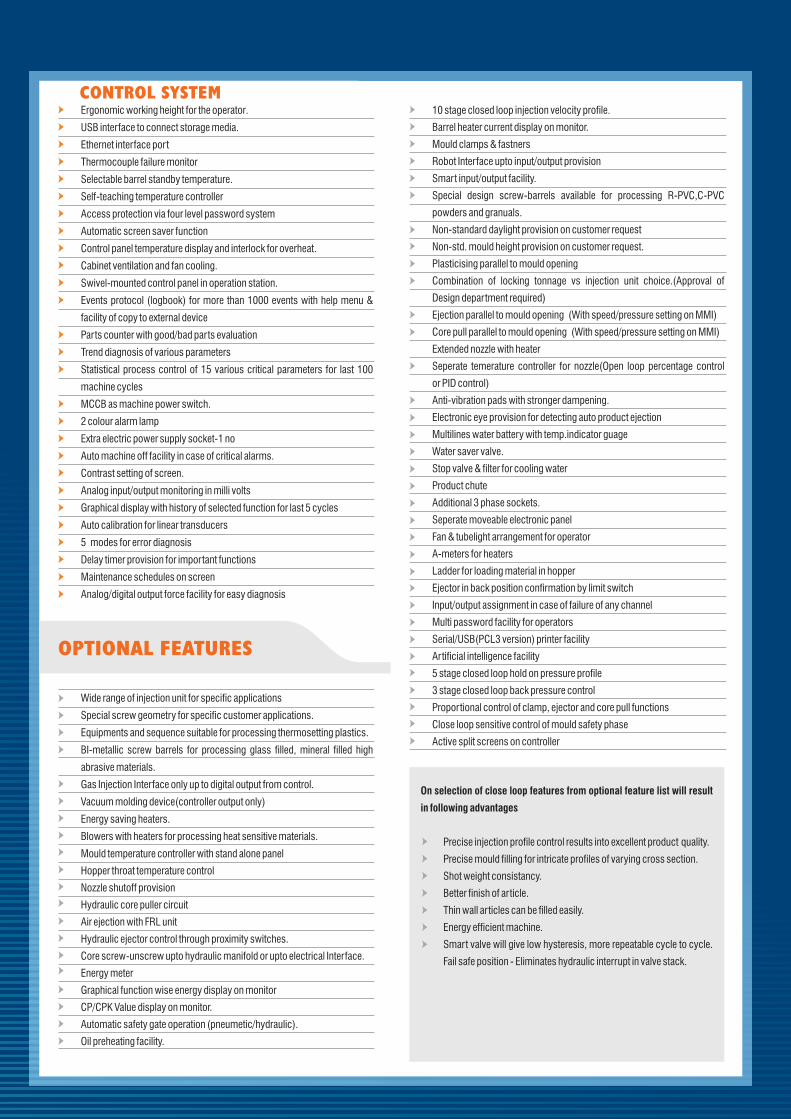
Ergonomic working height for the operator.
USB interface to connect storage media.
Ethernet interface port
Thermocouple failure monitor
Selectable barrel standby temperature.
Self-teaching temperature controller
Access protection via four level password system
Automatic screen saver function
Control panel temperature display and interlock for overheat.
Cabinet ventilation and fan cooling.
Swivel-mounted control panel in operation station.
Events protocol (logbook) for more than 1000 events with help menu &
facility of copy to external device
Parts counter with good/bad parts evaluation
Trend diagnosis of various parameters
Statistical process control of 15 various critical parameters for last 100
machine cycles
MCCB as machine power switch.
2 colour alarm lamp
Extra electric power supply socket-1 no
Auto machine off facility in case of critical alarms.
Contrast setting of screen.
Analog input/output monitoring in milli volts
Graphical display with history of selected function for last 5 cycles
Auto calibration for linear transducers
5 modes for error diagnosis
Delay timer provision for important functions
Maintenance schedules on screen
Analog/digital output force facility for easy diagnosis
Wide range of injection unit for specific applications
Special screw geometry for specific customer applications.
Equipments and sequence suitable for processing thermosetting plastics.
BI-metallic screw barrels for processing glass filled, mineral filled high
abrasive materials.
Gas Injection Interface only up to digital output from control.
Vacuum molding device(controller output only)
Energy saving heaters.
Blowers with heaters for processing heat sensitive materials.
Mould temperature controller with stand alone panel
Hopper throat temperature control
Nozzle shutoff provision
Hydraulic core puller circuit
Air ejection with FRL unit
Hydraulic ejector control through proximity switches.
Core screw-unscrew upto hydraulic manifold or upto electrical Interface.
Energy meter
Graphical function wise energy display on monitor
CP/CPK Value display on monitor.
Automatic safety gate operation (pneumetic/hydraulic).
Oil preheating facility.
OPTIONAL FEATURES
10 stage closed loop injection velocity profile.
Barrel heater current display on monitor.
Mould clamps & fastners
Robot Interface upto input/output provision
Smart input/output facility.
Special design screw-barrels available for processing R-PVC,C-PVC
powders and granuals.
Non-standard daylight provision on customer request
Non-std. mould height provision on customer request.
Plasticising parallel to mould opening
Combination of locking tonnage vs injection unit choice.(Approval of
Design department required)
Ejection parallel to mould opening (With speed/pressure setting on MMI)
Core pull parallel to mould opening (With speed/pressure setting on MMI)
Extended nozzle with heater
Seperate temerature controller for nozzle(Open loop percentage control
or PID control)
Anti-vibration pads with stronger dampening.
Electronic eye provision for detecting auto product ejection
Multilines water battery with temp.indicator guage
Water saver valve.
Stop valve & filter for cooling water
Product chute
Additional 3 phase sockets.
Seperate moveable electronic panel
Fan & tubelight arrangement for operator
A-meters for heaters
Ladder for loading material in hopper
Ejector in back position confirmation by limit switch
Input/output assignment in case of failure of any channel
Multi password facility for operators
Serial/USB(PCL3 version) printer facility
Artificial intelligence facility
5 stage closed loop hold on pressure profile
3 stage closed loop back pressure control
Proportional control of clamp, ejector and core pull functions
Close loop sensitive control of mould safety phase
Active split screens on controller
On selection of close loop features from optional feature list will result
in following advantages
Precise injection profile control results into excellent product quality.
Precise mould filling for intricate profiles of varying cross section.
Shot weight consistancy.
Better finish of article.
Thin wall articles can be filled easily.
Energy efficient machine.
Smart valve will give low hysteresis, more repeatable cycle to cycle.
Fail safe position - Eliminates hydraulic interrupt in valve stack.
CONTROL SYSTEM
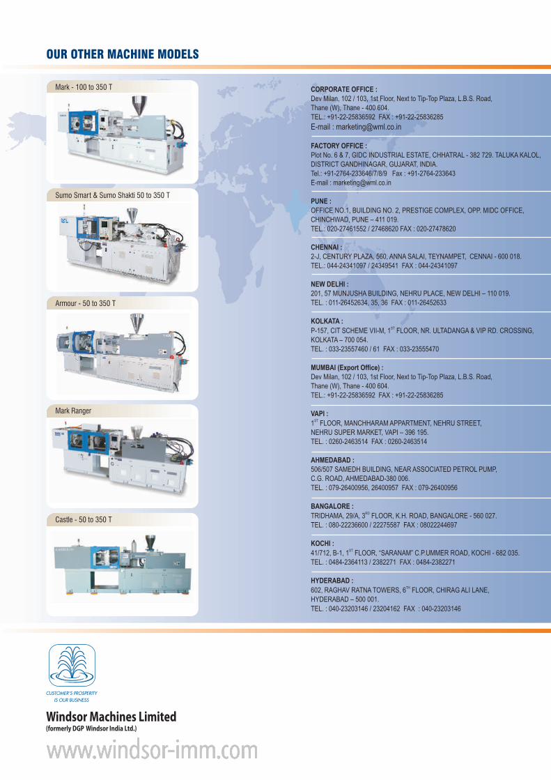
CORPORATE OFFICE :Dev Milan, 102 / 103, 1st Floor, Next to Tip-Top Plaza, L.B.S. Road,Thane (W), Thane - 400 604.TEL.: +91-22-25836592 FAX : +91-22-25836285
E-mail : [email protected]
FACTORY OFFICE :Plot No. 6 & 7, GIDC INDUSTRIAL ESTATE, CHHATRAL - 382 729. TALUKA KALOL, DISTRICT GANDHINAGAR, GUJARAT, INDIA.Tel.: +91-2764-233646/7/8/9 Fax : +91-2764-233643E-mail : [email protected]
PUNE :OFFICE NO.1, BUILDING NO. 2, PRESTIGE COMPLEX, OPP. MIDC OFFICE,CHINCHWAD, PUNE – 411 019.TEL.: 020-27461552 / 27468620 FAX : 020-27478620
CHENNAI :2-J, CENTURY PLAZA, 560, ANNA SALAI, TEYNAMPET, CENNAI - 600 018.TEL.: 044-24341097 / 24349541 FAX : 044-24341097
NEW DELHI :201, 57 MUNJUSHA BUILDING, NEHRU PLACE, NEW DELHI – 110 019.TEL. : 011-26452634, 35, 36 FAX : 011-26452633
KOLKATA :STP-157, CIT SCHEME VII-M, 1 FLOOR, NR. ULTADANGA & VIP RD. CROSSING,
KOLKATA – 700 054.TEL. : 033-23557460 / 61 FAX : 033-23555470
MUMBAI (Export Office) :Dev Milan, 102 / 103, 1st Floor, Next to Tip-Top Plaza, L.B.S. Road,Thane (W), Thane - 400 604.TEL.: +91-22-25836592 FAX : +91-22-25836285
VAPI :ST1 FLOOR, MANCHHARAM APPARTMENT, NEHRU STREET,
NEHRU SUPER MARKET, VAPI – 396 195.TEL. : 0260-2463514 FAX : 0260-2463514
AHMEDABAD :506/507 SAMEDH BUILDING, NEAR ASSOCIATED PETROL PUMP,C.G. ROAD, AHMEDABAD-380 006.TEL. : 079-26400956, 26400957 FAX : 079-26400956
BANGALORE :RDTRIDHAMA, 29/A, 3 FLOOR, K.H. ROAD, BANGALORE - 560 027.
TEL. : 080-22236600 / 22275587 FAX : 08022244697
KOCHI :ST41/712, B-1, 1 FLOOR, “SARANAM” C.P.UMMER ROAD, KOCHI - 682 035.
TEL. : 0484-2364113 / 2382271 FAX : 0484-2382271
HYDERABAD :TH602, RAGHAV RATNA TOWERS, 6 FLOOR, CHIRAG ALI LANE,
HYDERABAD – 500 001.
TEL. : 040-23203146 / 23204162 FAX : 040-23203146
OUR OTHER MACHINE MODELS
Mark - 100 to 350 T
Sumo Smart & Sumo Shakti 50 to 350 T
Armour - 50 to 350 T
Mark Ranger
Castle - 50 to 350 T