
RACB Belgian Max challenge regulations Technical 2018 · 2018-03-22 · Motoren – Rotax DD2 EVO...
24
RACB Belgian Max challenge Technical regulations 2018 DD2/DD2M
Transcript of RACB Belgian Max challenge regulations Technical 2018 · 2018-03-22 · Motoren – Rotax DD2 EVO...

RACB
Belgian Max challenge
Technical regulations 2018
DD2/DD2M
Technical Regulations ROTAX DD2 /master
6.00 Chassis
Maximum one chassis per event (weekend). Only original DD2 certificated chassis are allowed. Check www.rotax-kart.com / approved chassis DD2.
6.01 Brakesystem
Only hydraulic, CIK/FIA homologated brakes are allowed. The homologation sheet has to be available at any time. Front brakes are mandatory. Between the master brake cylinder and the brake pedal an extra security brake cable is mandatory. Minimum 1,8mm thickness. Also an extra security clip is mandatory at the brakepads. A ceramic brake disc is not allowed.
6.02 Rear axle
Diameter Ø40mm magnetic material, in a whole.
Wall thickness Minimum 2,9mm (entire lenght.)
6.03 Rims Aluminium or magnesium/diameter 5 inch
Dry Maximum 135/215mm / measured to the outside of the rim
Rain Maximum 130/180mm +/- 5mm / measured to the outside of the rim
Rear width Maximum 140cm / measured to the outside of the rim Minimum : see 6.05 “rear bumper”
Any additions to the rims are not allowed. Except : adhesive balancing lead. Beat retaining screws are mandatory.
6.04 Tyres
Slicks MOJO D5 Voor: 4,5x10x5 Achter: 7,1x11x5
Rain MOJO W3 Voor: 4,5x10x5 Achter: 6,0x11x5
Slick race tyres must be ordered in advance through the organisation by means of a voucher (see sporting regulations). Two sets of tyres are allowed for each meeting. It is allowed to mix the tyres during the event. Tires must be mounted according to the direction of rotation defined on the tire. It is not allowed to modify the tyres. The brand name, code number, barcode and the indications always need to be visible on the tyres. Only normal air is allowed to fill the tyres.

6.05 /
Rearbumper
Rearbumper supplied by Rotax is mandatory Only original Rotax rollers orange or red are allowed to be used. All parts from the rearbumper should be mounted. It is allowed to fix a saftey cable for the numberplate
6.06/
Side-pods
Frontspoiler for steering column
The plastic rear bumper must be CIK homologated and cover at least 2/3 of the rear wheels, and may not protrude the rear tyres. Only a CIK homologated clickable front bumper is allowed.
6.07/
Fueltank
The plastic fueltank should be mounted in a correct way, at the appropriate place. All vents must culminate in a reservoir.
6.08/
Age
DD2: 15 years – 31 years (ore reach the age of 15 in 2018)
DD2 Master: As from 32 years
6.09/
Weight and
clothing
DD2: Minimum 175 kg. Kart + complete race gear.
DD2 Master: Minimum 175 kg + complete race gear.
Complete equipment must comply with the CIK regulations A turbo visor is allowed in case of rain Gloves which cover the entire hand High shoes that cover and protect the ankles. The responsible doctor on the event may, for safety reasons, disapprove certain types of breast, neck or rib protections. A neck protection is not required yet recommended
From the moment when the driver goes on track, he must wear the mandatory race gear as described in this article.
6.10/
Startingnumbers
DD2: Yellow plate with black digits (Range : 601 t/m 649)
DD2 Master: Yellow plate with black digits ór
Green plate with white digits (Range : 651 t/m 699)
(Front, rear, left and right sides)
6.11 /
Seat / Extra seat
support
The seat has to be fixed at minimum 4 places, 2 at the top (left and right) and 2 on the bottom (left and right) All seat supports have to be fixed with washers with a minimum thickness of 1,5mm and a diameter of 40mm. On the engine side maximum one additional seat support is allowed to be used. The additional seat support must be fastened to the engine using the threaded hole designed for this purpose.
6.12 /
Lead
Drivers who are lighter than the required minimum weight shall attach extra weight on their kart, until they reach the prescribed weight. Lead may only be installed on the chassis or on the seat. The Technical Scrutineering can force each driver to mount the lead on another place. The lead shall be mounted so that everyone’s security is guaranteed at all times:
Up to 3kg: at least with 2x M6 bolts
Up to 6kg: at least with 2x M8 bolts
Up to 10kg: at least 4x M8 bolts

6.13 /
Data Systems
Data logging with or without a GPS module is allowed. Data from the GPS module may only be saved systems which has been mounted on the kart. Every other form of telemetry or radio communication is not allowed. Transferring data during sessions to a device, other than the data logger on board is not allowed. Power to activate the data system should be taken from a separate battery. It is not allowed to take power from the battery that is mend for the engine.
6.14 /
Cameras
Drivers may use a camera if mounted in an appropriate way and accepted by the Scrutineers. Helmet cameras are not allowed. Clips, etc, for mounting a camera may not be fit on the helmet.

Motoren – Rotax DD2 EVO
6.15 /
Foreword
These regulations will be valid as of 1st of February 2018 and will replace all previous regulations. Only originals spare parts which are manufactured by Rotax BRP are legal to be used. Any modifications are not allowed. Eventually helix reparations with heli coils and/or wire bushes are allowed.
6.16 /
Engines
Each race-meeting its allowed to enter two engines. The engines should be sealed with an official Rotax seal. The engine registration card has to be available at any time.
6.17 /
Squish
Measuring
Minimum 1,30mm (including possible carbon deposits) Engine temperature below 30 degrees Celcius. The squish gap must be measured with a certified slide gauge and by using a 2 mm tin wire (Rotax part no. 580 130). The crankshaft must be turned by hand slowly over top dead centre to squeeze the tin wire. The squish gap must be measured on the left and right side in the direction of the piston pin. The average value of the two measurements counts.
6.18 /
Cilinderhead
insert
Cast identification code has to be "223 389" or "223 389 1" or "223 389 2" or 223 389 2/1" or “223 389 2/2”. Casted wording "ROTAX" and/or "MADE IN AUSTRIA" must be shown.
Height of the combustion chamber insert has to be 27,55mm, (+0,0/-0,1mm)(A)
and 28,80mm ± 0,2mm (B)

The profile of the combustion chamber insert has to be checked with a template (ROTAX part no. 277390). The crack of light between the template and the profile of the combustion chamber insert has to be the same over the whole profile.
6.19 /
Cylinder
head
It is allowed to change the colour of the cilinderhead cover for indentification.
6.20 /
Piston with
ring
assembly
Original, coated, aluminium, cast piston with one piston ring. The piston has to show on the inside the cast wording "ELKO" (1) and "MADE IN AUSTRIA" (2)
Machined areas are: Top end of piston, outside diameter, groove for the piston ring,bore for the piston pin, inside diameter at bottom end of piston and some pre -existing factory removal (3) of flashing at the cut out of the piston skirt. All other surfaces are not machined and have cast surface. Any mechanical treatment or rework of the piston is forbidden, (e.g. removal of carbon deposits). Cleaning without changing the original surface is allowed. Original, magnetic, rectangular piston ring. Ring height : 0,98 +/- 0,02 mm. Piston ring is marked either with "Rotax 215 547", "Rotax 215 548" or Rotax 215 548X The piston ring is legal also if just parts of the marking are still visible.
6.21 / Piston
pin
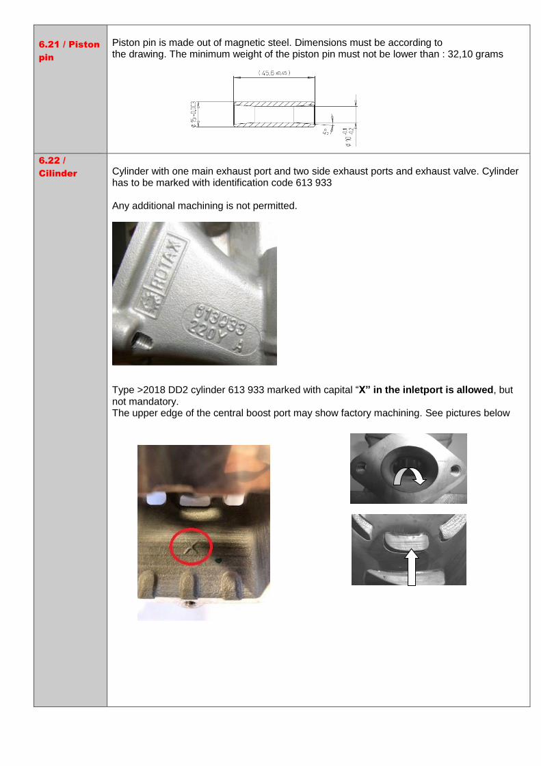
Piston pin is made out of magnetic steel. Dimensions must be according to the drawing. The minimum weight of the piston pin must not be lower than : 32,10 grams
6.22 /
Cilinder
Cylinder with one main exhaust port and two side exhaust ports and exhaust valve. Cylinder has to be marked with identification code 613 933 Any additional machining is not permitted.
Type >2018 DD2 cylinder 613 933 marked with capital “X” in the inletport is allowed, but not mandatory. The upper edge of the central boost port may show factory machining. See pictures below

6.23 /
Maximum
bore
54,035mm (measured 10mm above the exhaust port)
6.24 /
Cylinder
measures
Height of cylinder should be 86,7mm (-0,05 / + 0,10mm) Exhaust port timing The "exhaust port timing" (distance from the top of the cylinder to the top of the exhaust port) has to be checked by means of the template (ROTAX part no. 277 402). Insert the template for DD2 Max cylinder into the cylinder, and move the template (at the highest point of the exhaust port) as far as possible into the exhaust port. In this position the template may not touch the cylinder wall Any modification is strictly forbidden! All transfer ports and passages have cast finish surface except some removal (done by the manufacturer) of cast burr at the inlet passage, exhaust port and passages. All ports have chamfered edges to prevent ring snagging. Any additional machining is not permitted. The top edge of exhaust port may show some pre-existing machining from the manufacturer. The sealing flange for the exhaust socket may show signs of machining from the manufacturer. All ports have chamfered edges. Any additional machining is not permitted.
Cylinders with code 613 933 the upper edge of the central boost may show factory machining. See picture.

The top edge of the exhaust port may show either just a cast finish surface or signs of a CNC machining or sign of CNC machining in combination with sign of manual grinding.
The flange for the exhaust socket may show either cast finish or machined surface. Machined surface can be either flat or show a circular sealing bump.

6.25 /
Power valve
Electronic timed system must be used only. System has to be used with all components fitted as shown in the illustration below. Only green coloured exhaust below (item 10) (Rotax nr 260723) is legal to be used. The original compression spring has to be used. Fitting an original impulse nozzle (1) into the pressure hose in an allowed adjustment. The direction of the impulse nozzle inside the pressure hose is free. . Length of the exhaust valve : 36,50mm + 0,20/ -0,30mm (see picture) Width of collar 4,80mm ± 0,30mm (see picture) Any modification is not allowed.

Power valve If the piston is moved in direction top of cylinder and first time covering completely the exhaust port, it must be possible to insert the exhaust valve gauge (277 030) until it stops at the surface of the cylinder. This template must be at all times fully connected to the cylinder surface. It should not be possible to put a filler gauge of 0.05mm between. Only the original gasket between cylinder and powervalve house is allowed. Modifications are not allowed.
6.27 / Inlet
systeem
The inlet manifold is marked with the identification code 267 410 of 267 411 Some factory flash removal may be present at the conjunction of the inside contour and the carburettor stop mounting face. No additional grinding or machining is permitted. The reed valve assy. is equipped with 2 petal stops and 2 reeds, each having 3 petals. The thickness of the reeds is 0,60 mm +/- 0,10mm. Modification is not allowed.
6.28 /
Conrod and
Crankshaft
Stroke: 54,5mm ± 0,1mm Con rod has to show forged numbers “367” or “362” (see pictures)
Shafts of con rods are not machined. Grinding or polishing of shaft of con rod is not permitted.

Crankshaft has to be unprocessed and may not be damaged. Ignition signal on crankshaft :
Fit the template (Rotax 277391) on the crankshaft. Align the hole in the template for the big end pen with the big end pin of the crankshaft. The two edges of the signal machining on the crankshaft must be in line (+/-0,5mm) with the corresponding edges (MAX) of the template.
6.29 / 2-
speed
gearbox
Primary shaft with 19 teeth for 1st gear and 24 teeth for 2nd gear Idle gear for 1st gear has to have 81 teeth Idle gear for 2nd gear has to have 77 teeth
6.30 /
Balance
drive
Balance drive gear must be fitted on crank shaft. Balance gear must be fitted on primary shaft and must be aligned with the balance drive gear according to the instruction in the repair manual. Version 1: Fly weight of balance gear must show cast surface Version 2: Fly weight of balance gear can show machined surface. Dimension A (widest part of balance weight) must be either 53,0mm +/- 0,5 or 57,0 mm +/- 0,5 The minimum weight of a dry balance gear including bearing must not be lower than 240 grams.
A
6.31 /
Centrifugal
clutch
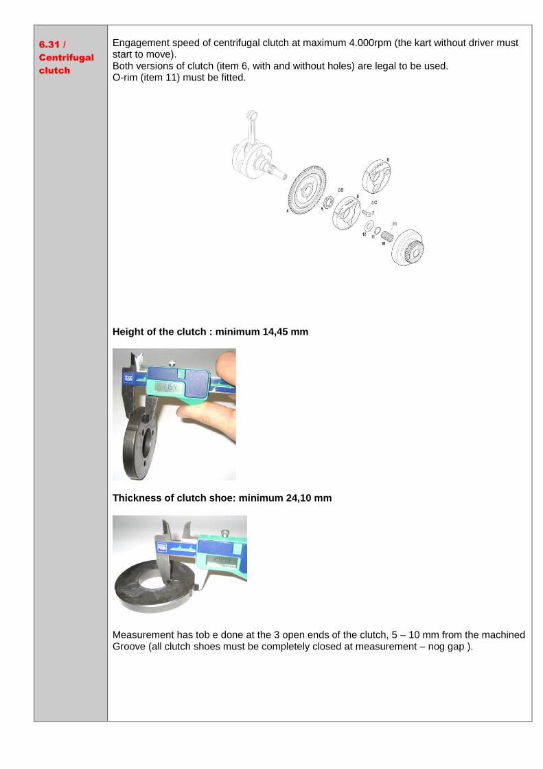
Engagement speed of centrifugal clutch at maximum 4.000rpm (the kart without driver must start to move). Both versions of clutch (item 6, with and without holes) are legal to be used. O-rim (item 11) must be fitted. Height of the clutch : minimum 14,45 mm
Thickness of clutch shoe: minimum 24,10 mm
Measurement has tob e done at the 3 open ends of the clutch, 5 – 10 mm from the machined Groove (all clutch shoes must be completely closed at measurement – nog gap ).
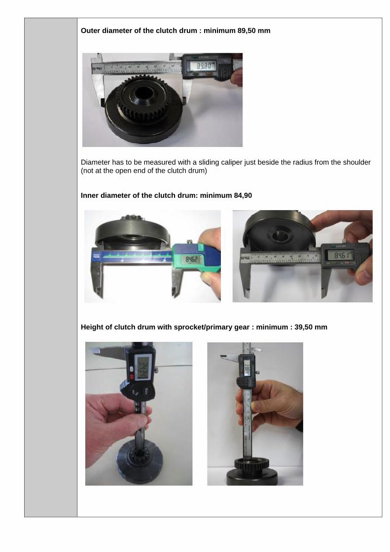
Outer diameter of the clutch drum : minimum 89,50 mm
Diameter has to be measured with a sliding caliper just beside the radius from the shoulder (not at the open end of the clutch drum) Inner diameter of the clutch drum: minimum 84,90
Height of clutch drum with sprocket/primary gear : minimum : 39,50 mm
6.32 /
Primary
drive
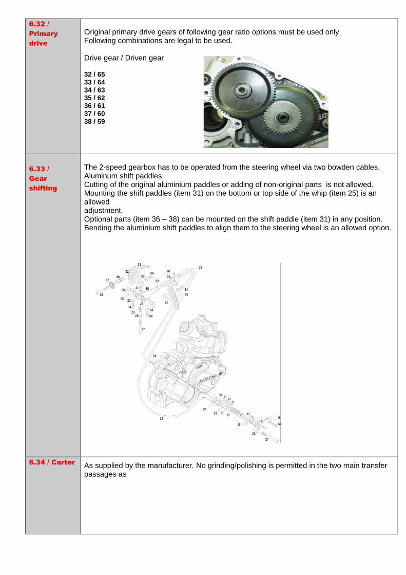
Original primary drive gears of following gear ratio options must be used only. Following combinations are legal to be used. Drive gear / Driven gear 32 / 65 33 / 64 34 / 63 35 / 62 36 / 61 37 / 60 38 / 59
6.33 /
Gear
shifting
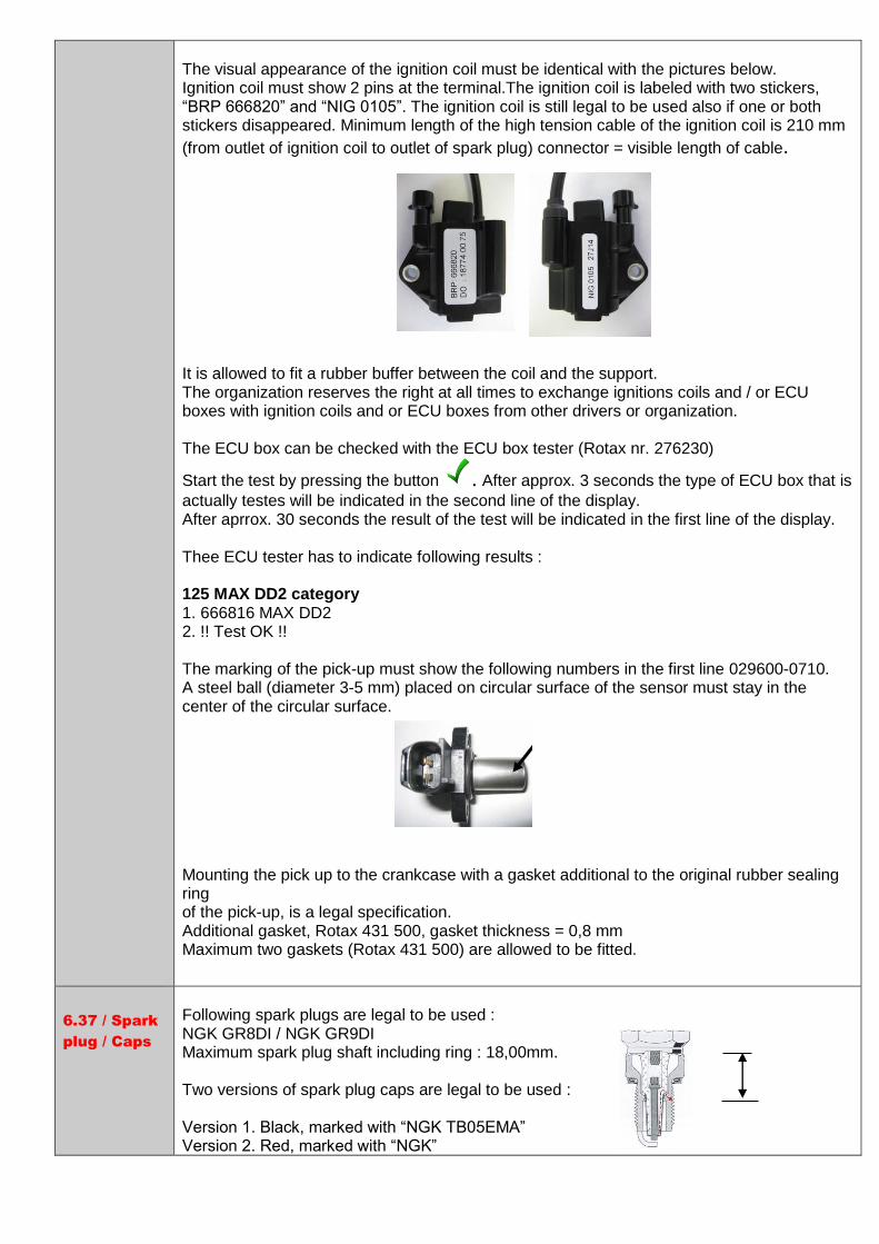
The 2-speed gearbox has to be operated from the steering wheel via two bowden cables. Aluminum shift paddles. Cutting of the original aluminium paddles or adding of non-original parts is not allowed. Mounting the shift paddles (item 31) on the bottom or top side of the whip (item 25) is an allowed adjustment. Optional parts (item 36 – 38) can be mounted on the shift paddle (item 31) in any position. Bending the aluminium shift paddles to align them to the steering wheel is an allowed option.
6.34 / Carter
As supplied by the manufacturer. No grinding/polishing is permitted in the two main transfer passages as

6.35 /
Crankshaft
main
bearings
Crankshaft main bearing 6206 from FAG is allowed only. (must be marked with code 579165BA of Z-579165.11.KL)
6.36 /
Ignition
system
DD2 EVO Dellorto ignition system. Ignition coil with separate electronic ECU box (Rotax nr. 666820). The ECU box is still legal to be used if the sticker is removed. At the mounting versions as shown in the left illustrations, the ground cable of the cable harness has to be connected to the lower rubber buffer of the support plate.
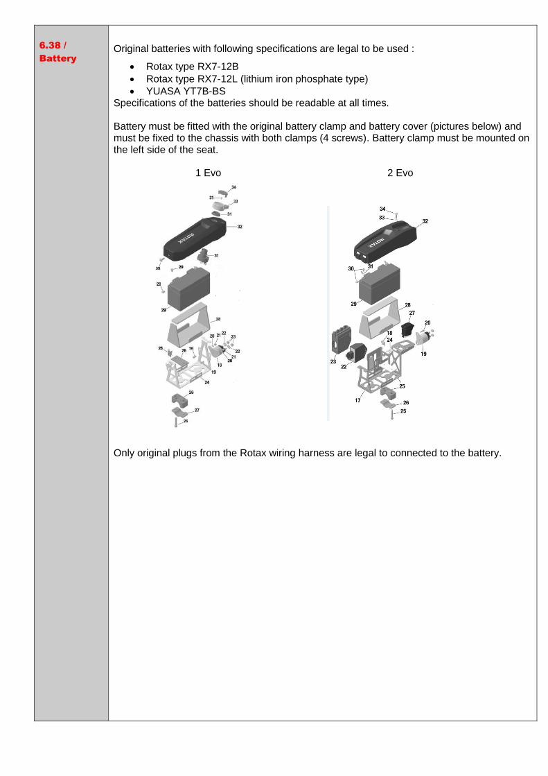
The visual appearance of the ignition coil must be identical with the pictures below. Ignition coil must show 2 pins at the terminal.The ignition coil is labeled with two stickers, “BRP 666820” and “NIG 0105”. The ignition coil is still legal to be used also if one or both stickers disappeared. Minimum length of the high tension cable of the ignition coil is 210 mm
(from outlet of ignition coil to outlet of spark plug) connector = visible length of cable. It is allowed to fit a rubber buffer between the coil and the support. The organization reserves the right at all times to exchange ignitions coils and / or ECU boxes with ignition coils and or ECU boxes from other drivers or organization. The ECU box can be checked with the ECU box tester (Rotax nr. 276230)
Start the test by pressing the button . After approx. 3 seconds the type of ECU box that is
actually testes will be indicated in the second line of the display. After aprrox. 30 seconds the result of the test will be indicated in the first line of the display. Thee ECU tester has to indicate following results : 125 MAX DD2 category 1. 666816 MAX DD2 2. !! Test OK !! The marking of the pick-up must show the following numbers in the first line 029600-0710. A steel ball (diameter 3-5 mm) placed on circular surface of the sensor must stay in the center of the circular surface. Mounting the pick up to the crankcase with a gasket additional to the original rubber sealing ring of the pick-up, is a legal specification. Additional gasket, Rotax 431 500, gasket thickness = 0,8 mm Maximum two gaskets (Rotax 431 500) are allowed to be fitted.
6.37 / Spark
plug / Caps
Following spark plugs are legal to be used : NGK GR8DI / NGK GR9DI Maximum spark plug shaft including ring : 18,00mm. Two versions of spark plug caps are legal to be used : Version 1. Black, marked with “NGK TB05EMA” Version 2. Red, marked with “NGK”
6.38 /
Battery
Original batteries with following specifications are legal to be used :
Rotax type RX7-12B
Rotax type RX7-12L (lithium iron phosphate type)
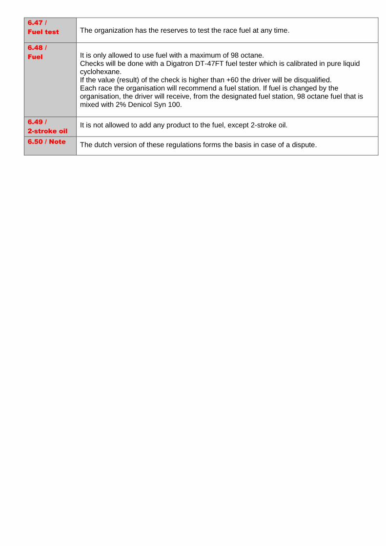
YUASA YT7B-BS Specifications of the batteries should be readable at all times. Battery must be fitted with the original battery clamp and battery cover (pictures below) and must be fixed to the chassis with both clamps (4 screws). Battery clamp must be mounted on the left side of the seat. 1 Evo 2 Evo Only original plugs from the Rotax wiring harness are legal to connected to the battery.

6.39 /
Carburetor
DELLORTO Type VHSB 34. Housing has to show the cast wording “VHSB 34”. Carburettor housing is stamped with “XS”. The complete inlet bore of the carburettor must show cast surface. Carburettor slide shows digits “45” in casting Following specifiacations:
Carburettor venturi insert 12,5.
Needle jet stamped with “DP267”.
Jet needle stamped with “K57”.
Start jet stamped with “60”.
Idle jet stamped with “60”.
Idle emulsion tube stamped with “45”.
Float lever according template (Rotax nr. 277400.)
Floats marked “4,0 gr” are legal to be used only.
Needle valve assembly stamped “150”. Needle of needle valve marked with diamond symbol “INC” only.
All jets must be correctly seated and securely fitted at any time (tightened)!
Settings of the carburettor adjustment screws (idle and idle air) are free.
Settings of main jets is free.
Optional carburettor plug (Rotax nr. 261030) is legal to be used. Only original Dellorto parts are legal to be used. Even if not supplied by Rotax. See checklist DELLORTO for further info.
6.40 /
Fuel pump
MIKUNI fuel pump, type DF 44-210 is mandatory. Fuel pump must be mounted on the support bracket, marked 651 055, attached to the clutch cover :
Mounting the fuel with the two originals rubber buffers to the chassis is an allowed option. In this case the fuel pump must me mounted below the inlet center line of the carburetor.

6.41 /
Fuel filter
It is not mandatory to mount a fuel filter, but if a fuel filter is mounted only the version showed in the picture below is allowed :
Except the fuel line, the fuel pump and the original fuel filter no additional parts are legal to be mounted between the fuel tank and carburettor.
6.42 /
Radiateur
The removal of the thermostat from the cylinder head cover is an allowed modification. Radiator must be mounted wilt all components. Any tape is not allowed. It is an allowed modification to use a plastic plate/flap to control the air flow through the radiator. Any other non-original device to control the air flow through the radiator is prohibited. The radiator has to be mounted on the left side of the driver seat. Only the following version is allowed to be used : Rotaxnr. 295 926, (version 2, with or without cooling flap) Cooling area : Height: 290 mm Width: 138 mm Thickness of radiator: 34mm
6.43 /
Engine
coolant
Plain water without any additives has to be used. The venting of the radiator should end in a reservoir.

6.44 /
Intake
silencer
Intake silencer with integrated, washable air filter has to be used with all parts. and has to be mounted on the support bracket with two screws (in dry and wet conditions). Only original Rotax parts are legal to be used. The intake silencer case (pos 1) is marked on the inside with the Rotax part no. 225 012
(4 clips) or 225 013 (5 clips). The intake silencer cover (pos 2) is marked on the inside with the Rotax part no. 225 022
(4 clips) or 225 023 (5 clips). Two versions of air filters (pos 3) are legal to be used. Version 1, with integrated steel frame. Version 2, with separate plastic frame (pos 4). At intake silencer cover (pos. 2, Rotax part no. 225 022), it is mandatory to fit the O-ring (pos. 6) on the intake silencer tube (pos. 5)
The air filter must be assembled between the intake silencer case and the intake silencer cover that the whole area of the intake silencer case is covered. Sealing the top of the intake silencer using adhesive tape is an allowed modification. At wet condition it is not allowed to attach anything to the air box to protect the air inlet from
water spray.

6.45
Exhaust
flange
The measurement (C) must be at least 15,5mm Only restrictor Rotax.nr. 273190 including seal ring is legal to be used.
6.46 /
Exhaust
system
Original exhaust system as supplied by Rotax is mandatory to be used. Exhaust system, Rotax EVO (Rotax part nr. 273 180) is mandatory. Turned pipe with 180° elbow and silencer are two separate pieces. The silencer is fixed with two springs to the 180° elbow and two springs to the tuned pipe. To fit a 3rd original spring (crosswise at the ball joint connection between 180° elbow and silencer) is an allowed option. The silencer has to be mounted in a position where the direction of the 90° elbow outlet (direction of the hot exhausts gasses) does not harm any component of the chassis. The original design silencer end cap with 90° elbow is mandatory to be used. The original Rotax isolating mat (Rotax nr. 297981) is mandatory. Replacing the perforated cover and isolating mat are legal to be replaced by original Rotax parts. The isolating mat should cover the perforated cover at any time. Replacing the original rivets of the silencer end cap by 4mm metric screws and corresponding locking nuts is an allowed modification.

Additional to the standard isolation mat a steel isolation mat (Rotax part nr. 297983) of the square dimension of 165 (+10mm) is legal (not mandatory) to be assembled underneath the standard isolating mat according to the illustration below :
Clamp (1) must be fitted at a distance of 18 (+/-2mm), measured from the end of the tube. Clamp (2) must be fitted at the end of the perforated tube to the beginning of the steel isolating mat is a specification for assembly purpose only. Both clamps (1 and 2) are mandatory to be fitted and tightened. The exhaust system should be mounted to the chassis by using the two original mounting brackets. Rubber buffers are mandatory to be placed between the system and chassis. The use of maximum 4 pieces of original Rotax exhaust springs, to fix the exhaust system to the cylinder is allowed. Any other item is not allowed. Welding a socket on the top of the exhaust system for measuring the exhaust gas temperature is an allowed modification. Distance : 50-80mm from the ball joint. Welding at the exhaust system is only allowed in case of a repair. Modifications are not allowed. The organization reserves the right at all times to change exhaust systems from drivers with exhaust systems from the organization.
Length of
inlet cone
575 mm +/- 5mm,
Length of
cylindrical
part of
exhaust
pipe
80mm +/- 5mm
Lengte end
cone
240mm +/- 5mm (buitenom gemeten)
Diameter
hole end of
tube
Maximum 22,5mm
Total length
end
silcencer
Minimum 500mm +/- 1 mm
6.47 /
Fuel test
The organization has the reserves to test the race fuel at any time.
6.48 /
Fuel
It is only allowed to use fuel with a maximum of 98 octane. Checks will be done with a Digatron DT-47FT fuel tester which is calibrated in pure liquid cyclohexane. If the value (result) of the check is higher than +60 the driver will be disqualified. Each race the organisation will recommend a fuel station. If fuel is changed by the organisation, the driver will receive, from the designated fuel station, 98 octane fuel that is mixed with 2% Denicol Syn 100.
6.49 /
2-stroke oil
It is not allowed to add any product to the fuel, except 2-stroke oil.
6.50 / Note
The dutch version of these regulations forms the basis in case of a dispute.