search.jsp?R=20110015775 2018-04 … · Hydrodynamic Suspension System ... Safety/Reliability...
22
Engineering Test Directorate NASA Marshall Space Flight Center Huntsville, AL Michael Sachs Systems Engineer, ET40 https://ntrs.nasa.gov/search.jsp?R=20110015775 2018-06-26T05:03:59+00:00Z
Transcript of search.jsp?R=20110015775 2018-04 … · Hydrodynamic Suspension System ... Safety/Reliability...
Engineering Test Directorate NASA Marshall Space Flight CenterHuntsville, AL
Michael SachsSystems Engineer, ET40
https://ntrs.nasa.gov/search.jsp?R=20110015775 2018-06-26T05:03:59+00:00Z
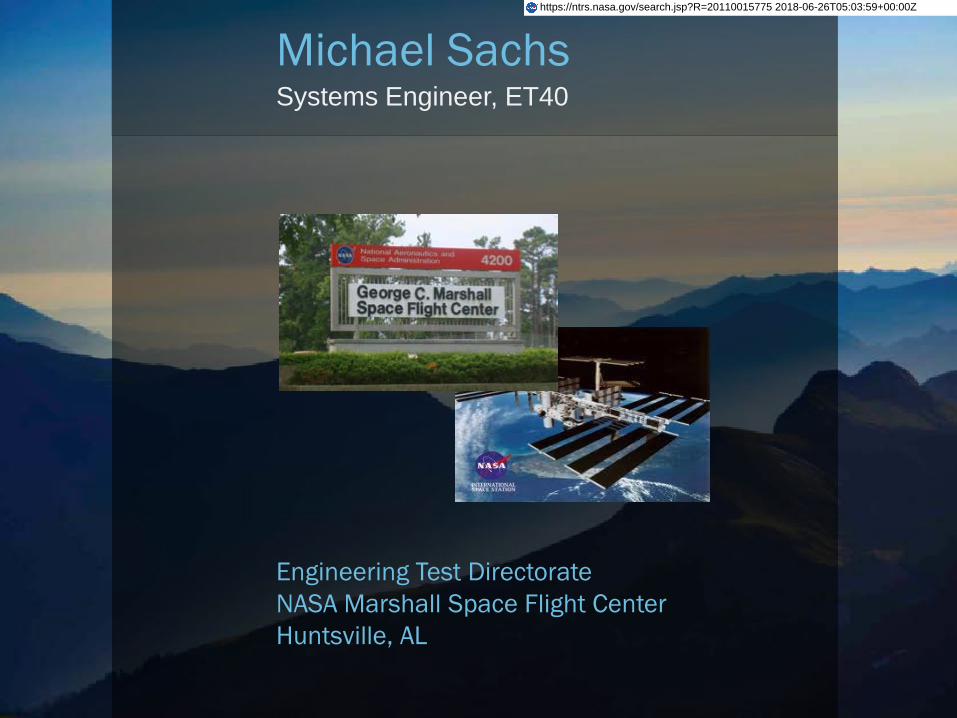
7,200,000 lb Lifting cap. 6 Axis DOF to simulate Free-Free boundary flight conditions. Strategically placed electro-dynamic shakers simulate thrust oscillation and acoustic shock.
Hydrodynamic Suspension System (HDS) Integral part of IVGVT allowing meas. of vehicle modal characteristicsVerification of FEM, improve GN&C stability, identify resonance anomalies
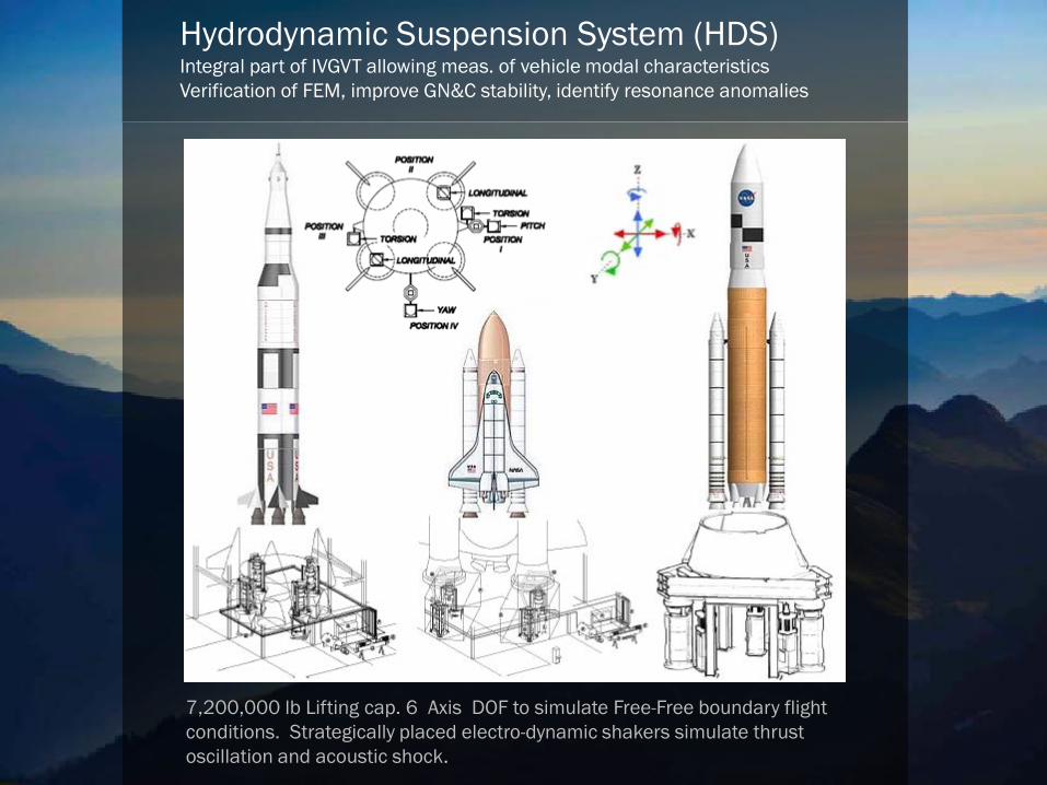
Unique Design: Hydraulic Lift + N2 Gas Spring. Nearly 100% inefficientbut 100% effective! Why? Continuous Hydraulic flow throughand across bearing surfaces.
HDS Piston and CylinderHydrodynamic Suspension System
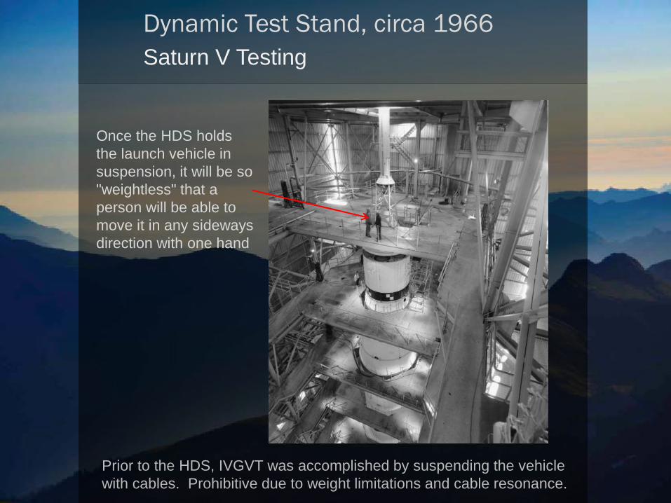
Dynamic Test Stand, circa 1966Saturn V Testing
Prior to the HDS, IVGVT was accomplished by suspending the vehiclewith cables. Prohibitive due to weight limitations and cable resonance.
Once the HDS holds the launch vehicle in suspension, it will be so "weightless" that a person will be able to move it in any sideways direction with one hand
Original HDS testing, circa 1965Martin Marietta Engineers
I wonder what a day around hydraulic oil doesto a white shirt and tie?
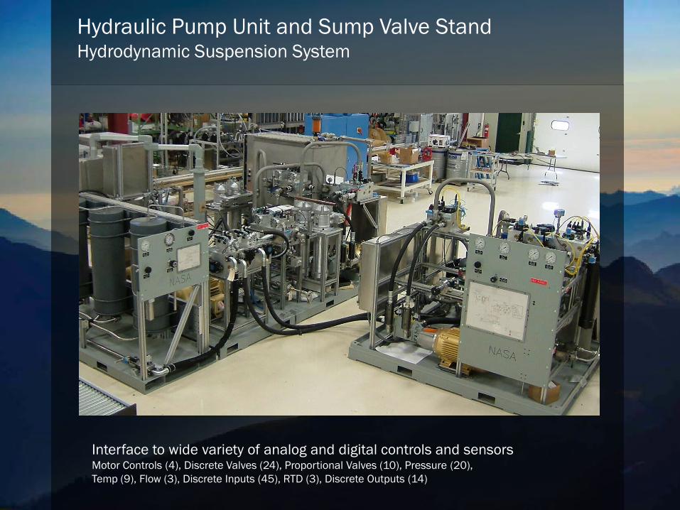
Hydraulic Pump Unit and Sump Valve StandHydrodynamic Suspension System
Interface to wide variety of analog and digital controls and sensorsMotor Controls (4), Discrete Valves (24), Proportional Valves (10), Pressure (20), Temp (9), Flow (3), Discrete Inputs (45), RTD (3), Discrete Outputs (14)
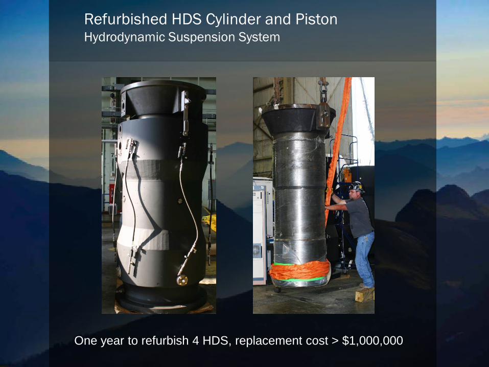
Refurbished HDS Cylinder and PistonHydrodynamic Suspension System
One year to refurbish 4 HDS, replacement cost > $1,000,000
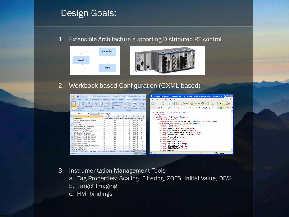
Design Goals:
1. Extensible Architecture supporting Distributed RT control
2. Workbook based Configuration (GXML based)
3. Instrumentation Management Toolsa. Tag Properties: Scaling, Filtering, ZOFS, Initial Value, DB%b. Target Imagingc. HMI bindings
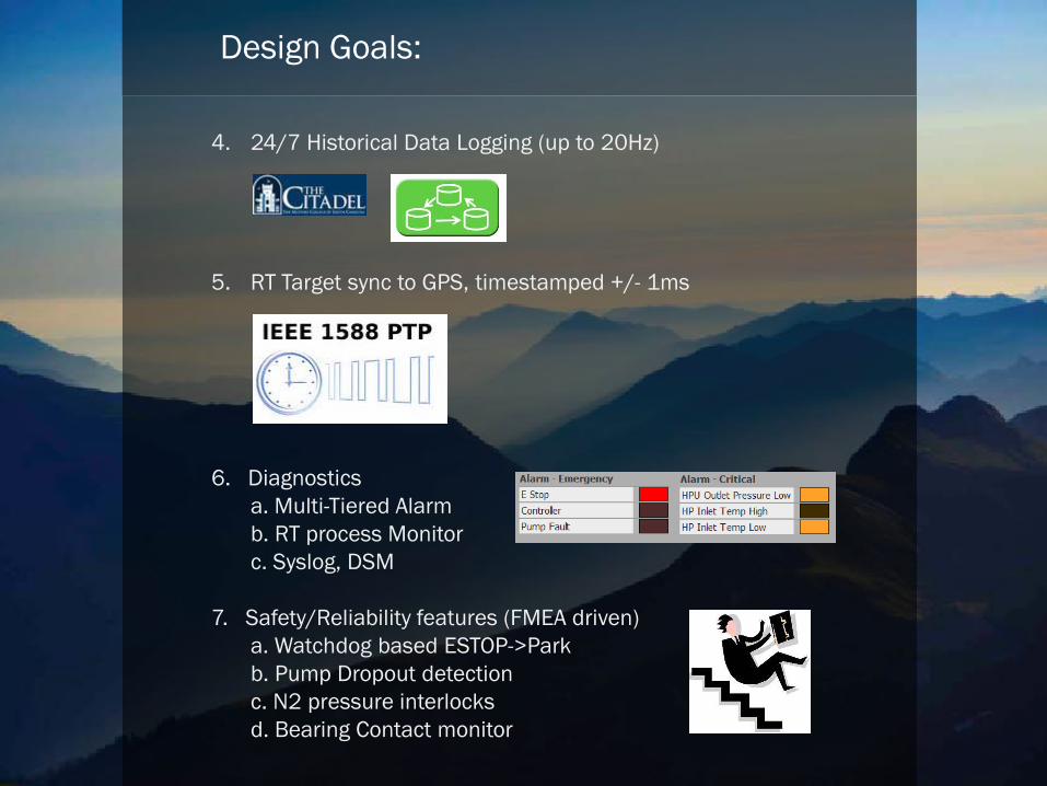
Design Goals:
4. 24/7 Historical Data Logging (up to 20Hz)
5. RT Target sync to GPS, timestamped +/- 1ms
6. Diagnosticsa. Multi-Tiered Alarmb. RT process Monitorc. Syslog, DSM
7. Safety/Reliability features (FMEA driven)a. Watchdog based ESTOP->Parkb. Pump Dropout detectionc. N2 pressure interlocksd. Bearing Contact monitor
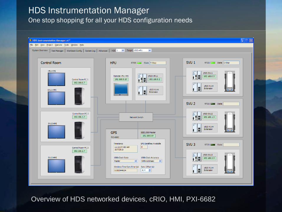
HDS Instrumentation ManagerOne stop shopping for all your HDS configuration needs
Overview of HDS networked devices, cRIO, HMI, PXI-6682
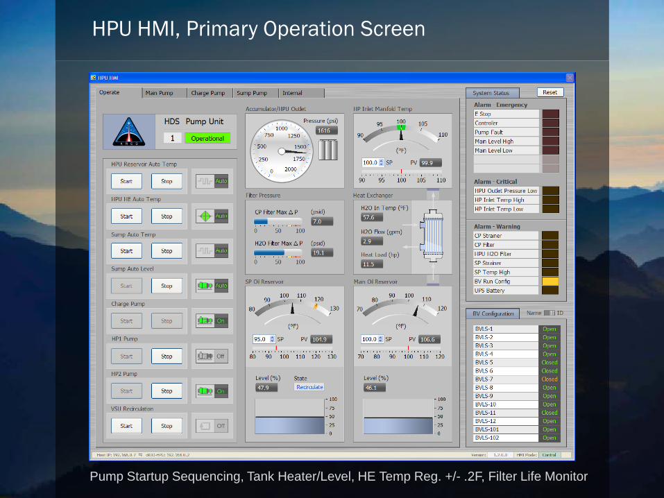
HPU HMI, Primary Operation Screen
Pump Startup Sequencing, Tank Heater/Level, HE Temp Reg. +/- .2F, Filter Life Monitor
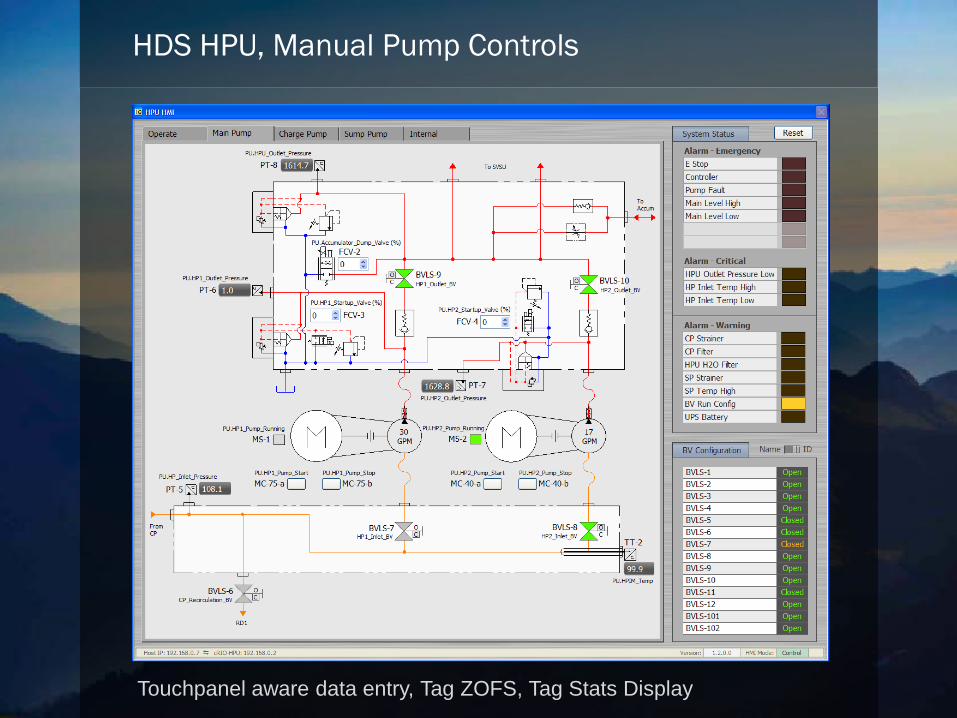
HDS HPU, Manual Pump Controls
Touchpanel aware data entry, Tag ZOFS, Tag Stats Display
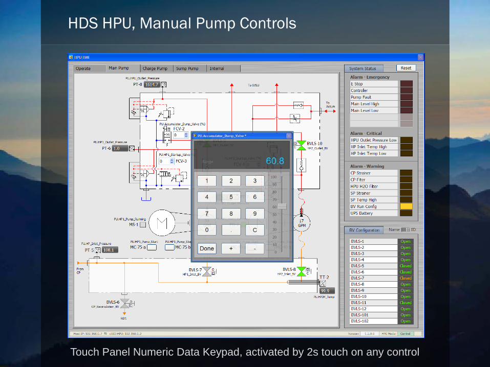
HDS HPU, Manual Pump Controls
Touch Panel Numeric Data Keypad, activated by 2s touch on any control
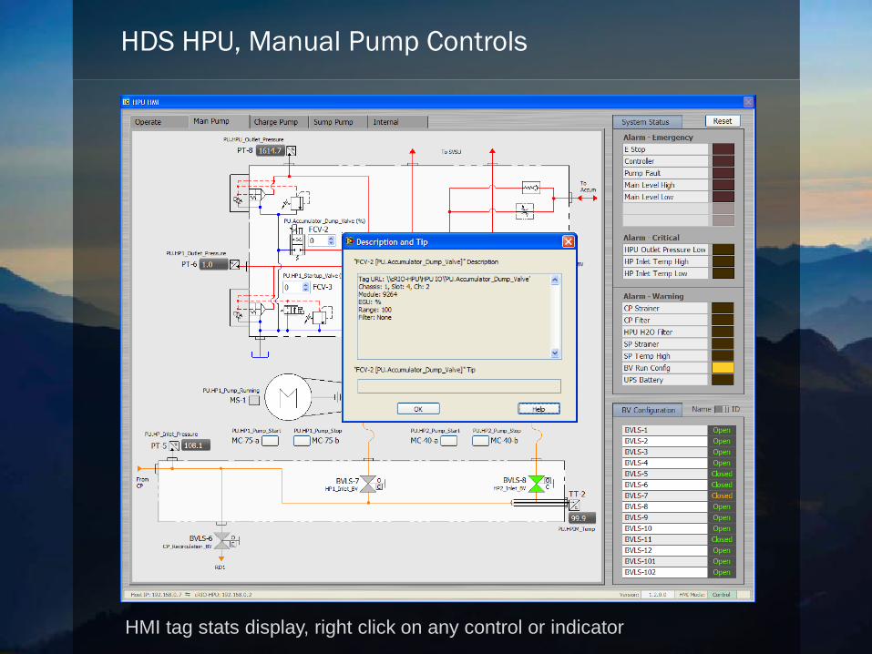
HDS HPU, Manual Pump Controls
HMI tag stats display, right click on any control or indicator
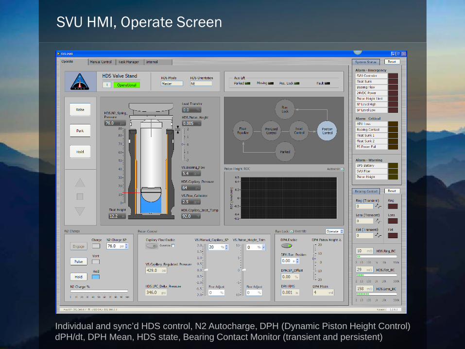
SVU HMI, Operate Screen
Individual and sync’d HDS control, N2 Autocharge, DPH (Dynamic Piston Height Control)dPH/dt, DPH Mean, HDS state, Bearing Contact Monitor (transient and persistent)
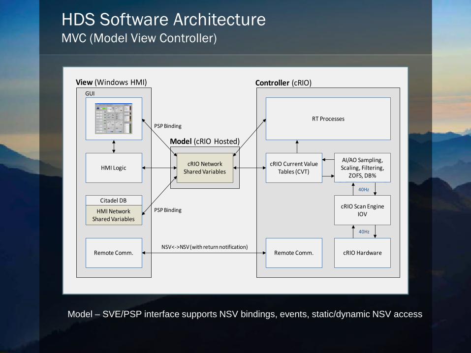
HDS Software ArchitectureMVC (Model View Controller)
HMI Logic
Citadel DB
HMI Network Shared Variables
Remote Comm.
View (Windows HMI)
cRIO Network Shared Variables
Model (cRIO Hosted)
GUIController (cRIO)
Remote Comm. cRIO Hardware
cRIO Scan Engine IOV
AI/AO Sampling, Scaling, Filtering,
ZOFS, DB%
cRIO Current Value Tables (CVT)
RT Processes
40Hz
40Hz
PSP Binding
PSP Binding
NSV<->NSV (with return notification)
Model – SVE/PSP interface supports NSV bindings, events, static/dynamic NSV access
Module
IOV
Scan Engine
NSV
cRIOPC
NSV
Citadel
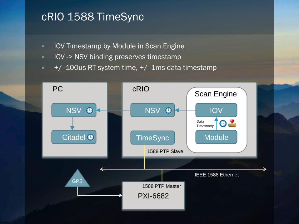
cRIO 1588 TimeSync
IOV Timestamp by Module in Scan Engine IOV -> NSV binding preserves timestamp +/- 100us RT system time, +/- 1ms data timestamp
DataTimestamp
PXI-6682
GPSIEEE 1588 Ethernet
TimeSync
1588 PTP Master
1588 PTP Slave
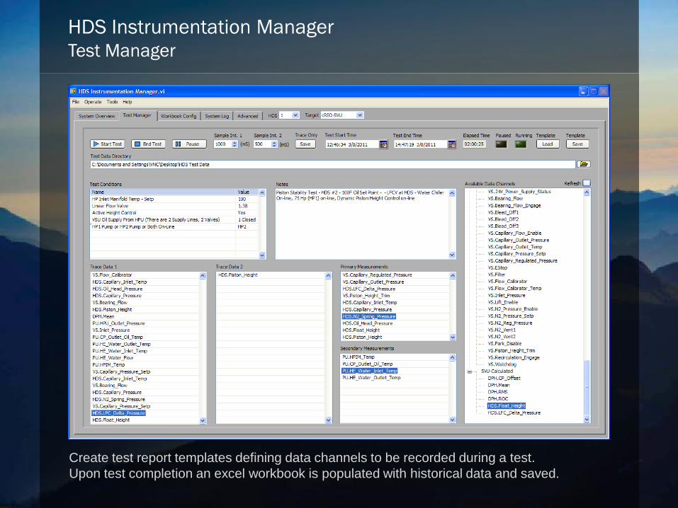
HDS Instrumentation ManagerTest Manager
Create test report templates defining data channels to be recorded during a test. Upon test completion an excel workbook is populated with historical data and saved.
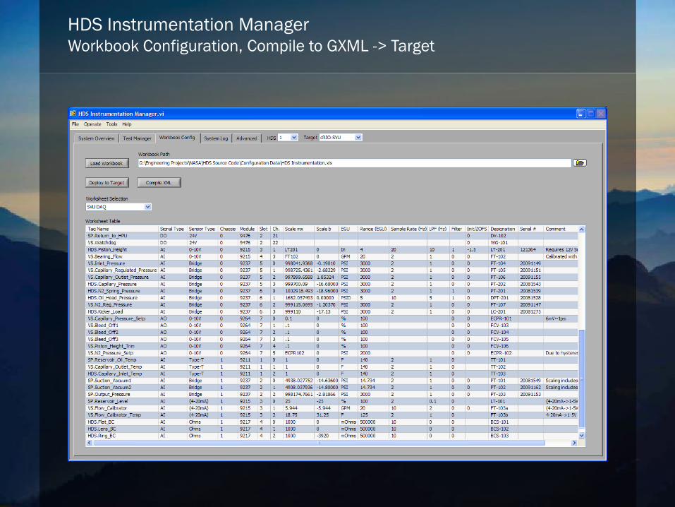
HDS Instrumentation ManagerWorkbook Configuration, Compile to GXML -> Target
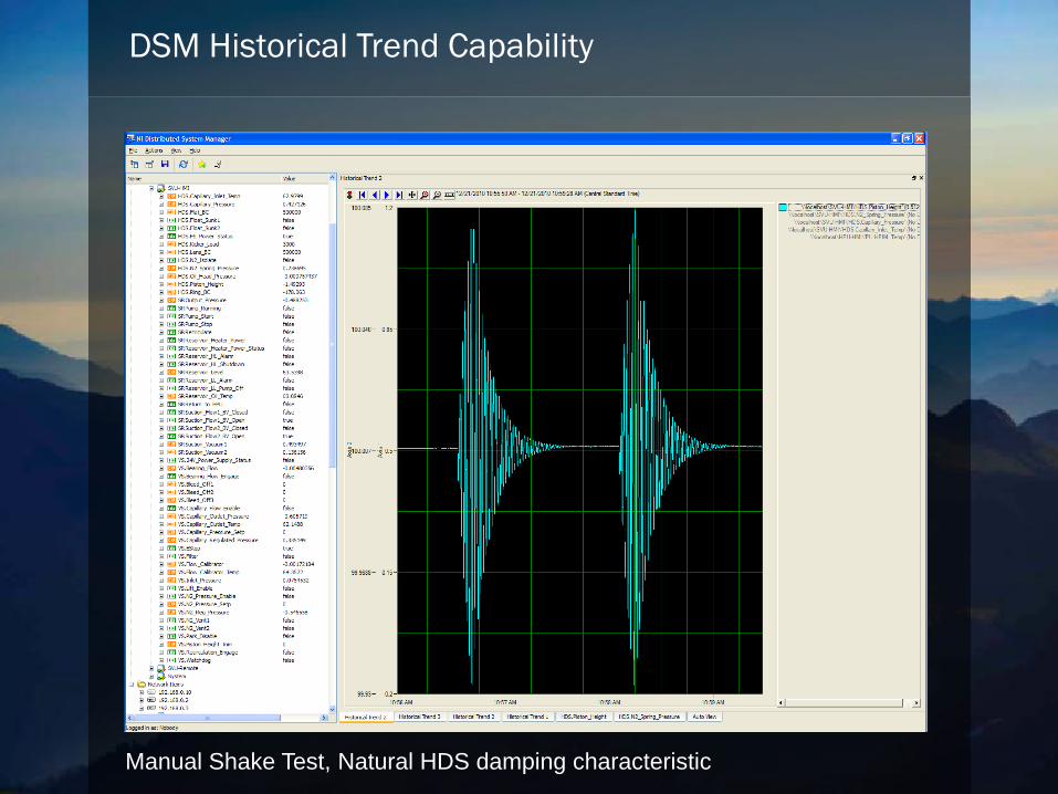
DSM Historical Trend Capability
Manual Shake Test, Natural HDS damping characteristic
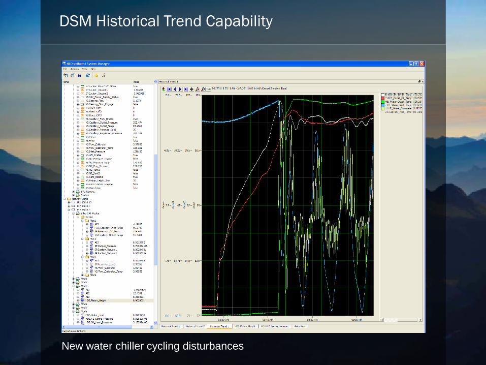
DSM Historical Trend Capability
New water chiller cycling disturbances
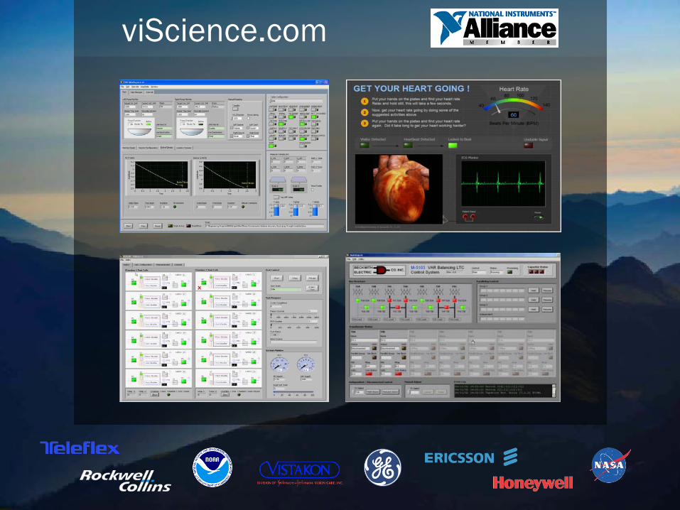
viScience.com