![PACKAGEHEATPUMPSFEATURING INDUSTRYSTANDARDR-410A REFRIGERANT · []indicatesmetricconversion installationinstructions packageheatpumpsfeaturing industrystandardr-410a refrigerant rqrm15/16seerseries–(2](https://static.fdocuments.us/doc/165x107/5becfdaf09d3f270058ba733/packageheatpumpsfeaturing-industrystandardr-410a-indicatesmetricconversion.jpg)
R-410A Refrigerant Single Stage 3-5 Ton · R-410A Refrigerant Single Stage 3-5 Ton ... Aurora Base...
37
Premium Hydronic System H Series HE R-410A Refrigerant Single Stage 3-5 Ton INSTALLATION, OPERATION & MAINTENANCE MANUAL TEC-IOM-HE_0215v2 Installation Information Water Piping Connections Electrical Startup Procedures Troubleshooting Preventative Maintenance a p p a t ti tion Informati tion on pi ping ng C Con onne nect ctio ions ns El Elec e trical artup p Pr Proc oced edur ures es Troubl b eshoot otin ng g ive v ve M M Mai int nten enance
Transcript of R-410A Refrigerant Single Stage 3-5 Ton · R-410A Refrigerant Single Stage 3-5 Ton ... Aurora Base...

Premium Hydronic System
H Series HE R-410A Refrigerant
Single Stage3-5 Ton
INST
ALL
ATI
ON
, OPE
RA
TIO
N &
MA
INTE
NA
NC
E M
AN
UA
L
TEC-IOM-HE_0215v2
Installation Information
Water Piping Connections
Electrical
Startup Procedures
Troubleshooting
Preventative Maintenance
a
pp
a
t
tition Informatitionon
pipingng CCononnenectctioionsns
ElElece trical
artupp PrPrococededurureses
Troublb eshoototinngg
ivevve MMMaiintntenenance

Table of ContentsModel Nomenclature . . . . . . . . . . . . . . . . . . . . . . . . . . . . . . . . . . . . . . . . . . . . . . . . . . . . . . . . . . . . . . 4
General Installation Information . . . . . . . . . . . . . . . . . . . . . . . . . . . . . . . . . . . . . . . . . . . . . . . . . . . . . . 5
Field Connected Water Piping . . . . . . . . . . . . . . . . . . . . . . . . . . . . . . . . . . . . . . . . . . . . . . . . . . . . . . . 6
Hydronic Section . . . . . . . . . . . . . . . . . . . . . . . . . . . . . . . . . . . . . . . . . . . . . . . . . . . . . . . . . . . . . . . . . 8
Accessories and Options . . . . . . . . . . . . . . . . . . . . . . . . . . . . . . . . . . . . . . . . . . . . . . . . . . . . . . . . . . 10
Electrical Data . . . . . . . . . . . . . . . . . . . . . . . . . . . . . . . . . . . . . . . . . . . . . . . . . . . . . . . . . . . . . . . . . . 12
Unit Startup. . . . . . . . . . . . . . . . . . . . . . . . . . . . . . . . . . . . . . . . . . . . . . . . . . . . . . . . . . . . . . . . . . . . . 13
Wiring Schematics . . . . . . . . . . . . . . . . . . . . . . . . . . . . . . . . . . . . . . . . . . . . . . . . . . . . . . . . . . . . . . . 14
Aurora Base Control . . . . . . . . . . . . . . . . . . . . . . . . . . . . . . . . . . . . . . . . . . . . . . . . . . . . . . . . . . . . . . 16
Reference Calculations . . . . . . . . . . . . . . . . . . . . . . . . . . . . . . . . . . . . . . . . . . . . . . . . . . . . . . . . . . . 22
Legend and Notes . . . . . . . . . . . . . . . . . . . . . . . . . . . . . . . . . . . . . . . . . . . . . . . . . . . . . . . . . . . . . . . 22
Water Pressure Drop . . . . . . . . . . . . . . . . . . . . . . . . . . . . . . . . . . . . . . . . . . . . . . . . . . . . . . . . . . . . . 23
Pressure Drop . . . . . . . . . . . . . . . . . . . . . . . . . . . . . . . . . . . . . . . . . . . . . . . . . . . . . . . . . . . . . . . . . . 24
Operating Limits . . . . . . . . . . . . . . . . . . . . . . . . . . . . . . . . . . . . . . . . . . . . . . . . . . . . . . . . . . . . . . . . . 25
Physical Data . . . . . . . . . . . . . . . . . . . . . . . . . . . . . . . . . . . . . . . . . . . . . . . . . . . . . . . . . . . . . . . . . . . 25
Flow Rates . . . . . . . . . . . . . . . . . . . . . . . . . . . . . . . . . . . . . . . . . . . . . . . . . . . . . . . . . . . . . . . . . . . . . 25
Thermistor and Compressor Resistance . . . . . . . . . . . . . . . . . . . . . . . . . . . . . . . . . . . . . . . . . . . . . . 26
Operating Parameters . . . . . . . . . . . . . . . . . . . . . . . . . . . . . . . . . . . . . . . . . . . . . . . . . . . . . . . . . . . . 26
Antifreeze Correction . . . . . . . . . . . . . . . . . . . . . . . . . . . . . . . . . . . . . . . . . . . . . . . . . . . . . . . . . . . . . 28
Troubleshooting Guideline for Refrigerant Circuit . . . . . . . . . . . . . . . . . . . . . . . . . . . . . . . . . . . . . . . 28
Heating and Cooling Cycle Analysis. . . . . . . . . . . . . . . . . . . . . . . . . . . . . . . . . . . . . . . . . . . . . . . . . . 29
Troubleshooting Form . . . . . . . . . . . . . . . . . . . . . . . . . . . . . . . . . . . . . . . . . . . . . . . . . . . . . . . . . . . . 30
Troubleshooting . . . . . . . . . . . . . . . . . . . . . . . . . . . . . . . . . . . . . . . . . . . . . . . . . . . . . . . . . . . . . . . . . 31
Preventive Maintenance. . . . . . . . . . . . . . . . . . . . . . . . . . . . . . . . . . . . . . . . . . . . . . . . . . . . . . . . . . . 32
Service Parts . . . . . . . . . . . . . . . . . . . . . . . . . . . . . . . . . . . . . . . . . . . . . . . . . . . . . . . . . . . . . . . . . . . 33
Revision Guide . . . . . . . . . . . . . . . . . . . . . . . . . . . . . . . . . . . . . . . . . . . . . . . . . . . . . . . . . . . . . . . . . . 35
4
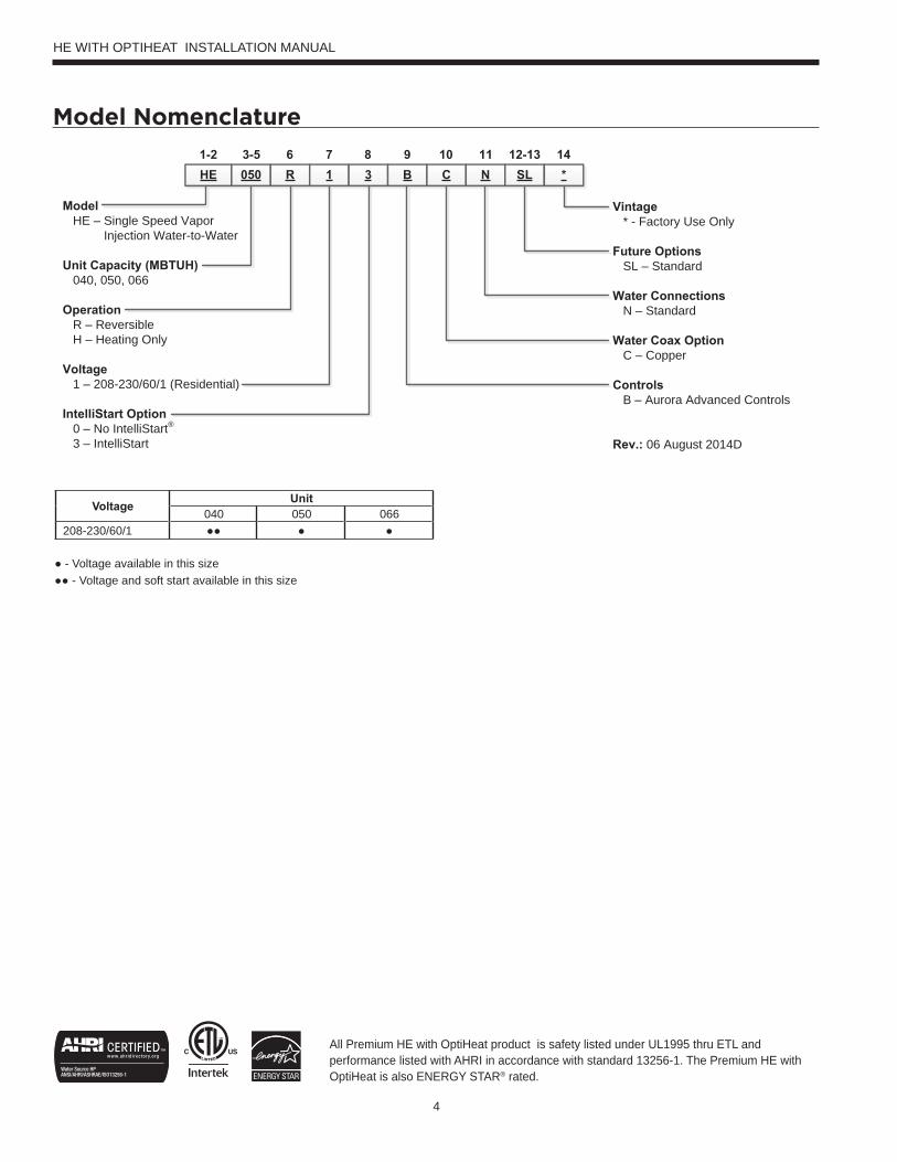
Model Nomenclature
HE WITH OPTIHEAT INSTALLATION MANUAL
HE 050 R 1 3 B C N SL *1-2 3-5 6 7 8 9 10 11 12-13 14
ModelHE – Single Speed Vapor
Injection Water-to-Water
Unit Capacity (MBTUH)040, 050, 066
OperationR – ReversibleH – Heating Only
Voltage1 – 208-230/60/1 (Residential)
IntelliStart Option0 – No IntelliStart®
3 – IntelliStart
Vintage* - Factory Use Only
Future OptionsSL – Standard
Water ConnectionsN – Standard
Water Coax OptionC – Copper
ControlsB – Aurora Advanced Controls
Rev.: 06 August 2014D
Voltage Unit040 050 066
208-230/60/1 ●● ● ● ● - Voltage available in this size ●● - Voltage and soft start available in this size
All Premium HE with OptiHeat product is safety listed under UL1995 thru ETL and performance listed with AHRI in accordance with standard 13256-1. The Premium HE with OptiHeat is also ENERGY STAR® rated.
5
General Installation InformationSafety ConsiderationsInstalling and servicing air conditioning and heating equipment can be hazardous due to system pressure and electrical components. Only trained and qualified service personnel should install, repair or service heating and air conditioning equipment. When working on heating and air conditioning equipment, observe precautions in the literature, tags and labels attached to the unit and other safety precautions that may apply.
Follow all safety codes. Wear safety glasses and work gloves. Use quenching cloth for brazing operations. Have fire extinguisher available for all brazing operations.
NOTE: Before installing, check voltage of unit(s) to ensure proper voltage.
WARNING: Before performing service or maintenance operations on the system, turn off main power switches to the unit. Electrical shock could cause serious personal injury.
WARNING: This heat pump is capable of producing hot water up to 150°F. All exposed piping surfaces shall be insulated to prevent serious personal injury that can occur from touching water piping.
ApplicationUnits are not intended for heating domestic (potable) water or swimming pools by direct coupling. If used for this type of application, a secondary heat exchanger must be used.
Moving and StorageMove units in the normal “Up” orientation as indicated by the labels on the unit packaging. When the equipment is received, all items should be carefully checked against the bill of lading to ensure that all crates and cartons have been received in good condition. Examine units for shipping damage, removing unit packaging if necessary to properly inspect unit. Units in question should also be internally inspected. If any damage is observed, the carrier should make the proper notation on delivery receipt acknowledging the damage. Units are to be stored in a location that provides adequate protection from dirt, debris and moisture.
WARNING: To avoid equipment damage, do not leave the system filled in a building without heat during cold weather, unless adequate freeze protection levels of antifreeze are used. Heat exchangers do not fully drain and will freeze unless protected, causing permanent damage.
Unit LocationProvide sufficient room to make water and electrical connections. If the unit is located in a confined space, provisions must be made for unit servicing. Locate the unit in an indoor area that allows easy removal of the access panels and has enough space for service personnel to perform maintenance or repair. These units are not approved for outdoor installation and, therefore, must be installed inside the structure being conditioned. Do not locate units in areas subject to freezing conditions.
WARNING: Do not store or install units in corrosive environments or in locations subject to temperature or humidity extremes (e.g. attics, garages, rooftops, etc.). Corrosive conditions and high temperature or humidity can significantly reduce performance, reliability, and service life.
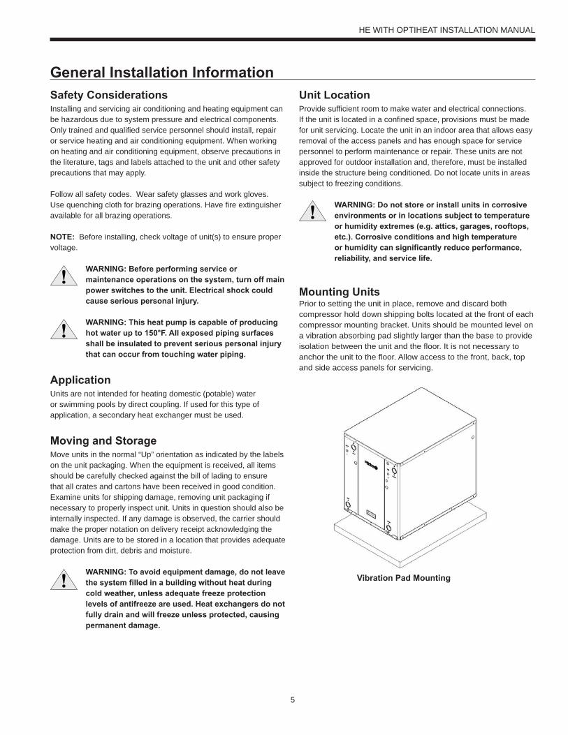
Mounting UnitsPrior to setting the unit in place, remove and discard both compressor hold down shipping bolts located at the front of each compressor mounting bracket. Units should be mounted level on a vibration absorbing pad slightly larger than the base to provide isolation between the unit and the floor. It is not necessary to anchor the unit to the floor. Allow access to the front, back, top and side access panels for servicing.
Vibration Pad Mounting
HE WITH OPTIHEAT INSTALLATION MANUAL
6
water flow and pressure drop information). Normally about 3 GPM flow rate per ton of cooling capacity (2.25 GPM per ton minimum) is needed. Both source as well as load fluid piping must be at least as large as the unit connections on the heat pump (larger on long runs).
Never use flexible hoses of a smaller inside diameter than that of the water connection on the unit and limit hose length to 10 ft. per connection. Check carefully for water leaks.
CAUTION: Water piping exposed to outside temperature may be subject to freezing.
Open Loop Well Water SystemsAlways maintain water pressure in the heat exchanger by placing water control valves at the outlet of the unit. Use a closed bladder type expansion tank to minimize mineral deposits. Ensure proper water flow through the unit by checking pressure drop across the heat exchanger and comparing it to the figures in the pressure drop table. Normally, about 2 GPM flow rate per ton of cooling capacity is needed in open loop systems, (1.5 GPM per ton minimum if entering source temperature is above 50°F [10°C].
Some water control valves draw their power directly from the unit’s 24V transformer and can overload and possibly burn out the transformer. Check total VA draw of the water valve(s) and ensure it is under 40 VA.
Discharge water from a heat pump can be disposed of in various ways depending on local building codes (i.e. recharge well, storm sewer, drain field, adjacent stream or pond, etc.). Most local codes restrict the use of sanitary sewer for disposal. Consult your local building and zoning departments to ensure compliance in your area.
GeneralEach unit is equipped with captive FPT water connections to eliminate ‘egg-shaping’ from use of a backup wrench. For making the water connections to the unit, a Teflon tape thread sealant is recommended to minimize internal fouling of the piping. Do not over tighten connections. All supply and return water piping should be insulated to prevent excess condensation from forming on the water lines.
NOTE: Units are factory run-tested using propyleneglycol. Prior to connecting piping to unit, thoroughly flush heat exchangers.
The piping installation should provide service personnel with the ability to measure water temperatures and pressures. The water lines should be routed so as not to interfere with access to the unit. The use of a short length of high pressure hose with a swivel type fitting may simplify the connections and prevent vibration. Optional stainless steel hose kits are available as an accessory item.
Before final connection to the unit, the supply and return hose kits must be connected, and the system flushed to remove dirt, piping chips and other foreign material. Normally, a combination balancing and close-off (ball) valve is installed at the return, and a rated gate or ball valve is installed at the supply. The return valve can be adjusted to obtain the proper water flow. The valves allow the unit to be removed for servicing.
The proper water flow must be delivered to each unit whenever the unit heats or cools. To assure proper flow, the use of pressure/temperature ports is recommended to determine the flow rate. These ports should be located adjacent to the supply and return connections on the unit. The proper flow rate cannot be accurately set without measuring the water pressure drop through the refrigerant-to-water heat exchanger (See Pressure Drop Table for
Field Connected Water Piping
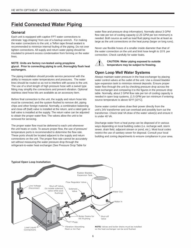
Line VoltageDisconnect
Load LiquidConnections
Water Out
Water In
Rubber BladderExpansion Tank
SolenoidValve
Flow Regulator Valve
Shut-off Valve(to isolate solenoid
valve while acidflushing)
Boiler Drains forHX Flushing
Shut-offValve
Vibration AbsorbingMesh or Air Pad
P/T Plugs
NOTE: Valves and boiler drains must be installedso the heat exchanger can be acid flushed.
Typical Open Loop Installation
HE WITH OPTIHEAT INSTALLATION MANUAL
7
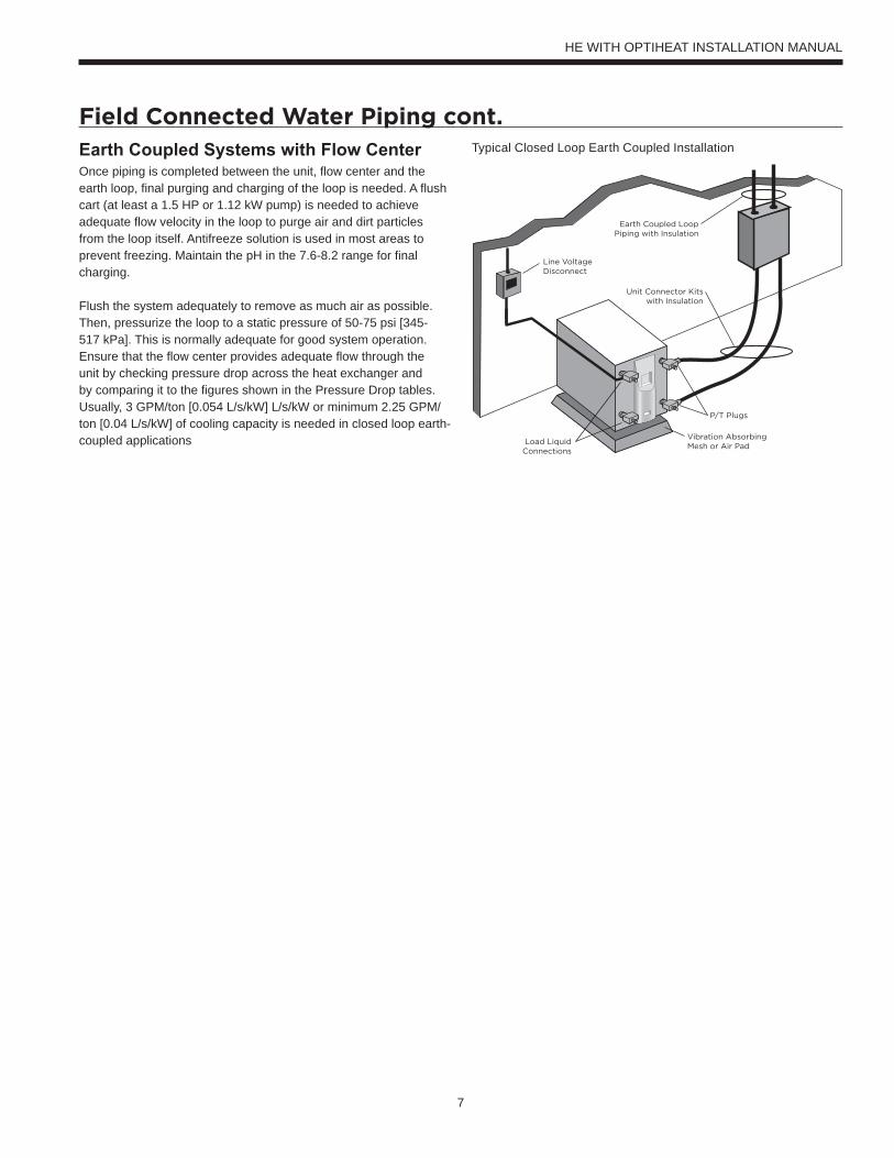
Field Connected Water Piping cont.Earth Coupled Systems with Flow CenterOnce piping is completed between the unit, flow center and the earth loop, final purging and charging of the loop is needed. A flush cart (at least a 1.5 HP or 1.12 kW pump) is needed to achieve adequate flow velocity in the loop to purge air and dirt particles from the loop itself. Antifreeze solution is used in most areas to prevent freezing. Maintain the pH in the 7.6-8.2 range for final charging.
Flush the system adequately to remove as much air as possible. Then, pressurize the loop to a static pressure of 50-75 psi [345-517 kPa]. This is normally adequate for good system operation. Ensure that the flow center provides adequate flow through the unit by checking pressure drop across the heat exchanger and by comparing it to the figures shown in the Pressure Drop tables. Usually, 3 GPM/ton [0.054 L/s/kW] L/s/kW or minimum 2.25 GPM/ton [0.04 L/s/kW] of cooling capacity is needed in closed loop earth-coupled applications
Typical Closed Loop Earth Coupled Installation
Line VoltageDisconnect
Load LiquidConnections
Vibration AbsorbingMesh or Air Pad
P/T Plugs
Unit Connector Kitswith Insulation
Earth Coupled LoopPiping with Insulation
HE WITH OPTIHEAT INSTALLATION MANUAL
8
Hydronic Section
HE WITH OPTIHEAT INSTALLATION MANUAL
General guidelines are shown below for component selection and design/installation criteria for the piping system. Local codes supersede any recommendations in this manual.
Shut Off/Flow Regulation ValvesUse full port ball valves or gate valves for component isolation. If valves are going to be used frequently, ball valves are recommended. Globe valves are designed for flow regulation. Always install globe valves in the correct direction (fluid should enter through the lower body chamber).
Check valvesSwing check valves must be installed in the horizontal position with the bonnet of the valve upright. Spring check valves can be mounted in any position. A flow check valve is required to prevent thermo-siphoning (or gravity flow) when the circulator pump is off or when there are two circulators on the same system.
Storage (Buffer) TankA buffer tank is required for all hydronic heating systems using HE Heat Pumps with OptiHeat. The tank should be sized to provide 2 gallons of storage capacity for every one thousand Btuh’s of nominal heat pump capacity.
Pressure Relief ValveMost codes require the use of a pressure relief valve if a closed loop heat source can be isolated by valves. Even if local code does not require this device, the manufacturer recommends its installation. If the pressure relief valve in the buffer tank is not already rated at 30 psi (207 kPa) maximum pressure, one must be installed. The pressure relief valve should be tested at start up for operation. Note that the waste pipe must be at least the same diameter as the valve outlet (never reduce), and valves may not be added to this pipe. The bottom of the pipe must terminate at least 6” (15 cm) above the floor. If the piping is connected to a drain, there must be an air gap.
Backflow Prevention Check ValvesMost codes require backflow prevention check valves. Note that a single check valve is not equal to a backflow prevention check valve. Even if local code does not require this device, the manufacturer recommends its installation. This is particularly important if the system will use antifreeze.
Pressure Reducing Valves or Feed Water ValvesThis valve lowers the pressure from the make-up water line to the system. Most are adjustable and directional. A “fast fill” valve is required for initial filling of the system. Some have screens, which must be cleaned after the initial filling. If there is a restriction in the screen, the system could go to 0 psi (0 kPa), potentially causing pumps(s) failure. A valve should be installed on each side of the pressure reducing valve for servicing. Both valves should have tags reading “Do not shut this valve under normal operation – service valve only.”
Expansion TanksExpansion tanks are required on hydronic systems to help absorb the pressure swings as the temperature in the system fluctuates.
Elbows/TeesLong radius elbows or two 45° elbows will lower pressure drop. Standard tees have a greater restriction on the “T” portion than tees designed with angled outlet ports.
AntifreezeAntifreeze is required if any of the piping system is located in areas subject to freezing.
Dielectric UnionsDielectric unions are recommended whenever connecting two dissimilar metals together to prevent electro-galvanic corrosion.
When using the various types of hydronic heat distribution systems, the temperature limits of the geothermal system must be a major consideration. In new construction, the distribution system can easily be designed with the temperature limits in mind. In retrofits, care must be taken to address the operating temperature limits of the existing distribution system. The maximum storage tank temperature for the HE with OptiHeat is 150°F (65°C). Typical in floor radiant systems require much lower temperatures, typically 100°-115°F, which is ideal for the HE with OptiHeat.
Open the screw 2 turns only in the end of the pump motor (if Grundfos® pumps are used) to allow trapped air to be discharged and to ensure the motor housing has been flooded.
9
Hydronic Section cont.
Thermostat
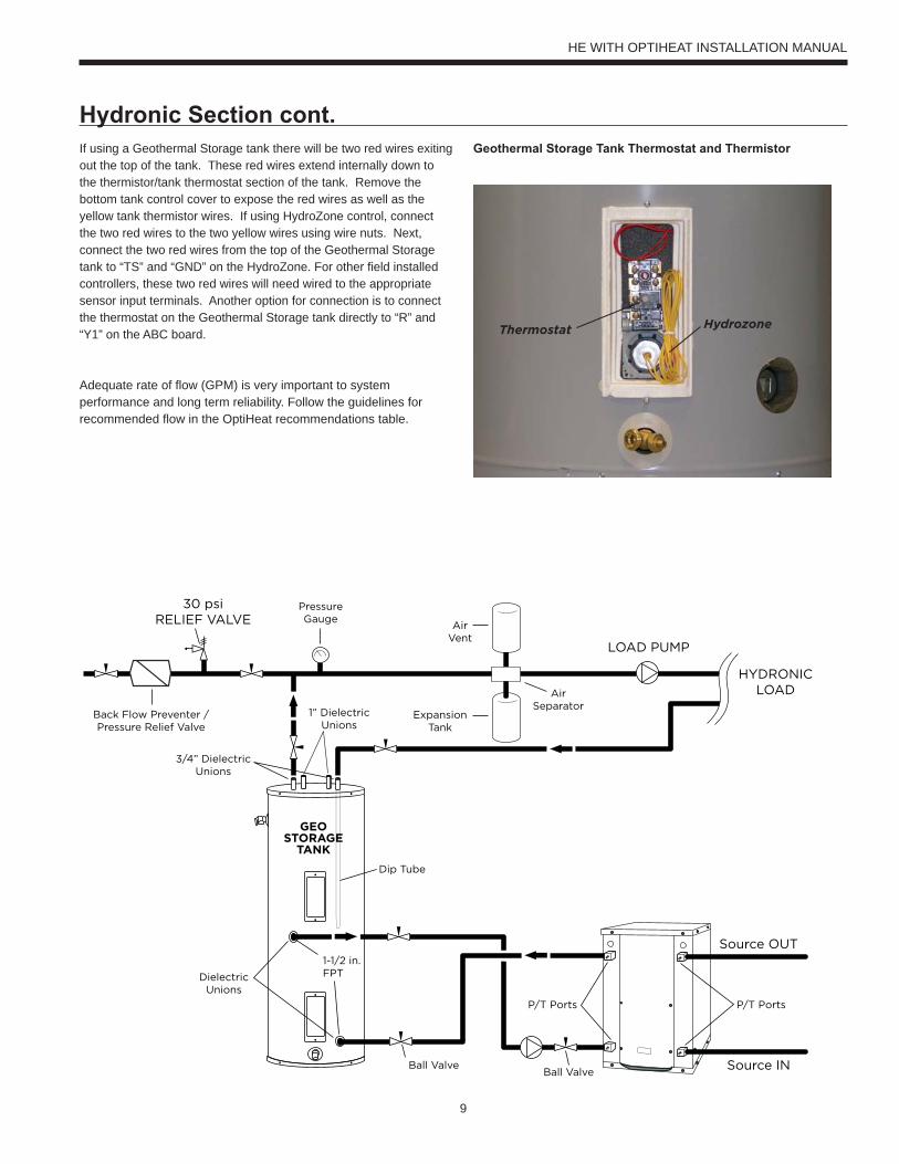
If using a Geothermal Storage tank there will be two red wires exiting out the top of the tank. These red wires extend internally down to the thermistor/tank thermostat section of the tank. Remove the bottom tank control cover to expose the red wires as well as the yellow tank thermistor wires. If using HydroZone control, connect the two red wires to the two yellow wires using wire nuts. Next, connect the two red wires from the top of the Geothermal Storage tank to “TS” and “GND” on the HydroZone. For other field installed controllers, these two red wires will need wired to the appropriate sensor input terminals. Another option for connection is to connect the thermostat on the Geothermal Storage tank directly to “R” and “Y1” on the ABC board.
Adequate rate of flow (GPM) is very important to system performance and long term reliability. Follow the guidelines for recommended flow in the OptiHeat recommendations table.
Geothermal Storage Tank Thermostat and Thermistor
LOAD PUMP
HYDRONICLOAD
Source OUT
P/T PortsP/T Ports
Ball Valve
DielectricUnions
3/4” DielectricUnions
1” DielectricUnions
1-1/2 in.FPT
ExpansionTank
AirVent
PressureGauge
30 psiRELIEF VALVE
AirSeparator
Back Flow Preventer /Pressure Relief Valve
Source IN
GEOSTORAGE
TANK
Dip Tube
Ball Valve
HE WITH OPTIHEAT INSTALLATION MANUAL
Hydrozone
10
Accessories and OptionsIntelliStart (Model 040 Only)IntelliStart is a single phase compressor soft starter which reduces the normal start current (LRA) by 60-70%. It should be used in applications that require low starting amps, reduced compressor start-up noise, off-grid, and improved start-up behavior. IntelliStart is available as a factory installed option or a field installed kit. IntelliStart is available on 208-230/60/1 voltage.
Water Connection Kits (Field Installed)Water connection kits are available to facilitate loop side and load side water connections.• MA4FPT - Forged brass 1" MPT x 1" FPT square street elbow with
P/T plug for NEW040 water side connections• MA5FPT - Forged brass 1.25" MPT x 1.25" FPT square
street elbow with P/T plug for NEW050-NEW066 water side connections
• 2-HVAC-1x24 - 1 inch x 24 inch stainless steel braided hose kit• 2-HVAC-1 1/4x24 - 1 1⁄4 inch x 24 inch stainless steel braided
hose kit
Earth Loop Pump Kit (Field Installed)A specially designed one or two-pump module provides all liquid flow, fill and connection requirements for independent single unit systems (230/60/1 only). The one-pump module (FC1-FPT or FC1-GL) is capable of 25 feet of head at 12.0 GPM, while the two-pump module (FC2-FPT or FC1-GL) is capable of 50 feet of head at 12.0 GPM.
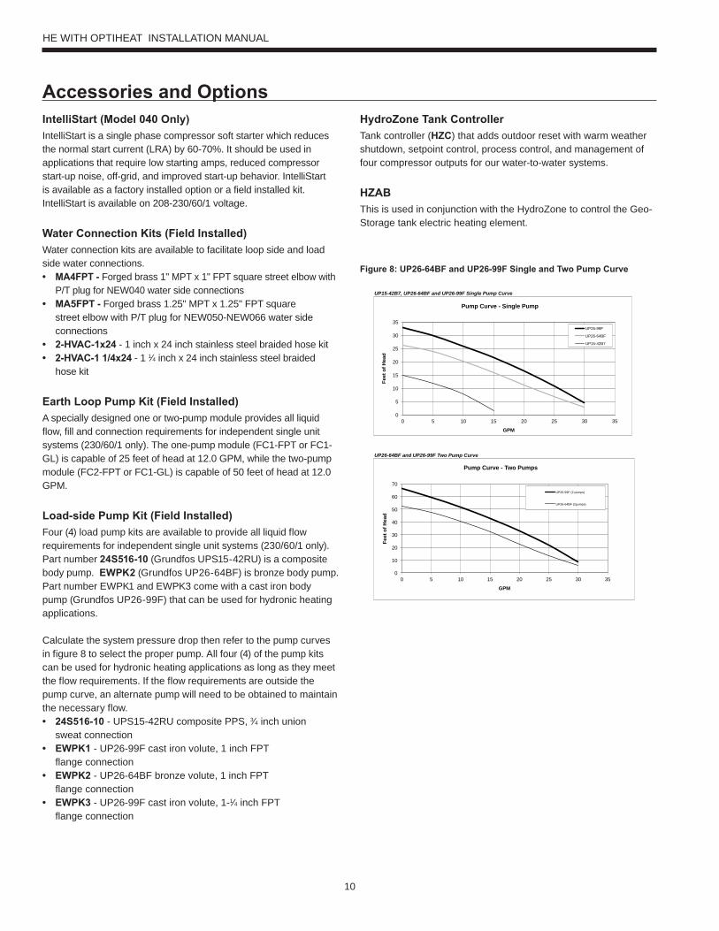
Load-side Pump Kit (Field Installed)Four (4) load pump kits are available to provide all liquid flow requirements for independent single unit systems (230/60/1 only). Part number 24S516-10 (Grundfos UPS15-42RU) is a composite body pump. EWPK2 (Grundfos UP26-64BF) is bronze body pump. Part number EWPK1 and EWPK3 come with a cast iron body pump (Grundfos UP26-99F) that can be used for hydronic heating applications.
Calculate the system pressure drop then refer to the pump curves in figure 8 to select the proper pump. All four (4) of the pump kits can be used for hydronic heating applications as long as they meet the flow requirements. If the flow requirements are outside the pump curve, an alternate pump will need to be obtained to maintain the necessary flow.• 24S516-10 - UPS15-42RU composite PPS, 3⁄4 inch union
sweat connection• EWPK1 - UP26-99F cast iron volute, 1 inch FPT
flange connection• EWPK2 - UP26-64BF bronze volute, 1 inch FPT
flange connection• EWPK3 - UP26-99F cast iron volute, 1-1⁄4 inch FPT
flange connection
Figure 8: UP26-64BF and UP26-99F Single and Two Pump Curve
HydroZone Tank ControllerTank controller (HZC) that adds outdoor reset with warm weather shutdown, setpoint control, process control, and management of four compressor outputs for our water-to-water systems.
HZABThis is used in conjunction with the HydroZone to control the Geo-Storage tank electric heating element.
UP15-42B7, UP26-64BF and UP26-99F Single Pump Curve
UP26-64BF and UP26-99F Two Pump Curve
0
5
10
15
20
25
30
35
0 5 10 15 20 25 30 35
Feet
of H
ead
GPM
Pump Curve - Single Pump
UP26-99F
UP26-64BF
UP15-42B7
0
10
20
30
40
50
60
70
0 5 10 15 20 25 30 35
Feet
of H
ead
GPM
Pump Curve - Two Pumps
UP26-99F (2 pumps)
UP26-64BF (2pumps)
HE WITH OPTIHEAT INSTALLATION MANUAL
11
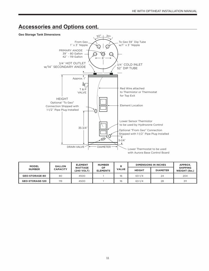
30° 30°
To Geo 59˝ Dip Tubew/1˝ x 3˝ Nipple
Approx. 1˝
T & PVALVE
From Geo1˝ x 3˝ Nipple
PRIMARY ANODE39˝ - 80 Gallon42˝ - 119 Gallon
3/4˝ COLD INLET52˝ DIP TUBE
3/4˝ HOT OUTLETw/14˝ SECONDARY ANODE
HEIGHTOptional “To Geo”
Connection Shipped with
1-1/2˝ Pipe Plug Installed
Element Location
Red Wire attached
to Thermistor or Thermostat
for Top Exit
Lower Sensor Thermistor
to be used by Hydrozone Control
Optional “From Geo” Connection
Shipped with 1-1/2˝ Pipe Plug Installed
DIAMETER
8˝
5-1/4˝
35-3/4˝
Lower Thermostat to be used
with Aurora Base Control Board
DRAIN VALVE
MODELNUMBER
GALLONCAPACITY
ELEMENTWATTAGE
(240 VOLT)
NUMBEROF
ELEMENTS
RVALUE
DIMENSIONS IN INCHES APPROX.SHIPPING
WEIGHT (lbs.)HEIGHT DIAMETER
GEO-STORAGE-80 80 4500 1 16 63-1/4 24 204
GEO-STORAGE-120 119 4500 1 16 63-1/4 28 311
Accessories and Options cont.Geo Storage Tank Dimensions
HE WITH OPTIHEAT INSTALLATION MANUAL
12
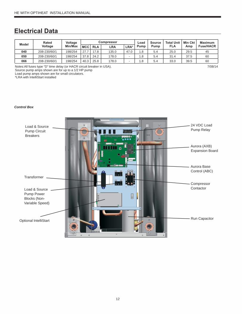
Control Box
Electrical Data
Model RatedVoltage
VoltageMin/Max
Compressor LoadPump
SourcePump
Total UnitFLA
Min CktAmp
MaximumFuse/HACRMCC RLA LRA LRA*
040 208-230/60/1 198/254 27.7 17.8 135.0 47.0 1.8 5.4 25.0 29.5 45050 208-230/60/1 198/254 37.8 24.2 178.0 - 1.8 5.4 31.4 37.5 60066 208-230/60/1 198/254 40.3 25.8 178.0 - 1.8 5.4 33.0 39.5 60
Notes:All fuses type “D” time delay (or HACR circuit breaker in USA). 7/08/14Source pump amps shown are for up to a 1/2 HP pumpLoad pump amps shown are for small circulators.*LRA with IntelliStart installed
Load & Source Pump Circuit Breakers
Transformer
Load & Source Pump Power Blocks (Non-Variable Speed)
Optional IntelliStart
24 VDC Load Pump Relay
Aurora (AXB) Expansion Board
Aurora Base Control (ABC)
Compressor Contactor
Run Capacitor
HE WITH OPTIHEAT INSTALLATION MANUAL
13
Electrical Data cont.208 Volt OperationAll 208-230 volt units are factory wired for 230 volt operation. To convert the unit from a 230V unit to a 208V unit follow these steps:
1. Remove the blue transformer wire from terminal L2 on the compressor contactor and secure the wire taking care to insulate the end with electrical tape.
2. Locate the red transformer wire and connect it to the L2 terminal of the compressor contactor.
ElectricalBe sure the available power is the same voltage and phase as that shown on the unit serial plate. Line and low voltage wiring must be done in accordance with local codes or the National Electric Code, whichever is applicable. Refer to the Electrical Data table for wire and fuse or circuit breaker sizing information.
Flow Center Pump Connection (208-230/60/1)Two internal terminal block connections with 1/4-inch spade connectors are provided; one for the load pump and one for the source pump. The source pump directly connects to the 5A circuit breakers for the source pump. The load pump directly connects to the 5A circuit breakers for the load pump. This section is not used for variable speed pumps.
Control Box RelocationThe control box can be installed on the rear of the unit. To relocate the control box, follow the procedures below.
1. Remove all power sources to the unit.2. Remove the unit’s top panel.3. Cut all plastic wire ties to the following:
a) High pressure switch (black wires) b) Low pressure switch (blue wires)
c) Freeze sensing d) Load temperature sensor e) Compressor wires4. Remove the four screws from the control box.5. Relocate the control box to opposite end of the unit.6. Using the screws removed in step 4 above, reattach the control
box.7. Secure all wires so they do not come in contact with refrigerant
lines.8. Replace the top of the unit.9. Replace both access panels.10. Reapply power sources.
Unit StartupBefore Powering UnitCheck the following:• High voltage wiring is correct and matches the nameplate.• Fuses, breakers and wire size are correct.• Piping is completed and water system has been cleaned and
flushed.• Air is purged from the closed loop system.• Isolation valves are open and loop water control valves or loop
pumps are wired.• Service/access panels are in place.
HE WITH OPTIHEAT INSTALLATION MANUAL
14
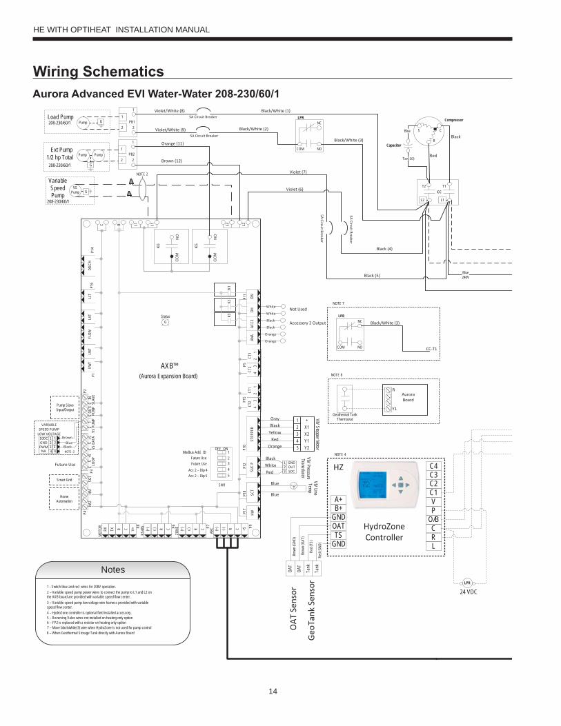
Wiring Schematics
Blue240V
CCT2 T1
Compressor
C
R
SBlue
L1L2
Tan(10)
Capacitor
HW HW
Black
Black
Orange
Orange
SCT
P8
MOTO
R P6
RS48
5 P7
ZONE P9
ABC
STEP
PER
ANA
ACC2
DHDI
V
NO
CO
M
K6
NO
CO
M
K5
C L1 L1 L2 L2P1
2P1
0P5
P11
CR(-)(+) CR(-)(+) CR(-)(+)
P4P2
K1K2
K3
HA2
HA1
SGI
LOOP
VS D
ATA
VS P
UMP
PUMP
SLAV
EP3
R
V+CRTXRX +5
P14
LLT
P1LA
TFL
OWLW
TEW
T
CT2
43
CT2
43
CT1
21
CT1
21
StatusG
DISC
HP1
6
P17
P18
P15
(Aurora Expansion Board)AXB™
SW1
Modbus Add. IDFuture Use
12345
ONOFF
Future UseAcc 2 – Dip 4Acc 2 – Dip 5
CS
+5C
S+5
21
CC
INOU
T
T
VIV Line Temp
1234
+X1X2Y1
5 Y2
VIV Stepper Motor5A Circuit Breaker
5A Circuit Breaker
1
2PB2
2
1
208-230/60/1
Pump
G
PumpExt Pump
1/2 hp Total
Variable Speed Pump
208-230/60/1
VSPump G
NOTE 2
Black
OrangeRed
Yellow
Gray
Blue
Blue
GNDOUT5DC
123SU
C P White
Red
Black VIV Pressure Transducer
Pump Slave Input/Output
Smart Grid
Home Automation
NOTE: 3
Blue321
4
10DCGNDPWM
123
NA 4
VARIABLE SPEED PUMP
LOW VOLTAGEBrown
Black
Future Use
Accessory 2 Output
1
2PB1
2
1208-230/60/1 GPumpLoad Pump
5A Circuit Breaker
5A Circuit Breaker
OAT
Sen
sor
Geo
Tank
Sen
sor
OAT
OAT
Tank
Tank
Red (
GND)
Red (
TS)
Brow
n (OA
T)
Brow
n (GN
D)
HydroZone Controller
GNDTS
OATGNDB+A+
HZ
RC
O/BPV
C1C2C3C4
L
NOTE 4
Notes1 - Switch blue and red wires for 208V operation. 2 – Variable speed pump power wires to connect the pump to L1 and L2 on the AXB board are provided with variable speed flow center.3 – Variable speed pump low voltage wire harness provided with variable speed flow center.4 – HydroZone controller is optional field installed accessory.
Black
Red
White
WhiteNot Used
Violet/White (8)
Violet/White (9) Black/White (2)
Black/White (1)
Violet (7)
Violet (6)
Black (4)
Black (5)
Orange (11)
Brown (12)
5 – Reversing Valve wires not installed on heating only option
LPR
LPR
NO
NC
COM
Black/White (3)
24 VDC
6 – FP2 is replaced with a resistor on heating only option
LPR
NO
NC
COM
Black/White (3)
CC-T1
NOTE 7
7 – Move black/white(3) wire when HydroZone is not used for pump control
Geothermal Tank Thermostat
Y1
NOTE 8
RAurora Board
8 – When Geothermal Storage Tank directly with Aurora Board
Aurora Advanced EVI Water-Water 208-230/60/1
HE WITH OPTIHEAT INSTALLATION MANUAL
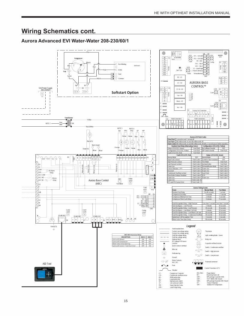
15
Wiring Schematics cont.
Transformer
24V
CC
HP
Black
Black
Blue
Blue
LP
T
Yellow
Yellow
FP1
Black(15)
Violet(14)
Green(13)
Black/White
YellowRed208V
G
208-230/60/1Unit Power Supply
AID Tool
DESCRIPTION SW2-4 SW2-5Cycle with Blower ON ONCycle with Compressor OFF OFFWater Valve Slow Opening ON OFFCycle with Comm. T-stat Hum Cmd OFF ON
ABC SW2 Accessory Relay
Aurora LED Flash Codes
Status LED (LED3, Green)
Status LED (LED1, Green)Configuration LED (LED2, Yellow)Fault LED (LED3, Red)
Random Start Delay (Alternating Colors)Fast FlashFast FlashFast Flash
1 second on and 1 second off100 milliseconds on and 100 milliseconds off100 milliseconds on and 400 milliseconds off with a 2 second pause before repeating
Slow FlashFast FlashFlash Code
Normal ModeControl is Non-FunctionalTest ModeLockout ActiveDehumidification ModeFuture UseFuture UseLoad ShedESD
OFFON
Slow FlashFast Flash
Flash Code 2Flash Code 3
Flash Code 6
Flash Code 4Flash Code 5
Future Use Flash Code 7
Configuration LED (LED2, Yellow)No Software Overide OFFDIP Switch Overide Slow Flash
Fault LED (LED1, Red)Normal ModeInput Fault LockoutHigh Pressure LockoutLow Pressure LockoutFuture UseFreeze Detection – FP1ReservedCondensate Overflow LockoutOver/Under Voltage ShutdownFuture UseFuture UseFP1 and FP2 Sensor Error
Flash Code 1OFF
Flash Code 2Flash Code 3Flash Code 4Flash Code 5
Flash Code 8
Flash Code 6Flash Code 7
Flash Code 9Flash Code 10Flash Code 11
CFM
P13
P4
SW1
P5JW2
P9
LO
O/B
Y2WDH
P8 P7
RS485 NET RS485 NET
P6
RS485 EXP
P3
SW2
On
Future Use L Output Type
CC – Dual/SingleAcc – Dip 5Acc – Dip 4
RV – B/OFP2 – 15°F/30°FFP1 – 15°F/30°F
Com1LED5
Com2LED5
Test Mode
F1-3A
P1
C
PWM
12345678
ALMALGACC COMACC NOACC NC
RC
GY1
EH2CEH1CCOC R - +C R - +
Off
FaultLED1
R
StatusLED3
ConfigLED2
CC2 CC F C R F FG CC CCGCC2HI
CC2LO
CC2G REV REV FP1 FP1 FP2 FP2 LPS LPS HPS HPS
Aurora Base Control(ABC)
K1-RV Relay
K2-CC Relay
K3-CC2 Relay
K4-Fan RelayK5-Alarm Relay
K6-Acc Relay
F
R
C
CCGY1C
R
ESLS
P2
EH1
YG G
G
CC2
Facto
ry
Fault
ALG
ALMLSES ACC
c
Status
AURORA BASE CONTROL™
RV – K1
CC2
CC – K2
CC Hi – K3
Fan – K4
Alarm – K5
Acc – K6
ACC
noAC
C nc
O/BCRLO G Y1 Y2 W DH
3A-F
use
O/BCRLO G Y1 Y2 W DH
LOG
HICCGCCFGFR
HPHPLP
FP2FP2FP1
REVREV
CFM
PWM
ECM PWM
Facto
ry
Factory Fan Connection
R R
CC
C
CR(-)(+)
RS 48
5
EH2C
EH1C
CO
(+)(-)RCRS
485 E
xpFa
ctory
Com1
Com2
Config
G
G
G
YR
SW1 Test
FP1 – 15oF/30oF
JW2 - Alarm
P11
P5
P2 P1
P8
P7
P9
P6
P3
SW2
P13P4 FP2 – 15oF/30oF
RV – B/OACC – Dip 4ACC – Dip 5
CC – Dual/Single L – Pulse/Continuous
Reheat/Normal
Facto
ry Us
e
Field ConnectionsField Connections
C
LP
FP1
F
CC
G
Y1
12345678
Off On
N/A
RS48
5 NET
EH1LED1 LED2
LED3
LED4
LED5
T2 T1
Compressor
C
R
SBlue
Tan(6)
Cap
Run Winding
Active
Start
Common
SoftstartRed
Pink
Black
Blue
CCT2 T1
L1L2 Softstart Option
NOTE 1
Black
BlueBlue
Not Used
Orange
Orange
T
Yellow
Yellow
FP2
RV
RVNOTE 5
Current Transducer (CT)
Thermistor
Light emitting diode - Green
Relay coil
Capacitor w/ bleed resistor
Switch - Condensate overflow
Switch - High pressure
Switch - Low pressure
Polarized connector
Factory Low voltage wiringFactory Line voltage wiringField low voltage wiringField line voltage wiringOptional blockDC Voltage PCB tracesJunctionQuick connect terminal
Wire nut
Field wire lug
Ground
Fuse
CC -CO -K6 -K5 -
FP -HP - LP -
PB1, PB2 - RV -SW1 -SW1 -SW2 -
Compressor ContactorCondensate overflow sensorDHW pump relayLoop pump relay
Freeze ProtectionHigh pressure switchLow pressure switch
Power blocksReversing Valve coilDIP package 5 position AXBTEST MODE ABC BoardDIP package 8 position ABC Board
Legend
Relay Contacts-N.O., N.C.
G
T
132P
L1
Breaker
Vapor Injection Valve VIV - LPR - Load Pump Relay
OAT - Outdoor Air Temperature
Field Installed Item
Event Normal Mode Test ModeRandom Start DelayCompressor On DelayCompressor Minimum On TimeCompressor Short Cycle Delay
Fault Recognition Delay – High PressureStart-Up Bypass – Low PressureFault Recognition Delay – Low PressureStart-Up Bypass – Low Water Coil LimitFault Recognition Delay – Low Water Coil LimitFault Recognition Delay – Condensate OverflowHydroZone Call Recognition Time
Less than 1 second
5 to 80 seconds 1 second5 seconds < 1 second
Less than 1 second
2 minutes 5 seconds4 minutes 15 seconds
2 minutes
2 minutes
30 seconds30 seconds 30 seconds
30 seconds30 seconds
30 seconds30 seconds30 seconds
2 seconds 2 seconds
Aurora Timing Events
Water Valve Slow Open Delay 90 seconds 90 seconds
NOTE 6
Aurora Advanced EVI Water-Water 208-230/60/1
HE WITH OPTIHEAT INSTALLATION MANUAL
16
Aurora Control Features Description Aurora 'Advanced'
Microprocessor Compressor Control Microprocessor control of compressor for timings with FP1, HP, LP, Condensate, assignable Acc relay •
Advanced Microprocessor Features Smart Grid, Home Automation Alarm Inputs, and Accessory2 Relay (HRV/ERV) •
Advanced Speed Pump Control Microprocessor and separate power relay for loop pump and inline circuit breakers and loop pump slaving. •
Variable Speed Pump Capable of setup, monitoring and controlling a variable speed flow center. •
Smart Grid/Utility Input Allows simple input to externally enable of occupied/unoccupied mode for basic utility time of use programs. Dry Contact x1
Home Automation Alarm InputAllows simple input to signal sump, security, or smoke/CO sensor alarms from other home automation or security systems. The two inputs can be field configured to a number of options and logic.
Dry Contactx2
HAN/Smart Grid Com(AWL and Portal) Kit
Allows direct communication of the Aurora to Smart Meters, Home Automation Network and Internet. Optional AWL
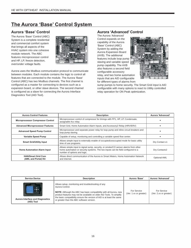
Aurora ‘Base’ ControlThe Aurora ‘Base’ Control (ABC) System is a complete residential and commercial comfort system that brings all aspects of the HVAC system into one cohesive module network. The ABC features microprocessor control and HP, LP, freeze detection, over/under voltage faults.
Aurora uses the Modbus communication protocol to communicate between modules. Each module contains the logic to control all features that are connected to the module. The Aurora ‘Base’ Control (ABC) has two Modbus channels. The first channel is configured as a master for connecting to devices such as a expansion board, or other slave devices. The second channel is configured as a slave for connecting the Aurora Interface Diagnostics Tool (AID Tool).
Aurora ‘Advanced’ ControlThe Aurora ‘Advanced’ Control expands on the capability of the Aurora ‘Base’ Control (ABC) System by adding the Aurora Expansion Board (AXB). The additional features include loop pump slaving and variable speed pump capability. The AXB also features a second field configurable accessory relay, and two home automation inputs that are AID configurable for different types of alarms from sump pumps to home security. The Smart Grid input is AID configurable with many options to react to Utility controlled relay operation for ON Peak optimization.
Service Device Description Aurora ‘Base’ Aurora 'Advanced'
Aurora Interface and Diagnostics (AID) Tool
Allows setup, monitoring and troubleshooting of anyAurora Control.
NOTE: Although the ABC has basic compatibility with all Aurora, new product features may not be available on older AID Tools. To simplify the basic compatibility ensure the version of AID is at least the same or greater than the ABC software version.
For Service(Ver. 1.xx or greater)
For Service(Ver. 2.xx or greater)
The Aurora ‘Base’ Control System
HE WITH OPTIHEAT INSTALLATION MANUAL
17
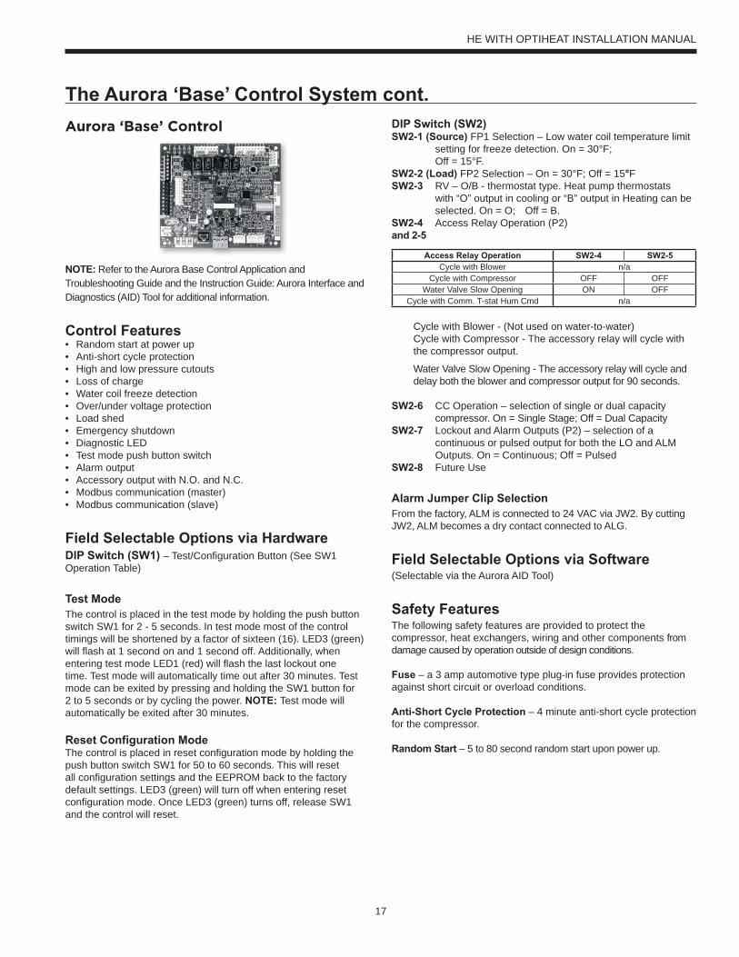
Aurora ‘Base’ Control
NOTE: Refer to the Aurora Base Control Application and Troubleshooting Guide and the Instruction Guide: Aurora Interface and Diagnostics (AID) Tool for additional information.
Control Features• Random start at power up• Anti-short cycle protection• High and low pressure cutouts• Loss of charge• Water coil freeze detection• Over/under voltage protection• Load shed• Emergency shutdown• Diagnostic LED• Test mode push button switch• Alarm output• Accessory output with N.O. and N.C.• Modbus communication (master)• Modbus communication (slave)
Field Selectable Options via HardwareDIP Switch (SW1) – Test/Configuration Button (See SW1 Operation Table)
Test ModeThe control is placed in the test mode by holding the push button switch SW1 for 2 - 5 seconds. In test mode most of the control timings will be shortened by a factor of sixteen (16). LED3 (green) will flash at 1 second on and 1 second off. Additionally, when entering test mode LED1 (red) will flash the last lockout one time. Test mode will automatically time out after 30 minutes. Test mode can be exited by pressing and holding the SW1 button for 2 to 5 seconds or by cycling the power. NOTE: Test mode will automatically be exited after 30 minutes.
Reset Configuration ModeThe control is placed in reset configuration mode by holding the push button switch SW1 for 50 to 60 seconds. This will reset all configuration settings and the EEPROM back to the factory default settings. LED3 (green) will turn off when entering reset configuration mode. Once LED3 (green) turns off, release SW1 and the control will reset.
DIP Switch (SW2) SW2-1 (Source) FP1 Selection – Low water coil temperature limit
setting for freeze detection. On = 30°F; Off = 15°F.SW2-2 (Load) FP2 Selection – On = 30°F; Off = 15°FSW2-3 RV – O/B - thermostat type. Heat pump thermostats
with “O” output in cooling or “B” output in Heating can be selected. On = O; Off = B.
SW2-4 Access Relay Operation (P2)and 2-5
Access Relay Operation SW2-4 SW2-5Cycle with Blower n/a
Cycle with Compressor OFF OFFWater Valve Slow Opening ON OFF
Cycle with Comm. T-stat Hum Cmd n/a
Cycle with Blower - (Not used on water-to-water)Cycle with Compressor - The accessory relay will cycle with the compressor output.
Water Valve Slow Opening - The accessory relay will cycle and delay both the blower and compressor output for 90 seconds.
SW2-6 CC Operation – selection of single or dual capacity compressor. On = Single Stage; Off = Dual Capacity
SW2-7 Lockout and Alarm Outputs (P2) – selection of a continuous or pulsed output for both the LO and ALM Outputs. On = Continuous; Off = Pulsed
SW2-8 Future Use
Alarm Jumper Clip SelectionFrom the factory, ALM is connected to 24 VAC via JW2. By cutting JW2, ALM becomes a dry contact connected to ALG.
Field Selectable Options via Software(Selectable via the Aurora AID Tool)
Safety FeaturesThe following safety features are provided to protect the compressor, heat exchangers, wiring and other components from damage caused by operation outside of design conditions.
Fuse – a 3 amp automotive type plug-in fuse provides protection against short circuit or overload conditions.
Anti-Short Cycle Protection – 4 minute anti-short cycle protectionfor the compressor.
Random Start – 5 to 80 second random start upon power up.
The Aurora ‘Base’ Control System cont.
HE WITH OPTIHEAT INSTALLATION MANUAL
18
Fault Retry – in the fault condition, the control will stage off the outputs and then “try again” to satisfy the thermostat Y input call. Once the thermostat input calls are satisfied, the control will continue on as if no fault occurred. If 3 consecutive faults occur without satisfying the thermostat Y input call, then the control will go to Lockout mode.
Lockout – The Alarm output (ALM) and Lockout output (L) will be turned on. The fault type identification display LED1 (Red) shall flash the fault code. To reset lockout conditions with SW2-8 On, thermostat inputs “Y1”, “Y2”, and “W” must be removed for at least 3 seconds. To reset lockout conditions with SW2-8 Off, thermostat inputs “Y1”, “Y2”, “W”, and “DH” must be removed for at least 3 seconds. Lockout may also be reset by turning power off for at least 30 seconds or by enabling the emergency shutdown input for at least 3 seconds.
High Pressure – fault is recognized when the Normally Closed High Pressure Switch, P4-9/10 opens, no matter how momentarily. The High Pressure Switch is electrically in series with the Compressor Contactor and serves as a hard-wired limit switch if an overpressure condition should occur.
Low Pressure - fault is recognized when the Normally Closed Low Pressure Switch, P4-7/8 is continuously open for 30 seconds. Closure of the LPS any time during the 30 second recognition time restarts the 30 second continuous open requirement. A continuously open LPS shall not be recognized during the 2 minute startup bypass time.
Loss of Charge – fault is recognized when the Normally Closed Low Pressure Switch, P4-7/8 is open prior to the compressor starting.
Freeze Detection (Source Coax) - set points shall be either 30°F or 15°F. When the thermistor temperature drops below the selected set point, the control shall begin counting down the 30 seconds delay. If the thermistor value rises above the selected set point, then the count should reset. The resistance value must remain below the selected set point for the entire length of the appropriate delay to be recognized as a fault. This fault will be ignored for the initial 2 minutes of the compressor run time.
Freeze Detection (Load Coax) - uses the FP2 input to protect against ice formation on the coax. The FP2 input will operate exactly like FP1 except that the set point is 30 degrees and is not field adjustable.
Over/Under Voltage Shutdown - An over/under voltage condition exists when the control voltage is outside the range of 18 VAC to 30 VAC. If the over/under voltage shutdown lasts for 15 minutes, the lockout and alarm relay will be energized. Over/under voltage shutdown is self-resetting in that if the voltage comes back within range of 18 VAC to 30 VAC for at least 0.5 seconds, then normal operation is restored.
Operation DescriptionPower Up - The unit will not operate until all the inputs and safety controls are checked for normal conditions. The unit has a 5 to 80 second random start delay at power up. Then the compressor has a 4 minute anti-short cycle delay after the random start delay.
Standby In standby mode, Y1, Y2, W, DH, and G are not active. Input O may be active. The blower and compressor will be off.
Heating OperationHeating, 1st Stage (Y1) - The compressor is energized 10 seconds after the Y1 input is received.
Cooling OperationIn all cooling operations, the reversing valve directly tracks the O input. Thus, anytime the O input is present, the reversing valve will be energized.
Cooling, 1st Stage (Y1, O) - The compressor is energized 10 seconds after the Y1 input is received.
Emergency Shutdown - Four (4) seconds after a valid ES input, P2-7 is present, all control outputs will be turned off and remain off until the emergency shutdown input is no longer present. The first time that the compressor is started after the control exits the emergency shutdown mode, there will be an anti-short cycle delay followed by a random start delay. Input must be tied to common to activate.
Load Shed - The LS input disables all outputs with the exception of the blower output. When the LS input has been cleared, the anti-short cycle timer and random start timer will be initiated. Input must be tied to common to activate.
The Aurora ‘Base’ Control System cont.
HE WITH OPTIHEAT INSTALLATION MANUAL

19
CC2
Facto
ry
Fault
ALG
ALMLSES ACC
c
Status
AuroraTM BaseControl
RV – K1
CC2
CC – K2
CC Hi – K3
Fan – K4
Alarm – K5
Acc – K6
ACC
noAC
C nc
O/BCRLO G Y1 Y2 W DH
3A-F
use
O/BCRLO G Y1 Y2 W DH
LOG
HICCGCCFGFR
HPHPLP
FP2FP2FP1
REVREV
CFM
PWM
ECM PWM
Facto
ry
Factory Fan Connection
R R
CC
C
CR(-)(+)
RS 48
5
EH2C
EH1C
CO
(+)(-)RCRS
485
Exp
Facto
ry
Com1
Com2
Config
G
G
G
YR
SW1 Test
FP1 – 15oF/30oF
JW2 - Alarm
P11
P5
P2 P1
P8
P7
P9
P6
P3
SW2
P13P4 FP2 – 15oF/30oFRV – B/O
ACC – Dip 1ACC – Dip 2
CC – Dual/SingleL – Pulse/Continuous
Reheat/Normal
Facto
ry Us
e
Field ConnectionsField Connections
C
LP
FP1
F
CC
G
Y1
12345678
Off On
N/A
RS48
5 NET
EH1LED 1
LED 3
LED 2
LED 5
LED 4
5.0 in.
6.25
in.
5.5 in.
5.75
in.
ABC Control Board LayoutAurora ‘Base’ Control LED DisplaysThese three LEDs display the status, configuration, and fault codes for the control. These can also be read in plain English via the Aurora AID Tool.
Status LED (LED3, Green)Description of Operation Fault LED, Green
Normal Mode ONControl is Non-functional OFFTest Mode Slow FlashLockout Active Fast FlashDehumidification Mode Flash Code 2(Future Use) Flash Code 3(Future Use) Flash Code 4Load Shed Flash Code 5ESD Flash Code 6(Future Use) Flash Code 7
Aurora Interface and Diagnostics (AID) ToolThe Aurora Interface and Diagnostics (AID) Tool is a device that is a member of the Aurora network. The AID Tool is used to troubleshoot equipment which uses the Aurora control via Modbus RTU communication. The AID Tool provides diagnostics, fault management, ECM setup, and system configuration capabilities to the Aurora family of controls. An AID Tool is recommended, although not required, for ECM airflow settings. The AID Tool simply plugs into the exterior of the cabinet in the AID Tool port.
The Aurora ‘Base’ Control System cont.
HE WITH OPTIHEAT INSTALLATION MANUAL
20
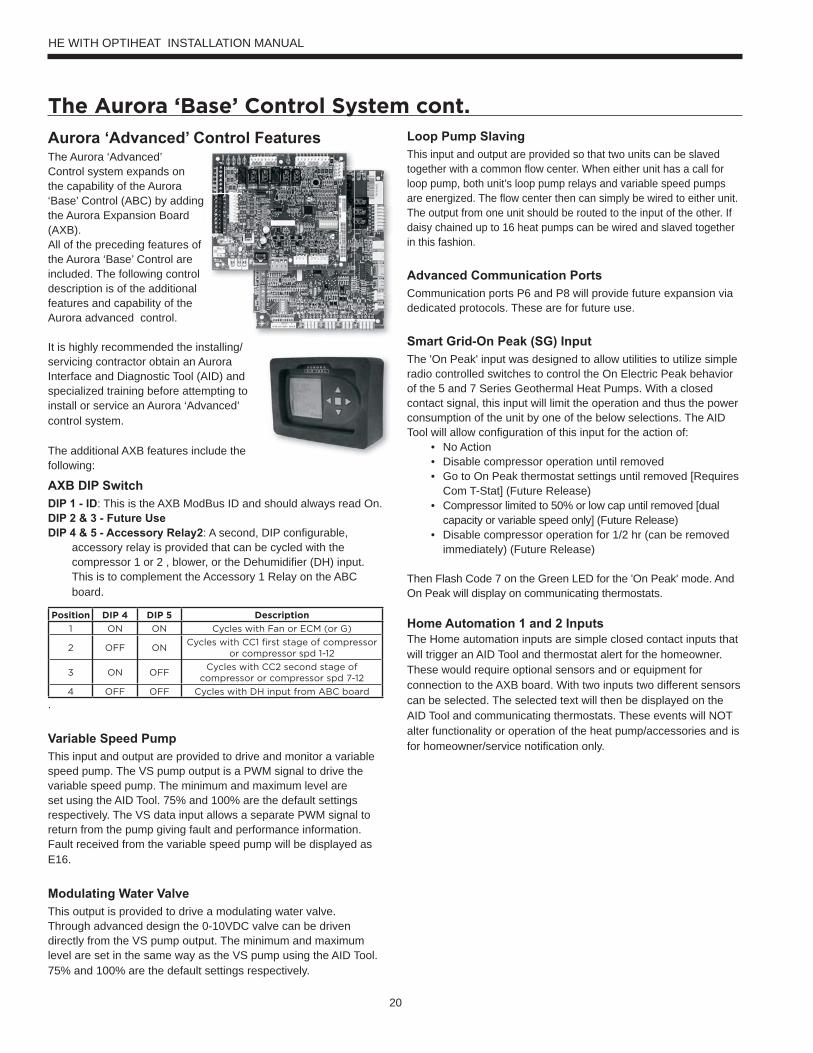
Aurora ‘Advanced’ Control FeaturesThe Aurora ‘Advanced’ Control system expands on the capability of the Aurora ‘Base’ Control (ABC) by adding the Aurora Expansion Board (AXB).All of the preceding features of the Aurora ‘Base’ Control are included. The following control description is of the additional features and capability of the Aurora advanced control.
It is highly recommended the installing/servicing contractor obtain an Aurora Interface and Diagnostic Tool (AID) and specialized training before attempting to install or service an Aurora ‘Advanced’ control system.
The additional AXB features include the following:
AXB DIP Switch DIP 1 - ID: This is the AXB ModBus ID and should always read On.DIP 2 & 3 - Future UseDIP 4 & 5 - Accessory Relay2: A second, DIP configurable,
accessory relay is provided that can be cycled with the compressor 1 or 2 , blower, or the Dehumidifier (DH) input. This is to complement the Accessory 1 Relay on the ABC board.
Position DIP 4 DIP 5 Description
1 ON ON Cycles with Fan or ECM (or G)
2 OFF ONCycles with CC1 first stage of compressor
or compressor spd 1-12
3 ON OFFCycles with CC2 second stage of
compressor or compressor spd 7-12
4 OFF OFF Cycles with DH input from ABC board
.
Variable Speed PumpThis input and output are provided to drive and monitor a variable speed pump. The VS pump output is a PWM signal to drive the variable speed pump. The minimum and maximum level are set using the AID Tool. 75% and 100% are the default settings respectively. The VS data input allows a separate PWM signal to return from the pump giving fault and performance information. Fault received from the variable speed pump will be displayed as E16.
Modulating Water ValveThis output is provided to drive a modulating water valve. Through advanced design the 0-10VDC valve can be driven directly from the VS pump output. The minimum and maximum level are set in the same way as the VS pump using the AID Tool. 75% and 100% are the default settings respectively.
Loop Pump SlavingThis input and output are provided so that two units can be slaved together with a common flow center. When either unit has a call for loop pump, both unit’s loop pump relays and variable speed pumps are energized. The flow center then can simply be wired to either unit. The output from one unit should be routed to the input of the other. If daisy chained up to 16 heat pumps can be wired and slaved together in this fashion.
Advanced Communication PortsCommunication ports P6 and P8 will provide future expansion via dedicated protocols. These are for future use.
Smart Grid-On Peak (SG) InputThe 'On Peak' input was designed to allow utilities to utilize simple radio controlled switches to control the On Electric Peak behavior of the 5 and 7 Series Geothermal Heat Pumps. With a closed contact signal, this input will limit the operation and thus the power consumption of the unit by one of the below selections. The AID Tool will allow configuration of this input for the action of:
• No Action• Disable compressor operation until removed• Go to On Peak thermostat settings until removed [Requires
Com T-Stat] (Future Release)• Compressor limited to 50% or low cap until removed [dual
capacity or variable speed only] (Future Release)• Disable compressor operation for 1/2 hr (can be removed
immediately) (Future Release)
Then Flash Code 7 on the Green LED for the 'On Peak' mode. And On Peak will display on communicating thermostats.
Home Automation 1 and 2 Inputs The Home automation inputs are simple closed contact inputs that will trigger an AID Tool and thermostat alert for the homeowner. These would require optional sensors and or equipment for connection to the AXB board. With two inputs two different sensors can be selected. The selected text will then be displayed on the AID Tool and communicating thermostats. These events will NOT alter functionality or operation of the heat pump/accessories and is for homeowner/service notification only.
The Aurora ‘Base’ Control System cont.
HE WITH OPTIHEAT INSTALLATION MANUAL
21
Home Automation 1 - E23 HA1With a closed dry contact signal, this input will cause an alarm and Alert Code 23 to indicate on the stat or flash on ABC. The AID Tool will allow configuration of this input between the following selections:
• No Action• Home Automation Fault [no lockout info only]
- Output from home automation system• Security Alarm [no lockout info only]
- Output from home security• Sump Alarm Fault [no lockout info only]
- Switch output from sump sensor• Smoke/CO Alarm Fault [no lockout info only]
- Switch output from Smoke/CO sensor• Dirty Filter Alarm [no lockout info only]
- Output from dirty filter sensor
Home Automation 2 – E24 HA2With a closed dry contact signal, this input will cause an alarm and Alert Code 24 to indicate on the stat or flash on ABC. The AID Tool will allow configuration of this input between the following selections:
• No Action• Home Automation Fault [no lockout info only]
- Output from home automation system• Security Alarm [no lockout info only]
- Output from home security• Sump Alarm Fault [no lockout info only]
- Switch output from sump sensor• Smoke/CO Alarm Fault [no lockout info only]
- Switch output from Smoke/CO sensor• Dirty Filter Alarm [no lockout info only]
- Output from dirty filter sensor
Aurora ‘Advanced’ Control LED DisplaysThese three LEDs display the status, configuration, and fault codes for the control. These can also be read in plain English via the Aurora AID Tool.
Status LED (LED3, Green)
Description of Operation Fault LED, GreenNormal Mode ONControl is Non-functional OFFTest Mode Slow FlashLockout Active Fast FlashDehumidification Mode Flash Code 2Load Shed Flash Code 5Emergency Shutdown Flash Code 6On Peak Mode Flash Code 7(Future Use) Flash Code 8(Future Use) Flach Code 9
Fault LED (LED1, Red)Red Fault LED LED Flash
Code * Lockout Reset/ Remove Fault Condition Summary
AB
C B
asic
Fau
lts
Normal - No Faults Off -Fault-Input 1 No Auto Tstat input error. Autoreset upon condition removal.Fault-High Pressure 2 Yes Hard or Soft HP switch has tripped (>600 psi)Fault-Low Pressure 3 Yes Hard or Soft Low Pressure Switch has tripped (<40 psi for 30 continuous sec.)Fault-Freeze Detection FP2 4 Yes Hard or Soft Freeze protection sensor has tripped (<15 or 30 degF for 30 continuous sec.)Fault-Freeze Detection FP1 5 Yes Hard or Soft Freeze protection sensor has tripped (<15 or 30 degF for 30 continuous sec.)Fault-Condensate Overflow 7 Yes Hard or Soft Condensate switch has shown continuity for 30 continuous sec.Fault-Over/Under Voltage 8 No Auto Instantaneous voltage is out of range. **Controls shut down until resolved.Fault-FP1 & 2 Snsr Error 11 Yes Hard or Soft If FP1 or 2 Sensor Error
AB
C &
AXB
Adv
ance
d Fa
ults
Fault-Compressor Monitor 10 Yes Hard or Soft Open Crkt, Run, Start or welded contNon-CriticAXBSnsrErr 13 No Auto Any Other Sensor ErrorCriticAXBSnsrErr 14 Yes Hard or Soft Sensor Error for EEV or HWAlert-HotWtr 15 No Auto HW over limit or logic lockout. HW pump deactivated.Fault-VarSpdPump 16 No Auto Alert is read from PWM feedback.Not Used 17 No Auto IZ2 Com Fault. Autoreset upon condition removal.Non-CritComErr 18 No Auto Any non-critical com errorFault-CritComErr 19 No Auto Any critical com error. Auto reset upon condition removalAlarm - Low Loop Pressure 21 No Auto Loop pressure is below 3 psi for more than 3 minutesAlarm - Home Automation 1 23 No Auto Closed contact input is present on Dig 2 input - Text is configurableAlarm - Home Automation 2 24 No Auto Closed contact input is present on Dig 3 input - Text is configurable
NOTES: *All codes >11 use long flash for tens digit and short flash for the ones digit. 20, 30, 40, 50 etc. are skipped!Alert’ is a noncritical sensor or function that has failed. Normal operation of the heat pump is maintained but service is desired at some point.
The Aurora ‘Base’ Control System cont.
HE WITH OPTIHEAT INSTALLATION MANUAL
22
Reference Calculations
Legend and Notes
Heating Calculations: LWT = EWT - HE
GPM x C*
Cooling Calculations: LWT = EWT + HR
GPM x C*
HE = C* x GPM x (EWT - LWT) HR = C* x GPM x (LWT - EWT)
NOTE: * C = 500 for pure water, 485 for brine.
Abbreviations and DefinitionsELT = entering load fluid temperature to heat pump kW = kilowatts
SWPD = source coax water pressure drop EST = entering source fluid temperature to heat pump
LLT = leaving load fluid temperature from heat pump HE = heat extracted in MBTUH
PSI = pressure drop in pounds per square inch LST = leaving source fluid temperature from heat pump
LGPM = load flow in gallons per minute HC = total heating capacity in MBTUH
FT HD = pressure drop in feet of head COP = coefficient of performance, heating [HC/kW x 3.413]
LWPD = load coax water pressure drop EER = energy efficiency ratio, cooling
LWT = leaving water temperature TC = total cooling capacity in MBTUH
EWT = entering water temperature HR = heat rejected in MBTUH
Brine = water with a freeze inhibiting solution
Notes to Performance Data TablesThe following notes apply to all performance data tables:• Three flow rates are shown for each unit. The lowest flow rate shown is used for geothermal open loop/well water systems with a minimum of 50°F EST. The middle flow rate shown is the minimum geothermal closed loop flow rate. The highest flow rate shown is optimum for geothermal closed loop systems and the suggested flow rate for boiler/ tower applications. • Entering water temperatures below 40°F assumes 15% antifreeze solution. • Interpolation between ELT, EST, and GPM data is permissible. • Operation in the gray areas is not recommended.
HE WITH OPTIHEAT INSTALLATION MANUAL
23
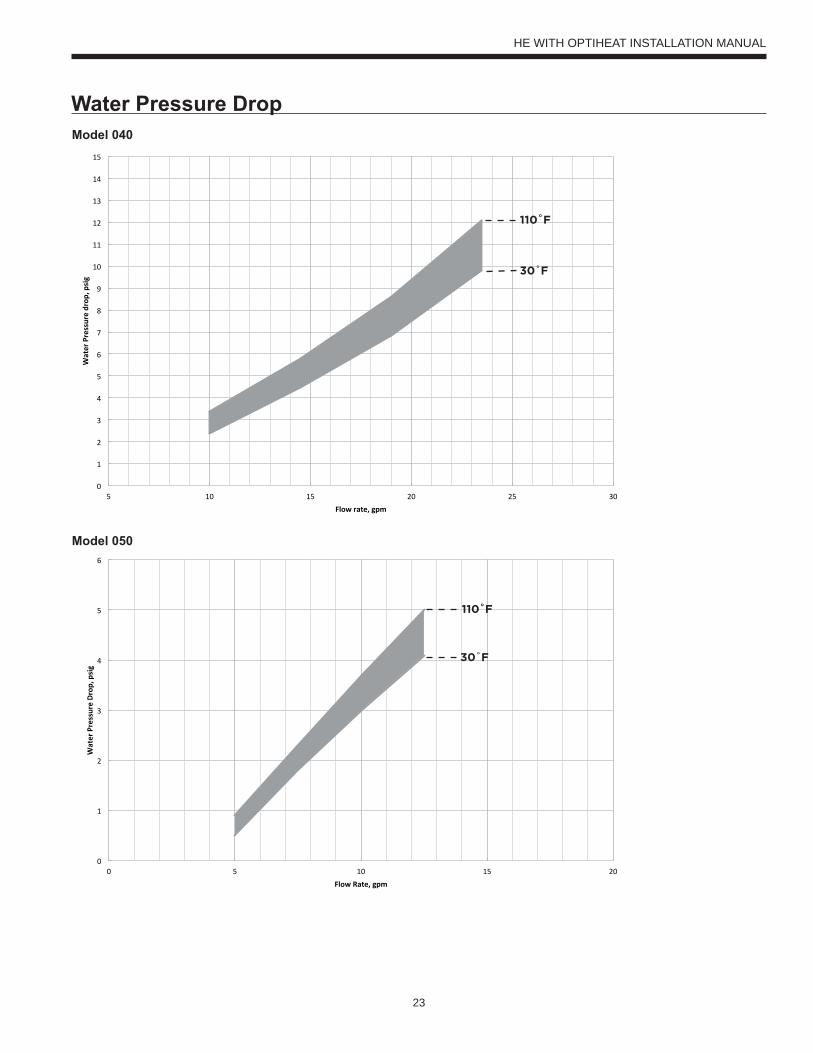
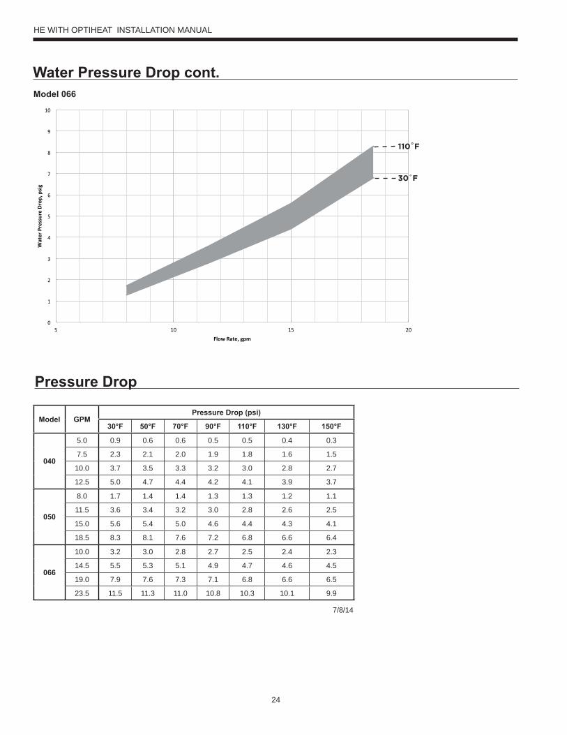
Water Pressure Drop
110˚F
30˚F
110˚F
30˚F
Model 040
Model 050
HE WITH OPTIHEAT INSTALLATION MANUAL
24
Water Pressure Drop cont.
110˚F
30˚F
Pressure Drop
Model 066
Model GPMPressure Drop (psi)
30°F 50°F 70°F 90°F 110°F 130°F 150°F
040
5.0 0.9 0.6 0.6 0.5 0.5 0.4 0.3
7.5 2.3 2.1 2.0 1.9 1.8 1.6 1.5
10.0 3.7 3.5 3.3 3.2 3.0 2.8 2.7
12.5 5.0 4.7 4.4 4.2 4.1 3.9 3.7
050
8.0 1.7 1.4 1.4 1.3 1.3 1.2 1.1
11.5 3.6 3.4 3.2 3.0 2.8 2.6 2.5
15.0 5.6 5.4 5.0 4.6 4.4 4.3 4.1
18.5 8.3 8.1 7.6 7.2 6.8 6.6 6.4
066
10.0 3.2 3.0 2.8 2.7 2.5 2.4 2.3
14.5 5.5 5.3 5.1 4.9 4.7 4.6 4.5
19.0 7.9 7.6 7.3 7.1 6.8 6.6 6.5
23.5 11.5 11.3 11.0 10.8 10.3 10.1 9.9
7/8/14
HE WITH OPTIHEAT INSTALLATION MANUAL
25
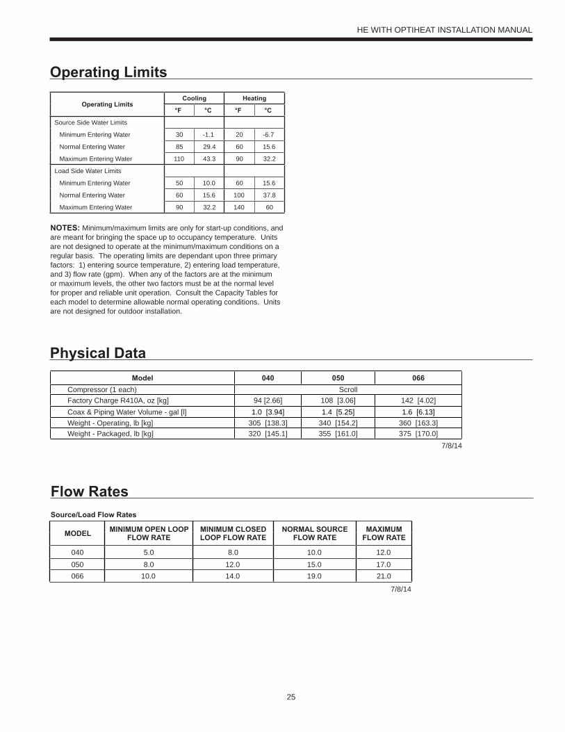
Operating Limits
Operating LimitsCooling Heating
°F °C °F °C
Source Side Water Limits
Minimum Entering Water 30 -1.1 20 -6.7
Normal Entering Water 85 29.4 60 15.6
Maximum Entering Water 110 43.3 90 32.2
Load Side Water Limits
Minimum Entering Water 50 10.0 60 15.6
Normal Entering Water 60 15.6 100 37.8
Maximum Entering Water 90 32.2 140 60
NOTES: Minimum/maximum limits are only for start-up conditions, and are meant for bringing the space up to occupancy temperature. Units are not designed to operate at the minimum/maximum conditions on a regular basis. The operating limits are dependant upon three primary factors: 1) entering source temperature, 2) entering load temperature, and 3) flow rate (gpm). When any of the factors are at the minimum or maximum levels, the other two factors must be at the normal level for proper and reliable unit operation. Consult the Capacity Tables for each model to determine allowable normal operating conditions. Units are not designed for outdoor installation.
Flow Rates
Model 040 050 066Compressor (1 each) ScrollFactory Charge R410A, oz [kg] 94 [2.66] 108 [3.06] 142 [4.02]Coax & Piping Water Volume - gal [l] 1.0 [3.94] 1.4 [5.25] 1.6 [6.13]Weight - Operating, lb [kg] 305 [138.3] 340 [154.2] 360 [163.3]Weight - Packaged, lb [kg] 320 [145.1] 355 [161.0] 375 [170.0]
7/8/14
Physical Data
Source/Load Flow Rates
MODEL MINIMUM OPEN LOOP FLOW RATE
MINIMUM CLOSED LOOP FLOW RATE
NORMAL SOURCE FLOW RATE
MAXIMUM FLOW RATE
040 5.0 8.0 10.0 12.0050 8.0 12.0 15.0 17.0066 10.0 14.0 19.0 21.0
7/8/14
HE WITH OPTIHEAT INSTALLATION MANUAL
26
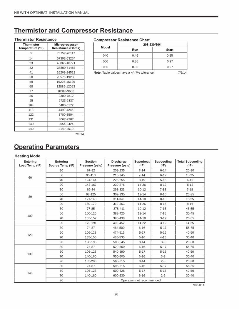
Thermistor and Compressor ResistanceThermistor Resistance
ThermistorTemperature (°F)
MicroprocessorResistance (Ohms)
5 75757-70117
14 57392-5323423 43865-4077132 33809-3148741 26269-2451350 20570-1923059 16226-1519668 12889-1209377 10310-968886 8300-781295 6723-6337
104 5480-5172113 4490-4246122 3700-3504131 3067-2907140 2554-2424149 2149-2019
7/8/14
Compressor Resistance Chart
Model208-230/60/1
Run Start
040 0.46 0.85
050 0.36 0.97
066 0.36 0.97
Note: Table values have a +/- 7% tolerance 7/8/14
Operating ParametersHeating Mode
EnteringLoad Temp (oF)
EnteringSource Temp (oF)
SuctionPressure (psig)
Discharge Pressure (psig)
Superheat (oF)
Subcooling(oF)
Total Subcooling(oF)
60
30 67-82 208-235 7-14 6-14 20-3050 95-113 216-245 7-14 6-12 15-2570 124-144 225-255 8-19 5-15 6-1690 143-167 230-275 14-26 8-12 8-12
80
30 69-84 293-323 10-12 7-18 7-1850 98-125 302-335 12-14 8-16 25-3570 121-148 311-346 14-18 8-16 15-2590 150-179 319-363 14-26 8-16 8-16
100
30 77-85 378-411 10-12 7-15 45-5550 100-126 388-425 12-14 7-15 30-4570 133-152 398-438 14-18 3-12 25-3590 170-191 408-452 14-22 3-12 14-25
120
30 74-87 464-500 6-16 5-17 55-6550 106-128 474-515 5-17 5-15 40-5070 135-156 485-530 6-16 4-15 30-4090 180-195 500-545 8-14 3-9 20-30
130
30 74-87 520-560 6-16 5-17 55-6550 106-128 540-590 5-17 5-15 40-5070 140-160 550-600 6-16 3-9 30-4090 185-200 560-615 8-14 2-8 20-30
140
30 74-87 595-615 6-16 5-17 55-6550 106-128 600-625 5-17 5-15 40-5070 140-160 600-630 6-16 2-6 30-4090 Operation not recommended
7/8/2014
HE WITH OPTIHEAT INSTALLATION MANUAL
27
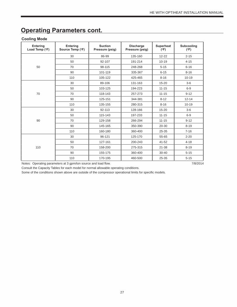
Operating Parameters cont.Cooling Mode
EnteringLoad Temp (oF)
EnteringSource Temp (oF)
SuctionPressure (psig)
Discharge Pressure (psig)
Superheat (oF)
Subcooling(oF)
50
30 86-99 135-160 12-22 2-15
50 92-107 191-214 10-19 4-15
70 98-115 248-268 5-15 6-16
90 101-119 335-367 6-15 8-16
110 105-122 425-465 8-16 10-19
70
30 89-106 131-163 15-20 3-6
50 103-125 194-223 11-15 6-9
70 118-143 257-273 11-15 9-12
90 125-151 344-381 8-12 12-14
110 135-155 280-315 8-16 10-19
90
30 92-113 128-166 15-20 3-6
50 115-143 197-233 11-15 6-9
70 129-158 266-294 11-15 9-12
90 145-165 350-390 20-30 8-19
110 160-180 360-400 25-35 7-16
110
30 96-121 125-170 55-65 2-20
50 127-161 200-243 41-52 4-18
70 158-200 275-315 21-38 8-19
90 155-175 360-400 30-40 5-15
110 170-195 460-500 25-35 5-15
Notes: Operating parameters at 3 gpm/ton source and load flow. 7/8/2014 Consult the Capacity Tables for each model for normal allowable operating conditions. Some of the conditions shown above are outside of the compressor operational limits for specific models.
HE WITH OPTIHEAT INSTALLATION MANUAL
28
Antifreeze Correction
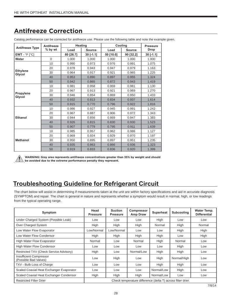
Troubleshooting Guideline for Refrigerant CircuitThe chart below will assist in determining if measurements taken at the unit are within factory specifications and aid in accurate diagnosis (SYMPTOM) and repair. The chart is general in nature and represents whether a symptom would result in normal, high, or low readings from the typical operating range.
Symptom Head Pressure
Suction Pressure
CompressorAmp Draw Superheat Subcooling Water Temp.
DifferentialUnder Charged System (Possible Leak) Low Low Low High Low Low
Over Charged System High High High Normal High Normal
Low Water Flow Evaporator Low/Normal Low/Normal Low Low High High
Low Water Flow Condensor High High High High Low High
High Water Flow Evaporator Normal Low Normal High Normal Low
High Water Flow Condensor Low Low Low Low High Low
Restricted TXV (Check Service Advisory) High Low Normal/Low High High LowInsufficient Compressor (Possible Bad Valves) Low High Low High Normal/High Low
TXV - Bulb Loss of Charge Low Low Low High High Low
Scaled Coaxial Heat Exchanger Evaporator Low Low Low Normal/Low High Low
Scaled Coaxial Heat Exchanger Condensor High High High Normal/Low Low Low
Restricted Filter Drier Check temperature difference (delta T) across filter drier.7/8/14
Catalog performance can be corrected for antifreeze use. Please use the following table and note the example given.
Antifreeze Type Antifreeze % by wt
Heating Cooling Pressure DropLoad Source Load Source
EWT - °F [°C] 80 [26.7] 30 [-1.1] 50 [10.0] 90 [32.2] 30 [-1.1]Water 0 1.000 1.000 1.000 1.000 1.000
Ethylene Glycol
10 0.990 0.973 0.976 0.991 1.07520 0.978 0.943 0.947 0.979 1.16330 0.964 0.917 0.921 0.965 1.22540 0.953 0.890 0.897 0.955 1.32450 0.942 0.865 0.872 0.943 1.419
Propylene Glycol
10 0.981 0.958 0.959 0.981 1.13020 0.967 0.913 0.921 0.969 1.27030 0.946 0.854 0.869 0.950 1.43340 0.932 0.813 0.834 0.937 1.61450 0.915 0.770 0.796 0.922 1.816
Ethanol
10 0.986 0.927 0.945 0.991 1.24220 0.967 0.887 0.906 0.972 1.34330 0.944 0.856 0.869 0.947 1.38340 0.926 0.815 0.830 0.930 1.52350 0.907 0.779 0.795 0.911 1.639
Methanol
10 0.985 0.957 0.962 0.986 1.12720 0.969 0.924 0.929 0.970 1.19730 0.950 0.895 0.897 0.951 1.23540 0.935 0.863 0.866 0.936 1.32350 0.919 0.833 0.836 0.920 1.399
WARNING: Gray area represents antifreeze concentrations greater than 35% by weight and should be avoided due to the extreme performance penalty they represent.
HE WITH OPTIHEAT INSTALLATION MANUAL
29
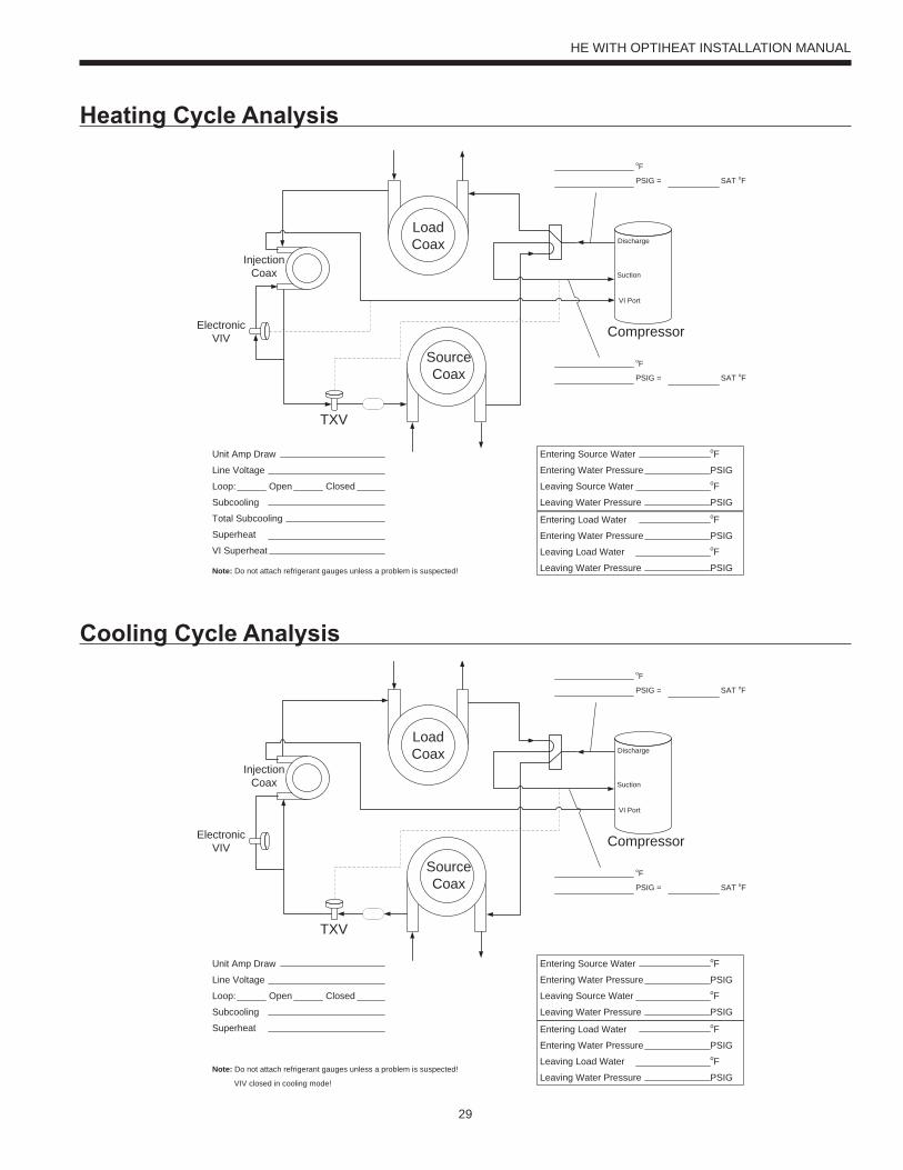
Heating Cycle Analysis
Cooling Cycle Analysis
Unit Amp Draw
Line Voltage
Loop: Open Closed
Subcooling
Total Subcooling
Superheat
VI Superheat
Entering Source Water oF
Entering Water Pressure PSIG
Leaving Source Water oF
Leaving Water Pressure PSIG
Entering Load Water oF
Entering Water Pressure PSIG
Leaving Load Water oF
Leaving Water Pressure PSIGNote: Do not attach refrigerant gauges unless a problem is suspected!
TXV
ElectronicVIV
LoadCoax
InjectionCoax
SourceCoax
Suction
Discharge
VI Port
Compressor
oF
PSIG = SAT oF
oF
PSIG = SAT oF
TXV
ElectronicVIV
LoadCoax
InjectionCoax
SourceCoax
Suction
Discharge
VI Port
Compressor
oF
PSIG = SAT oF
oF
PSIG = SAT oF
Entering Source Water oF
Entering Water Pressure PSIG
Leaving Source Water oF
Leaving Water Pressure PSIG
Entering Load Water oF
Entering Water Pressure PSIG
Leaving Load Water oF
Leaving Water Pressure PSIGNote: Do not attach refrigerant gauges unless a problem is suspected!
VIV closed in cooling mode!
Unit Amp Draw
Line Voltage
Loop: Open Closed
Subcooling
Superheat
HE WITH OPTIHEAT INSTALLATION MANUAL
30
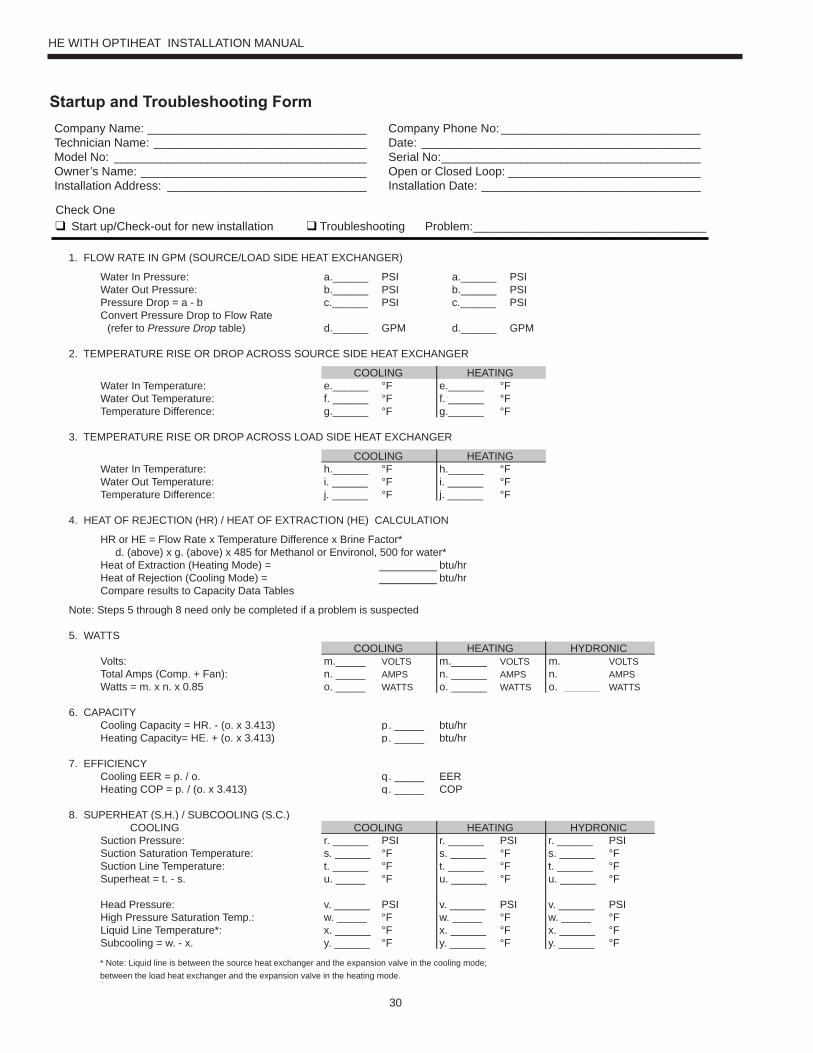
Check One Start up/Check-out for new installation Troubleshooting Problem:___________________________________
1. FLOW RATE IN GPM (SOURCE/LOAD SIDE HEAT EXCHANGER)
Water In Pressure: a.______ PSIWater Out Pressure: b.______ PSIPressure Drop = a - b c.______ PSIConvert Pressure Drop to Flow Rate (refer to Pressure Drop table) d.______ GPM
a.______ PSIb.______ PSIc.______ PSI d.______ GPM
2. TEMPERATURE RISE OR DROP ACROSS SOURCE SIDE HEAT EXCHANGER
COOLING HEATINGWater In Temperature: e.______ °F e.______ °FWater Out Temperature: f. ______ °F f. ______ °FTemperature Difference: g.______ °F g.______ °F
3. TEMPERATURE RISE OR DROP ACROSS LOAD SIDE HEAT EXCHANGER
COOLING HEATINGWater In Temperature: h.______ °F h.______ °FWater Out Temperature: i. ______ °F i. ______ °FTemperature Difference: j. ______ °F j. ______ °F
4. HEAT OF REJECTION (HR) / HEAT OF EXTRACTION (HE) CALCULATION
HR or HE = Flow Rate x Temperature Difference x Brine Factor* d. (above) x g. (above) x 485 for Methanol or Environol, 500 for water*Heat of Extraction (Heating Mode) = btu/hrHeat of Rejection (Cooling Mode) = btu/hrCompare results to Capacity Data Tables
Note: Steps 5 through 8 need only be completed if a problem is suspected
5. WATTSCOOLING HEATING HYDRONIC
Volts: m._____ VOLTS m.______ VOLTS m. ______ VOLTSTotal Amps (Comp. + Fan): n. _____ AMPS n. ______ AMPS n. ______ AMPSWatts = m. x n. x 0.85 o. _____ WATTS o. ______ WATTS o. ______ WATTS
6. CAPACITYCooling Capacity = HR. - (o. x 3.413) p. _____ btu/hrHeating Capacity= HE. + (o. x 3.413) p. _____ btu/hr
7. EFFICIENCYCooling EER = p. / o. q. _____ EERHeating COP = p. / (o. x 3.413) q. _____ COP
8. SUPERHEAT (S.H.) / SUBCOOLING (S.C.) COOLING HEATING HYDRONICSuction Pressure: r. ______ PSI r. ______ PSI r. ______ PSISuction Saturation Temperature: s. ______ °F s. ______ °F s. ______ °FSuction Line Temperature: t. ______ °F t. ______ °F t. ______ °FSuperheat = t. - s. u. _____ °F u. ______ °F u. ______ °F
Head Pressure: v. ______ PSI v. ______ PSI v. ______ PSIHigh Pressure Saturation Temp.: w. _____ °F w. _____ °F w. _____ °FLiquid Line Temperature*: x. ______ °F x. ______ °F x. ______ °FSubcooling = w. - x. y. ______ °F y. ______ °F y. ______ °F
* Note: Liquid line is between the source heat exchanger and the expansion valve in the cooling mode; between the load heat exchanger and the expansion valve in the heating mode.
Company Name: _________________________________Technician Name: ________________________________Model No: ______________________________________Owner’s Name: __________________________________Installation Address: ______________________________
Company Phone No: ______________________________Date: __________________________________________Serial No:_______________________________________Open or Closed Loop: _____________________________Installation Date: _________________________________
COOLING
Startup and Troubleshooting Form
HE WITH OPTIHEAT INSTALLATION MANUAL
31
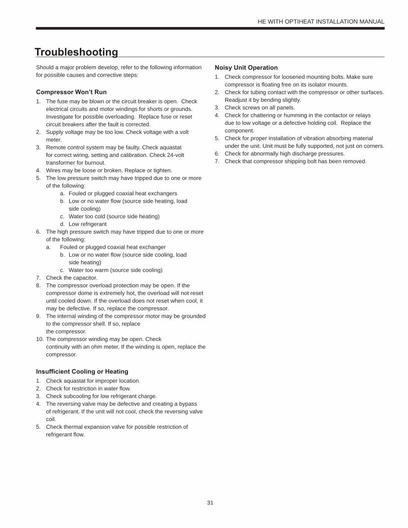
TroubleshootingShould a major problem develop, refer to the following information for possible causes and corrective steps:
Compressor Won’t Run1. The fuse may be blown or the circuit breaker is open. Check
electrical circuits and motor windings for shorts or grounds. Investigate for possible overloading. Replace fuse or reset circuit breakers after the fault is corrected.
2. Supply voltage may be too low. Check voltage with a volt meter.
3. Remote control system may be faulty. Check aquastat for correct wiring, setting and calibration. Check 24-volt transformer for burnout.
4. Wires may be loose or broken. Replace or tighten.5. The low pressure switch may have tripped due to one or more
of the following: a. Fouled or plugged coaxial heat exchangers
b. Low or no water flow (source side heating, load side cooling) c. Water too cold (source side heating) d. Low refrigerant6. The high pressure switch may have tripped due to one or more
of the following: a. Fouled or plugged coaxial heat exchanger
b. Low or no water flow (source side cooling, load side heating) c. Water too warm (source side cooling)7. Check the capacitor.8. The compressor overload protection may be open. If the
compressor dome is extremely hot, the overload will not reset until cooled down. If the overload does not reset when cool, it may be defective. If so, replace the compressor.
9. The internal winding of the compressor motor may be grounded to the compressor shell. If so, replacethe compressor.
10. The compressor winding may be open. Checkcontinuity with an ohm meter. If the winding is open, replace the compressor.
Insufficient Cooling or Heating1. Check aquastat for improper location.2. Check for restriction in water flow.3. Check subcooling for low refrigerant charge.4. The reversing valve may be defective and creating a bypass
of refrigerant. If the unit will not cool, check the reversing valve coil.
5. Check thermal expansion valve for possible restriction of refrigerant flow.
Noisy Unit Operation1. Check compressor for loosened mounting bolts. Make sure
compressor is floating free on its isolator mounts.2. Check for tubing contact with the compressor or other surfaces.
Readjust it by bending slightly.3. Check screws on all panels.4. Check for chattering or humming in the contactor or relays
due to low voltage or a defective holding coil. Replace the component.
5. Check for proper installation of vibration absorbing material under the unit. Unit must be fully supported, not just on corners.
6. Check for abnormally high discharge pressures.7. Check that compressor shipping bolt has been removed.
HE WITH OPTIHEAT INSTALLATION MANUAL
32
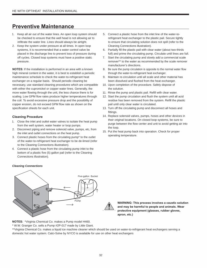
Preventive Maintenance1. Keep all air out of the water lines. An open loop system should
be checked to ensure that the well head is not allowing air to infiltrate the water line. Lines should always be airtight.
2. Keep the system under pressure at all times. In open loop systems, it is recommended that a water control valve be placed in the discharge line to prevent loss of pressure during off cycles. Closed loop systems must have a positive static pressure.
NOTES: If the installation is performed in an area with a known high mineral content in the water, it is best to establish a periodic maintenance schedule to check the water-to-refrigerant heat exchanger on a regular basis. Should periodic cleaning be necessary, use standard cleaning procedures which are compatible with either the cupronickel or copper water lines. Generally, the more water flowing through the unit, the less chance there is for scaling. Low GPM flow rates produce higher temperatures through the coil. To avoid excessive pressure drop and the possibility of copper erosion, do not exceed GPM flow rate as shown on the specification sheets for each unit.
Cleaning Procedure1. Close the inlet and outlet water valves to isolate the heat pump
from the well system, water heater or loop pumps.2. Disconnect piping and remove solenoid valve, pumps, etc, from
the inlet and outlet connections on the heat pump.3. Connect plastic hoses from the circulating pump* to the outlet
of the water-to-refrigerant heat exchanger to be de-limed (refer to the Cleaning Connections illustration).
4. Connect a plastic hose from the circulating pump inlet to the bottom of a plastic five (5) gallon pail (refer to the Cleaning Connections illustration).
5. Connect a plastic hose from the inlet line of the water-to-refrigerant heat exchanger to the plastic pail. Secure tightly to ensure that circulating solution does not spill (refer to the Cleaning Connections illustration).
6. Partially fill the plastic pail with clear water (about two-thirds full) and prime the circulating pump. Circulate until lines are full.
7. Start the circulating pump and slowly add a commercial scale remover** to the water as recommended by the scale remover manufacturer’s directions.
8. Be sure the pump circulation is opposite to the normal water flow through the water-to-refrigerant heat exchanger.
9. Maintain re-circulation until all scale and other material has been dissolved and flushed from the heat exchanger.
10. Upon completion of the procedure. Safely dispose ofthe solution.
11. Rinse the pump and plastic pail. Refill with clear water.12. Start the pump circulation and flush the system until all acid
residue has been removed from the system. Refill the plastic pail until only clear water is circulated.
13. Turn off the circulating pump and disconnect all hoses and fittings.
14. Replace solenoid valves, pumps, hoses and other devices in their original locations. On closed loop systems, be sure to purge between the flow center and unit to avoid getting air into the loop.
15. Put the heat pump back into operation. Check for proper operating temperature.
NOTES: *Virginia Chemical Co. makes a Pump model H460.* W.W. Granger Co. sells a Pump #2P-017 made by Little Giant.**Virginia Chemical Co. makes a liquid ice machine cleaner which should be used on water-to-refrigerant heat exchangers serving a domestic hot water system. Calci-Solve by NYCO is available for use on other heat exchangers
Cleaning Connections
WARNING: This process involves a caustic solution and may be harmful to people and animals. Wear protective equipment (glasses, rubber gloves, apron, etc.)
Five-gallon Bucket
Pump
HE WITH OPTIHEAT INSTALLATION MANUAL
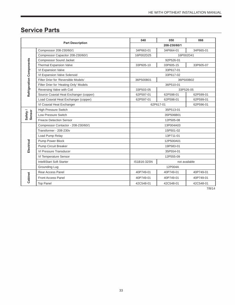
33
Service Parts
Part Description040 050 066
208-230/60/1
Ref
riger
atio
n C
ompo
nent
s
Compressor 208-230/60/1 34P663-01 34P664-01 34P665-01Compressor Capacitor 208-230/60/1 16P002D25 16P002D41Compressor Sound Jacket 92P526-01Thermal Expansion Valve 33P605-10 33P605-15 33P605-07VI Expansion Valve 33P617-01VI Expansion Valve Solenoid 33P617-02Filter Drier for ‘Reversible Models’ 36P500B01 36P500B02Filter Drier for ‘Heating Only’ Models 36P510-01Reversing Valve with Coil 33P503-05 33P526-05Source Coaxial Heat Exchanger (copper) 62P597-01 62P598-01 62P599-01Load Coaxial Heat Exchanger (copper) 62P597-01 62P598-01 62P599-01VI Coaxial Heat Exchanger 62P617-01 62P596-01
Safe
ty /
Sens
or High Pressure Switch 35P513-01
Low Pressure Switch 35P506B01
Freeze Detection Sensor 12P505-08
Elec
tric
al
Compressor Contactor - 208-230/60/1 13P004A03
Transformer - 208-230v 15P501-02
Load Pump Relay 13P711-01
Pump Power Block 12P500A01
Pump Circuit Breaker 19P583-01
VI Pressure Transducer 35P554-01
VI Temperature Sensor 12P555-09
IntelliStart Soft Starter IS1B16-32SN not available
Grounding Lug 12P004A
Cab
inet Rear Access Panel 40P749-01 40P749-01 40P749-01
Front Access Panel 40P749-01 40P749-01 40P749-01
Top Panel 42C548-01 42C548-01 42C548-017/8/14
HE WITH OPTIHEAT INSTALLATION MANUAL

34
Notes
HE WITH OPTIHEAT INSTALLATION MANUAL

35
Revision GuidePages: Description: Date: By:
All Literature Creation 5 Feb 2015 MA
HE WITH OPTIHEAT INSTALLATION MANUAL


Product: Premium H Series - HEType: Hydronic Heat Pump with OptiHeat
Size: 3-5 Ton
Document Type: Installation, Operation & Maintenance ManualRef. Number: IM2508WG2Revision Date: 05/15Revision Number: 2Document Name: TEC-IOM-HS_0215v2
290 Pinebush Road, Cambridge, Ontario N1T 1Z6 | o: 1.866.310.6690 | f: 1.866.533.3889
GEOSMART ENERGY.COM


![+RUL]RQWDO:DWHU6RXUFH+HDW3XPSV R-410A Refrigerant](https://static.fdocuments.us/doc/165x107/6236dd32b2287e10322decc1/rulrqwdodwhu6rxufhhdw3xpsv-r-410a-refrigerant.jpg)


