![&XUULFXOXP YLWDH 3URI 'U ,QJ $OYDUR *XWLpUUH]](https://static.fdocuments.us/doc/165x107/58a2f8e11a28ab2d678ba55a/xuulfxoxp-ylwdh-3uri-u-qj-oydur-xwlpuuh.jpg)
*R .-* 3* :’-!J~~+ !qj~ ‘-lG,.&. v
37
1: !’ 6.. -. --.’-. ::- W:-I; L-L *,., P .. ! ., ...:,, , ,. . . . . . . *R .-* ‘i : ,.. 3* :’-!J~~+ !qj~ ‘-lG,.&. @2!t@t. .. ! ... i ,,- ,. iij} v<, [A?? f TECHiiICAL NOTES ‘NATIONAL ADVISORY COMMITTEE FOR t tic).585 ., -==”- . -U---,m= :.- : :.: ---- =* .. — ., ------ - “w’ IJ3CHAN1CAL PROPERTIES OF ALUMINUM-ALLOY RIVETS By Wm. C. Brueggeman ~~ational Bureau of standards ——.——— Washington November 1936 . -- .- — -, .-” . -. ,---- .. . #
Transcript of *R .-* 3* :’-!J~~+ !qj~ ‘-lG,.&. v

1: !’6..-.--.’-.::-W:-I;L-L *,.,P
. . ! ., ...:,, , ,. . . . . . .
*R .-* ‘i : ,.. 3*
:’-!J~~+ !qj~
‘-lG,.&. @2!t@t. . .! ...i ,,-,. iij} v<,[A??f TECHiiICAL NOTES
‘NATIONAL ADVISORY COMMITTEE FOR
t
tic).585
., -==”-. -U---,m= :.- : :.: ---- =*. . — ., ------
- “w’
IJ3CHAN1 CAL PROPERTIES OF ALUMINUM-ALLOY RIVETS
By Wm. C. Brueggeman~~ational Bureau of standards
——.———
Washington
November 1936
.
--
.-
—-,
.-”
.
-.
,----. . .
#

,- -
. ...
—.
NAT IOIJAL ADVISORY COMMITTEE FOR AERONAUTICS ‘--—
——— -.-—
Tl!CHNICAL NOTE NO. 585—
MECHANICAL PROPERTIES Or ALUMINUM-ALLOY RIVETS
By Wm. C. Brueggeman
I. INTRODUCTION
The development of metal construction for aircraft hascreated a need for accurate and detailed information re-garding the strength of riveted joints in aluminum-alloystructures. To o%tain this information the National Bureauof Standards in cooperation with the National Advisory Com-mittee for Aeronautics is investigating the strength ofriveted joints in aluminum alloys.
The strength of riveted joints may be influenced bythe form of the head, the ratio of the rivet diameter tothe sheet thickness, the driving stress, and other factors.This note gives the-r’esults of ~e~tsing technique for test specimens andfects of these factors.
II. MATERIAL
to develop the rivet-to “determine the ef-
Both rivets and sheet were of alloy 17ST. The mechan-ical properties of the rivets conformed to Navy DepartmentSpecification 43R5”0 for Rivets and Rivet Wire and Rod,Aluminum and Aluminum Alloy (Aircraft Use) Grade C. Themechanical properties of the sheet conformed to Navy Depart-ment Specification 47A3b, Aluminum Alloy (Aluminum-copper-magaesium-manganese) , sheet and plate, physical conditiontype 2, hoa”t-treated.
All rivets were 1/4 inch in diameter and were manu-factured from the same coil of rivet wire. Typical me-chanical properties of the wire in the heat-treated condi-tion are given in table I.
The sheets were 16 inches wide, 14 feet long, and ofthe following thicknesses: 0.051 inch, 0.081 inch, 0.102inch, and 0.125 inch. Typical mechanical properties ofthe sheets are given in talle 11.

2 N.A. C.A, Technical Note No. 585
TABLE I. Typical Mechanical Properties of l/4-Inch
Rivet Wire in the Heat-Treated Condition
Specimen
FYield
numb-er strength,
lb./in.a-——-—— ——
1 34,7502 34,7003 34,8004 33,4005 35,0006 34, 500
TABLX II.
Sheetthickness,
in.
0.051 L*
.051 T*
.081 L
.081 T
.102 L
.102 T
,125 L
.l.z5 T
—————.
Yield Elongation instrength, 4 diameters,
1lb./in.* percent
—---- . —.58,?10 28.058,430 31.058,350 28.658,380 28.8 ~58,510 28.058,350 28.0
-.
--
Typical Mechanical Properties ‘of 17ST” Sheets .——
Yieldstrength,
.lb./fn.8
40,80040,200
35,80035, 600
39,70041,700
35,40036,400
42,90044,000
37,40037,000
40,30043,000
35,”40036,600
—————
Tensilestrength,
Ib./irl.a
60, 63059,050
59 ,2’?058,920
60’,26061,080
59,89060,010
61,47062,540
61, 68061,C?1O
60,80059,940
58,32058,430 ,
—. ___ .—.———*3 = longitudinal; T = transverse.
-—Elongation in
2 inches
percent
--
21
2221
2423
2322
2222
2222
2220
--
20
.+..

N.A. C..A. Technical Note No.. .585 3
111. TypES OF ~AD
The following combinations of types of head were usedin making specimens:
~rtven head Manufactured head—-
round with roundmushroom II mushroombutton 11 roundbrazier II braziercone point 1! roundflat !1 round . .
The head proportions are shown in figure 1. The di-mensions giveu conform to ?iavy specification 43R5b for allt~pes except the cone point and the mushroom.*. The conepoint is a type of head recommended by the Aluminum Com-pany of America for driven heads. Among the advantagesclaimed for it are completeness of the head at low drivingstress, adequate tensile strength., ease of maintainingconcentricity with the shank, the fact that one set may beused to drive several sizes of rivet, and satisfactory ap-pearance. At the present time cone-point heads are notsupplied by t’he manufacturer.
The rivet sets were machined to fit the heads,, usingthe dimensions of figure 1, except for flat and cone-po”intheads. The set for flat heads consisted simply of a flathardened-steel bearing surface.. Yor coqe-point heads theset had a cone-shaped bearing surface.
.
.
‘Iv, PREPARATION Or SPECIWNS
1- Rivets
Figure 2 shows a $ig for cutting the rivets to theexac’t length required. for driving. ‘I% is adjustable to
—
any desired grip (total sheet thickness) and head allow--——____ —. —.—. “ —*Using dimensions given in Specification 43R5b for muphroomheads , the arcs forming the Bead contour do not meet in acommon tangent. For this reison, in making” rivet sets, thedimension R = 1.563d was substituted. for the sp”ec’ifieddimension R = 1.634d. ___

4 N.A,.C.A. Technical Note No. 585
ante (length of shank projecting from the sheets b formt-he driven head).
The rivets were heat-treated ty submerging them for15 minutes in a bath of sodium nitrate held at 940 0 F. andthen quenching in cold water. They were driven within onehour after .qtieiching. Specimens were held at room temper-ature and tested two weeks after driving the rivets.
2. Sheets
The.sheets we”re cut to size by either “sawing or shear-ing. To insure unifbr.mity the hole’s were subdrilled, thenreamed. A hole size was chosen that would insure t-hat thelargest rivet meeting the diame~ tolerance wouL.d enterthe hole. %reely. For” this purpose the plus tolerance(OkO04 in.) of the rivet diameter was added to the nominaldiameter (0.250 in.) , and a special reamer equal in diame-ter to the next larger commercial drill size (F, 0.257 in.)was used.
3. Riveting
All riveting was done By the l~squeeze!’ method. Theload was aEplied in a.hydraulic testing machine, as shownin figure 3. The upper rivet set is ’attached to the upperhead of the machine and the lower set rests on the movableplaten. The sheets w&r:e clamped together during rivetingand were kept in a position normal to the rivet axis bYmeans of a flange and frame centered” about the lower rivetset.
When referring to the pressure applied to the rivetwhen forming the head, the term ‘fdriving- stress” is usedfor convenience. “I”t is a nominal stress obtained by di-vidfng the maximum driving load by the nominal cross-sec-tional area of the shank and is, of course, in all caseslarger than the actual stress on the head.
v. DIK13NSIC)NS OF DRIVEN RIVETS
1. Head (Dimensions
Information was desired on the dimensions of incom-plete heads of the several tYpos” and the driving stress atwhich the dirne”nsions of the driven head”approached those
●
.
.

N.A. C.A. Te&nical Note No. 585 5
of the manufactured head. Measurements of the depth andthe diameter of the driven head were made on all of thetypes shown in figure 1. These ~re plotted against driv-ing stress in figures 4 to 9 inclusive, in terms of thenominal depth and diameter of the manufactured head (scaleat bottom of gra~hs) and nominal shank diameter d, (scaleat top).
.
A head allowance H (fig. 4) sufficient to form anapproximately complete ‘head was used. Rivets were driven
-—
at successively increasing driving stresses until thedriven head was practically complete or until severe radialbuckling and separation of the sheets had occurred. Thecone-point head was found to be the only type tihic”ncouldbe driven to its full nominal diameter without excessivebuckling of t-he sheets.
It is difficult tb express quantitatively the amountof such buckling and it is realized tha”t the permissibleamount probably varies for different a~plications. ~ w-ever , it may be said that a marked buckling and apprec~ableseparation of the sheets began to occur for d/t = 2.0 at
about 325,000 lb./in.= for all joints, and at lo~er driv-ing stresses when d~t was 2.5 and above. —
.It was found that the diameter of the driven he@ was
--—
affected very little by the head allowance H, as show~’– -in figure 4 for round-head rivets. The diameters of fla.~heads , figure 9, showed a simila-r agreemsnt when E was1.5d and 1.’75d. Only the curve for H = 1.5d is plotted.
The several ty-pes of driven he~.ds had nearly the samediameter at the sane driving stress. The gr6aiest differ-ence was between the button head (fig. 6) and the flat head(fig. 9) , which had diameters of approx~mately 1.60d and1.82d, respectively, at 250,000 lb./in. driving stress.
Eccentricity of the flat heads occurred frequentlywhen care was not qxercised in aligning the shan’k aorrnalt? the sti.eetsbefore driving. This effect was not pro-nounced for other types of head.
The brazier head was less complete when buckling ofthe sheets commenced than any of the other types. Thehigh driving stress w’hich it requires is dotibtless due toits large diameter, shallow conto-~r, and sharp edge.
.

G N.A. C,A. Technical Note Nb. 585”
The driving stress required ..tbform a c,omplete cone-”Feint head (about 175,000, lb./in.a) was less than thedriving stress required for any of the other types, prin-cipally because of its small diameter. It is evident fromfigure 8 that a head allowance of”’1.5d is slightly excess-ive for the cone-point head.
2. Upsetting ofiSbank
Upsetting of the rivet shank affects the strengt% ofa joint because (1) the cold-working changes’ thep roper-ties of the material, (2) the cross-sectional-area of theshank Is increased. Measurements were made to determinethe relation of the upsetting trtiriving stress, type ofhead, and d[ t ratio.
After driving rivets, the sheets were removed. by mak-ing diametrically opposite saw ,cuts,.then wedging themapart . T~.e shank of a driyen rivet is ?omewhat taperedand for high driving stresses has & slight shoulder betweenthe sheets.” The, diameter was measured .by means of a meas-uring microscope, at- ‘-da, figure 10, the section at whichshearing failure would occur under “single-shear loadlng.
The results are shown in figures 10, 11, and 12. ‘There is no appreciable effect of type of-head on the re-lation between upsetting and driving stress. The amountof upset-ting of—the shank at a given driving st~ess wasnearly constant for the three ratios of d/t ,
...The measurements of upsetting do not take into account
any elastic increase in diamet~ which might have occurredwhen the sheets were removed. A rough calculation indi-cates that-this elastic recovery is probably negligible,but further measurements are contemplated to determine itsmagnitude.
VI. STRENGTH OF DRIVEN RIVETS
1. Effect of Upsetting
To determine how the mechanical properties of a rivetshank are affected by the &mount of upsetting, the tensilestrength, elongation and shearing strength were “measureddirect”ly on specimens of rivet wire which had be”en upsetdifferent- amounts inm~diately after quenching, then aged.
1
.
.-,
N.A. C.A. Technical Note’ h-i. 585. 7—.
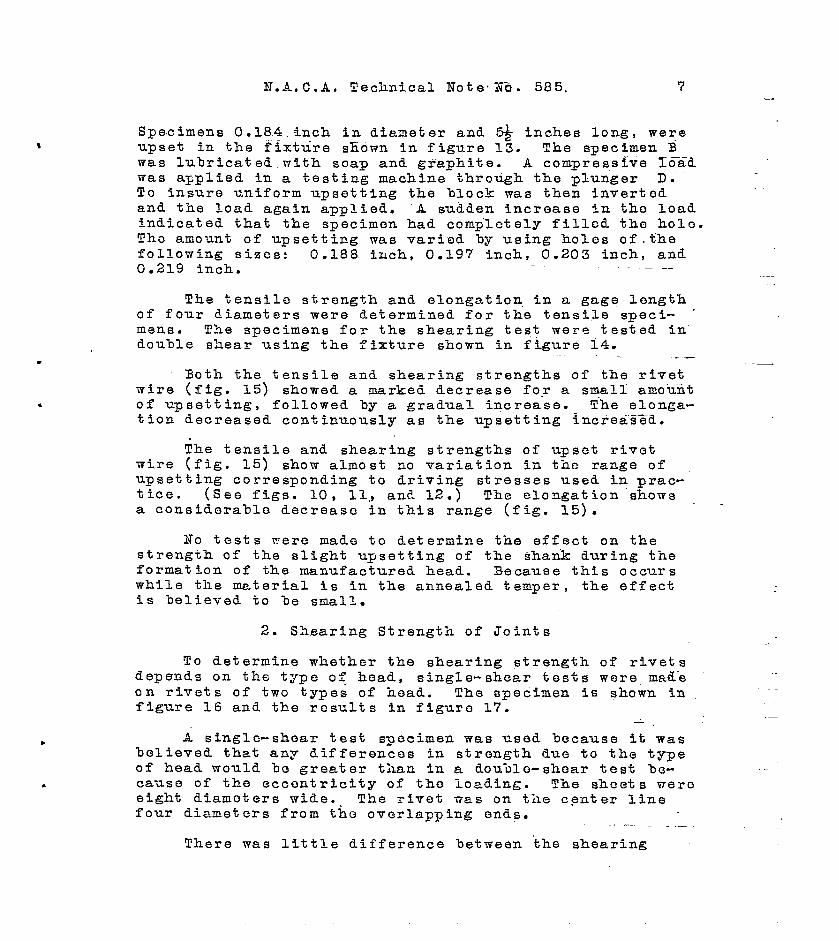
Specimens 0.184 .inch in diameter and ~ inches long, wereupset in the fixture shown “in figure 13. The specimen Bwas lubricated with soap and graphite. A compresslve””Toad
.——
was applied in a testing machine through the plun”ger “D.””To insure uniform upsetting the block was then invertedand the load again applied. “A sudden increase in tho loadindicated that the specimen had compl-ctely filled the holo.Tho amount of upsetting was varied by using holes of.thefollowing sizes: 0.188 iuch, 0.197 inch, 0.203 inch, and0.219 inch. —
The tensile strength and elongation in a gage lengthof four diameters were determined for the tensile speci- ‘mens. The specimens for the shearing test were tested indouble shear using the fixture shown in figure 14.
.—.Both the tensile and shearing strengths of the rivet
wire (fig. 15) showed a marked decrease for a small” amoi.liit. of upsetting, followed by a gradual increase. T-he elonga-
tion decreased continuously as the upsetting” increa”s%”d.
~he tensile and shearing strengths of u~set rivetwire (fig. 15) show almost no variation in the range ofupsetting corresponding to driving stresses used in prac-tice. (See figs. 10, 11, ant!.1.2.) The elongation showsa considcrablo decreaso in this range (fig. 15).
No tests -were made to determine the effect on thestrength of the slight upsetting of the shan”k during t-neformation of the manufactured head. Because this occurswhile the material is in the annealed temper, the effectis believed to %e small.
2. Sh,earing Strength of Joints
TO determine whether the shearing strength of rivetsdepends on the type o< head, single-shear tests were mad-eon rivets of two types of head. The specimen is shown infigure 16 and the results in figuro 17.
—
~ single-shear test specimen was used because it wasbelieved that any differences in strength due to the typeof head would lo greater than in a clou-~lo-shear test be-cause of the eccentricity of the loading. The sheets weroeight dtamoters wide. The rivet was on the center linefour diameters from the overlapping ends.
. ... . . _.
There was little difference between the shearing

8 N.A.C.A. Technical Note No. 585
strength of t-he“round and cone-point rivetis. The differ-ence between the results for the several d/t ratios wasless than the variation for individual specimens of thesame d/t ratio.
TO determine how the results of shearing testi forupset wire agreed with results of shearing tests of actualrivets, the shearing strength of thewiro after upsettingwas obtained from figure “25 and multiplied by the ratio ofthe actual cross-sectional area to the ~ominal area. !Chestrengths computed In this manner for ~ = 2.5 are shown
by the dotted liue in figure 17. In determining the com-puted shearing strength, it-was assumed that the effectof upsetting upon the shearing strength of the l/4-inchrivets tias the same as shown in figure 15 for the 3/26-inchrivc3t wire. The tensile str,ength of the l/4-inch wireheat-treated but not upset, was only 1.7 percent loworthan the strength of the 3/16-inch wire.
If it can be shown that thti shearing strength of ariveted joint can be determined by such a computation, itis believed that joints could be designed on a more ration-al basis than if nominal values were used. There are ob”vious &ifferences between the conditions obtained in thedouble-shear test of wir~ and those in an actual joint.Although a“ good agreement between t-he computed and ob-sorvod results is evident in figure 17, it is believedthat a further check of this agreement should be made onrivets under double-shear loading and of different diame-ters.
3. Tensile Strength of Joints
Although rivets are seldom intended to carry tensileloads, there are some applications where the tensilestrength of tho rivet is a consideration and where inf-or-me.t-ionregarding t-he strength of the head under tensile
load would bo useful.
Tensile tests were made of all the types of headshown in figure 1. As it was desired to test actual riv-eted joints, the form of specimen shown in figures 18 and19 was used. It e“onsists of two square sheets riveted to-gether at the center. Xach is fastened to one of theflanges (fig. 19) %y four cap screws. Holes to provideclearance for the’ screw htiads are drilled in the oppositesheet and flange. A tensile load was applied b~ connect-ing the flanges to the testing machine through sphericalbearings.
.
.

N.A.C.A. Technical Nate No. 585 9
Although the tensile strength of riveted joints de-pends on the design of the fixture and specimen, it isbelieved that the results obtained afford a valid basisfor comparing different types of head under tensile load.The results are plotted in figures 20,to 25, inclusive.The nominal cross-sectional area of the rivet was used incomputing stresses.
In general, for the lower ratios of d/t , the drivenheads pulled tlirough the sheet when the driving stress wasbelow a critical value. When higher driving stresses wereused, either the shank failed in tension or the headsheared from the shank around the slank circumference. Ex-cept in the cases of tho flat and brazier heads, all jointshaving a d/t ratio of 3.1 and greater, failed by pullingthe driven head through the sheet. . .
-All of the brazier-head rivets except those of the
highest a~t ratio failed by shearing of the manufacturedhead. The strength showed little variation with drivingstress, but increased with a decrease in the d/t ratio .The latter effect is probably caused by the IIdishingll ofthe .s-~eets under load. The effect of such &ishing in ashallow rivet head of large diameter is to bentl the shoul-der of the head away from the shank. The resulting con-centration of bonding stress at the shank contributes toshearing failure of the head. As the d/t ratio is in-creased the ‘tdishingll %ecomes more markea and higher %en&-ing stresses result.
--———
Figure 25 shows that the tensile strength of th~ flat-head rivets iS reduced if the aepth becomes too small dueto excessive driving stress.
The upsetting of the rivet shagk &uring driving pro-duces a considerable radial compressive stress in theshoots. If the driving etress is excessive this causesthe buckling and separation of the sheets already noted.
To determine whether there was a relation betweenthe radial deformation of the sheets and the drivingstress at which buckling occurred, moasurcrnonts of the ra-dial deformation wero made with the results shown in fig-ures 26, 27, and 28. ‘The specimen is shown in figuro 26.-
10 N.A. C.A, Technical Note No, 585
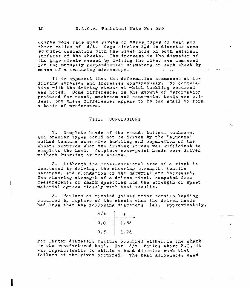
Joints were made with rivets of three types of head andthree. ratios of d/t. Gage circles 2~d in diameter wemsc%-~bed concentric with the rivet hole on both, emternalsurfaces of the skeets. The increase in the diameter ofthe gage circle caused by driving the rivet was measuredf-or two. mutually perpendicular diameters on each sheet bymeans of a measuring microscope. .—
It is apparent that the--deformation commences at lowdriving stresses and increases continuously. No correla-tion with t~e driving stress at which buckling occurredwas noted. Some differences in the amount of deformationproduced for round, mushroom and cone-point heads are evi-denti, but these differences appear to be too #mall to forma basis of preference.
.
VIII. CONCLUSIONS
1. Complete heads of the round, button, mushroom,and brazier types could not be driven by the llsqueeze’lmethod because excessive buckling and separation of thesheets occurred when the driving stress was sufficient tocomplet-e the head. Complete cone-point heads were drivenwithout buckling of the sheets.
2. Although the cross-sectional area of a rivet isincreased by driving, tihe shearing strength, tensilestrength, and elongation of the mat-ial are decreased.The shearing strength of a driven rivet, ‘computed frommeasurements of shank upsetting and the strength of upsetmaterial agrees closely with test results.
3. Tailure of riveted joints under tensile loadingoccurred by rupture of the sheets when the driven headshad less than the following diameters (a) , approximately,
d/t~
a——
2.0 I 1.5d
2.5 I l,7d
For larger diameters failure occurred ’either, in. the shankor t-he manufactured head. For d/t ratios above 3.l,”itwas impracticable to obtain a head diameter such thatfqflure of the rivet occurred. The head allowances use-d

N.A.C.A. Technical Note No. 585 11
.
in riveting the tensile specimens were sufficient to pro-vide adequate shearing strength of the driven head for alltypes except the flat head.
—
4. It was found impracticable to use measurements ofradial deformation in the sheets as a criterion of exces-sive buckling.
IX. ACKNOWLEDGMENT
The valuable assistance of the Aluminum Company ofAmerica in making available test results obtained in theirresearch laboratory is acknowledged.
x. PROGRAM FOR FUTURE TESTS
To determine whether the shearing strength of a rlv=-eted joint can be computed from the cross-sectional areaand shearing strength of the mater”ial after upsettiag,double-shear tests of riveted joints will be ma~e. Addi-tional tests are believed desirable bn rivets of other al-loys such as A17ST, 24ST, and 53SW. The contemplated testsof these additional alloys are confined to a determinationof the head dimensions and a study of the effect of upset-ting upon the mechanical properties of the shank+ A stockof rivets of the above alloys is being procured, also sheetsin alloys 24ST, 24SRT!, and alclad 24 ST.
After these tests are completed an investigation dftho strength of typical riveted joints will be made taprovide design data. -.
.
National Hureau of Standards,Washington, D. C., October 1936.

N.A.C.A. Technical Note ”No.585 IEg .r
b
.
Round Mushroom
1.75+
%
rI
~!0.751 /l
.,‘1 I
R=O.885+1~+t\ I //~-’-
Butt’on
1’-2”5-i
Brazier
“h“-1.5
k~ ~27”
0.’75J__} ! j
r,,
I..+ll O+-*
[
+’ ~: ,+: -in\ / \ I /’“-- ‘- r=
Cane oint Flat
Note- All Ltmensionsare in terms of the shank iiemter.—Lriven hea~s----- L!anufactureiheads
.. .
>
—
——. ._
—
.
—
—.
Figure l.- Types of iriven “headst=sted..—

.
.
.
*
Y.A.C.A. Teohnical Note No.5t35 Flge .3,3
Figurea.-Jigfor cutting rivet a-e to obtainmy &eslredgripandheadallowanoa.““&h notchA oorrespondetoonediameterofrivet(from1/16to3/8 in.).
Thelengthofthenotohes161 112timestherivetdiameter.8pacersB, eaohe~l to.di4,areinsertedundertherive’theadtoprovideheadallowanceslargerthan1 11~Whendesired.Additionalspaoers0,em tot~ettioknessoftheeheete,exesimilarlyInserted to obtainthegripallowanoe.Tighteningthethumbsoremolempstherivetbypivotingthe arm D ona rnovsblepin for which a 6eriee of holes, corresponding to thenotohen.3.EdrilledIn the baok of the blook
Tigue 3.-Jigusedtodriveriveteby the‘squeezef[methcd.Theloadlaappliedinahydrauliotestinguohine.TheholesintheendsoftheBpecircanarealignti
uiththerivethole- areusedtooonneotthespeolmentothetestf~msobinewhentestingthejoint.

. . . .
0.6
tal 2.0 Id.i1.4 1.6 1.8 .75 0.8 0.9 1.0 1.1
——._
-— —
.—
,——
—.
0.7 0..8 0.9 1.0 1.1 1.,2 1.3 1.4~al hlhl
Figure’.4.-Dimensionsof lrivenrmmdheals.I
:,., ,,
1,
I
ij

, . .
.9/d 2.0 hlli1.4 1.6 1.8 ‘-- 0.7.625 0.8 “ 0.9 1.0 1.1
=-a---
1-
1
~.3oo,oooa<5
I:
: I*m2fM,m0
gm
-1-~
—.:
zoo,000
Hcaid.iameter I ~ai d~pth I I o d/t= 2.0i!. n II= Z-5
I ii Zl”=3.1—
i
i I0. 8 I –.—l—————
0.6 0.7 0.8 0.9 1.0 1.1 1.2 1.3 1.4 1.5 1.6 1.7 1.8
Ia al hjhl
,i,’ l’igu’e5.- JiWn8iona of hiVeII mushroom heads.
~1,~:;: I
I II1:, ,I I

> . ● ✎
0.6 0.7 0.8 0.9 l-o 1.1 1.2 1.3 ~ ~ %i.5 K
all.75it h/o.75+3 . .
I?ignre 6.-UI
Dimensions of driven button heads.,: 1
,,,
II
,, ,i
,1,
I , [1~.1 I ,: ,1 \

. . 9 ,
1.5
I I
4oo,mJ –“—
I I
1’
1100, Ocn -—-—
a/3 2.5 h/d2
I
i
[
+-
!0.6 0.7 0.8 0.9 1.0 1.1 1.2 1.3 1.4 1.5 1.6 1.I
a/al h/1.11Figure 7.- Dbensions of Jriven brazier heads,
I:“. ,
I
7
l..

N.A.C.A.Technical Note No. 585
.
Fig.E!
1.5 1.6 1.7 h/d1.2 1.3 1.4 .75 .80 .85 .99 .951.0 1.05
300,000 --—,
[ i
II
cu.
\ 1) ,
..la
~ ~-. 1
.+
5I 200,0(-)0ul:
‘ “ %+ -
I&m
%’%-!b
.+ I I:100,000‘-cfs!- —L
II I,~.t --li
c1‘i
—
-—
.- .—
—.- —
. —.—
.— —
0 &/t= 2.0A “ = 2.5Ci “ =3.1
0.8 0.9 1.0 1.1 1.2 1.3 1.4a/1.53 h/O.75a
Figure 8.- Dimensions of .irivencone-pointheads.

. , .
a/d 2.0 II/d
1.2 1.4 1.6 1.8 0.4 0.5 0.6 0.7
300,000
CQ..2200,000
~.-❑
m0
3al
to lm ,000
d.l+z2,
~I o
0.6 0.7 0.8 0.9 1.0 1.1 1.2 1.3 1.4 1.51: /a Al hjo.4d
1.6 1.7 1.8
Figure 9.- IWuenslons of driven flat heads.i,
I

N.A.C.A. Technical Note No. 585
.
.
.
400,000
300,000
200,000
“m
3WI*.F1
&100,000
— — ..
.—
—.—.
0 1 2 3 4 5
——
F—
6dz ~—
—— . . -— —
d~.d.Upsetting, ._ ~a
Figure 10.- Upsetting of shank produced
6 T 8
100—.
by drivi~, d/t = 2.@

N.A.C.A. Technical Note No. 585
400,000
300,000
\Q“i-l
ii 200,0000
3d
.5!5
100,000
0 1 2 3 4 5 6
2——.‘7
Upsetting, d2- d ~loo
d
. .
..
—
—
----
8
Figure 11.- Upsetting of shank producedby driving, d/t = 2.5.

N.A.C.A. Technical Note No. 585
.
400,000
0 1 2
300,000
100,000
d--————.———.--H—L1 /
t~- ~~ “Mushr>om.
-—,Cone,. J
.— —
I 1d
/ /
-=3.1t
“-’J-.-–f--.——-— ._-\-—/ /
~“ ~ ‘
k.U1
+
I-.-— ,— .—. — .Ld’
~Ro d.
P
‘“~ -
t-~
!--.-—- ...-—— ..—.—
‘1—
3 4 5 6
Upsetting 32-d
dx 100
7
9
.—
IPigure 12.- Upsetting of shank produce~ by driving, i/t = 3.1.

. , I.
I
—
b.‘.a
rigure 13.. FIx*e for upuetting rivet wire. The inside diameter of
the splitbueMng A is eligbtly lar er tlan the epeoimsnb!B; the block C ODIItaIIM a hole Inwoh the bus w iB ol.ampal ard
rents on t:.? base E; the load is appliedbetween the plunger D amithe bnse E, .,
R@ure 14.- Double shear fixture for testing rivet wire.The @pecimen A is ineerted in holes in the
hardenul steel plates B (cuter) end O (inner) which areoonoaoted to the tasting maohine. The clearanc e between
the plates la adjuated to ap~rimately O.OEdby mane ofI the epaeers D. Wlao the outtiq edges at the Imles beoomeL mill they IWE nWPeUed by .refaoing the plates.
\

N.A.C.A. Technical Note No. 585 Fig. 15
o 2 4 6 a 10 12 14 .16 18 2Q
Upsetting, ~
.
I’igure15.- Effect of upsetting on mechanical properties of heat-treated rivet wire. Specimens were upset immediately
after quenching and agei before testing..- —“

. . b ● I
Figure 16.- Blngle shear mpeo5aen of riveted joint.Ths 10wUW IMB i8 oOIMINd in the
oOntLIOt BWM.9B Of th tpoi!d~ A WM the blooks B.Theee blookm me omnectai to the tmtlng mnoblnethrough spherioal b~lngs.
Figure M.- Fixtuze for tensile test
or rive%al joint.

. * ●
40,000 ‘I
~ L,+J$& 4-$--”I
Round head
30,000 H= 1.75d
m.
1
0 i/t= 2.0: A ‘1= 2.5>
*D “ = 3.1+ --. — Couputdi ekar~ng‘1$ strength for #t=2.5
brld: a,ooa ‘-‘——-
—.
+
~ -_ _,_ - ____ -----k
!
10,CKX3L
-t
!
0 -
0
I
,Iil
,1’.,,1
100,000
l?igute 17.-
i,,
IDriven head-cone.Mlfld II _r-~
H= 1.5d
——. --=
_L —.
2oo, om3 300,000 0 190,000 2m.3,m) 300,000Driving stress lb/in?
Strength of round and cone-pdint heed rivets under single- 4
&em loading.Pml
I .P<
I;;,.,’! 1,,”:,

.
.
N.A.C.A. Technical Note No. 585
/\Clearance holes
\~’an~body of cap
/I,
,,..
(g) @ (=J
\\
\ .
(Q)- ..
/2- \I\ () I
/-\ -- /--- f-
//-
//
. ‘\L,/
Fig. 18
for headscrew
-..—
--
..——
Figure 18.- !Tensilespecimen of riveted joint.

N.A.C.A. Technical Note No. 585 rig. 20
60,000
50,cmo
+.=2.0
2.5
-,
c
Al
(
i 3.1 !- 1
23,
10,
ooo~-l- ‘“~-:‘4-1—.. —
---1L-●
Round heati‘1 +H = 1.75 &
000 —.—. ~
t ~ i
-t
‘~,~-- . i-----
i 2. Shank (tensile)i 1 3. M’f ’d head (shear)
o 100,000 200,000 300,900 400,000Driving stress, lb./in?
Figure 2C.- Temile strength of round-hea~ rivets.

. # ● ✌ 9
.—
-— .—.
..—
Tensile strength,lb./in?Po 8. .
I.——.—.+.u)
+
— -.
wo-go
-d=—.-i
‘\
\\,
—— -—
.—
71T-
---Hw-bi-t+---
i :

.
4
N.A.C.A. Technical Note No. 585
&
60,000 II
$ =2.0
m, 000 ,/i
‘/
—I
m.c1< 40,000 /9“d
2.5~-
1
,.
;I /
Em 30,0003.I-l2E
I
20,000
t
“1w={17),, /
/
I 4.9{,
10’OOOl+t–‘--t-
-i—.
I
[1
/
L.
7/
-..——
I’ig.22-
>
t,
>>3
/ :
I
— 1..i_—,X’ II/’I
I
[
t--+-l---wI
/ II
Driven head-butto~ManufacWed head-ro&d
Failures1. 8heet(at hole)2. Shank(tensile)3. Manufactured head
o 100,000 200,000
uriving stress,
Figure 22.- Tensile strength of button-heafi
300,Oocl 400,000
lb./in?.— _
rivets.

N.A.C.A. Technical Note No. 585 Fig?.23
60,000
50,000
40,000
in
20,000
10,000
0
I
/
1. i—I i,
II I
.
r “34>—. .——
,a; =2.0 I
2.5 I~
I
i3.1
I
tIi/ I
# ,!!
Brazier Head
‘k
0’/ I
jH= 1.’75d— -—. —— .— .Failures
‘ ‘~
I$=4. :‘~ l.Sheet(at hole) I
2.ltanufactured I
hed(shear)
,7
I I
I If-
loa,000 200,000
Driving
Figure ~7.- Tensile str~ngth of
300,000 4oQ,ooo-
stress, lb./in?
brazier-head rivets..—
-—

N.A.C.A. Technical Note No. 585
m.d
<
~’
60,000
50,
40,
I
000F000
Ii
I- 30,0005$
.!2U-J
3d: 20,000El
10,000
0
1’
---4-1
$
——
100
Driven heafi,cone-pointManufactured hea~, rotid
\Hs 1.5 d. ,
I I(Failures ~
1, Sheet (at hole) i2. Shank(ten,sile) i
)00 200”,m 300,000Driving stress, lb./in?
.
.—
-. -— .—
—.
.—
---
—
Figure 24.- Tensile strength of cone-point head rivets.

Technical Note. No. 585 Fi~. 25
60,000
5Q,000
40,000
30,000
20,000
10,000
0
Failures’ I/
II
i1. Sheet(at hole) 1
–2. Shank(tensile) ~~f~~3. Manufactured head Y.4+
(shear) I1 ~//”
, 4. Dri.wen hea3(sliear) ~“
T-T/-
-i-!_L__J_J_J_100,000 200,000 300,000
Driving stress, lb./in?
—-—
.-.
Figure 25.- Tensile strength of flat-head rivets.

N.A.C.A. Technical Note No. 585 I?i.g.26350,Oc
300,Oc
25Q,Oc
m.G
-+00,00
100,00
50,00
o
/
RImnd .,
//
/— .—(/
/~1
I
II
I
~
t
/
--t+ —-
—Sheet surface atdriven head
— .—0.1 0.2 0.3 0.4 0.5 0.6 0.7 0.8 0.9
)
Average deformation in gage diameter, ~X’igure26.- Radial deformation produced in sheets by driving rivets,
d/t = 2.0.
—

N.A.C.A. Technical Note No. 585 rig. 273.50,000
300,000
250,000
.2g 150,000
100,000
50,000
n
J-’y//I
Round MUs:moom
~ y
-—
/
ConeA
— ——
d-=2.5t
.
I —
I I
._. Sheet surface at driven head
.—- - Sheet surface at manufactured head.
mLro 0.1 0.2 0.3 0.4 0.5– 0.6 0.7 0.8
Average deformation id gage diameter, $.
l’i~e 27.- Radial deformation produced in sheets by &rivingrivets, d/t = 2.5.
—

I?.A.C.A. Technical Note Note No. 585
250,000
% 200,000
y150,000
100,000
T—————,//
//
/
_QL__.–#
//
-#-,’‘//
~
//—/
—— —.——
L——.——.—.—.—-4--t
-.&-.,/”
/
/
-.
.:Musbroom
/ -–#YL1-
“’ I“”n-+
I
u
w
.—;-=3.1 It
,—
1I
It
—. ——
surface at driven head I——— . 11 II II manufactured hea~
\
I‘T’ i .-
0 0.1 0.2 0.3 0.+ o.5-- U.G o.7 008
Average deformation in gage kuneter, $
)?igure28.- Radial information produced in sheets by driving rivets,d/t = 3.1 —
![æ SHOCK ABSORBERS ¦ á í · ¦ 7 zf ¹ Æ Þ + æ ô # +f c o ± ¸r y ¨r ± ¸ y ¨r 9r qj * ð qj ° tac { ? qj Þ r qj Ù î { ? ? qj d Å ] 6 qj ¯ ¹ c ofr Ö h ¯ ¹ î](https://static.fdocuments.us/doc/165x107/606d809de29f9e072478b9f2/-shock-absorbers-7-zf-f-c-o-r-y-r-.jpg)


![(ZWWNHZQZR [NYFJ - abhishek-anand.comabhishek-anand.com/resume.pdf · \nym f ^wx j]ujwnjshj ns :. ij[jqtunsl 5wtçhnjsy 0st\qjilj tk =-921 -921 (fxhfinsl 8y^qj 8mjjyx (88 7jxutsxn[j](https://static.fdocuments.us/doc/165x107/5f01ca7d7e708231d4010d3f/zwwnhzqzr-nyfj-abhishek-anandcomabhishek-anandcom-nym-f-wx-jujwnjshj.jpg)


![ABriefIntroductiontoRayTracingand Ionospheric Models · 2018. 2. 23. · potential energy” [Marion and Thorton, 2004] Lagrangian Formulation Z L(qj,q˙j,t)dt =0 L(qj,q˙j,t)=T(˙qj)](https://static.fdocuments.us/doc/165x107/6095fc7435f16d6778597e57/abriefintroductiontoraytracingand-ionospheric-models-2018-2-23-potential-energya.jpg)


![Horario Abril 2020 - EMILIO VALENZUELA · &rohjlr (plolr 9dohq]xhod &ud %rjrwi-xdq &duorv %hoor $eulo d6f +rudulrv,qj 90 (& /+ 0dw &* (vs &5,qj 90 6rf 35,qj 90 & 1dw && 6rf 35 $uwh](https://static.fdocuments.us/doc/165x107/5f5c8fe268d67d4947799086/horario-abril-2020-emilio-valenzuela-rohjlr-plolr-9dohqxhod-ud-rjrwi-xdq.jpg)