Hoist Slings Considerations on the management of hoist sling.

MICHIGAN E'TAT.E HIGlihAY DEPARTl~ENT
Charlefl JA. Ziegler State Highwe.y Commissioner
PP.OGHESS HEPOH~' ON LOAD D!\I•'LECTION T.ESTS
DEALii:1G VH'TH LENC/rH AND SIZE OF DQ•,;ELS
}.!: ~ A. Finney
~~. 0~ fremont
Presented. at thE3 2?th Annual lVIer;ting of the Highi'ray He search Bo.:Lrd, h'ashington, D~ C.
Dc1cember 2--5, LJ,j,7
High".<.'-Y R<esearch Project ~;9 F'-1
Hesearch LB.borato:ry ~re::-;ting nnd Ht~senrch Div.i.r::ion
Report No . 104 November 21, 194'7

Introduction
Load Deflection Test Method
~re~3ting Apparatus
Ifiethod of Det(3rrnining True Helc;. tiv(~ Deflection
Load Deflection Characteristics of Dowels
Tc'3st Specimens
Qb-se:r.vation,fJ
Load DeflE~ction Characte:risticf;
Influence of Dowel Diameter on RerliduaJ Deflection
Rigidity of Load Tra.J:wfer Unito
Summary
Acknowledgment
B:i.b1iography
1
3
4
7
8
9
10
ll
12
12
14
16
17

F':i.nncy"-Fremont
PROGRESS RE:POHT ON LOAD DEFLECTION TES'rG m:ALJHG
kiTH LE:NGTH AND SIZE O.F DO·,iELE)
In 1934 the Michigan Stnte Hi.e,hway Dcopartment became v:Ltally in
terested i.n the problem of evcd.uatinr; load trancfer ~·evices and established
a comprehensive investic;;otion on this sub,j oct. The primary object of the
invest.i,gtltion was to devrc'.lop a tecrt method for evaluating load transfer
devices to the end that a d,,,finite spec:lfication for the selection and use
of load tranGfe:r devlces cordd be dt.rvclopecL Pro(~ress reports on the re
sults of this work no far hc:nte bee:n. published prev.iou~:1ly in the proceedings
of the.; Hi.ghway !lesrcar,·ch Board (l) (2) ::.
Thi3X'8 if? tmqu.r.;st:Lonably a g:ee•·:rL need at the p:resent time for such a
teAt procedure bec.sm.se of the continual nppoarance on the market of new
mechanical load transfer devices to replace tlHJ common clowol bar and also
becavse it l.s impe:cative that Vlfe kno·v.- the mecb,:·i.rLLcal c.nd physical charac-·
~eristics <Jf all typeB of lo_ad tra.J:H>ff;r devifJ~;I3 and cB.n p;oedict with
reasonable accuracy the perfo:rmr:tnce of such devicefJ under continual s'er--
vice, in order that they '""n be intelligently deld.gned and properly spaced
1.n a pavement joint.
The purpo;3e oJ' this paper :i.s to prenent the results of a pho.~3e of
thi,s investi,gation on the evaJ.1.v;rLion of load tr.s;.nsfer devic(;S dealing
sp~:cifically with the develoi_:ue:nt o_f u .lo.:~v.l d('!.flccti.on te~1t procedure B.nd
its use in stud;;Jn[; the rnechHnica1 cha:t'nc·li 1.:r:·istics and efficiency of
different types of load trE~ . .n.8fe:r dcviceB, eS}_)!3Cis . .l1y in respect to the
length and diEcmet<0r of dmwl bars,
("') See bibliography

Finney-Fremont
The study imrol ved the subjection of common dov1el be1rs of different
lengths and di.araeters embf.ldded in concrete blockd to she'll~ forces of vary-
ing magnitudes and measurJ,ng the r':lati ve vertical deflection of' the block
feces, The opening between the blocks being held constant at 1 inch and
1/2 inch. Three clia.meters of dowels used wen~ 5/4, 1 and 1-1/4 inches.
Lengths of 10, 15, 20, 24 and :'50 inches Viert;J in. eluded. for each dmvel dia
meter. Residual deflections under rr;,peated loads were observed and a
measure of load transfer unit '?tiffness, designated ,i oint modulus (shear
force 11 V" divided by true relative deflection "m") was introduced.
The recults of thiG work indicate that the length of the dov1el for
10 inches and greater length apparr::~nt1y har:; very litt1e influence upon
the d$flecti.ons of the do-ael-concrete system. The diameter of the dowel,
howeve.r, J.s definitely a contro11ing factor, in this respect. The 3/4
l.nch dowel is approximai;oJ.y J./2 as effective whereas the 1-1/~. inch dowel
has only about l/4 greatex' efficie11cy than the 1 inch doweL Under the
loadings of dtfferent ma;.;nitudes the do~rc-::1-·-conc:cete sys-tem assumes a re~
sidual det'lec:tion Vih.ich var.:i..es .in. amount for the different conditions
imposed~ The residub.1 dnf1ect:lon varies v,rith the do'Jwl diameter but for
the dovlel dietiitetero in.vestigatod, the 20 inch do~'ml length appears to
develop the1 lowest residual deflection value for different load values.
The work further :i,ncl:Lc;,,tes that the stiffness of the joint, (joint modulus),
is fairly constant fm· shear val11es v,ithin the norwal working range and
that there is a markable different in j o:Lnt modulus va.lues for each dia-
mete.r of dovielc It is believed th<:,,t r5uch a value E.tS joint modulus may be
succesefully employed as one crtteri.on in setting up performance specifi
cations for load transfer devic<''E'.
-· 2 -

.Flnney-Fremon:t
Further vwrk in this iri'Vestiga_tion is in pro§,ress do<~"JinJ; in general
with the performance of dowels and comrn,rcia.l load transfer device:l under
the continual action of repc,ated loads of magnitudes experienced on the
highways.
The report includes a descri,)tion of the load transfer device te,st-
ing mr.-.. chine and test procedure ftnd a discuseion of the load deflection
charact,,X'i_stics of the dovcel unitf! included i~1 tl10 study.
This test method_ is intended to detei'lni:~le Ct:~rtain mechanical charac-
teristicp of concrete and a 1oad tran::tfer dnviee when uBed in combination
as a t\tJ~uctural. unit. The results obtained Fill :)e used to determine the
required rigidity of such load tr~:.ns.fer devie0:s '.;;rhen used in a joint of a
conerete pavement for the purpowJ of establishing defi.nite spacing for the
units to acccnnplish, within specif:l,i;!d 1imi'tr:3, c.:tdequate stress relief in
the concrete and p:ee.vHnt faulting of tl:~.':;: slabs at th8 joint.
The test procedcn·e is urrlc,ue from the standpoint of other known
methods, published (3) (4) and unpub1ishecl (5) (6) (7) (B), in that it
permi.ts the testing of load transfer devices under known conditj,ons of
shear and bending movement. In thi.s particn:Lrcr case the type of loading
apparatus, si7~e o.f spccdmon, anci. specj_rnen 1oc-cd:ing arrB.ngement have been
arbitrarily chosen for convenience in conducting the tests. Other arrange
mentn of those features could no doubt be employed vlith ec;ual succeclS.

Finney---Fremont
Testing Apparatus
The testing apparatus iG comprif;ed of four distinct units: (1) the
machine, (2) loading ruoch.;1nism <:lnd sp~~·cimen supports:- (3) the auxiliary
equipnwnt for measuring the relative auxiliary dofloctions of the two
f3ec'Lions of tho test :-Jp(:;cimen in whi.cb tho load tranr·::fer device is embedded
and ( 4) the te"t speci.men. A view of th,c conrpletc t0st assembly may be
M§b.2l~.in~.: rrhe frame of the machine was specially constructed for this
particular work. A11 })arts YJC:;re ca:refu1ly cles:Lgn\?-d and fo.br:Lcat(~d to in-·
fJUre max.imum ste1.biLLty- with m:i.ntmum deflection and accorm:10date the test
specimen with all noce::Jsary mearm:c·ing dev:lcoG. As shown. in Figure 1, the
load is obtained by Ino&ns of a Iaanuall.;y operc:-t.ted hU ton hydraulic ram
mounted in sueh a mEUHlE~r that it may be moved to one Gide during the in-·
sta11at:1.on of the speetmeno Thc:re if.1 also ·provided <:.t short e.d~justable
eantilAver beam to which a hoist iG a'btaehed to faci15.tate lifting and
pl8.cing of the ;:-;pe.c:lmen on tho GUpport(~.
By meanE~
system is counterbd.anoed and, if deslr·ed, the load transfer dE;vi,ce may
be rmbj f>Cted to the a.etion of a def:Ln:L te bending movement in addition to
.c,l·.\F>ar ' • ] ~-..--r.)-i"'ll'iJJg- ·j·}J8 ')J'Oj.)C'Jo \;u.:·,·ig'Jtc: r t" s II o:-·J·dt! n n ~ _ ;_);y S.:UUp .y l.cJJJ: -'-,Y -.4. - ~~ J: ' - -' ,_,___.. l >-' C:t 1 "" .... 02 •
ThE:'l system 1·-Ja~~ a1so det::'lgned :Ln :;;uch a lllanner that the moment on
the load transfer devj_c;e cou1ci bu kept con(ltant ancl that the shear force
was one---baH' of the l.ond.

Figure~ L Apparatus for testing lo0.d transfer devices completely a0sembl.ed.

Finney-·Fremont
LQ.'!:Qilli0Viecban~J:illi: As illustrated in Figure 2, the load is applied
"to the specimen throu~Sh a dynamometer ring 11 A11 and special loading head
bridge "Bu and bea,ring memberG nB1 n and 11 .B~:n. A ten thousandths di~J.l is
mounted on the dynamometer· ring "A" to mearmr'' its deflection from which
the magnitude of loading is Q:eterwinud. La ter·nl displacement of the load--
ing head bridge "B" Ls 1)I'0'1Tented by rneans of the horizoatal bars 11 C11 ·'ilh:Lch
bear against the upright supportr: of the machine. The bearinr, member 11B 11 1
of the loading head j,s provided with a bnl.L and socket arrangement to effect
point loading on block No. l. of thcc speciJnon. Bearing member "B,.," exerts ""
full bea.ring acro,s.s blocl: h'o. 2 by meHnD of a ro.ller be0ring· arrangement.
S . 1 •. "D " . II l ,, . tl pecJ.a ouppor\iG 1
u.nct J2
vn · t a sinf~le roller on top and double
rollerG on the bottom are provided to insure fl'eedom of action in a hori-
zontal direction only. 1.'he rmppol'ts are aur:UJ''ied to be ri.gid in the verti-
cal direction •
.For th0: measurement of t.be angular deflect.lon of the blocks, level
bubbles 11 11 11 were mou:n'Led on the top ba.ru 11B11 , as shoYin ~.n _figure So
is to measure the reln,tive def1ectio.~ of the .fE:J.ce,s of tvw concrete test
blocks in Vlhi.ch a particular· losd tranGfer devi.ce has boen embedded and
subjected to predetermined J.ohdings. llu:::{iliary def1octions a:ce measured
in a clireet manner and the d~~si:r.ed d::;:f1t:·etions are ca1culo:Led from e::~tab·-
lished inter-·relat:Lons betvwen the auxiliary and desired deflections ex-
pressed by an analytical formula. Therefore, :Ln this particular test set···
up the auxiliary deflection:o wlll bs H;easured and the true relative de-
flect:Lon for an,y shear 11 V11 computed.
" - <.1 -

LOADING BRIDGE. AND SUPPORTS
EQUIPMENT l"t MEASURING AUXILIARY DEFLECTIONS
Figure 2
Figure 3

F:Lnney····l.~'remont
In order to m.easurf) the aUK"llia:ey deflections in this te~}t procedure,
a system of yoker~ C<nd bars he.ve been providm1 ae r5hova1. in Fi61.U:'8 5. Four
.specially deAigned dem01mtable yokes "A", two to each block, are attached
to the bl.ock.n by set sorews as shown in sketch. These yokes serve to
support the four dial bars, 11 B,H and 11 0 11 , two on each side of the specimen.
~ • II !!!I !I !J II -II II 1 d t Four cuals D-, D0 , D5 and D, are prov .de· o moasure the ap2ilia:cy def'lec--J.. ,:;;. L.J: .
tion of the blocks. The dialr.l are attached to the long top bars 11B 11 and
their stems make contact v1ith thG short lower bars "C". S..Lnce the top "B"
bars follow the movmnent of Block l and the lovrer "C" bars move with Block
2, the :celati.ve movomrmt of the two bloc;w w:i.l1 be reeorded by the dials.
Special lugs "F'" are carrt i.nto the sides <!f' the specimen blocks to
accommodate hand1ing d(:vices and to which tlm :3peGia1 parallel bars 11 En
are attached during the test to p:revent horiccontal d:lroplacement o.f the
specimen on the supports. The ends of thesrJ be.rs engage vri th the vertical
members of the; machine~ frame by means of Tollen3 11 G11 vvbJ.ch a1lovl'ed move-
ment in the vertical but no·t horizontal direction.
blocks each -~- inches long, 12 inch~-;r~ ;'tide E.t:od. ? :inches deep r;here nvn 2
is the r:idth of joint opening. The lolid transfer device is ineo:cporated
into the center of the two specimen bloclu'r during pouring operations, per-
pendi.cula.:r to the joint open:i_nf-, 1.md parallel to tho top and sides of the
spec:Lme.n.. The .i oint. opening may be of an:r desired width. The joint
between the speoimEm blocLs may be conr1tructed Hi th pr-ofa.bx·icated ;i oint
n.llel' matel'ial or left open. A rernov;:;bl8 joi_nt fonn is neces,sary v1hen
joint is open.

Finney--Fremont
Figure 4 shows the sp8cimen for)[, with load transfer device completely
assembled ready for r0ceiving concrete. Also note removable ,joint form
special lugs attached to fJide forms and J.on(sHudL1hl marking member across
top. The side fonns are securely bolted to <c ruachtned base plate to pre·-
vent loss of mixing water. The load transfer devices are installed exactly
as in a pavement project r,ith expam:ion shields an.d bj:t.uminous coating to
break the bond. Figure ~·; shorir~ ·mcth;d of cur.i.Ht .. tpc~cim~.:ns.
The various relati.onshi.ps between displacement of the b.1oclc faces and
auxiliary d.i.e.l movernrmt are derivsd in the fol.low:Lng manner with reference
to dimensional d:i.a.gram t;iven in FlcurCJ G and deflection dia&,ram illustrated
in Figure '/, The following ,,quat.ions may be N3tallll.shed for the compara.-·
tively small movements of the bj .. ocks \lhich t0.ke place under this t.ec1t
lllethod. 'rhe equations &.l'fl:
(1) (): ... " (,r + p ( ") cc pdj._.::;_9._dz :;; -·· f L
(2) d]_ ;:-~ q}3- (;{ t ( 13) Jl lL.J!.ldi - td2 -·
( 3) ( 0 '
~ f L d2 _ .. P6- 1-PFT -I -
( 4) m )' arz;· ('i) Y.•J ~ij - d;z ql_)- (.) ·-
L
(8)
Wh.ere u :~:· .! f
(9) True relative deflection m co m1 d1 + mz d2
~-J-hen w equal.s l inch ill]_ -· 1.00155
m;2 -- -0.0662.
':iben VI equals 1/2 inch m1 -- 1. 00135
--7-

Figure 4. Specimen form vdth load transfer device assembled ready to rt~ceive conc;r·ete.
Figure 5. Method o:f storing C3t)ec:Lmen during curj.ng period.

------------
15.43" ---~k>'?S'
DIMENSIONAL DIAGRAM 6
f
t q a w L -tp
~ Block I
Relative Deflection m j_
DEFLECTION DIAGRAM Figll.l"e 7

Flnney-Fl~emont
The computation of relative deflection "m" is arrived at in the
following manner: The dials are designated "DJ" and "D2" (front nide) and
"D:t" and "D2" (back side). The differences in dial read.in&;s "Ill" for both
sides in relation to initial reading;, for each load :Lncr·ement aro averaged
to give val.ue "dJ", and in the same manner the differences in dial readings
"D2'' are av,eraged to give value "d2''. The values "dl" and "d2'' are substi--
tutGd :l.n equation (9) to give the true rc;lativcl deflection "m" of the block
faces f'or any shear value "V".
In order to expedite the compilation of the tent data and calcula-
tions of the re1at:Lve block defl.c.;<~t:Lons, a f3pecial record sheet ·Nas pre-
pared as illm1trated in 'table .[.
A typical shear deflection di .. agram is presented in Figure 3. The
points a, b, c, etc. represent the sPear deflection values used in com-
paring the relative performance of the various dowel bar units, The resi.-
dual deflection values are :represented by the points at which the sloping
dash lines in.tersect the x axis or lhw of zero shear value.
LOAD DSF'LE:C'l'ION CHAhACTERISTICS OF DOWELS ~-----···-·--------,__.~....__.._._.,,_.....
By means of the testing procedure previously descri.bed, specimens
were cast and loc..d deflection tests conducted on .single units involving
dowel bars of 5/4 inch, 1 inch and 1-·1/4. inch in diameter and lengths for
81l.Ch diameter of 10, 15, 20, ;~4, and z;o inehes. 'I'he particular length and
diameter of dowels selected for this study were based on those now in
common use throughout the several States.
·-8-

--------------1/2 N C H J 0
16"4x 600 ~ OOWEL l...ENGTH 10 .. }-c;: ,.~-,
"' l \ \ -+------~ ~
X
u
z
2
z
0
~
u
~
~
~
~
0
100
J I ~ ~~~~£1 I =t7g:
3" I" , ..
t I" , .. 3" I I" E I
,. 4 l:o 14 4 14 4 14
D 0 w t L D I A M t T E R I N I N c H E s
EFFECT 1 DOWEL LENGTH and DIAMETER em DEFLECTION
3" ••
DOWEL LENGTH 30" .. __
7000
6000
5000
4000
30_0_0
----------1
Fi~>:ure 11
--i

TABLE I
TYPICAL LOAD DEr'LECTIO,N TEST ?.EC0;1D )F A LOAD 1'i'.AHSr'EF. DF.VICE:
----r;--.;;r---------------- -------------.---------------..-c=-RHF.AR . FRONT RID[ _BACK S~J2L__ #-· ..... '" ,.. _ 5 R Joint
LOAD fORCE AuxiliR Deflections in 10- 11 Auxilia Deflections in lQ-Str C.Ji.!PUlA'lJ.<)Nv IN 10 INCHEL f,Jodulus V Dial Diff. Dial Diff. Dial DUf. Dial _!._Our. r---d.i___ d2 -- Total J.l~.
lbs. in lbA D1 dl D2 d2 Dl d1 D2 d2 ave. m1d1 ave. mzd2 Def. m 1d8 lbs/in
0 0 527.2 so8s I ;woo 1000 5697 -125 6042
5550
-956 4284
5381 -~--+--~---+-~---r--+---
+1066 4824 +557 +320.5 +~20.9 -199.5 + 6.74 +527.7 +505.1
_ _:o:_+ __ o:__+_::5::_90::2:_-f-_-::63::D:_-t-:::6::27::5:_-t---::ll::8:::9'-t-''-'-""'o'--+--'-+90_2::o:_-t-::so::s::a:_-f-+312 + 145 .o +145 .2 -138. s + 14. a +ISO .o 0
_•::o~o::oe-t-2::o::o~o-1f--ss::o::oc_+-_-2:::2::8c_t-::57~-"::'c-+---::s9::7c_t-::'8::0::lc_t--•l::5::4::9Cf-044::3::2:_+-+-9c_•::g:_t+::G~6=o::.::s-t+~6=6::1::·::•-t•::l=2=6=.o~r--e'o·~'-1~+::6::5~7~.1~-·~'~04~·~•~
---'o'-+--=-o-1f-6:::1::8:::9-1f--:::9::17'-+-6::_5::7:::''-f--"'11B7 B9B2 +1368 4705 +676 +225.5 +225.8 -405.5 +13.7 +239.5 0
6000
0
0
10000
0
woo 5204 +68 5515 -429 5510 +1840 4199 +1182 +954.0 +955.3 +576.5 -12.7 +942.6 +518.3
0 6190 -918 6578 -1192 4608 +1712 4608 +773 +412.0 +412.6 -358.5 +12.1 +424. 7 0
0 6274 -1002 6666 -1580 3580 +1770 4450 +931 +384.0 +384.5 -524.5 +11.0 +595.5 0
5000 4662 +610 5052 +54 5081 +2269 ?i736 +1645 +1459.5 +1441.4 +649.5 -28.7 +1412. +353.9
0 6359 -1087 6688 -1602 554.<: +1808 4411 +970 +360.5 +361.0 -316.0 +10.7 +571.7 0
* For joint opening of 1 inch m1 =- 1.00135
* For joint opening of 1/2 inch m1 :::: 1.00135
* m = mldl +'m242
JoMo '=; m2 =~0.0662
600
U) 500 Cl z :::l 0 400 CL
w lj
·~ 300
0
0
0
0
d
c /. &-~ v ' / b/
m2 =-0.0338
~0 \oi\11;.,0 1-":71 /
;;::::: v " --: " "/ / ,.
v " / " ,~ " ' ,
" ' /" ~ 200
w I II) I 00
0
adZV / 0[;0:% / v ,./'
/ /
0 4 50 0 10 30 0 20 60 70 80 90 100 110 120
DEFLECTION IN INCHES lo-4
TYPICAL LOAD DEFLECTION DIAGRAM
lov 14 0
Figure 8

Finney -li'remont
Two complete serie<J of tests were j)erforwed for each length and size
of dowol, one with a :Jpccimen joint op8ning of l inch and tb' other at 1/2
inch. The 1 5.nch dimension was selected to simulate thfl expansion joint
opening employed in lVlichigs.n. The l/2 inch openi.ng ·"ms introduced in the
study because it was beli<JVed that l:!11der extreme conditions such an openint;
would occu:r at contre,ction joints cree,ting the 100 foot continuous pavement
slabs such ~s no~·v considered in lviichig~.:tn' s concrete pavement desig::n
practice.
Test S11ecimenn ---·---:.;..../.·-·--The specimen~i ·were cast ir~ the m.s.nne:c previously described under
testing avparatus emp1oy1n~s tr,e open jo1nt nw'thod.. Three specimens consti-
tute a test on eD.ch size of dowel. All specimens were Cl~red 24 hours in
the mold vii th wet -burlap covering, then 6 days out of the mold in a moist
room and te.sted at ? days. '.L'he strength of' the concrete was determined by·
pa:ca1lel compression and £'1exural tests on speeimens cast :from the same
concrete use0. in c<::tsting specirnens.
An attempt wail made to J.nsm:·e the samE' qnal:L ty of concrete in all
specimens. The Portland cemcmt used c~onformed to ';ur:rent specif'icat:Lons
A. S. T .l'v1. DefJignatlon C··-150, rrype I. 1rhe coarse and fine aggTegates met the
Department's grading and phynical requirements respectively for 6-A mate-·
r:i.al and natural sand 2-·NS as spt;cif:Led for pavement concrete. The coarse
aggregate consisted of gravel from Green Oak, Michigan. The sand a.lfJo came
from the same sourcu~
F'i.nney-F'remont
The concrete mixture was designed in accordance v:i th the hiiortar-Void
principle employed by the Department. 'rhe mix design nas based on 5. 5
saclw per cubic yard, 5.45 gallons of water per seck of cement, which pro-·
due cod an average compression strength o.f approximately 3, 000 pounds per
square inch in 7 days, 'I' he consistency of the moisture was held to an
average of 1-1/2 inch c:lump.
The steel in the do11el bar units nmt the requirements .for inter
mediate or hard grade steel of the Current Specifi.cations for Billet-Steel
Bars .for Concrete Reinf'or(:emont, A. S. 'r .M. Designati.on A-·15. The respective
ultimate tensiln Btrength cha:ractorir;tic:.l of the steel VJere 96,755; 84,185
and 86,920 pounds for the 3/4 inch, 1 inch D.nd 1-·1/4 inch diameter dowels.
In order to duplicate .field conditions, each dowel received a com-·
plete coating o.f aBphalt cut-back material (HC-··1) before tha concrete was
poured i.n the i3pcc:Lmen mold.
Qbserv~~i~
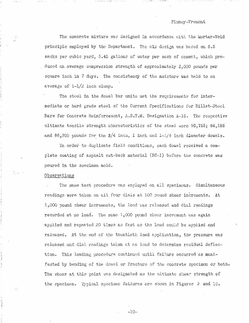
The sarne test proceduTe nas employed on all specimens. Simultaneous
readinge were taken on all four di.alB at 100 pound shear in(~rements. At
1,000 yJound shear incremr111ts.9 the loalJ. van released and dial r·e&dings
recorded at no load. 'i.'be same 1,000 pound she.•ir :increment r;as again
applied and repeated 20 timea a\3 fast cw the load coul.d be uppU.ed and
released, At the> eml. of th<' "tVIEmt:Leth load tJ.pplicati.on, th<o pressure was
released and dial reading/3 taken at no load to de"terrni.ne residual deflec-·
ti.on. This J.oadi.ng procedur<o contim.:.Cc;d unt.i.1 failure occurred as mani.
.fested by bendi.ng of the dowel. or fracture o.f the e0ncrete specimen or both.
The Bhear at thin point vras desisnated af:; the u..l.t:i.mate shear strength of
the specimen. ~ryplcal spec:Lmen failures are shov,m in Figures a and lO.
-·10-··
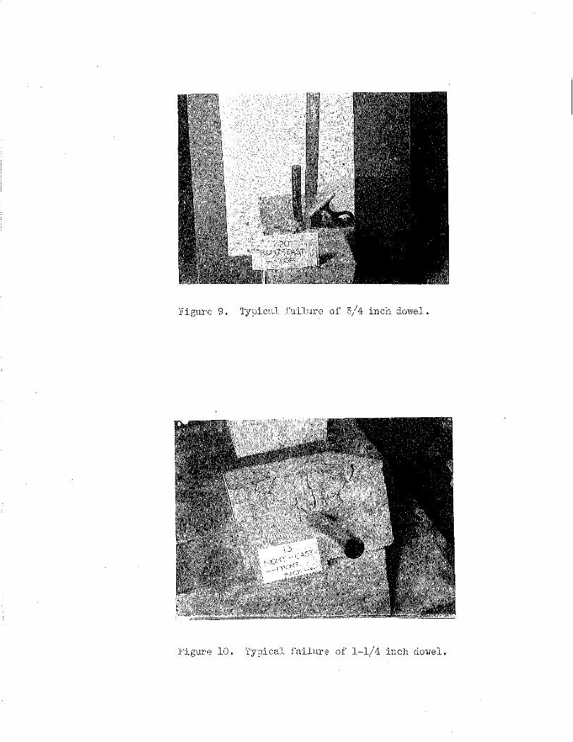
Figure 9. Typi.c1:cl .fa:Llt.lre of 5/4 incil dowel.
Figure 10. 'fypical failure of 1-·l/4 inch dowel.

F'1nney-.Fremont
Although speciaJ precautions were exercised in an att;;:mpt to insure
concrete of unifo:cm strength in all specimens, there prevailed a noticeable
variation in compressive strength a.s indicated from the test cylinderS.
Average specimen Dtrength waB approximately 5500 pour.tds per sc1uare 'cnch.
Subsequently, an:? marked variation in concrete strengths was l'eadi.ly
detectG~d. in tb~.:J deflection va.1ues from t.he specimen loading tests~ The
reBults of spc:;;c:i.rnenf~ obvious1y out of line of concrete strength and defl.ec-
t,:Lon value~: were discarded and. 1~e~" ~~peclmenB wer(3 prc~pared and tested.
The to sting pro~ram had a threefold pur.pose; f:i:f.'st, to obtaj.n :re1i-
able data in order to e{3tc~bli:sh satlsfactory load de:f:'1ection characteristic
curves for dowels of d:Lfferfmt J.e,:.lgtbs and. dj .. :::tmeters; ~J8cond, to cornpa:re
the re~;idual deflection cba.ra.cteri~~tic:s of the :i.nd:l:~ddual d.owel urdtsj and
finally, to develop 1nforrue.tion on the rigidity charc.ct.eristics of the
dowel-concretE: system, all of Hh).ch r:ould be directed to~eo.rd the nolution
of the load transfer problem~ A sunnnrtry of test data is presented in
Tables II and III.
rr:he load dG.fl.ecti.on checracteristics for the various dowe1 units at
.i oint openings of 1 inch and 1/:.2 inch B.re pre"1unted graphically in Figures
.} .. 1_, 12 and 1?... T.he curves in :F'igtn·e~3 11, 12 and 13 represent the relation-
;.~hip between eheB.r force, deflection, 1ength and cU.ameter of dowels for the
t ' . t . . d" i .. 1 . h . d l •. , . h VlO J oln spacJ.ng- lS ~ancE::e oi. J.nc an .. / ,:., .LllC .
curves is an average of three te;..:::t, values.
-11~ ..
Each point on the

TABLE Z
SUMMAB.Y OF AVERAGE TOTAL DEFLECTION, RESIDUAL DEFLECTION, AND JOINT MODULUS DATA FOR DIFFERENT LENGTHS AND SIZES OF DOWELS AT JOINT OPENING OF OIIIH!ALF INCH
Units ror O..f'leotions a lo-4 inches, Joint liodulus = lo3 pounds per inch
DIAI!ETI!R " 3/4 INCH D±IilitfER : 1 INCH ~~~ --
DUliE'l'ER : 1•1/4 INCH SHEAR FORCE
Pounds L·eDgth LeDgth LBngth 10 15 20 24 30 10 15 20 24 30 10 15 20 24 30
1000 Total De.f'leotion 57 52 43 61 47 37 42 28 38 30 26 20 22 28 37
Residual De.f'lootion 16 16 -2 10 20 15.1 14 11 19 5 12 5 9 15 26 Joint Modulus 175.4 192·3 2)2.6 l63o9 212.8 270o3 238.1 357·1 263.2 333·3 384.6 5oo.o 454·5 357ol 270·3
2000 124 127 123 133 99 76 80 51 78 50 49 48 44 53 71 86 21 ll 27 4l 31 22 16 20 9 21 17 18 21 35
232.6 l57o4 162.6 160.4 202.0 263.2 250.0 392.2 2$6.4 400.0 4o8.2 416.7 454.5 377o4 231.7
3000 239 202 207 263 167 115 132 80 123 87 70 83 69 81 112 110 28 14 47 53 49 34 23 33 10 31 30 24 26 44 125.5 148.5 144.9 114.1 179.6 26oo9 227o2 375·0 243·9 344.8 428.6 361.4 434.8 370.4 267·9
4000 337 302 292 391 247 154 175 111 175 122 96 117 96 112 149 154 38 26 85 66 68 40 26 40 12 . 33 44 32 29 46 113.6 132o4 137o0 100.8 16lo9 259·7 226,6 360.4 228.6 327·9 416.7 34lo9 416.7 357·1 268.5
5000 541 424 430 551 353 205 225 144 226 165 126 151 135 144 183 253 28 35 99 95 78 47 35 44 13 39 53 33 35 47 92o4 ll7o9 116.) 90o7 141.6 243·9 222.2 347.2 221.2 30).0 396.8 3)1ol 370.4 347.2 273.2
6000 ~Sl 60$ $41 680 441 254 283 186 288 211 l6o 191 158 17~ 227 387 72 17 122 lOS 49 53 $5 14 50 92 40 40 53 lo8.9 99ol ll0o9 88.2 1)6.1 236.2 212.0 319.1 2o8o3 284.4 315·0 314.1 379·7 342.9 264.3
7000 600 330 359 236·5 362 265 2o8 233 184 224 259
1)0 52 36·5 72 13-5 39·5 125 48 44 57 116.7 212.1 195·0 296.0 193·4 264.2 336.5 )00.4 380.4 312.5 270·3
Ultimate Shear in lbs. 6000 6500 5667 5917 6417 8750 8633 8083 9750 9250 9833 9167 n,ooo 9667 8167
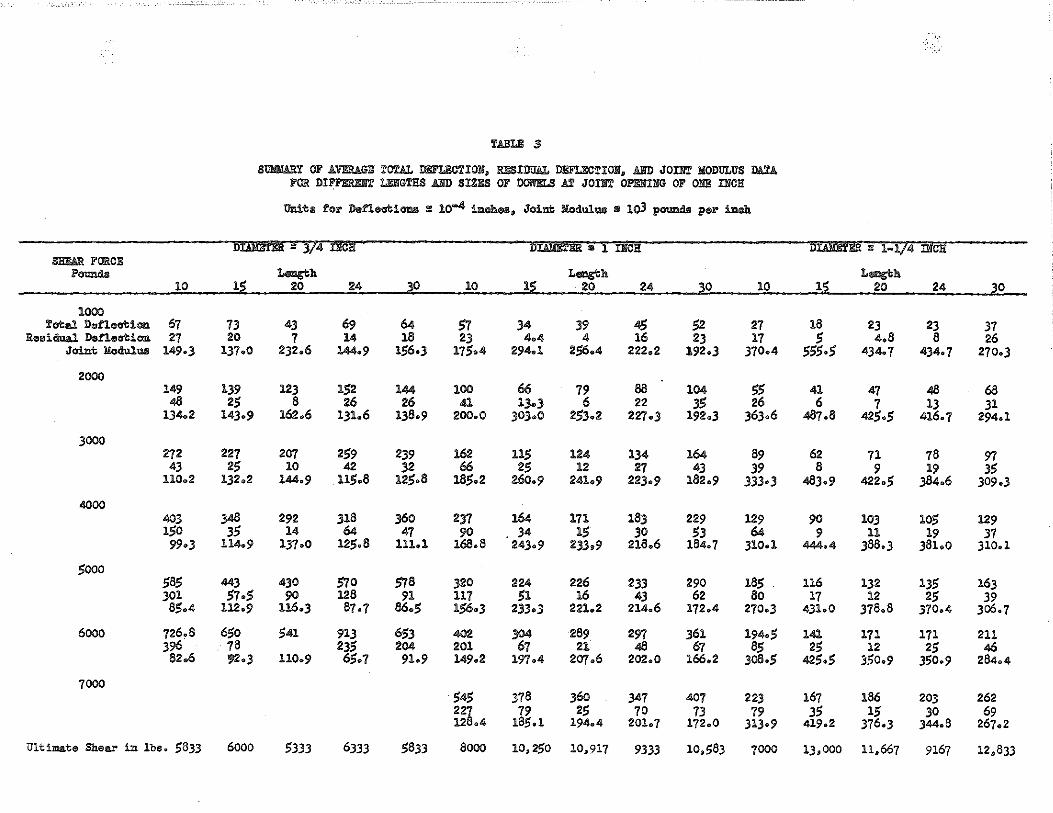
TABLE 3
SUii!WtY OF AVERAGE TOTAL ll!!FLI!OT!Oll, l!liSIDUAL DJ!FLECTIOII, AliD JOI!l'.r IIODULUS llAU. FOR DI>:F!i:Rl!ll'.r LI!IIGTRS AliD SIZES OF llOI!ELS AT JOM Ol'EIIIIIG OF Ol!ll! !IIC!i
Unito for Defleati""" : 10-" il>oheo, Joint llodulWI Ill 1o3 pouncls per iDch
DIAitfBk = 3/4 iicR D±AliE'I'Bk " 1 !IICI! llliliE'iER : 1-l/4-DICI! Sl!lW! FORCE
l'ouncls LI!I!Jgl:h LI!I!Jgl:h LI!I!Jgl:h 10 1~ 20 24 lO 10 1~ 20 24 lO 10 12 20 24 30
1000 Tatol Deflect:l.cn 67 73 43 69 64 57 34 39 45 52 27 18 23 23 37
Reoidual Dof'lect:l.cn 27 20 7 14 18 23 4o4 4 16 23 17 5 4.8 8 26 Joil>t llodul"" 149·3 lJ7oO 2)2.6 144.9 156·3 175·4 294.1 256.4 222,2 192·3 370·4 555·5 434·7 4)4o7 270·3
2000 149 139 123 152 144 100 66 79 88 104 55 41 47 48 68
48 25 8 26 26 41 13·3 6 22 35 26 6 7 13 31 134.2 143o9 162.6 1)1.6 136·9 200.0 JO)oO 253.2 227·3 l92o3 363.6 487.6 42_5,_5 416.7 294.1
3000 272 227 207 259 239 162 115 124 134 164 89 62 71 78 97 43 25 10 42 32 66 25 12 27 43 39 8 9 19 35
110.2 132o2 144.9 .115.8 12_5.8 18_5.2 260.9 24lo9 223·9 182.9 333·3 483·9 422._5 384.6 309.3
4000 403 348 292 318 360 237 164 171 18.3 229 129 90 103 105 129 150 35 14 64 47 90 . .34 15 30 53 64 9 11 19 37 99·3 114.9 137·0 12_5.8 1llol 168.8 243·9 23.3.9 218.6 184.7 310·1 444o4 ,388.3 381.0 310.1
5000 585 443 430 570 578 320 224 226 233 290 185 116 132 135 163 301 57·5 90 126 91 117 51 16 43 62 80 17 12 25 39
8_5.4 112.9 116.) 87 ·7 86.5 156·3 233·3 221.2 214.6 172.4 270·3 4)lo0 378.8 370.4 Jo6.7
6000 726.8 650 541 913 653 402 304 289 297 361 194o5 141 171 171 211 396 78 235 204 201 67 21 48 67 85 25 12 25 46 82.6 ~·3 110.9 65.7 9lo9 149.2 19'7o4 207.6 202.0 166,2 )o8o5 425o5 350o9 350·9 284.4
7000 545 378 36o 347 407 223 167 186 203 262 227 19 25 70 73 79 35 15 30 69 128.4 18$.1 194.4 201.7 172.0 313·9 4l9o2 )76o) )44.6 267.2
Ultimate Shear iD 1be. 5833 6000 5333 6333 5833 aooo 10,250 10,917 9333 10,1)83 7000 1),000 11,667 9167 12,833

1/2 I N C H J 0 I N T 0 P E N I .. -~ J' -~
~I
fl: I ~~~-r-' -~
--+-- 1-~ I
',
lUI , ·~--l I ,
_L !
i --~-'
I
---- -- ------ --·---~ --------- ------- --------
N G I !
I l~/z; -~-i----;----'----+'4~ --~ ~· ~~ '
i : ~<~ i /~I
ldr-/ r I
00 100 200 300 0
, ~-vI , , : rfP ' j ,
,;,:; I 1 v 1 l j !
100 200 300 400 soc eoo 100 eoo 900 1000 x ro-4 100 .200 300 400 500 600 0
DEFLECTION I N INCHES
EFFECT of DOWEL LENGTH on DEFLECTIONS
F'OR DOWELS OF 3/4~ DIAMETE:R
Figure 11

-· 10 X
~
w
I
<)
z
z
2
0
~
<)
w
~
~
w
0
1/2 I N C H J 0 I N T 0 P E N I N G --------···-- --~1
1000 ~------ -- T -- -- ------ r 900 -: INCH DOWEL , -----~ 1 INCH DOWEL I~ INCH DOWEL
800
i 700
600
500
_/ "" :;:- -. / """' -...........! I/
-
' SHEAR F'ORCE LSS. 6000
---
-~
--I
~---
'
400 ~" -----~- -- 1----
./ ~' --- - - c... - --- - -- . - ----
500 -200
100
1000
900
800
700
600 ~
500 """ -........ 400 ---.;.__ 300 -200
100
0 10 15
_ ........ -5000
4000
3000
2000 1000
........ /
::----......"' / ...::::::-: ~
INCH JOINT
~ :---::: --SHEAR FORCE LBS. 7000 6000 5000 4000 3000 2000 000
OPENING
~ INCH DOWEL , ""' 1 INCH DOWEL -----~1! INCH DOWEL
' /1 I.
. I -- / /
i
""' =
=--=1
SHEAR FORCE LBS 6000
5000
4000
--t:---~ 3000
2000
000 i
I
20 24 30
LENGTH
1----
1----!'-.
~ ............... _........_
10 15 20 24
0 F D 0 W E L
::::::--SHEAR FORCE LBS. 7000 6000
5000
4000
000
2000 ;
000
30
1-
10
I N INCHES
-
15
EFFECT cr j DOWEL LENGTH and DIAMETER em DEFLECTION
fa!? JOINT OPENINGS a-j 1" aadl/2"
20
I
I ' ---: '
-I
'
---------.
'
24
--=
' '
30
SHEAR FORCE LBS. 7000 6000 5000 •goo 3 00 2000 1000
SHEAR FORCE LBS. 7000 6000 5000 4000 3000 2000 1000
Figure l2
I

r----- ---------------------------1/2 N C H J 0 N T 0 P E N M G
, .------------
10'4x 600 ~ DOWEL L~NGTH 10" t
~
"' X
u
2
2
N T 0 ---- ---....1
z
0
~
u
"' ~
~
"' Q
1=-~ t I 1999~ r=--:=r ~~~; 3 ~ [ \ ~
l" jl~ ,! I" 1.!:' ,!" I 1J: .A." I 1.!:' A." I 11" 4 4 4 4 4 4 4 ~ 4
D 0 W E c D A ... E T E R N N C H E- S
EFFECT of DOWEL LENGTH and DIAMETER an. DEFLECTION
Firor" :13

F'hmey-Fremont
Considering the limitations of the test procedurE', the results
obtained indicate -tbat; flrst, within the normal load range e:"pected on the
pavement, the length of the dovml has very J.i ttle influence on deflections;
second, the diameter of the dowel greatly influences the deflection, but to
a much J.esr:el' degree as the diarntrt.er exce('lds 1. inch; third, dovi'els have
grea.ter rer::lst.ance to def1ec·~ion as the ,joint opening decrease;:1, but a
change from l inch to l/2 ineh v:Ew not sufficient to develop markable clif-
ferences in def1ection. valuos.
As mentioned previ.ously tmder tr,c:t procedure, 20 repet:itions of'
loadings Nere made at Aach 1,000 prmnd shear increwent, and at cessation of
repeated loading tho deflection at no load wa.s recorded. It VIB.f' thought
that such a loading procedun" might give so)ne indication as to tbe relative
efficiency of the variouG cloHe1 WJits ttndc1· re::Jeated loads. 'D1c~ residual
deflections resulting from these tGsts are summariz.ed in Tables II and III
and presented graphically b~y eurves in Figur;;; 14.. The d.ata. bring out the
inherent weaknes;; of the 3/4 inch dowel in th:Ls respect and for low shear
values there is very little di.ffereneo between the 1 inch and 1·-1/4 inch
dowels. It is logical to r;cxpoct, hovcevor, that ·the 1--J./ 4 inch dowel should
have a lower residual deflection dwa to its greater bearing area and stiff-
ness as cmapared to dm·rr:lD of 1t?.fl:3er c1iameter.
The stiffnesB or rit:;idity of load trarwf'<er davices may be Eixpressed
by a physical quantity proportiomrl;;, to the shear forcu and inversely pro-
portionate to the deflection ·Hhi.ch JD ex.pressed by Y.. Vihore11 V11 is the shear
111
force i.n potmds and in the deflection of the un:it :Ln inch0s. This
expl'ession has benn termed the J'oint ?Jodulus ~

• " • u
z
z
z
0
" u
" " " " c
OPEN NG ----- --- - . ' ' c " _o_o -'-( r_ r
,,_cT _ _ ~~~ .. ~ I "' )~I '~u--, ,, ---t- I - +- -~-----· - - ·r' --
"0-~\- -~- - I l'-+ -~ -~- ·~· '"
'"
0
164x 300
250-
'"
'"
100 -
50
0
1 .. +----- •
OOWEL OIA~~) ~~ _f -
" " " 2S 30
0 0 W E L
t "" --t--- +~;:~ -- l' I
~ 2&= NCH JOIN OPEN IN
+-c:?/;ooo
" " " 2S 30
LENGTH I N
I f-1
L
"" J
/ "'"' ~ 3000
, / /.zooo "y / /)000
/_//"
.! " .!
T
~~~--- -----------:
T l )oo~oc "' . -~ METER,Il/4"1 !
/;ooo
"""' 3000 I '- '-. - .. {>C/2000
.. ------r------" .. < / ./ /1000
" " N C H E S
, __ _
" 2S
--, T
30
EFFECT ~~ DOWEL LENGTH ~w. RESIDUAL DEFLECTION
Fl.gure l4 ===============================

JJ'i:nney---Yremon t
rigidity of the dov;el lll'L~ ts for d:i.fferent ~..~onr~1.it:i.onG are c<\.ca.··,ly C.efined.
r;rhl~:l is gr~:tphical1y illustrated :l.n Figure 15. 1:rhe d(.,_t:J. shovi t-,hat 'iJ":LtJ:-.d.n
reason<J.bl&; load lirait;-1 the .i oint mcdu.~.u;-3 for tile differemt dcn,:e1 units
remai:1s fairly confrLant. Tld"'g bein~ true, it wou1d appear the.n that sueh ,:~
physical ve,lue a~-; ;i c:l.rrt. mr.;dvJ.utl could bd sune(:)GSful1y ernp1oye3. as one of
,:;·everal c_!"'itn)ri.n. nc-;cessar;y f'(;:r f3t:d:;·1.:.int:; up perforrm-J.ECe specifications and
for c:rea.t:ing eoinparative ntUYl(h.:~·ds for use ::.n r7.vnluating c0mmercie.l load
t~canEf(-:;r devices vr-~r~~tw dmiml barn
·-1:3--

(----------1
103 I( 700 \---,---,,---,----~----112
600 ::r 0
z 500
400 a:
"' .. 300
.. 0
200
z
" 0 100 .. 0
z
I I I I I ( D1
0WEL DIA. ;~·'' }--
f----+---I ,
I
~~~----l· ... -~ :~~~--_J ~· 4'---_--"::'-.r~---t---== ~ - ..... ---- ·---
15"
I N C H J 0 I N T 0 p E. N I N G
. r -r---\\ __ _j,l ' ' '~ ~a•<>•~
.-_Y_?~-
I
l I
-
DOWEL OIA.
--f
r-------------------- -- -- ----------- - - -- - -- ---- -- -- -- - - - -- -------- -- - .. -- -- - ---- --- .. - ------ -- -- -- ------- - --- ----,
60• ., " ..J
" 0
0
500
' "' 400
300 ' >-
z I - 200
0
, 100 '
'
1
0
24"
·-· 1000 -·· 2000
s
r .. DOWEL OIA 3~~ ·•
-----
F-~· ---·· --
~ ·-· 3000
H E
~ ........ 4000
A
5000 0
R
I N C H J 0 I NT OP.ENING I
r
I I , I
C\~j 24" ! j 1--- -t ~.· ::. . -_J_·_· -~ -~ -==--::-=======: ------- --- - ---
)000
0
)Ja I
2000
R c 3000
E
4000 5000 0
N p
, . ·--T- --; I. .. ~~ ,,. ·1h.· ~·· ___ i ..... - . ·-........., ·=· -. ---J , .......... i , -- I
! : . .j
-- ---:--~= --::: ____ ---- ----- -------4
>000
0
2000
u N
5000
D s
E F F E C T "f D 0 W E L L E N G T H "n J 0 I N T M 0 D U L U S Figure 15

Fi..nney--F'remont
Vle Go not ret~arcl the resu.lt:.; of tl1i~J st\:tdy as conclusive, but Yte feel
that sufficient evidence has been add·u.c'ted to warrant recot,n:L tion of a load
deflection test proceclure for the purpose of evaluating load trar1sfc3r
devicee in order to prepare specificatlon~l for their pe:rfonilance and use,
and to determine basic information necessary to advance the design and eon-·
wtruct:Lon of' transverse j o:Lnts in concrete pavements. Significant. fi.ndingr>
of this study ar·e:
l. No EJign;Lf:Lcant. re1E.:.tJ.onship exists betwnen length and
relative d,oflection of tl.t8 do'Nel-concrete 'wstem.
2 ~ DoYre.l diam.eter is tl1e most important factor in Gontro11ing
deflection, DLr.J.mete:rr:; loss than 1 ir.tch are relat:Lvely
ineff.::;cti ve j,n c.ontrol11ng deflcctionf; under normal shear
loads., On the other han1.1, dov1els \·ti th dicu:ae"ters greater
than 1 inch tend tn r1 .• ptu.re the concrotr;_~ bef'o:r-e falling in
flex-ure.. This would ind:i. cate the need for con~Jider·ing
slab thiekness in rele:ticH'l to dovwJ dia.meter.
5. For sindJ.[J.l" 1otcd conditions thu residual deflection of
dowels diminishes 1;1ith incrt~ase in d.oYre.l diameter, but
a.ppc?a1·s to be at a miniml)Jn amount ror d:y,.;el~) of .20 inches
in lengt.h irrespective of dir.un,Jte:c.
--14·-

:F'inney--Frmuont.
4. ~rhe stiffness o:r rir_~idit~y of J.o<..1.d transfer JevJ,ce~3 may
he exprerwed by a physi.cal c1ual:Lty proportiomcl to the
shear force and inversely p:ropm·tiona]. to the deflection
termed the J oj,nt Mociulus and oxpreGst~d by Y~ The joint m
modulus for all prnctical purposes and vli thin reasonuble
load values mLty be considel'ed o. con[;tan t vc~luE.~. Data
incli .. cates t:he possibLLity of using such a value for
compcn:·:Lng the ro1c~ti V 13 eff:i.cic;)ncy o.f load transfer units~
-·15--

Finney-Frerrtont
EJinco the baekground of expe:cieuce arwociated wJ.th this study dates
baeJ\: to l:JM, and the :Lnvc"stig,~tion haf; been perj_od:Lcally V~orked upon and
developed during the interim, :Lt .i(J diff:Lcult for the authors to specifi-
cally acknowledge JndebteclnfJSS to dJ. persons concerned. Acknov;ledgment is
mad~:: 'to J. ~ ·w. Kush:Lng,:~ former Hesaarch an.d ~.eenting Bn[:·int~e:c .for the
De;Jartment, 11ho or-g,,_n:Lc.ed the invep,t:i.gation in 19:-14 and did much to develop
the test procc;dure _; to L. ll. Childs, ?by:sical Hec·oa1.'ch Engineer, for
assistance in Pl"r~pc-.ring the report; to Paul :I'Ceiffe;:, Physical Hesr-;arch
Engineer, for supervising the tc~sting and lEtboratory Tmrk; and to the many
other m8mberB of the organization for tlwir asrd.stance in actual perform
ance of the vm:ck.
····H>-

BIBLIOGRA?HY
(1) "Joint Testing Experiments Viith a Theory of Load Transfer Distribution Along the Length of J. o:Lnt" By ,J. \L Kushing and \i. 0. Fremont. Highway Hesearch Board Proceedi.r1gs, December 1955.
(2) 11 Design of Load Transfer J·oints ir;. Concrete Pa.vem.ents 11 By ,J. \',.
( :5)
Kushing and W q 0 9 Fremont. Highway He search Board Proceedings, December 1940.
"Load and Deflection Concrete Pavements" Proceedine,;s, Dece!flber
Charuct(--;ri;_:;tics of By Bongt Friberg, l!l58'
Dowels :in Ttansverse Joints of Higlw:ay ltesearch Board
(4) "Test New Sheet Metal Dovml for Highway Joints" Concrete, iViafch 1D38,
By lnge Lyse.
( 5) "Tests of Load Transmission Devices!! By V. 1 o GloVt:=Ji'. Departmental Reports, DiVision of' Eighriays, Department of .Publ..ic vv·ol:'ks and Building, State of Illiiwis, 1;15'/.
( 6) 11 Resul·ts of Te~ts on D-13 Star lugS and Various Common Do 1-tels Applied to PaVement Jc)int Design 11 By Re Co Yeoman, Texas Foundr·ibs, Inc., Lufkin, Texas, 11\.~bruary ;~7, 1~~4:7 ~
( 7) 11 Tests of Load 1Tra.ne.mission Devicef:l for Hightvciy Expansion Joints" Re1;ort by Department of Theoretical and Applle,d Mechanics, College of Engineerin§., Onivers:Lty of Illi.w:;j.co, Urb.'lna.. Date not givon.
(8) 11 Report on Test~; of Load T.r:-H1sfer Devicer3n By J. ·;L Kushing. Rer.;earch Department, Eighvray SteeJ Products Co.mpany, January 12, 1938 ~


![[XLS] · Web viewHOIST HOIST EQUIPMENT ACTUATOR, MLG HOIST HOIST EQUIPMENT - ACTUATOR, MLG HOIST HOIST - CARDAN PIN HOIST HOIST-CARDAN PIN HOIST HOIST-DEVICE,FLAP TRACK 2-5 HOIST](https://static.fdocuments.us/doc/165x107/5b1fa5177f8b9aa64c8b4800/xls-web-viewhoist-hoist-equipment-actuator-mlg-hoist-hoist-equipment-actuator.jpg)