Quiz In a 2D spin warp or FT MR scan, aliasing should only occur a) in the slice select direction b)...
63
Quiz spin warp or FT MR scan, aliasing should only occur the slice select direction the readout direction the phase encoding direction adjacent phase encodes, the larger phase encode has ional phase wrap across the FOV in the y direction. k-space samples in the readout direction, there is a 2 phase wrap across the FOV in the x direction.
-
Upload
ferdinand-chapman -
Category
Documents
-
view
217 -
download
0
Transcript of Quiz In a 2D spin warp or FT MR scan, aliasing should only occur a) in the slice select direction b)...

QuizIn a 2D spin warp or FT MR scan, aliasing should only occur
a) in the slice select direction
b) in the readout direction
c) in the phase encoding direction
Between adjacent phase encodes, the larger phase encode has
an additional phase wrap across the FOV in the y direction.
Between k-space samples in the readout direction, there is a
relative 2 phase wrap across the FOV in the x direction.

Imaging Considerations
We have touched earlier on some the effects that make the imaged slice magnetization look complex. Let’s quantify some of them.
Main field inhomogeneity
Bo inhomogeneity ( also know as shim)
a) magnet
1.5 T shim specifications to 1/3 ppm (parts per million)
over a 20 cm diameter sphere
~ 20 Hz at 1.5 T
Is this significant?
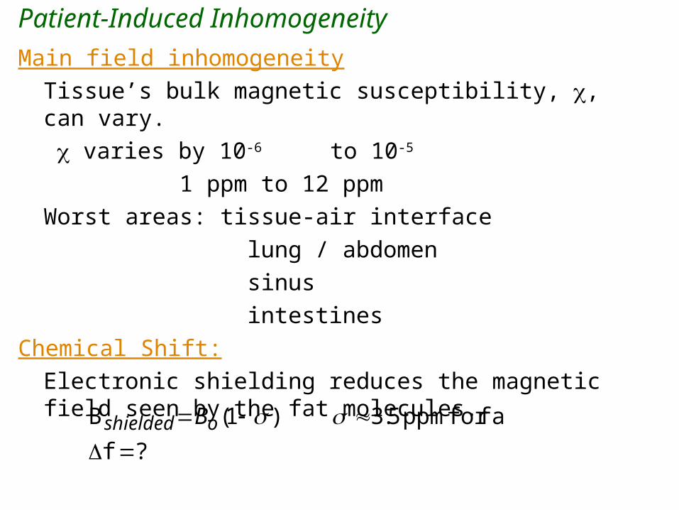
Patient-Induced Inhomogeneity
Main field inhomogeneity
Tissue’s bulk magnetic susceptibility, , can vary.
varies by 10-6 to 10-5
1 ppm to 12 ppm
Worst areas: tissue-air interface
lung / abdomen
sinus
intestines
Chemical Shift:
Electronic shielding reduces the magnetic field seen by the fat molecules.
?f
fatfor ppm 5.3 )1(B
oshielded B

Patient-Induced InhomogeneityT2*
z component of magnetic field
is the field inhomogeneity term.
)(EBo r
)(E r
dVeermts rTttr
volume
)(/)(iω 2E )()(
- unintended
- due to local
neighborhood
inhomogeneity
- T2 effect
T2*
Varying magnetic field in immediate neighborhood (within a voxel) causes in-plane spins to dephase earlier than intended T2 decay. The faster decay has a decay constant referred to as T2*

'22
*2
111
TTT
T2* Equation
• T2* is actual decay in gradient echo
experiment.• T2 is actual spin-spin decay of material. We
will see how to easily measure this today.• Last term is decay due to local magnetic
environment

Causes of Phase ErrorMain field inhomogeneity,
patient-induced inhomogeneity,
gradient non-linearity,
and blood flow
all cause phase errors (or frequency errors, depending on your point of view). That is, spins will resonate faster or slower than our basic formula predicts.
Chemical shift is another type of phase error.
Let’s study the effects of these phenomena on the two major classes of MR imaging sequences.
)B(γω o rG

Gradient EchoThis is what we have studied to date:
RF t
Gx
s(t)
90º
20
t
t
Where does the gradient echo form?
What happens when we push the echo time out?
drttzyx
dzyxtzyx
tcs
t
0E
0
)(Gγ),,(ω
),,,(ω),,,(
t

2D Fourier Transform (2)2D Fourier Transform: (2D FT or Spin Warp)
1)
t
Gx(t)
RF
6GRADECH.AVI

Susceptibility Artifacts
Short echo time
Longer echo time
Water /plastic interface
has large susceptibility.
Notice dropout of signal
around water discs in bottom image.
Note: Not exactly the same slice and so bottom slice has some water signal also around discs.

Perils of Gradient Echo Imaging and T2*
TE = 8 ms TE = 24 ms
0.17 T GE Orthopedic Scanner

Spin Echo Phenomenon

Spin Echo Generation
Image Copyright Nishimura
90º 180º
(a) (b) (c) (d) (e)
Spin Echo Generation: Following a 90º excitation pulse, (a -b) the spin vectors begin to fan out and dephase because of
precessional frequency differences (c) at time , a 180º excitation rotates all the spins about the x’ axis (d) The spin vectors continue to precess at their slightly different
frequencies, rephasing at time 2 (e).

Tip Bulk Magnetization
x'
y'
z'
M

Tip Bulk Magnetization
x'
y'
z'
M
B1

Tip Bulk Magnetization
x'
y'
z'
B1

Tip Bulk Magnetization
x'
y'
z'
B1

Tip Bulk Magnetization
x'
y'
z'
B1

Transverse Magnetization
x'
y'
z'
Mtrans

T2 Decay
x'
y'
z'
T2 relaxation is dephasing of transverse magnetization
f
s

T2 Decay
x'
y'
z'
T2 relaxation is dephasing of transverse magnetization
f
s

T2 Decay
x'
y'
z'
T2 relaxation is dephasing of transverse magnetization
f
s

Refocusing Pulse
x'
y'
z'
f
s
B1

Refocusing Pulse
x'
y'
z'
f
s
B1

Refocusing Pulse
x'
y'
z'
f
s
B1

Rephasing
x'
y'
z'
f
s

Rephasing
x'
y'
z'
f
s

Rephasing
x'
y'
z'
f
s

Echo Formation
x'
y'
z'
Mtrans

Spin Echoes
The phase errors E are for the most part out of our control, but there is a method around them called a spin echo.
Chemical shift, CS , can be compensated with techniques beyond the scope of this class. But these require more scan time also..
However, we can use a “spin echo” to correct for both effects. Spin echoes form the second major class of pulse sequences.
Spin echoes use a 90º pulse as we have seen, but also a second RF pulse, a 180º pulse. Let’s first consider just the effects of off-resonance and ignore the imaging gradients.
drttzyxdzyxtzyxt
cst
0E0)(Gγ),,(ω),,,(ω),,,(
RF t
90º
20
180º

Spin Echo Generation in Rotating Frame
The phase error just prior to the 180º pulse isJust after the 180º pulse, it is
Then we let the spins progress for another .
),,(ω)( E_ zyx
Image Copyright Nishimura
90º 180º
(a) (b) (c) (d) (e)
),,(
)()(
E
_
zyx
)2)(,,(),,,(
'),,,()()2(
EE
2E
zyxzyx
dttzyx
A “spin echo” is said to be formed at t=2

Effect of echo delay on signal lossEffect of echo delay on susceptibility-induced signal losses:
(a) TE = 15 ms
(b) TE = 10 ms
(c) TE = 5 ms Note artifactual signal reduction in the
region of the nasal and mastoid sinuses.
Notice homogeneity of water discs
and air bubble appearance.

Spin Echo Pulse Sequence
Z grad
RFX Grad
Y Grad Gy
90180
Echo Time (TE) = 2
TE
TR
90

Spin Echo Signal Plus X Readout Gradient
Left plot experiences no refocusing pulse. Right plot experiences
refocusing pulse half way through time series. Sum of magnitude of
spins given on top. Time series ends at echo time.
6SPINECH.AVI

Spin Echo RF Sequence
T2
T2*
TE
TR
T2*
1 =T2
1 + B0

Spin Echo Sequence with 180 y pulse

Spin Echo Sequence – Long Versus Short T2
long T2 short T2
long T2
short T2
T2-weighting: long TE, long TRPD-weighting: short TE, long TR

T1, T2, and Density-Weighted Images
T1-weighted T2-weighted -weighted

Scan Duration
Scan Time = TR PE NEX
TR = repetition timePE = number of phase encoding valuesNEX = number of excitations (averages)

Spin Echo Formation• For spins to be refocused, they must
experience the same magnetic field after the 180 refocusing pulse as they experienced before the 180 refocusing pulse.
• Thus, only dephasing due to macroscopic inhomogeneities (B0) is refocused. Dephasing due to microscopic inhomogenieties (T2) is not refocused.

Spin Echo Parameters
TR TE
T1-weighting short (400 msec) short (20 msec)
T2-weighting long (3000 msec) long (100 msec)
-weighting long (3000 msec) short (20 msec)

Signal vs Weighting
T1-weighting long T1, small signal short T1, large signal
T2-weighting long T2, large signal short T2, small signal
-weighting high , large signal low , small signal
T1-weighted T2-weighted -weighted

Images of the Knee
-weighted T2-weightedNeeds longer TE

T2 & T2* Relaxation: Image Contrast Sources
Mxy
Time
T2*
T2
T2*
1 =T2
1 + B0

FSE Pulse Sequence Timing Diagram
SliceSelect
PhaseEncode
Freq.Encode
rf
Signal
90° 180° 180° 180° 180°
ESP
ETL=4

PhaseDirection
Frequency Direction
Filling k-space FSE

Scan Duration
Scan Time = TR PE/ETL NEX
TR = repetition timePE = number of phase encoding valuesNEX = number of excitations (averages)ETL = echo train length

T2 Weighting (Various Sequences)
FSE SE
TR = 2500TE = 116ETL = 16NEX = 224 slices17 slices/pass2 passesTime = 2:51
TR = 2500TE = 112
ETL = N/ANEX = 124 slices
20 slices/pass2 passes
Time = 22:21

Inversion Recovery RF Sequence

Inversion Recovery (IR) Sequence & Spin Behavior

Inversion Recovery
SliceSelectPhaseEncode
Freq.Encode
rf
Signal
90° 180°180°
TI

IR Sequence – Short Versus Long T1

Inversion Recovery Signal
longer T1
short T1
Mlong
TI
Short T1 = brighter
Long T1 = darker
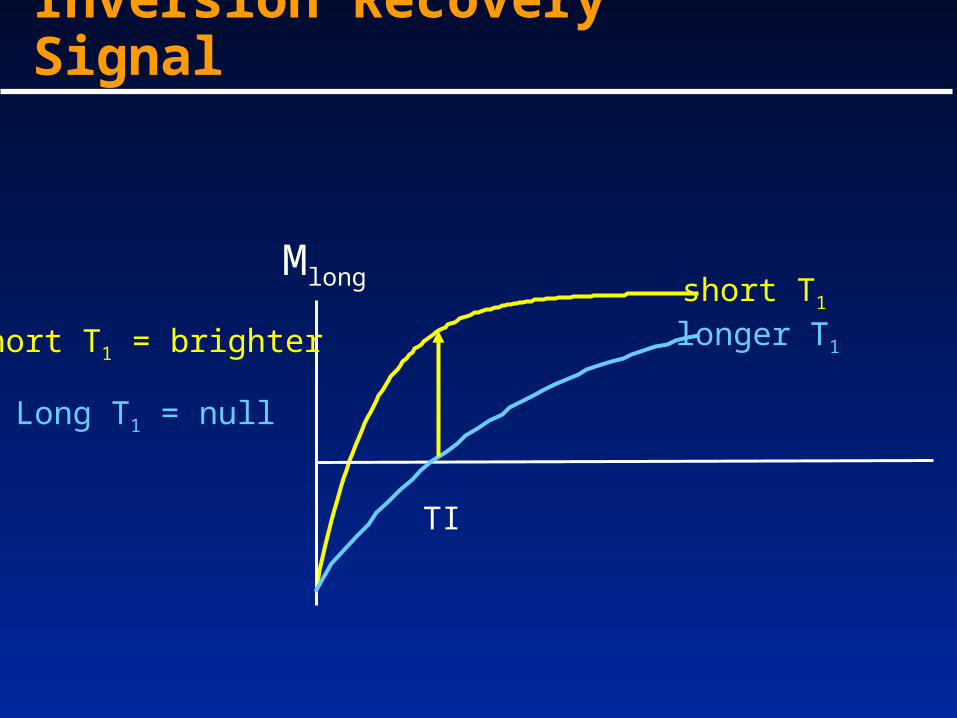
Inversion Recovery Signal
longer T1
short T1
Mlong
TI
Short T1 = brighter
Long T1 = null

Short Tau Inversion Recovery (Fat Nulled)
longer T1
short T1 (fat)Mlong
TI
Short T1 = null
Long T1 = brighter
STIR

Spine: T1 versus T2 versus STIR
T1 T2 STIR

Inversion Recovery II
Coronal Tumor
Here the inversion recovery delay is very long ( ~2 s). Here the idea
is to null CSF so one can distinguish tumor from CSF. Notice tumor
still has positive contrast.
IR pulse precedes
T2-weighted sequence

MR: SNR vs Field Strength
Signal
oo BM
ooreceive Bt
Ms
- energy separation of Zeeman levels
Signal amplitude is 2oB
Noise Power
Receiver oB
Patient 2oB
- electronics
- patient electrons in Brownian motion
Patient noise dominates at most field strengths T) 1.( oB
o
o
o BB
BSNR
2
2
- Faraday’s Law of Induction

SNR
• We will first consider the case where we ignore T1 and T2 of the tissue involved. – leave sequence dependent effects for later
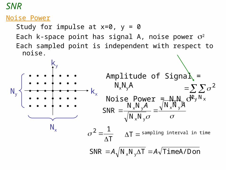
SNRNoise Power
Study for impulse at x=0, y = 0
Each k-space point has signal A, noise power 2
Each sampled point is independent with respect to noise.
kx
ky
Ny
Nxsampling interval in time
y xN N
2
AA yx
yx
yxNN
NN
NNSNR
T
12
T
Amplitude of Signal = NxNyA
Noise Power = NxNy 2
on A/D TimeTNNSNR yx AA

SNR
voxel size since this determines the # of protons per voxelReplace A above by voxel size
SNR
Together,
on A/D TimeTNNSNR yx AA
on A/D Timesize voxelSNR
SNR
Time Resolution

Scan Time
Image b) has twice the SNR as a)
at an expense of four times the scan time

Axial Forearm T2-Weighted
TE = 15 ms TE = 45 ms TE = 75 ms
TE = 105 ms
TR = 4000 ms for all
Notice appearance of supinator
Muscle ( arrow) on all images.
One arm had an exercise protocol.
Which one? What is in between arms?

TR
1,nzM
zMnzM ,
During each TR, Mz will recover.
When in steady-state,
nznz MM ,1,
Where n-1 is the n-1th RF pulse
and n is the nth RF pulse.
)1(
/2,
)sin()cos1(
)1(
)cos1(
)1(
)1()cos1(
)1(cos
condition statesteady- Use
)1(cos
for in Plug
)1(
equationrecovery
cos
cosby reduced is , ingAfter tipp
condition stateSteady
1/0
1/0
1/0
,
1/0,
1/0
1/,,
1/0
1/1,,
,
1/0
1/,,
1,,
,1,
TTR
TTR
TTR
nz
TTRnz
TTRTTRnznz
TTRTTRnznz
nz
TTRTTRnznz
nznz
nznz
eMMxy
For
eMMxy
eMM
eMM
eMeMM
eMeMM
M
eMeMM
Mz
MM
Mz
MM