
Waiatarua Spring Clean. WAIATARUA QUIZ NIGHT Qigong Class ...

K. A. Connor, 1 Revised: 11 April 2016
Rensselaer Polytechnic Institute Troy, New York, USA
Quiz II Spring 2016
Draw circuit diagrams for all problems, especially as you simplify the circuits.
Be sure to fully annotate plots, even when the problem does not ask you to do this.
Show all of your work
Almost all problems can be solved using more than one method. Check your answers by
using a second method.
At least skim through the entire quiz before you begin and then start with the problems
you know best.
The proctor will only answer clarification questions where wording is unclear or where
there may be errors/typos. No other questions will be responded to.
Extra Task for Free Points: This semester is the second pilot version of this course, so I
am still trying some things to find out the best type of questions to ask in quizzes to
address the desired learning outcomes. Note that every step in each question has a point
total assigned to it. For any part of a question that you find very challenging, circle the
point total. An example is shown below. Do this for up to 20 points worth of question
parts and you will receive 15 free points. If you find none of the questions challenging,
please indicate that at the bottom of this page and you will also receive the 15 points.
c. (4 Pts) What should we do to fix the presidential election process in the US?

K. A. Connor, 2 Revised: 11 April 2016
Rensselaer Polytechnic Institute Troy, New York, USA
Quiz II Spring 2016
Excerpts from Florida Job Postings Examples of what you should be looking at.
Lockheed-Martin: Experienced Electronics Engineer (Cape Canaveral) Perform electronics
engineering support of the completion of development activities and support of production for
three Fleet Ballistic Missile D5 Life Extension Avionics packages.
Basic Qualifications 1. Degree emphasis in Electrical, Electronics, or Computer Engineering from an accredited
college or equivalent professional experience combined with experience and specialized training
commensurate with the position. 2. Familiarity with Electrical Engineering Simulation Tools
(such as SPICE). Experience using lab equipment (oscilloscopes, logic analyzers, power
supplies). 3. .Excellent communication skills with the ability to articulate complex technical
issues to subordinates, peers, management, subcontractors and customers. 4. .Experience
working in team environments and must model excellent interpersonal, communication and
organizational skills. 5. .Must be willing to travel 1-2 times per month.
Desired skills 1..Automated test management software (such as Test Stand, Test Studio or Matlab)
2..Experience in the development of analog, digital and/or mixed signal circuit design for
missile, spacecraft or aircraft avionics electronics 3.Mentor DxSim or Hyperlynx 4.C
programming language proficiency 5.Experience as CPE or CPE delegate on avionics electronics
package or component design 6.Experience in providing engineering support to electronics
package production and the disposition of production hardware (E.g., Material Review Board or
equivalent) and a long list of experiences not relevant to this course.
FARO: FPGA Electronics Engineer (Lake Mary) Focus on FPGA code development for
image and video processing. In addition, the engineer will help design and develop circuit boards
relating to the FPGA development, as well as troubleshooting boards to determine root cause of
circuit and board failures.
HIRING PREFERENCES:
Bachelor’s degree in Computer Engineering or Electrical Engineering
5+ years hands-on FPGA-based image processing development
Experience with both Verilog and VHDL
Experience creating image processing modules with MATLAB/Simulink
Experience with Altera, Xilinx, and Modelsim development tools
Outstanding debug/troubleshoot skills with Oscilloscope, Logic Analyzer, and on-chip
analyzers such as Altera SignalTap or Xilinx ChipScope
Embedded Microcontroller/Microprocessor/DSP and mixed signal circuit design
experience
Schematic capture tool experience: Cadence Allegro/OrCAD schematic capture preferred
PCB Layout tool experience: Cadence PCB Editor layout preferred
Embedded C/C++ desired
K. A. Connor, 3 Revised: 11 April 2016
Rensselaer Polytechnic Institute Troy, New York, USA
Quiz II Spring 2016
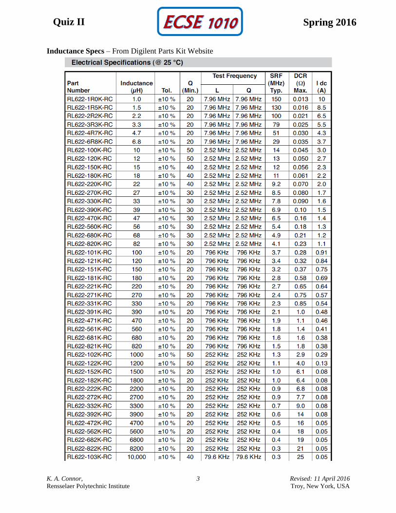
Inductance Specs – From Digilent Parts Kit Website
K. A. Connor, 4 Revised: 11 April 2016
Rensselaer Polytechnic Institute Troy, New York, USA
Quiz II Spring 2016
K. A. Connor, 5 Revised: 11 April 2016
Rensselaer Polytechnic Institute Troy, New York, USA
Quiz II Spring 2016
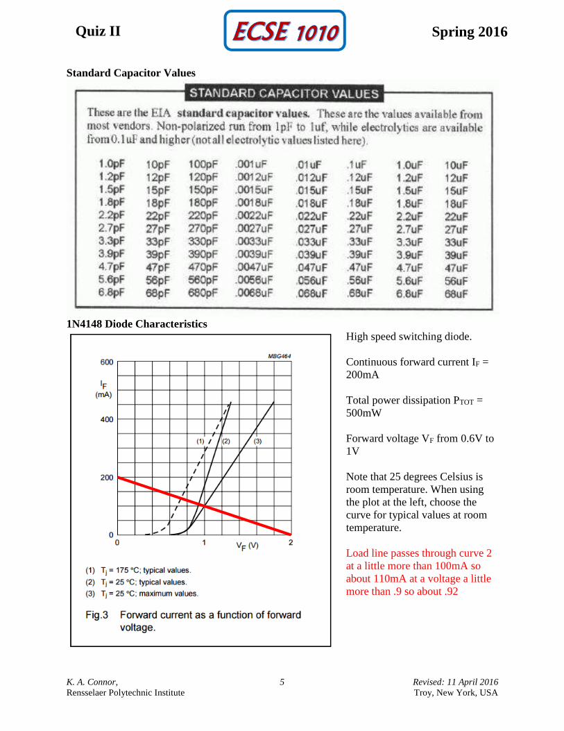
Standard Capacitor Values
1N4148 Diode Characteristics
High speed switching diode.
Continuous forward current IF =
200mA
Total power dissipation PTOT =
500mW
Forward voltage VF from 0.6V to
1V
Note that 25 degrees Celsius is
room temperature. When using
the plot at the left, choose the
curve for typical values at room
temperature.
Load line passes through curve 2
at a little more than 100mA so
about 110mA at a voltage a little
more than .9 so about .92
K. A. Connor, 6 Revised: 11 April 2016
Rensselaer Polytechnic Institute Troy, New York, USA
Quiz II Spring 2016
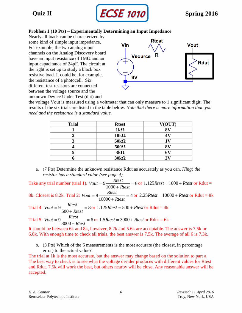
Problem 1 (10 Pts) – Experimentally Determining an Input Impedance Nearly all loads can be characterized by
some kind of simple input impedance.
For example, the two analog input
channels on the Analog Discovery board
have an input resistance of 1MΩ and an
input capacitance of 24pF. The circuit at
the right is set up to study a black box
resistive load. It could be, for example,
the resistance of a photocell. Six
different test resistors are connected
between the voltage source and the
unknown Device Under Test (dut) and
the voltage Vout is measured using a voltmeter that can only measure to 1 significant digit. The
results of the six trials are listed in the table below. Note that there is more information than you
need and the resistance is a standard value.
Trial Rtest V(OUT)
1 1kΩ 8V
2 10kΩ 4V
3 50kΩ 1V
4 500Ω 8V
5 3kΩ 6V
6 30kΩ 2V
a. (7 Pts) Determine the unknown resistance Rdut as accurately as you can. Hing: the
resistor has a standard value (see page 4).
Take any trial number (trial 1). 81000
9
Rtest
RtestVout or RtestRtest 1000125.1 or Rdut =
8k. Closest is 8.2k. Trial 2: 410000
9
Rtest
RtestVout or RtestRtest 1000025.2 or Rdut = 8k
Trial 4: 8500
9
Rtest
RtestVout or RtestRtest 500125.1 or Rdut = 4k
Trial 5: 63000
9
Rtest
RtestVout or RtestRtest 30005.1 or Rdut = 6k
It should be between 6k and 8k, however, 8.2k and 5.6k are acceptable. The answer is 7.5k or
6.8k. With enough time to check all trials, the best answer is 7.5k. The average of all 6 is 7.3k.
b. (3 Pts) Which of the 6 measurements is the most accurate (the closest, in percentage
error) to the actual value?
The trial at 1k is the most accurate, but the answer may change based on the solution to part a.
The best way to check is to see what the voltage divider produces with different values for Rtest
and Rdut. 7.5k will work the best, but others nearby will be close. Any reasonable answer will be
accepted.
K. A. Connor, 7 Revised: 11 April 2016
Rensselaer Polytechnic Institute Troy, New York, USA
Quiz II Spring 2016
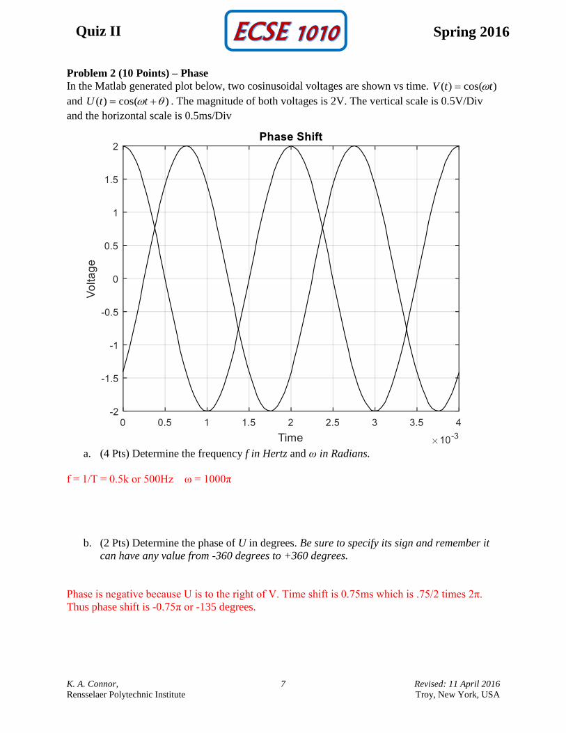
Problem 2 (10 Points) – Phase
In the Matlab generated plot below, two cosinusoidal voltages are shown vs time. )cos()( ttV
and )cos()( ttU . The magnitude of both voltages is 2V. The vertical scale is 0.5V/Div
and the horizontal scale is 0.5ms/Div
a. (4 Pts) Determine the frequency f in Hertz and ω in Radians.
f = 1/T = 0.5k or 500Hz ω = 1000π
b. (2 Pts) Determine the phase of U in degrees. Be sure to specify its sign and remember it
can have any value from -360 degrees to +360 degrees.
Phase is negative because U is to the right of V. Time shift is 0.75ms which is .75/2 times 2π.
Thus phase shift is -0.75π or -135 degrees.
K. A. Connor, 8 Revised: 11 April 2016
Rensselaer Polytechnic Institute Troy, New York, USA
Quiz II Spring 2016
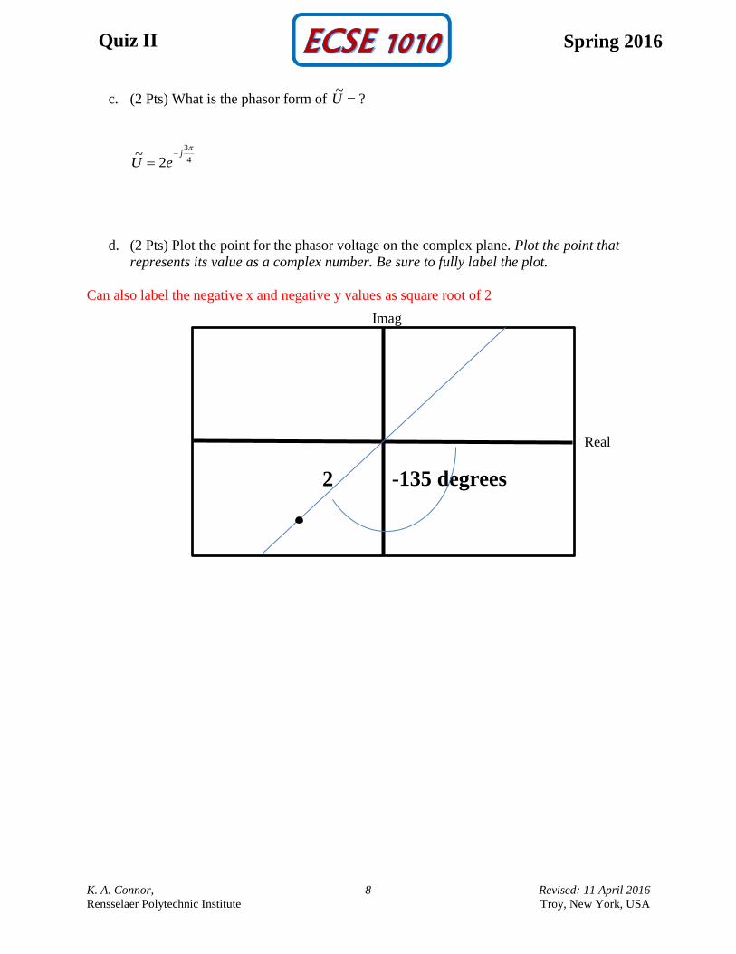
c. (2 Pts) What is the phasor form of ?~U
4
3
2~
j
eU
d. (2 Pts) Plot the point for the phasor voltage on the complex plane. Plot the point that
represents its value as a complex number. Be sure to fully label the plot.
Can also label the negative x and negative y values as square root of 2
Real
Imag
2 -135 degrees
K. A. Connor, 9 Revised: 11 April 2016
Rensselaer Polytechnic Institute Troy, New York, USA
Quiz II Spring 2016
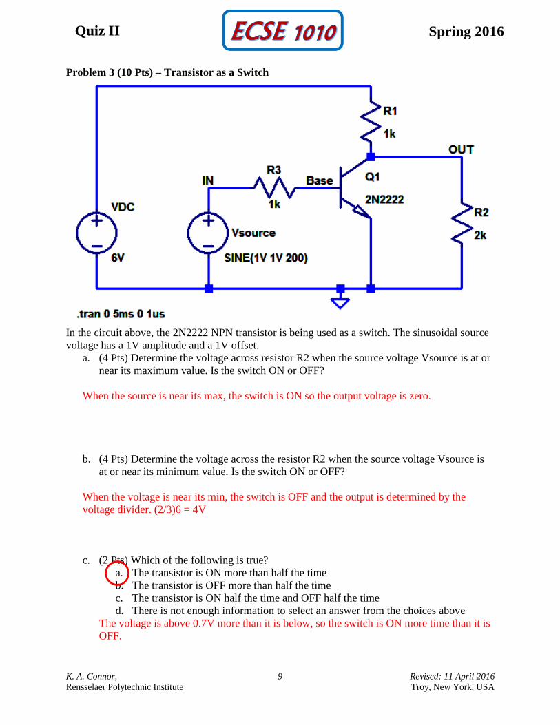
Problem 3 (10 Pts) – Transistor as a Switch
In the circuit above, the 2N2222 NPN transistor is being used as a switch. The sinusoidal source
voltage has a 1V amplitude and a 1V offset.
a. (4 Pts) Determine the voltage across resistor R2 when the source voltage Vsource is at or
near its maximum value. Is the switch ON or OFF?
When the source is near its max, the switch is ON so the output voltage is zero.
b. (4 Pts) Determine the voltage across the resistor R2 when the source voltage Vsource is
at or near its minimum value. Is the switch ON or OFF?
When the voltage is near its min, the switch is OFF and the output is determined by the
voltage divider. (2/3)6 = 4V
c. (2 Pts) Which of the following is true?
a. The transistor is ON more than half the time
b. The transistor is OFF more than half the time
c. The transistor is ON half the time and OFF half the time
d. There is not enough information to select an answer from the choices above
The voltage is above 0.7V more than it is below, so the switch is ON more time than it is
OFF.
K. A. Connor, 10 Revised: 11 April 2016
Rensselaer Polytechnic Institute Troy, New York, USA
Quiz II Spring 2016
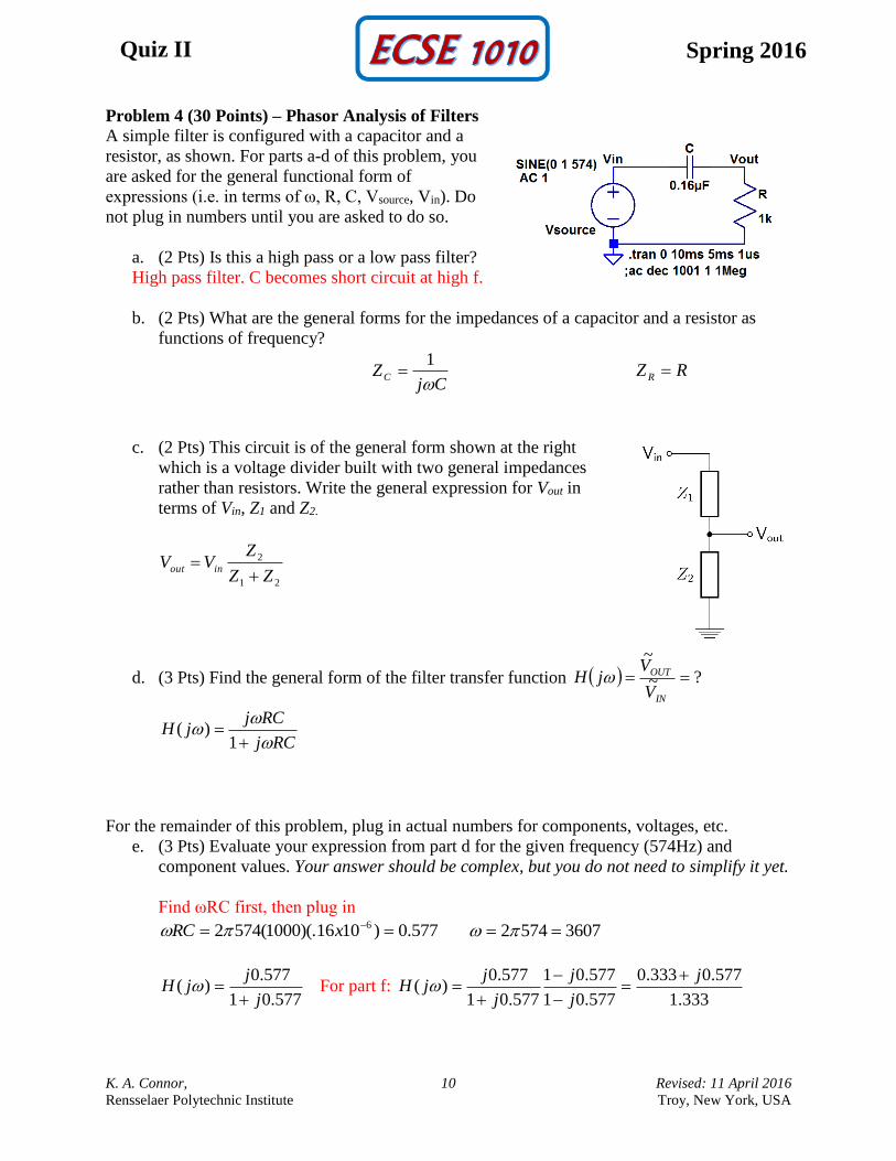
Problem 4 (30 Points) – Phasor Analysis of Filters
A simple filter is configured with a capacitor and a
resistor, as shown. For parts a-d of this problem, you
are asked for the general functional form of
expressions (i.e. in terms of ω, R, C, Vsource, Vin). Do
not plug in numbers until you are asked to do so.
a. (2 Pts) Is this a high pass or a low pass filter?
High pass filter. C becomes short circuit at high f.
b. (2 Pts) What are the general forms for the impedances of a capacitor and a resistor as
functions of frequency?
CjZC
1 RZ R
c. (2 Pts) This circuit is of the general form shown at the right
which is a voltage divider built with two general impedances
rather than resistors. Write the general expression for Vout in
terms of Vin, Z1 and Z2.
21
2
ZZ
ZVV inout
d. (3 Pts) Find the general form of the filter transfer function ?~
~
IN
OUT
V
VjH
RCj
RCjjH
1)(
For the remainder of this problem, plug in actual numbers for components, voltages, etc.
e. (3 Pts) Evaluate your expression from part d for the given frequency (574Hz) and
component values. Your answer should be complex, but you do not need to simplify it yet.
Find ωRC first, then plug in
577.0)1016)(.1000(5742 6 xRC 36075742
577.01
577.0)(
j
jjH
For part f:
333.1
577.0333.0
577.01
577.01
577.01
577.0)(
j
j
j
j
jjH
K. A. Connor, 11 Revised: 11 April 2016
Rensselaer Polytechnic Institute Troy, New York, USA
Quiz II Spring 2016
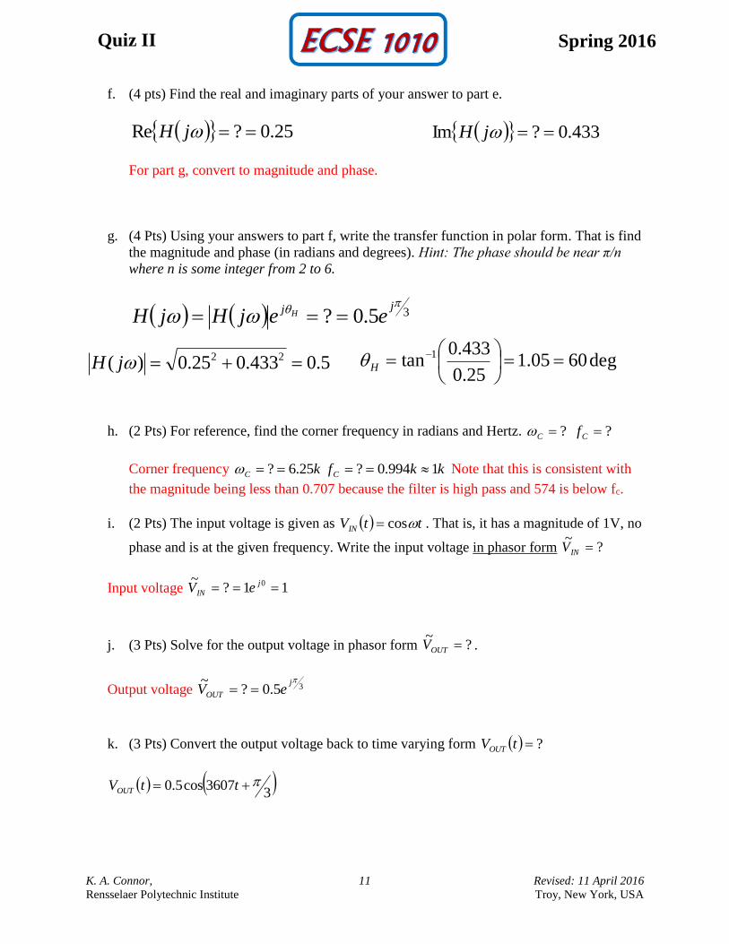
f. (4 pts) Find the real and imaginary parts of your answer to part e.
25.0?Re jH 433.0?Im jH
For part g, convert to magnitude and phase.
g. (4 Pts) Using your answers to part f, write the transfer function in polar form. That is find
the magnitude and phase (in radians and degrees). Hint: The phase should be near π/n
where n is some integer from 2 to 6.
35.0?
jj
eejHjH H
5.0433.025.0)( 22 jH deg6005.125.0
433.0tan 1
H
h. (2 Pts) For reference, find the corner frequency in radians and Hertz. ?C ?Cf
Corner frequency kC 25.6? kkfC 1994.0? Note that this is consistent with
the magnitude being less than 0.707 because the filter is high pass and 574 is below fc.
i. (2 Pts) The input voltage is given as ttVIN cos . That is, it has a magnitude of 1V, no
phase and is at the given frequency. Write the input voltage in phasor form ?~
INV
Input voltage 11?~ 0 j
IN eV
j. (3 Pts) Solve for the output voltage in phasor form ?~
OUTV .
Output voltage 35.0?~ j
OUT eV
k. (3 Pts) Convert the output voltage back to time varying form ?tVOUT
3
3607cos5.0 ttVOUT
K. A. Connor, 12 Revised: 11 April 2016
Rensselaer Polytechnic Institute Troy, New York, USA
Quiz II Spring 2016
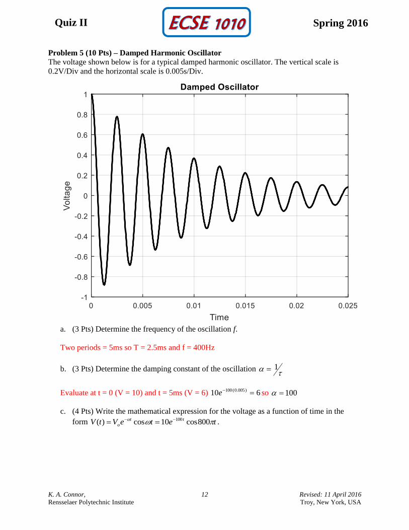
Problem 5 (10 Pts) – Damped Harmonic Oscillator
The voltage shown below is for a typical damped harmonic oscillator. The vertical scale is
0.2V/Div and the horizontal scale is 0.005s/Div.
a. (3 Pts) Determine the frequency of the oscillation f.
Two periods = 5ms so T = 2.5ms and f = 400Hz
b. (3 Pts) Determine the damping constant of the oscillation
1
Evaluate at t = 0 (V = 10) and t = 5ms (V = 6) 610 )005.0(100 e so 100
c. (4 Pts) Write the mathematical expression for the voltage as a function of time in the
form teteVtV tt
o 800cos10cos)( 100 .
K. A. Connor, 13 Revised: 11 April 2016
Rensselaer Polytechnic Institute Troy, New York, USA
Quiz II Spring 2016
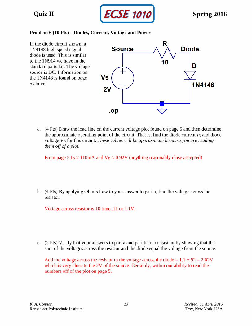
Problem 6 (10 Pts) – Diodes, Current, Voltage and Power
In the diode circuit shown, a
1N4148 high speed signal
diode is used. This is similar
to the 1N914 we have in the
standard parts kit. The voltage
source is DC. Information on
the 1N4148 is found on page
5 above.
a. (4 Pts) Draw the load line on the current voltage plot found on page 5 and then determine
the approximate operating point of the circuit. That is, find the diode current ID and diode
voltage VD for this circuit. These values will be approximate because you are reading
them off of a plot.
From page 5 ID ≈ 110mA and VD ≈ 0.92V (anything reasonably close accepted)
b. (4 Pts) By applying Ohm’s Law to your answer to part a, find the voltage across the
resistor.
Voltage across resistor is 10 time .11 or 1.1V.
c. (2 Pts) Verify that your answers to part a and part b are consistent by showing that the
sum of the voltages across the resistor and the diode equal the voltage from the source.
Add the voltage across the resistor to the voltage across the diode = 1.1 +.92 = 2.02V
which is very close to the 2V of the source. Certainly, within our ability to read the
numbers off of the plot on page 5.


![Spring fall hub quiz [Set-2]](https://static.fdocuments.us/doc/165x107/5888c15c1a28ab200f8b560f/spring-fall-hub-quiz-set-2.jpg)


