Quickstart Type 8681 Control Head
76
Quickstart English Deutsch Français Type 8681 Control Head Steuerkopf Tête de commande
Transcript of Quickstart Type 8681 Control Head

Quickstart
English Deutsch Français
Type 8681Control Head
Steuerkopf
Tête de commande

We reserve the right to make technical changes without notice.Technische Änderungen vorbehalten.Sous réserve de modifications techniques.
© Bürkert Werke GmbH, 2010 - 2014
Operating Instructions 1412/04_EU-ML_00810362 / Original DE

3
Type 8681
1. THEQUICKSTART..........................................................................................51.1. Definition of term “Device“ ............................................................ 51.2. Symbols .............................................................................................. 5
2. AUTHORIZEDUSE.........................................................................................62.1. Restrictions ........................................................................................ 6
3. BASICSAFETYINSTRUCTIONS.............................................................6
4. GENERALINFORMATION...........................................................................84.1. Contact address ............................................................................... 84.2. Warranty ............................................................................................. 84.3. Information on the Internet ............................................................. 8
5. STRUCTUREANDFUNCTION..................................................................85.1. Manual Control ................................................................................. 85.2. Structure ............................................................................................ 9
6. TECHNICALDATA...........................................................................................96.1. Conformity ........................................................................................ 96.2. Standards ........................................................................................... 96.3. Operating Conditions ...................................................................... 96.4. Mechanical Data .............................................................................106.5. Pneumatic Data ..............................................................................106.6. Position Measuring System Data................................................106.7. Electrical Data .................................................................................10
7. ASSEMBLY/INSTALLATION................................................................... 117.1. Safety instructions .........................................................................11
7.2. Assembly ..........................................................................................117.3. Pneumatic Installation ...................................................................117.4. Opening and Closing the Housing ............................................127.5. Electrical Installation ......................................................................12
8. 24VDC-DESIGN....................................................................................... 138.1. Connection options .......................................................................138.2. Electrical Data .................................................................................138.3. Electrical Installation (24 V DC) ..........................................14
9. AS-I-DESIGN............................................................................................... 169.1. Connection options .......................................................................169.2. Maximum Length of the Bus Line ...............................................169.3. Number of Connectable Control Heads ...................................169.4. Electrical Data .................................................................................169.5. Electrical installation AS Interface ..............................................17
10. DEVICENET-DESIGN..............................................................................1810.1. Connection ....................................................................................1810.2. DeviceNet Specification .............................................................1810.3. Length of the Bus line .................................................................1810.4. Electrical Data ...............................................................................1910.5. Electrical Installation (DVN) .......................................................1910.6. Network Topology ........................................................................2010.7. Configuring the Baud rate and DVN address .......................2010.8. Configuration of Process Data .................................................2010.9. Configuration of the Safety Position of Solenoid Valves if Bus Error .....................................................................................21
TabelofContents
english
4
Type 8681
11. 120VAC-DESIGN..................................................................................2211.1. Connection ....................................................................................2211.2. Electrical Data ...............................................................................2211.3. Electrical Installation ....................................................................23
12. POSITIONMEASURINGSYSTEM.....................................................2412.1. Teach-In ..........................................................................................2412.2. Teach-Reset ..................................................................................2512.3. Autotune .........................................................................................2512.4. LED - Color Assignments ..........................................................25
13. START-UP......................................................................................................25
14. PACKAGING,TRANSPORT,STORAGE,DISPOSAL................ 26
english

5
TheQuickstart
Type 8681
1. THEQUICKSTARTKeep these instructions in a location which is easily accessible to every user and make these instructions available to every new owner of the device.
Importantsafetyinformation!
Read Quickstart carefully and thoroughly. Study in particular the chapters entitled “2. Authorized use” and “3. Basic Safety Instructions”.• Quickstart must be read and understood.
Quickstart explains, for example, how to install and start-up the device. A detailed description of the device can be found in the operating instructions for the Type 8681.
The operating instructions can be found on the Internet at: www.burkert.com
> Documentation > Manuals / Approvals > Search by Type
1.1. Definitionofterm“Device“The term “device” used in these instructions always stands for the positioner Type 8681.
1.2. SymbolsThe following symbols are used in these instructions.
DANGER!
Warnsofanimmediatedanger!• Failure to observe the warning may result in a fatal or serious injury.
WARNING!
Warnsofapotentiallydangeroussituation!• Failure to observe the warning may result in serious injuries or death.
CAUTION!
Warnsofapossibledanger!• Failure to observe this warning may result in a moderate or minor
injury.
NOTE!
Warnsofdamagetoproperty!
Important tips and recommendations for safe and flawless functioning of the device.
Refers to information in these operating instructions or in other documentation.
→ Designates a procedure which you must carry out.
english

6
Authorizeduse
Type 8681
2. AUTHORIZEDUSE
Non-authorizeduseoftheControlHeadType8681maybeahazardtopeople,nearbyequipmentandtheenvironment.• The Control Head has been designed for use as actuation of
pneumatically operated process valves and / or for recording the switching states of these.
• Use according to the authorized data, operating conditions and conditions of use specified in the contract documents and ope-rating instructions.
• In view of the large number of options for use it might be necessary to test prior to installation whether the control head is suitable for the concrete use. If you have any questions, please contact your Bürkert Service Center.
• The device may be used only in conjunction with third-party devices and components recommended and authorized by Burkert.
• Any unauthorized reconstructions and changes to the control head are prohibited for safety reasons.
• Correct transportation, correct storage and installation and care-ful use and maintenance are essential for reliable and faultless operation.
• For connecting the control head, use line installations that do not cause any mechanical stresses.
• Use the device only as intended.
2.1. RestrictionsIf exporting the system/device, observe any existing restrictions.
3. BASICSAFETYINSTRUCTIONSThese safety instructions do not make allowance for any
• contingencies and events which may arise during the installation, operation and maintenance of the devices.
• local safety regulations - the operator is responsible for observing these regulations, also with reference to the installation personnel.
DANGER!
Danger–highpressure!Before loosening pneumatic lines and valves, turn off the pressure and vent the lines.
Dangerofexplosioninexplosiveatmosphere(onlyintheeventofafaultasitiszone2)!• Opening the hood or the housing in an explosive atmosphere is
only allowed in a not energized state!• It should be secured against opening without tools using a seal!
• Activating the DIP switches on the circuit board, using the service interface and the Teach buttons is not allowed in explosive atmosphere!
• Layers of dust on the housing may not exceed 5 mm! Lint, con-ductive and non-conductive dust particles are allowed. The inside of the housing may not be dirty!
• When wiping the control head, use a damp or anti-static cloth in the explosion-risk area to prevent electrostatic charges!
english

7
BasicSafetyInstructions
Type 8681
WARNING!
Riskofelectricshock!• Before reaching into the system (except for the Teach-In procedure
in a non-explosive atmosphere) switch off the power supply and secure it to prevent restarting!
• Observe applicable accident prevention and safety regulations for electrical equipment!
GeneralHazardousSituations
To prevent injuries, ensure that:• the system cannot be activated unintentionally.• installation and maintenance work, as well as operator control
actions may be carried out by authorized, qualified technicians only and with the appropriate tools.
• not any unauthorized internal or external modifications are made to the device.
• after an interruption in the power supply or pneumatic supply, ensure that the process is restarted in a defined or controlled manner.
• the device may be installed and operated only when in perfect con-dition and in consideration of the operating instructions.
• the general rules of technology apply to application planning and operation of the device.
NOTE!
Electrostaticsensitivecomponents/modules!
• The device contains electronic components, which react sensitively to electrostatic discharge (ESD). Contact with electrostatically charged persons or objects may be hazardous to these
components. In the worst case scenario, they will be destroyed immediately or will fail after start-up
• Observe the requirements in accordance with DIN EN 61340-5-1 to minimize or avoid the possibility of damage caused by sudden electrostatic discharge!
• Also, ensure that you do not touch electronic components when the power supply voltage is present!
NOTE!
Warnsofdamagetoproperty!
• Don’t supply the medium connectors of the system with any liquids or with aggressive or flammable media.
• Don’t physically stress the housing (e.g. by placing heavy objects on it or standing on it).
• Don’t make any unauthorized external modifications to the device housings. Don’t paint the housing parts or screws.
• Only use compatible cleaning agents for cleaning the securely closed control head and always rinse thoroughly with clean water.
Control Head Type 8681 was developed with due conside-ration given to accepted safety rules and is state-of-the-art. Nevertheless, dangerous situations may occur.
english

8
GeneralInformation
Type 8681
4. GENERALINFORMATION
4.1. ContactaddressGermany
Bürkert Fluid Control Systems Sales Center Christian-Bürkert-Str. 13-17 D-74653 Ingelfingen Tel. + 49 (0) 7940 - 10 91 111 Fax + 49 (0) 7940 - 10 91 448 E-mail: [email protected]
International
Further contact addresses can be found on the Internet at:
www.burkert.com
4.2. WarrantyThe warranty is only valid if the Control Head Type 8681 is used as intended in accordance with the specified application conditions.
4.3. InformationontheInternetOperating instructions and data sheets on Type 8681 can be found on the Internet at:
www.burkert.com
> Documentation > Manuals / Approvals > Search by Type
5. STRUCTUREANDFUNCTIONThe Control Head Type 8681 has been designed for use as actuation of pneumatically operated process valves and/ or for recording the switching states of these.
For the recording and feedback of the process valve switching posi-tions to a higher-level control, the control head has been equipped with a contactless position measuring system, which works with three discrete, adjustable feedback signals (Teach-In Function).
Various pneumatic and electrical connection variants are available.
Positions and status information can be indicated by means of three signal colors.
5.1. ManualControlStandardly, the control head provides the following:
• a magnetic manual control that is easily accessible from the outside on the basis of encoded magnetic fields for Solenoid Valve 1 (Con-nection 2/A1), as well as
• a mechanical manual control accessible when the hood is open on each equipped solenoid valve.
english

9
TechnicalData
Type 8681
5.2. Structure
Pneumatic connections
Locking (shoulder) screws (2 x M5) - no sealing function, merely as protection against pulling off from the hub flange
Electrical connections (Cable glands)
Sealing lug
Electronics module (with service interface, connection terminals, DIP, Teach-In-buttons)
Position measuring system with LED’s
Flow restriction screw(s) of solenoid valves
Mechanical manual control at solenoid valves (red levers)
Fig. 1: Structure
6. TECHNICALDATA
6.1. ConformityIn accordance with the EC Declaration of conformity, the type 8681 is compliant with the EC Directives.
6.2. StandardsThe applied standards, which verify conformity with the EC Directives, can be found on the EC-Type Examination Certificate and / or the EC Declaration of Conformity.
The specifications on the respective rating plate apply to the respective control head. The symbols on the rating plate indicate the applicable directives or approvals.
6.3. OperatingConditionsStandardversion:Ambienttemperature: -10 ... +55 °C
Protectionclass: IP65 / IP67 according to EN 60529 or IP69K according to IEC 40050-9
Versionforuseinexplosiveatmosphere,zone2: Ambienttemperature: +5 ... +55 °C
Protectionclass:IP64 according to EN 60529 and requirements to EN 60079-0: 2009
If the control head is used in explosive atmosphere (zone 2) it has to be installed in a protected installation position according to IEC / EN 60079-0.
english

10
TechnicalData
Type 8681
6.4. MechanicalDataDimensions: see data sheet
Housingmaterial: outside: PA, PC, PPO, VA inside: ABS, PA, PMMA
Sealingmaterial: outside: CR, EPDM inside: EPDM, FKM, NBR
6.5. PneumaticDataControlmedium: air, neutral gases, Quality classes in accordance with ISO 8573-1 (5 µm filter recommended)
Dust content: max. particle size 40 µm, (quality class 7) max. particle density 10 mg/m3
Water content: max. pressure dew point -20 °C or (quality class 3) min. 10 °C below the lowest operating temperature
Oil content: max. 25 mg/m3
(quality class X)
Temperaturerangeofcompressedair: -10 to +50 °C
Pressurerange: 2.5 to 8 bar
Airrateofsolenoidvalve: 110 IN/min (for de-/aeration, ventilation)
(110 IN/min - supplied state 200 IN/min - maximum typical flow-rate) (QNn value according to definition for pressure drop from 7 to 6 bar absolute at +20 °C)
Connections: intake and exhaust air connection G1/4 Working connections G1/8
6.6. PositionMeasuringSystemDataStrokerange: 0 ... 80 mm (measuring range) Resolution: ≤ 0.1 mm Totalfault: ± 0.5 mm - when using a target as mentioned in the manual
6.7. ElectricalDatasee chapter “8. 24 V DC - Design”,
“9. AS-i - Design”, “10. DeviceNet- Design” and “11. 120 V AC - Design”.
english
11
Assembly/Installation
Type 8681
7. ASSEMBLY/INSTALLATION
7.1. Safetyinstructions
DANGER!
Riskofinjuryfromhighpressureintheequipment!• Before loosening pneumatic lines and valves, turn off the pressure
and vent the lines.
Dangerofexplosioninexplosiveatmosphere(onlyintheeventofafaultasitiszone2)!• Opening the hood or the housing in an explosive atmosphere is
only allowed in a not energized state!
WARNING!
Riskofinjuryduetoelectricalshock!• Before reaching into the system (except for the Teach-In procedure
in a non-explosive atmosphere) switch off the power supply and secure it to prevent restarting!
• Observe applicable accident prevention and safety regulations for electrical equipment!
Riskofinjuryfromimproperinstallation!• Installation may be carried out by authorized technicians only and
with the appropriate tools!
Riskofinjuryfromunintentionalactivationofthesystemandanuncontrolledrestart!• Secure system from unintentional activation.• Following assembly, ensure a controlled restart.
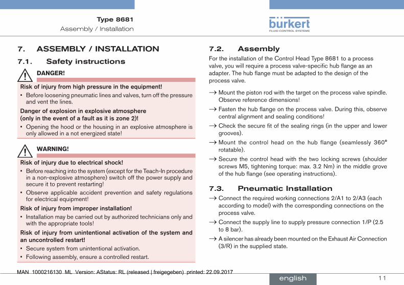
7.2. AssemblyFor the installation of the Control Head Type 8681 to a process valve, you will require a process valve-specific hub flange as an adapter. The hub flange must be adapted to the design of the process valve.
→ Mount the piston rod with the target on the process valve spindle. Observe reference dimensions!
→ Fasten the hub flange on the process valve. During this, observe central alignment and sealing conditions!
→ Check the secure fit of the sealing rings (in the upper and lower grooves).
→ Mount the control head on the hub flange (seamlessly 360° rotatable).
→ Secure the control head with the two locking screws (shoulder screws M5, tightening torque: max. 3.2 Nm) in the middle grove of the hub flange (see operating instructions).
7.3. PneumaticInstallation → Connect the required working connections 2/A1 to 2/A3 (each according to model) with the corresponding connections on the process valve.
→ Connect the supply line to supply pressure connection 1/P (2.5 to 8 bar).
→ A silencer has already been mounted on the Exhaust Air Connection (3/R) in the supplied state.
english
12
Assembly/Installation
Type 8681
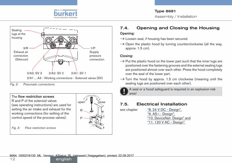
1/P Supply pressure connection
3/R Exhaust air connection
(Silencer)
2/A3: SV 3 2/A2: SV 2 2/A1: SV 1
2/A1 ... A3 - Working connections - Solenoid valves (SV)
Sealing lugs at the housing
Fig. 2: Pneumatic connections
The flowrestrictionscrews R and P of the solenoid valves (see operating instructions) are used for setting the air intake and exhaust for the working connections (for setting of the control speed of the process valves).
Fig. 3: Flow restriction screws
R P
open close
7.4. OpeningandClosingtheHousingOpening:
→ Loosen seal, if housing has been secured.
→ Open the plastic hood by turning counterclockwise (all the way, approx. 1.5 cm).
Closing:
→ Put the plastic hood on the lower part such that the inner lugs are positioned over the fastening grooves and the external sealing lugs are positioned almost over each other. Press the hood completely over the seal of the lower part.
→ Turn the hood by approx. 1.5 cm clockwise (meaning until the sealing lugs are positioned over each other).
A seal or a hood safeguard is required in an explosion-risk area!
7.5. ElectricalInstallationsee chapter “8. 24 V DC - Design”,
“9. AS-i - Design”, “10. DeviceNet- Design” and “11. 120 V AC - Design”.
english
13
24VDC-Design
Type 8681
8. 24VDC-DESIGN
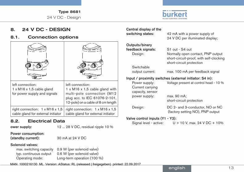
8.1. Connectionoptions
left connection: 1 x M16 x 1,5 cable gland for power supply and signals
left connection: 1 x M16 x 1,5 cable gland with multi-pole connection (M12 plug acc. to IEC 61076-2-101, 12-pole) on a cable of 8 cm length
right connection: 1 x M16 x 1,5 cable gland for external initiator
right connection: 1 x M16 x 1,5 cable gland for external initiator
8.2. ElectricalDataowersupply: 12 ... 28 V DC, residual ripple 10 %
Powerconsumption: (standbycurrent): 30 mA at 24 V DC
Solenoidvalves: max. switching capacity 0.9 W (per solenoid valve) typ. continuous output 0.6 W (per solenoid valve) Operating mode: Long-term operation (100 %)
Centraldisplayoftheswitchingstates: 42 mA with a power supply of
24 V DC per illuminated display;
Outputs/binaryfeedbacksignals: S1 out - S4 out Design: Normally open contact, PNP output
short-circuit-proof, with self-clocking short-circuit protection Switchable output current: max. 100 mA per feedback signal
Input/proximityswitches(externalinitiator:S4in): Power supply: Voltage present at control head - 10 %
Current carrying capacity, sensor power supply: max. 90 mA; short-circuit protection
Design: DC 2- and 3-conductor, NO or NC (factory setting NO), PNP output
Valvecontrolinputs(Y1-Y3): Signal level - active: U > 10 V, max. 24 V DC + 10%
english

14
24VDC-Design
Type 8681
8.3. ElectricalInstallation(24VDC)
DANGER!
Dangerofexplosioninexplosiveatmosphere(onlyintheeventofafaultasitiszone2)!• Opening the hood or the housing in an explosive atmosphere is
only allowed in a not energized state!
WARNING!
Riskofinjuryduetoelectricalshock!• Before reaching into the system (except for the Teach-In procedure
in a non-explosive atmosphere) switch off the power supply and secure it to prevent restarting!
• Observe applicable accident prevention and safety regulations for electrical equipment!
Riskofinjuryfromimproperinstallation!• Installation may be carried out by authorized technicians only and
with the appropriate tools!
Cableglands:
→ Open the housing.
→ Assemble connection cables for signals and power supply as well as for the external initiator.
→ Insert cables through the respective cable glands into the interior of the housing.
→ Secure the wires to the terminal strips according to the pin assign-ments depicted in “Fig. 4”
Solenoid valve connection with
status LED for SV1
Terminal
strip 1
Service interface
DIP switches for color coding the LED‘s
Terminal strip 2 (for external initiator)
Teach-In- buttons T1-3
SV-connections with status LED for SV2, 3
Fig. 4: Electronics module (24 V DC)
Terminalstrip1 Configuration
24 V Power supply 24 V
GND GND
S1 OUT Output position 1
S2 OUT Output position 2
S3 OUT Output position 3
S4 OUT Output external initiator
Y1 Input solenoid valve 1
Y2 Input solenoid valve 2
Y3 Input solenoid valve 3
english

15
24VDC-Design
Type 8681
Terminalstrip2 Configuration
24 V Power supply 24 V for external initiator
S4 IN Input external initiator
GND GND external initiator
→ Close the housing.
→ Ensure IP protection (dummy plugs)!
CableglandwithMulti-poleconnection:
Internal cabling work is not required for models with multi-pole con-nection. But you will require the correspondingly assembled cable sets with the following pin assignments:
Pin Description Configuration
1 24 V Power supply 24 V
2 GND GND
3 S1 OUT Output position 1
4 S2 OUT Output position 2
5 S3 OUT Output position 3
6 S4 OUT Output external initiator
7 Y1 Input solenoid valve 1
8 Y2 Input solenoid valve 2
9 Y3 Input solenoid valve 3
10-12 not used
An externalinitiator can be connected using the small 3-pin terminal strip 2 (see “Fig. 4” or manual, chapter „Connection of an external initiator“).
Input and output signals to the higher-level control (PLC):
Pin 9 - Y3
Pin 8 - Y2
12Pin 6 - S4 out
Pin 7 - Y1
Pin 1 - 24 V
Pin 5 - S3 out
Pin 4 - S2 out11
Pin 3 - S1 out Pin 2 - GND
10
Fig. 5: multi-pole connection 24 V DC (12-pole circular plug-in connector M12 x 1.0 - male, acc. to IEC 61076-2-101 — view onto the plug pins)
english

16
AS-i-Design
Type 8681
9. AS-I-DESIGN
9.1. Connectionoptions
left connection: 1 x M16 x 1,5 cable gland with Multi-poleconnection(M12 plug acc. to IEC 61076-2-101, 4-pole) on a cable of 8or80cm length
right connection: 1 x M16 x 1,5 cable gland for external initiator
9.2. MaximumLengthoftheBusLineThe bus cable may be a maximum of 100 m long. When designing the system, consider the length of the round cable leading directly to the control head (see example calculation in the operating instructions).
9.3. NumberofConnectableControlHeads
In AS interface versions with extended addressing range (A/B slave), 1 master can communicate with 62 slaves.
In AS interface versions with addressing range 31 slaves a maximum of 31 control heads can be connected to a bus line (the address range restriction).
9.4. ElectricalData
Powersupplyforthesolenoidvalves:
Standard:via AS-i 29,5 ... 31,6 V DC acc. specification; 21,0 ... 31,6 V DC acc. specific. Power24
Option:externally
(19,2 V DC to 31,6 V DC)
Setting the solenoid valve’s power supply using jumpers on the AS-interface electronics module.
Input/proximityswitches(externalinitiator:S4in): Power supply: AS interface voltage present at
control head - 10 % Current carrying capacity, sensor power supply: max. 30 mA; short-circuit protection
Design: DC 2- and 3-conductor, NO or NC (factory setting NO), PNP output
Inputs(from master 3 binary feedback signals and perspective): external initiator
Outputs(frommasterperspective)/Solenoidvalves: max. switching capacity 0.9 W (per solenoid valve) typ. continuous output 0.6 W (per solenoid valve) Pull-in current: 30 mA or 0.9 W / 200 ms Operating mode: Long-term operation (100 %)
english

17
AS-i-Design
Type 8681
Centraldisplayoftheswitchingstates: Power consumption: max. 33 mA or 1 W per illuminated display (at 30.5 V AS-i voltage)
PowersupplyviaASinterfacebus: Power consumption from max. 200 mA (incl. external AS interface: initiator with 30 mA)
Integrated short-circuit protection
ExternalPowerSupplyforthesolenoidvalves: Ext. power supply: 19.2 V DC to 31.6 V DC The power supply unit must include a secure disconnect in
accordance with IEC 364-4-41. It must conform to the SELV standard. The ground potential may not have an earth connection.
Max. power consumption from external power supply: ≤ 110 mA at 24 V DC
Integrated short-circuit protection
9.5. ElectricalinstallationASInterface
WARNING!
Dangerofexplosioninexplosiveatmosphere(zone2)!• See the note DANGER at chapter “8.3”, page 14!
Riskofinjuryduetoelectricalshock!• Before reaching into the system (except for the Teach-In proce-
dure in a non-explosive atmosphere) switch off the power supply and secure it to prevent restarting! Observe applicable accident prevention and safety regulations for electrical equipment!
Riskofinjuryfromimproperinstallation!• Installation may be carried out by authorized technicians only and
with the appropriate tools!
Internal cabling work is not required for any of the AS Interface designs with multi-pole connection. However, you will require the correspon-dingly assembled cable sets with the following pin assignments.
Pin 2
Pin 3 Pin 1
Pin 4
Fig. 6: Multi-pole connection AS-i
Likewise, the jumpers on the electronics module must be set corres-pondingly (power supply of the solenoid valves via AS-i or externally) - see page 16
Powersupplyofsolenoidvalves
Pin
(viaAS-i)Configuration
(externally)Configuration
Color
1 AS-i+ AS-i+ brown
2 not used GND white
3 AS-i- AS-i- blue
4 not used 24 V+ black
An externalinitiatorcan be connected using the small 3-pin terminal strip 2 - see manual, chapter „Connection of an external initiator“.
english

18
DeviceNet-Design
Type 8681
10. DEVICENET-DESIGN
10.1. Connection
left connection: 1 x M16 x 1,5 cable gland with Multi-poleconnection(M12 plug according to IEC 61076-2-101, 5-pole) on a cable of 80cm length
right connection: 1 x M16 x 1,5 cable gland for external initiator
10.2. DeviceNetSpecificationEDS file 8681.EDS
Icons 8681.ICO
Baud rate Factory setting: 125 kBit/s
Address Factory setting: 63
Process data 2 static input assemblies (Input: from the control head to the DeviceNet Master/Scanner) 1 static output assembly
Inputs 3 discrete feedback signals of the position measuring system (pos. S1 - S3), 1 discrete feedback signal of the external initiators (S4), 1 analog position signal in mm, Supply via DeviceNet string (11 to 25 V DC), Switch level high signal ≥ 5 V, Switch level low signal ≤ 1,5 V
Outputs 3 solenoid valves
Power consumption from the bus: max. 5 W, (3 valves with each 0,6 W)
10.3. LengthoftheBuslineThe maximum total line length (sum of trunk lines and drop lines) of a network depends on the baud rate.
The maximumtotallinelength (according to DeviceNet specifi-cation) is for:
Baudrate ThickCable ThinCable125 500 m 100 m250 250 m 100 m500 100 m 100 m
The maximum droplinelength is for:
Baudrate DropLine Sum(inNetwork)125 6 m 156 m250 6 m 78 m500 6 m 39 m
english
19
DeviceNet-Design
Type 8681
10.4. ElectricalDataElectricalpowersupply: 11 to 25 V DC (according to specification)
Max.powerconsumption: 200 mA at 24 V DC
Input/proximityswitches(externalinitiator:S4in): Power supply: via DeviceNet power supply - 10 %
Current carrying capacity sensor power supply: max. 30 mA
Short-circuit protection
Design: DC 2- and 3-conductor, NO contact, PNP output
Input current 1 signal: ISensor > 6.5 mA, limited internally to 10 mA
Input voltage 1 signal: USensor > 10 V
Input current 0 signal: ISensor < 4 mA
Input voltage 0 signal: Usensor< 5 V
Inputs(frommasterperspective)/ binaryoranalogfeedbacksignals:The recovery of the 3 valve positions reported back binarily or of the analog position signalis described in the manual, chapter “Position Mesuring System”.
Outputs(frommasterperspective)/solenoidvalves: max. switching capacity 1.0 W (per solenoid valve) typ. continuous output 0.6 W (per solenoid valve)
Output reduction integrated via DeviceNet interface electronics pull-in current 120 mA typ. / 200 ms (3 valves)
Holding current 100 mA typ. at 24 V DC (3 valves)
Operating mode Long-term operation (100 % operation)
Centraldisplayoftheswitchingstates: Power consumption from DeviceNet at 24 V DC 42 mA with 24 V DC power supply per illuminated display shown
10.5. ElectricalInstallation(DVN)
DANGER!
Dangerofexplosioninexplosiveatmosphere(onlyintheeventofafaultasitiszone2)!• Opening the hood or the housing in an explosive atmosphere is
only allowed in a not energized state!
WARNING!
Riskofinjuryduetoelectricalshock!• Before reaching into the system (except for the Teach-In proce-
dure in a non-explosive atmosphere) switch off the power supply and secure it to prevent restarting! Observe applicable accident prevention and safety regulations for electrical equipment!
Riskofinjuryfromimproperinstallation!• Installation may be carried out by authorized technicians only and
with the appropriate tools!
english
20
DeviceNet-Design
Type 8681
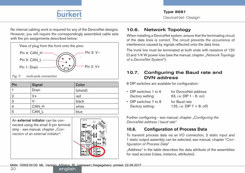
No internal cabling work is required for any of the DeviceNet designs.However, you will require the correspondingly assembled cable sets with the pin assignments described below:
Pin 4: CAN_H
Pin 5: CAN_L
Pin 1: Drain
Pin 3: V–
Pin 2: V+
View of plug from the front onto the pins:
Fig. 7: multi-pole connection
Pin Signal Color1 Drain (shield)
2 V+ red3 V- black4 CAN_H white5 CAN_L blue
An externalinitiatorcan be con-nected using the small 3-pin terminal strip - see manual, chapter „Con-nection of an external initiator“.
10.6. NetworkTopologyWhen installing a DeviceNet system, ensure that the terminating circuit of the data lines is correct. The circuit prevents the occurrence of interference caused by signals reflected onto the data lines.
The trunk line must be terminated at both ends with resistors of 120 Ω and 1/4 W power loss (see the manual, chapter „Network Topology of a DeviceNet System“).
10.7. ConfiguringtheBaudrateandDVNaddress
8 DIP switches are available for configuration:
• DIP switches 1 to 6 for DeviceNet address (factory setting: 63, i.e. DIP 1 - 6: on)
• DIP switches 7 to 8 for Baud rate (factory setting: 125, i.e. DIP 7 + 8: off)
Further configuring - see manual, chapter „Configuring the DeviceNet address / baud rate“
10.8. Configuration of Process DataTo transmit process data via an I/O connection, 2 static input and 1 static output assembly can be selected, see manual, chapter “Con-figuration of Process Data”
„Address“ in the table describes the data attribute of the assemblies for read access (class, instance, attributes).
english
21
DeviceNet-Design
Type 8681
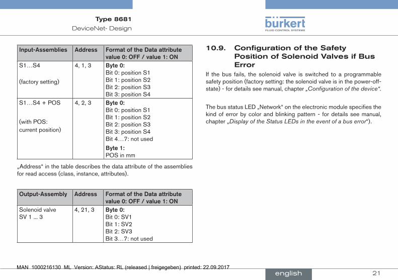
Input-Assemblies Address FormatoftheDataattributevalue0:OFF/value1:ON
S1…S4
(factory setting)
4, 1, 3 Byte0:Bit 0: position S1 Bit 1: position S2 Bit 2: position S3 Bit 3: position S4
S1…S4 + POS
(with POS: current position)
4, 2, 3 Byte0:Bit 0: position S1 Bit 1: position S2 Bit 2: position S3 Bit 3: position S4 Bit 4…7: not used
Byte1:POS in mm
„Address“ in the table describes the data attribute of the assemblies for read access (class, instance, attributes).
Output-Assembly Address FormatoftheDataattributevalue0:OFF/value1:ON
Solenoid valve SV 1 ... 3
4, 21, 3 Byte0:Bit 0: SV1 Bit 1: SV2 Bit 2: SV3 Bit 3…7: not used
10.9. ConfigurationoftheSafetyPositionofSolenoidValvesifBusError
If the bus fails, the solenoid valve is switched to a programmable safety position (factory setting: the solenoid valve is in the power-off-state) - for details see manual, chapter „Configuration of the device“.
The bus status LED „Network“ on the electronic module specifies the kind of error by color and blinking pattern - for details see manual, chapter „Display of the Status LEDs in the event of a bus error“).
english

22
120VAC-Design
Type 8681
11. 120VAC-DESIGN
11.1. Connection
left connection: 1 x M16 x 1,5 cable gland for power supply and signals
right connection: 1 x M16 x 1,5 cable gland for external initiator
11.2. ElectricalDataCentralpowersupply: 110 ... 130 V AC, 50/60 Hz
Powerconsumption(stand-bycurrent): 10 mA at 120 V AC
Solenoidvalves: max. switching capacity 1.7 W (per solenoid valve) typ. continuous output 1.4 W (per solenoid valve) power consumption per solenoid valve: 12 mA at 120 V AC Operation mode: Long-term operation (100 %)
Centraldisplayoftheswitchingstates: 13 mA with a power supply of
120 V AC per illuminated display
Outputs/binaryfeedbacksignals: S1out - S3out Design: NO contact, L switching,
short-circuit protection via auto- matically resetting fuse switchable output current: max. 50 mA per feedback signal Output voltage - active: ≥ (operating voltage - 2 V) - inactive: max. 1 V in unloaded state
Feedbacksignaloutput: S4 out is directly connected to S4 in
Input/proximityswitches(externalinitiator:S4in): Power supply: voltage present at control head UNominal = 120 V AC, 50/60 Hz Design: DC 2- and 3-conductor, NO contact, L-switching input current 1-Signal: ISensor < 2 mA
Valvecontrolinputs(Y1-Y3): Signal level - active: U > 60 V AC Signal level - inactive: U < 20 V AC Impedance: > 40 kOhm
english

23
120VAC-Design
Type 8681
11.3. ElectricalInstallation
WARNING!
Dangerofexplosioninexplosiveatmosphere(zone2)!
• See the note DANGER at chapter “8.3”, page 14!
Riskofinjuryduetoelectricalshock(120VAC)!• When setting the position measuring system (Teach-In), donot
contactanylivecomponents!• Before reaching into the system (except for the Teach-In procedure
in a non-explosive atmosphere) switch off the power supply and secure it to prevent restarting
• Observe applicable accident prevention and safety regulations for electrical equipment!
Riskofinjuryfromimproperinstallation!• the PEconnection must be connected!• Installation may be carried out by authorized technicians only and
with the appropriate tools!
Cablegland:
→ Open the housing.
→ Assemble connection cables for signals and power supply as well as for the external initiator.
→ Insert cables through the respective cable glands into the interior of the housing.
→ Connect the wires to the connection terminals according to the pin assignment described in “Fig. 8”. Fix them.
connection for valve 1 with status
LED
terminal strip 1
service interface
DIP-switches for color coding the LED‘s
terminal strip 2 (external initiator)
Teach-In- buttons T1, T2, T3connections for valve 2, 3 with status LED
Fig. 8: Electronics module (120 V AC)
Terminalstrip1 ConfigurationPE Protection Earth - protective conductorL Power supply
120 V AClive conductor
N neutral conductorS1 OUT Ouput position 1S2 OUT Ouput position 2S3 OUT Ouput position 3 S4 OUT Ouput external initiatorY1 Input solenoid valve 1Y2 Input solenoid valve 2Y3 Input solenoid valve 3
english

24
PositionMeasuringSystem
Type 8681
Terminalstrip2 Configuration(externalinitiator)L Power supply - live conductorS4 IN Input external initiatorN Power supply - neutral conductor
→ Close the housing.
→ Ensure IP protection (dummy plugs).
An externalinitiatorcan be connected using the small 3-pin terminal strip 2 - see manual, chapter „Connection of an external initiator“.
12. POSITIONMEASURINGSYSTEMThe recordable stroke range is between 0 and 80 mm. Three Teach-In buttons have been provided for comparison with the actual stroke range.
12.1. Teach-In → Open the housing (but not in explosive atmosphere!).
→ Supply electrical power.
→ Position the process valve at the lower switching position.
→ Depress the lower Teach-In button (T1) for approx. 1.5 seconds (the LED corresponding to this position will flash quickly three times during the teaching phase). Once this position has been stored, the corresponding LED will remain continuously lit until the position of the piston is changed.
→ Afterwards, position the process valve at the upper switching position to be recorded.
→ Depress the upper Teach-In button (T2) for approx. 1.5 seconds (the LED corresponding to this position will flash quickly three times during the teaching phase). Once this position has been stored, the corresponding LED will remain continuously lit until the position of the piston is changed.
→ The process valve can now be moved into a third, defined position.
→ Depress the middle Teach-In button (T3) for approx. 1.5 seconds (the LED corresponding to this position will flash quickly three times during the teaching phase). Once this position has been stored, the corresponding LED will flash continuously until the position of the piston is changed.
english

25
Start-up
Type 8681
→ If necessary, return control head and system to normal state (switching position, power supply).
→ Close the housing.
12.2. Teach-Reset → Depress the Teach-In button (T1+T2) for ca. 2.5 sec. (optical feedback: Blinking in the fault color)
12.3. AutotuneAutotune functions and Autotune sequences - see operating instructions.
12.4. LED-ColorAssignmentsS1 - green, continuously lit, S2 - yellow, continuously lit, S3 - green, continuously flashing (250 ms/250 ms)
(Delivered state of the DIP switches: 0000)
It is possible to set different color combinations with the help of DIP switches - see the manual, chapter „Settingthecolorcombinations“.
In the event of a fault or in various states, the LED‘s flash in different flashing patterns - see the manual, chapter „Blinkingpattern&faultsignaling“.
If a valve has several overlapping states, a priority list of feedback signal is valid - see the manual, chapter „Signalpriorities“.
13. START-UP
WARNING!
Riskofinjuryfromimproperoperation!
Improper operation may cause injury and damage to the device and its environment. • Before starting-up must be ensured that the contents
of the manual operator is known and understood. • The safety instructions and the intended use must be
followed. • Only adequately trained personnel should take the
plant / the device in operation.
→ Assembly of the control head type 8681.
→ Pneumatic and electrical installation.
→ Setting the position measuring system (Teach-In).
After assembly, installation and setting of the position measuring system according to the operating instructions the control head is ready for operation.
english

26
Packaging,Transport,Storage,Disposal
Type 8681
14. PACKAGING,TRANSPORT,STORAGE,DISPOSAL
NOTE!
Transport/storagedamage!
Inadequately protected equipment may be damaged during transport or storage. • Protect the device during transportation / storage against moisture
and dirt in shock-resistant packaging. • Avoid the effects of heat and cold which could result in tempera-
tures above or below the permitted storage temperature.• Storage temperature: -20 ... +65 °C.
NOTE!
Damagetotheenvironmentcausedbydevicecomponentscontaminatedwithmedia.• Observe the relevant disposal and environmental protection
regulations.
→ Dispose of the device and packaging in an environmentally friendly manner.
→ Observe national waste disposal regulations.
english

27
Typ 8681
1. DERQUICKSTART....................................................................................... 291.1. Begriffsdefinition „Gerät“ .............................................................291.2. Darstellungsmittel ...........................................................................29
2. BESTIMMUNGSGEMÄSSEVERWENDUNG...................................302.1. Beschränkungen ............................................................................30
3. GRUNDLEGENDESICHERHEITSHINWEISE.................................31
4. ALLGEMEINEHINWEISE.......................................................................... 324.1. Kontaktadressen .............................................................................324.2. Gewährleistung...............................................................................324.3. Informationen im Internet ..............................................................32
5. AUFBAUUNDFUNKTION....................................................................... 335.1. Handbetätigung ..............................................................................335.2. Aufbau ...............................................................................................33
6. TECHNISCHEDATEN................................................................................ 346.1. Konformität .....................................................................................346.2. Normen .............................................................................................346.3. Betriebsbedingungen ....................................................................346.4. Mechanische Daten .......................................................................346.5. Pneumatische Daten .....................................................................346.6. Daten Wegmesssystem ................................................................356.7. Elektrische Daten ...........................................................................35
7. MONTAGE/INSTALLATION...................................................................357.1. Sicherheitshinweise .......................................................................35
7.2. Montage ...........................................................................................367.3. Pneumatische Installation .............................................................367.4. Öffnen/Schließen des Gehäuses ...............................................377.5. Elektrische Installation ...................................................................37
8. 24VDC-AUSFÜHRUNG........................................................................ 378.1. Anschlussmöglichkeiten ...............................................................378.2. Elektrische Daten ...........................................................................378.3. Elektrische Installation (24 V DC) ..............................................38
9. AS-I-AUSFÜHRUNG................................................................................ 409.1. Anschlussmöglichkeiten ...............................................................409.2. Anzahl anschließbarer Steuerköpfe ...........................................409.3. Länge der Busleitung ....................................................................409.4. Elektrische Daten ...........................................................................419.5. Elektrische Installation (AS-i) ......................................................41
10. DEVICENET-AUSFÜHRUNG.............................................................4210.1. Anschlussmöglichkeit .................................................................4210.2. Spezifizierung DeviceNet ...........................................................4210.3. Länge der Busleitung ..................................................................4310.4. Elektrische Daten .........................................................................4310.5. Elektrische Installation (DVN) ....................................................4410.6. Netztopologie ................................................................................4510.7. Konfiguration von Baudrate und DVN-Adresse ....................4510.8. Konfiguration der Prozessdaten ...............................................4510.9. Sicherheitsstellung der Magnetventile bei Busfehler ..........46
Inhaltsverzeichnis
deutsch
28
Typ 8681
11. 120VAC-AUSFÜHRUNG................................................................... 4611.1. Anschlussmöglichkeit .................................................................4611.2. Elektrische Daten .........................................................................4611.3. Elektrische Installation ................................................................47
12. WEGMESSSYSTEM..................................................................................4912.1. Teach-In ..........................................................................................4912.2. Teach-Reset ..................................................................................4912.3. Autotune .........................................................................................4912.4. LED - Farbzuordnungen .............................................................49
13. INBETRIEBNAHME...................................................................................50
14. VERPACKUNG,TRANSPORT,LAGERUNG, ENTSORGUNG............................................................................................50
deutsch
29
DerQuickstart
Typ 8681
1. DERQUICKSTARTBewahren Sie diese Anleitung so auf, dass sie für jeden Benutzer gut zugänglich ist und jedem neuen Eigentümer des Gerätes wieder zur Verfügung steht.
WichtigeInformationenzurSicherheit!
Lesen Sie den Quickstart sorgfältig durch. Beachten Sie vor allem die Kapitel „2. Bestimmungsgemäße Verwendung“ und „3. Grundlegende Sicherheitshinweise“.• Der Quickstart muss gelesen und verstanden werden.
Der Quickstart erläutert beispielhaft die Montage und Inbetriebnahme des Gerätes.
Die ausführliche Beschreibung des Gerätes finden Sie in der Bedie-nungsanleitung für den Typ 8681
Die Bedienungsanleitung finden Sie im Internet unter: www.buerkert.de
> Dokumentation > Bedienungsanleitungen/Zulassungen > Typensuche
1.1. Begriffsdefinition„Gerät“Der in dieser Anleitung verwendeten Begriff „Gerät“ steht immer für den Steuerkopf Typ 8681.
1.2. DarstellungsmittelIn dieser Anleitung werden folgende Darstellungsmittel verwendet.
GEFAHR!
WarntvoreinerunmittelbarenGefahr!• Bei Nichtbeachtung sind Tod oder schwere Verletzungen die
Folge.
WARNUNG!
WarntvoreinermöglicherweisegefährlichenSituation!• Bei Nichtbeachtung können schwere Verletzungen oder Tod die
Folge sein.
VORSICHT!
WarntvoreinermöglichenGefährdung!• Nichtbeachtung kann mittelschwere oder leichte Verletzungen
zur Folge haben.
HINWEIS!
WarntvorSachschäden!
Wichtige Zusatzinformationen, Tipps und Empfehlungen
Verweist auf Informationen in dieser Bedienungsanleitung oder in anderen Dokumentationen.
→ Markiert einen Arbeitsschritt, den Sie ausführen müssen.
deutsch

30
BestimmungsgemäßeVerwendung
Typ 8681
2. BESTIMMUNGSGEMÄSSEVERWENDUNG
BeinichtbestimmungsgemäßemEinsatzdesSteuerkopfesTyp8681könnenGefahrenfürPersonen,AnlageninderUmgebungunddieUmweltentstehen.• Der Steuerkopf ist konzipiert für den Einsatz als Ansteuerung
pneumatisch betätigter Prozessventile und / oder für die Erfassung von deren Schaltzuständen.
• Für den Einsatz sind die in den Vertragsdokumenten und der Bedienungsanleitung spezifizierten zulässigen Daten, Betriebs- und Einsatzbedingungen zu beachten.
• Angesichts der Vielzahl von Einsatz- und Verwendungsfällen muss vor dem Einbau geprüft und erforderlichenfalls getestet werden, ob der Steuerkopf für den konkreten Einsatzfall geeignet ist. Wenden Sie sich bei Unklarheiten an Ihr Bürkert Service Center.
• Das Gerät nur in Verbindung mit von Bürkert empfohlenen bzw. zugelassenen Fremdgeräten und -komponenten einsetzen.
• Eigenmächtige Umbauten und Veränderungen am Steuerkopf sind aus Sicherheitsgründen verboten.
• Voraussetzungen für den sicheren und einwandfreien Betrieb sind sachgemäßer Transport, sachgemäße Lagerung und Installation sowie sorgfältige Bedienung und Instandhaltung.
• Für den Anschluss des Steuerkopfes Leitungsinstallationen verwenden, die keine unzulässigen mechanischen Belastungen verursachen.
• Setzen Sie das Gerät nur bestimmungsgemäß ein.
2.1. BeschränkungenBeachten Sie bei der Ausfuhr des Systems/Gerätes gegebenenfalls bestehende Beschränkungen.
deutsch

31
GrundlegendeSicherheitshinweise
Typ 8681
3. GRUNDLEGENDESICHERHEITSHINWEISE
Diese Sicherheitshinweise berücksichtigen keine
• Zufälligkeiten und Ereignisse, die bei Montage, Betrieb und Wartung der Geräte auftreten können.
• ortsbezogenen Sicherheitsbestimmungen, für deren Einhaltung, auch in Bezug auf das Montagepersonal, der Betreiber verantwortlich ist.
GEFAHR
GefahrdurchhohenDruck!• Vor dem Lösen von Leitungen oder Ventilen den Druck abschalten
und Leitungen entlüften.
ExplosionsgefahrinEx-Atmosphäre(Ex-AtmosphärenurimStörfall,daZone2)!• Öffnen der Haube bzw. des Gehäuses unter Ex-Atmosphäre ist
nur im spannungslosen Zustand zulässig!
• Gehäuse durch Verplombung gegen werkzeugloses Öffnen sichern!
• Betätigen der DIP-Schalter auf der Platine, Nutzung der Service-Schnittstelle und der Teach-Tasten ist unter Ex-Atmosphäre nicht zulässig!
• Staubschichten auf dem Gehäuse dürfen 5 mm nicht überschreiten! Es sind Flusen, leitfähige und nicht-leitfähige Stäube zulässig. Das Innere des Gehäuses darf nicht verschmutzt sein!
• Beim Abwischen des Steuerkopfes im Ex-Bereich zur Vermeidung elektro-statischer Aufladungen ein feuchtes oder antistatisches Tuch verwenden!
WARNUNG!
GefahrdurchelektrischeSpannung!• Vor Eingriffen in das Gerät oder die Anlage, Spannung abschal-
ten und vor Wiedereinschalten sichern!• Die geltenden Unfallverhütungs- und Sicherheitsbestimmungen
für elektrische Geräte beachten!
AllgemeineGefahrensituationen.
Zum Schutz vor Verletzungen ist zu beachten:• Dass die Anlage nicht unbeabsichtigt betätigt werden kann.• Installations- und Instandhaltungsarbeiten sowie Bedienhandlun-
gen dürfen nur von autorisiertem, qualifizier tem Fachpersonal mit geeignetem Werkzeug ausgeführt werden.
• Am Gerät keine unzulässigen inneren oder äußeren Veränderungen vornehmen.
• Nach einer Unterbrechung der elektrischen oder pneumatischen Versorgung ist ein definierter oder kontrollierter Wiederanlauf des Prozesses zu gewährleisten.
• Das Gerät darf nur in einwandfreiem Zustand und unter Beachtung der Bedienungsanleitung eingebaut und betrieben werden.
• Für die Einsatzplanung und den Betrieb des Gerätes müssen die allgemeinen Regeln der Technik eingehalten werden.
HINWEIS!
ElektrostatischgefährdeteBauelemente/Baugruppen!
Das Gerät enthält elektronische Bauelemente, die gegen elekt-rostatische Entladung (ESD) empfindlich reagieren. Berührung mit elektrostatisch aufgeladenen Personen oder Gegenständen
deutsch

32
AllgemeineHinweise
Typ 8681
gefährdet diese Bauelemente. Im schlimmsten Fall werden sie sofort zerstört oder fallen nach der Inbetriebnahme aus.
• Anforderungen nach EN 61340-5-1 beachten, um die Möglichkeit eines Schadens durch schlagartige elektrostatische Entladung zu minimieren bzw. zu vermeiden!
• Elektronische Bauelemente nicht bei anliegender Versorgungs-spannung berühren!
HINWEIS!
GefahrvonSachschäden
• In die Medienanschlüsse des Systems keine Flüssigkeiten und keine aggressiven oder brennbaren Medien einspeisen.
• Gehäuse nicht mechanisch belasten (z.B. durch Ablage von schweren Gegenständen oder als Trittstufe).
• Keine unzulässigen äußerlichen Veränderungen an den Gerätege-häusen vornehmen. Gehäuseteile und Schrauben nicht lackieren.
• Den sicher geschlossenen Steuerkopf nur mit materialverträglichen Reinigungsmitteln reinigen und gründlich mit klarem Wasser nachspülen.
Der Steuerkopf Typ 8681 wurde unter Einbeziehung der anerkannten sicherheitstechnischen Regeln entwickelt und entspricht dem Stand der Technik. Trotzdem können Gefahren entstehen.
4. ALLGEMEINEHINWEISE
4.1. KontaktadressenDeutschland
Bürkert Fluid Control Systems Sales Center Christian-Bürkert-Str. 13-17 D-74653 Ingelfingen Tel. + 49 (0) 7940 - 10 91 111 Fax + 49 (0) 7940 - 10 91 448 E-mail: [email protected]
International
Weitere Kontaktmöglichkeiten finden Sie im Internet unter:
www.burkert.com
4.2. GewährleistungVoraussetzung für die Gewährleistung ist der bestimmungsgemäße Gebrauch des Steuerkopfes Typ 8681 unter Beachtung der spezifi-zierten Einsatzbedingungen.
4.3. InformationenimInternetBedienungsanleitungen und Datenblätter zum Typ 8681 finden Sie im Internet unter:
www.buerkert.de
> Dokumentation > Bedienungsanleitungen/Zulassungen > Typensuche
deutsch

33
AufbauundFunktion
Typ 8681
5. AUFBAUUNDFUNKTIONDer Steuerkopf Typ 8681 ist konzipiert für den Einsatz als Ansteuerung pneumatisch betätigter Prozessventile und / oder für die Erfassung von deren Schaltzuständen.
Zur Erfassung der Prozessventilschaltstellungen und deren Rück-meldung an eine übergeordnete Steuerung ist der Steuerkopf mit einem berührungslosen Wegmesssystem ausgestattet, welches mit 3 ein-stellbaren diskreten Rückmeldesignalen arbeitet (Teach-In-Funktion).
Es sind verschiedene pneumatische und elektrische Anschlussvari-anten verfügbar.
Positionen und Statusinformationen können mittels 3 Signalfarben angezeigt werden.
5.1. HandbetätigungDer Steuerkopf stellt standardmäßig zur Verfügung:
• eine leicht von außen zugängliche magnetische Handbetätigung auf Basis codierter Magnetfelder für das Magnetventil 1 (Anschluss 2/A1) sowie
• eine bei geöffneter Haube zugängliche mechanische Handbetä-tigung an jedem bestückten Magnetventil.
5.2. Aufbau
Pneuma- tische Anschlüsse
Ansatzschrauben (2 x M5) - keine Dichtungsfunktion, sondern Sicherung gegen Abziehen vom Aufnahmeflansch
Elektrische Anschlüsse (Kabelverschrau-bungen)
Verplombungs- nase
Elektronikmodul (mit Serviceschnitt-stelle, Klemmleisten, DIP, Teach-In-Tasten)
Wegmesssystem mit LED‘s
Drosselschrauben der Magnetventile (MV)
mechanische Hand-betätigung am MV (roter Hebel)
Bild 1: Aufbau
deutsch

34
TechnischeDaten
Typ 8681
6. TECHNISCHEDATEN
6.1. KonformitätDer Steuerkopf Typ 8681 ist konform zu den EG-Richtlinien entspre-chend der EG-Konformitätserklärung.
6.2. NormenDie angewandten Normen, mit denen die Konformität mit den EG-Richt-linien nachgewiesen wird, sind in der EG-Baumusterprüfbescheinigung und/oder der EG-Konformitätserklärung nachzulesen.
Für den jeweiligen Steuerkopf gelten die Angaben auf dem jeweiligen Typschild. Die auf dem Typschild ersichtlichen Symbole zeigen die geltenden Richtlinien bzw. Zulassungen an.
6.3. BetriebsbedingungenStandardversion:Umgebungstemp.: -10 ... +55 °C
Schutzart: IP65 / IP67 nach EN 60529 bzw. IP69K nach IEC 40050-9
VersionfürEinsatzinEx-Atmosphäre,Zone2: Umgebungstemp.: +5 ... +55 °C
Schutzart: IP64 nach EN 60529 und Anforderungen EN 60079-0: 2009
Bei Einsatz in Ex-Atmosphäre (Zone 2) muss die Installation der Geräte in geschützter Einbaulage gemäß IEC/EN 60079-0 erfolgen.
6.4. MechanischeDatenMaße: siehe Datenblatt
Gehäusematerial: außen: PA, PC, PPO, VA innen: ABS, PA, PMMA
Dichtungsmaterial: außen: CR, EPDM innen: EPDM, FKM, NBR
6.5. PneumatischeDatenSteuermedium: Luft, neutrale Gase: Qualitätsklassen nach
ISO 8573-1 (Filter 5 µm empfohlen)
Staubgehalt max. Teilchengröße 40 µm, (Qualitätskl. 7) max. Teilchendichte 10 mg/m3
Wassergehalt max. Drucktaupunkt -20 °C oder (Qualitätskl. 3) min. 10 °C unterhalb der niedrigsten Betriebstemperatur
Ölgehalt (Qualitätskl. X) max. 25 mg/m3
TemperaturbereichderDruckluft: -10 ... +50 °C
Druckbereich: 2,5 ... 8 bar
LuftleistungMagnetventil: 110 IN/min (für Be-, Ent-, Anlüftung)
(110 IN/min - Lieferzustand 200 IN/min - max. typischer Durchfluss) (QNn-Wert nach Definition bei Druckabfall von 7 auf 6 bar absolut bei +20 °C)
deutsch
35
Montage/Installation
Typ 8681
Anschlüsse: Zu- und Abluftanschluss G1/4 Arbeitsanschlüsse G1/8
6.6. DatenWegmesssystemHubbereich: 0 ... 80 mm
Auflösung: ≤ 0,1 mm
Gesamtfehler: ± 0,5 mm (bei Verwendung eines geeigneten Targets)
6.7. ElektrischeDatensiehe Kapitel: „8. 24 V DC - Ausführung“,
„9. AS-I - Ausführung“, „10. DeviceNet - Ausführung“, „11. 120 V AC - Ausführung“.
7. MONTAGE/INSTALLATION
7.1. Sicherheitshinweise
GEFAHR!
VerletzungsgefahrdurchhohenDruckinderAnlage!• Vor dem Lösen von Leitungen oder Ventilen den Druck abschalten
und Leitungen entlüften.
ExplosionsgefahrinEx-Atmosphäre(Ex-AtmosphärenurimStörfall,daZone2)!• Öffnen der Haube bzw. des Gehäuses unter Ex-Atmosphäre ist
nur im spannungslosen Zustand zulässig!
WARNUNG!
VerletzungsgefahrdurchStromschlag!• Vor Eingriffen in das Gerät oder die Anlage, Spannung abschalten
und vor Wiedereinschalten sichern!• Die geltenden Unfallverhütungs- und Sicherheitsbestimmungen
für elektrische Geräte beachten!
VerletzungsgefahrbeiunsachgemäßerMontage!• Die Montage darf nur autorisiertes Fachpersonal mit geeignetem
Werkzeug durchführen!
VerletzungsgefahrdurchungewolltesEinschaltenderAnlageundunkontrolliertenWiederanlauf!• Anlage vor unbeabsichtigtem Betätigen sichern.• Nach der Montage einen kontrollierten Wiederanlauf gewährleisten.
deutsch
36
Montage/Installation
Typ 8681
7.2. MontageZur Montage des Steuerkopfes Typ 8681 an ein Prozessventil benötigen Sie einen prozessventilspezifischen Aufnahmeflansch als Adapter. Der Aufnahmeflansch muss der Bauform des Prozessventiles angepasst sein.
→ Die Kolbenstange mit Target auf die Prozessventilspindel montieren. Referenzmaße beachten!
→ Aufnahmeflansch auf dem Prozessventil befestigen. Dabei die Zentrierung und die Abdichtungsbedingungen beachten!
→ Sitz der beiden Dichtungsringe (in oberster und unterster Nut) prüfen.
→ Steuerkopf auf den Aufnahmeflansch montieren (stufenlos 360° drehbar).
→ Steuerkopf mit den zwei Sicherungsschrauben (Ansatzschrauben M5, Anzugsdrehmoment max. 3,2 Nm) in der mittleren Nut des Aufnahmeflansches sichern (siehe Bedienungsanleitung).
7.3. PneumatischeInstallation → Die benötigten Arbeitsanschlüsse 2/A1 bis 2/A3 (je nach Variante) mit den zugehörigen Anschlüssen des Prozessventils verbinden.
→ Versorgungsleitung mit dem Versorgungsdruckanschluss 1/P (2,5 … 8 bar) verbinden.
→ Am Abluftanschluss (3/R) ist im Lieferzustand bereits ein Schall-dämpfer montiert.
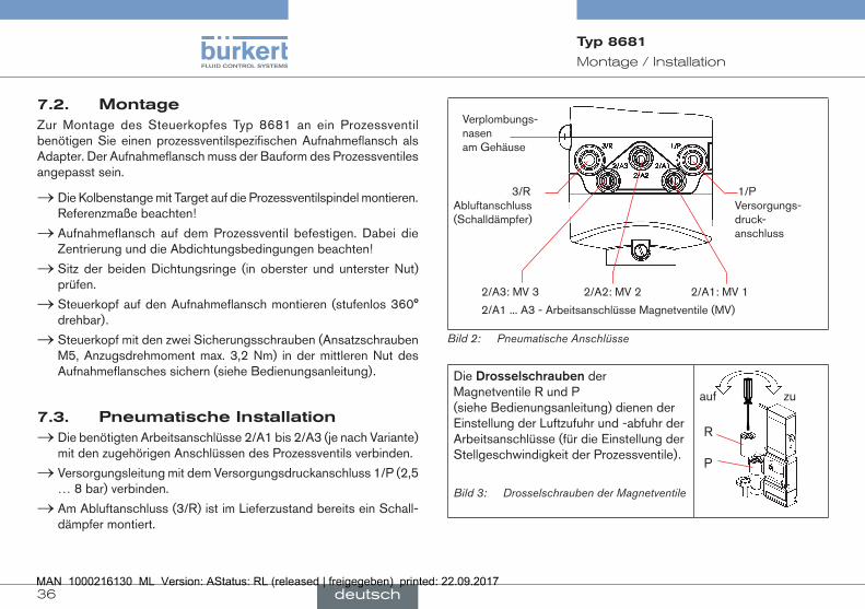
1/P Versorgungs-druck- anschluss
3/R Abluftanschluss (Schalldämpfer)
2/A3: MV 3 2/A2: MV 2 2/A1: MV 1
2/A1 ... A3 - Arbeitsanschlüsse Magnetventile (MV)
Verplombungs-nasen am Gehäuse
Bild 2: Pneumatische Anschlüsse
Die Drosselschrauben der Magnetventile R und P (siehe Bedienungsanleitung) dienen der Einstellung der Luftzufuhr und -abfuhr der Arbeitsanschlüsse (für die Einstellung der Stellgeschwindigkeit der Prozessventile).
Bild 3: Drosselschrauben der Magnetventile
R P
auf zu
deutsch

37
24VDC-Ausführung
Typ 8681
7.4. Öffnen/SchließendesGehäusesÖffnen:
→ Verplombung lösen, falls Gehäuse gesichert.
→ Kunststoffhaube durch Drehen gegen den Uhrzeigersinn (bis Anschlag, ca. 1,5 cm) öffnen.
Schließen:
→ Kunststoffhaube so auf das Unterteil aufsetzen, dass die inneren „Nasen“ über den Befestigungsnuten liegen und die äußeren Verplombungsnasen fast übereinander liegen. Haube vollständig über die Dichtung des Unterteiles drücken.
→ Drehen der Haube um ca. 1,5 cm im Uhrzeigersinn (bzw. bis Ver-plombungsnasen übereinander liegen).
Im Ex-Bereich wird eine Verplombung der Haube gefordert!
7.5. ElektrischeInstallationsiehe Kapitel: „8. 24 V DC - Ausführung“,
„9. AS-I - Ausführung“, „10. DeviceNet - Ausführung“, „11. 120 V AC - Ausführung“.
8. 24VDC-AUSFÜHRUNG
8.1. Anschlussmöglichkeiten
Anschluss links: 1 x M16 x 1,5 Kabelverschrau- bung für Spannungsversorgung und Signale
Anschluss links: 1 x M16 x 1,5 Kabelverschrau- bung mit Multipolanschluss (M12-Stecker nach IEC 61076-2-101, 12-polig) an Kabel von 8 cm
Anschluss rechts: 1 x M16 x 1,5 Kabelverschrau- bung für externen Initiator
Anschluss rechts: 1 x M16 x 1,5 Kabelverschrau- bung für externen Initiator
8.2. ElektrischeDatenSpannungs-versorgung: 12 ... 28 V DC, Restwelligkeit 10 %
Stromaufnahme(Ruhestrom): 30 mA bei 24 V DC
deutsch
38
24VDC-Ausführung
Typ 8681
Magnetventile: Max. Schaltleistung max. 0,9 W (je Magnetventil) Typ. Dauerleistung 0,6 W (je Magnetventil) Betriebsart: Dauerbetrieb (100 % ED)
ZentraleAnzeigederSchaltzustände: 42 mA bei Spannungsversorgung 24 V DC je dargestellter Leuchtanzeige
Ausgänge/binäreRückmeldesignale: S1 out - S4 out Bauart: Schließer (normally open),
PNP-Ausgang; kurzschlussfest, schaltbarer Ausgangsstrom: max. 100 mA je Rückmeldesignal
Eingang/Näherungsschalter(externerInitiator:S4in): Spannungs- angelegte Spannung am
versorgung: Steuerkopf - 10 %
Strombelastbarkeit Sensorversorgung: max. 90 mA; Kurzschlussschutz
Bauart: DC 2- und 3-Draht, NO od. NC; PNP-Ausgang
EingängeVentilansteuerung(Y1-Y3): Signalpegel - aktiv: U > 10 V, max. 24 V DC + 10%
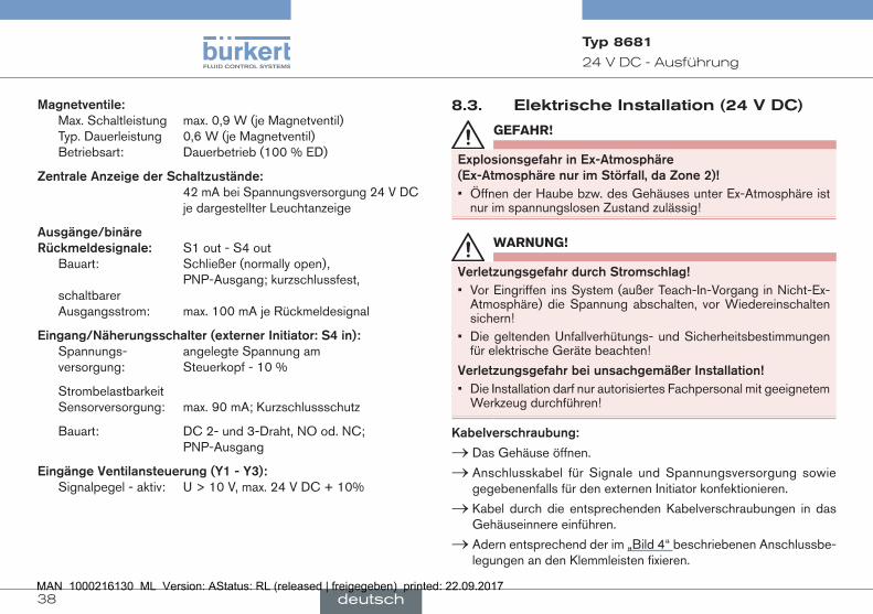
8.3. ElektrischeInstallation(24VDC)
GEFAHR!
ExplosionsgefahrinEx-Atmosphäre(Ex-AtmosphärenurimStörfall,daZone2)!• Öffnen der Haube bzw. des Gehäuses unter Ex-Atmosphäre ist
nur im spannungslosen Zustand zulässig!
WARNUNG!
VerletzungsgefahrdurchStromschlag!• Vor Eingriffen ins System (außer Teach-In-Vorgang in Nicht-Ex-
Atmosphäre) die Spannung abschalten, vor Wiedereinschalten sichern!
• Die geltenden Unfallverhütungs- und Sicherheitsbestimmungen für elektrische Geräte beachten!
VerletzungsgefahrbeiunsachgemäßerInstallation!• Die Installation darf nur autorisiertes Fachpersonal mit geeignetem
Werkzeug durchführen!
Kabelverschraubung:
→ Das Gehäuse öffnen.
→ Anschlusskabel für Signale und Spannungsversorgung sowie gegebenenfalls für den externen Initiator konfektionieren.
→ Kabel durch die entsprechenden Kabelverschraubungen in das Gehäuseinnere einführen.
→ Adern entsprechend der im „Bild 4“ beschriebenen Anschlussbe-legungen an den Klemmleisten fixieren.
deutsch

39
24VDC-Ausführung
Typ 8681
Anschluss mit Status-LED für Magnetventil V1
Klemm- leiste 1
Service- Schnittstelle
DIP-Schalter zur Farbcodierung der LED‘s
Klemmleiste 2 (externer Initi-ator)
Teach-In- Tasten T1-3
Anschlüsse mit Status-LED für V2, V3
Bild 4: Elektronikmodul (24 V DC)
Klemmleiste1 Belegung
24 V Spannungsversorgung 24 V
GND GND
S1 OUT Ausgang Position 1
S2 OUT Ausgang Position 2
S3 OUT Ausgang Position 3
S4 OUT Ausgang externer Initiator
Y1 Eingang Magnetventil 1
Y2 Eingang Magnetventil 2
Y3 Eingang Magnetventil 3
Klemmleiste2 Belegung
24 V Spannungsversorg. 24 V DC für externen Initiator
S4 IN Eingang externer Initiator
GND GND externer Initiator
→ Gehäuse schließen
→ Sicherstellung des IP-Schutzes (Blindstopfen)
KabelverschraubungmitMultipolanschluss:
Bei Varianten mit Multipolanschluss sind keine internen Verkabelungs-arbeiten notwendig. Sie benötigen allerdings entsprechend konfektio-nierte bzw. montierte Kabelsätze mit folgender Pin-Belegung:
Pin Bezeichnung Belegung
1 24 V Spannungsversorgung 24 V
2 GND GND
3 S1 OUT Ausgang Position 1
4 S2 OUT Ausgang Position 2
5 S3 OUT Ausgang Position 3
6 S4 OUT Ausgang externer Initiator S4
7 Y1 Eingang Magnetventil 1
8 Y2 Eingang Magnetventil 2
9 Y3 Eingang Magnetventil 3
10-12 nicht belegt
deutsch

40
AS-I-Ausführung
Typ 8681
Ein externer Initiator kann über die 3-fach-Klemmleiste 2 ange-schlossen werden (siehe „Bild 4“ bzw. siehe Bedienungsanleitung, Kapitel „Anschluss eines Externen Initiators“).
Ein- und Ausgangssignale zur übergeordneten Steuerung (SPS):
Pin 9 - Y3
Pin 8 - Y2
12Pin 6 - S4 out
Pin 7 - Y1
Pin 1 - 24 V
Pin 5 - S3 out
Pin 4 - S2 out11
Pin 3 - S1 out Pin 2 - GND
10
Bild 5: Multipolanschluss 24 V DC (12-poliger Rundsteckverbinder M12 x 1,0 - male nach IEC 61076-2-101 — Blick auf Steckerstifte)
9. AS-I-AUSFÜHRUNG
9.1. Anschlussmöglichkeiten
linker Anschluss: 1 x M16 x 1,5 Kabelverschraubung mit Multipolanschluss (M12-Stecker nach IEC 61076-2-101, 4-polig) an Kabel von 8cmoder80cm Länge
rechter Anschluss: 1 x M16 x 1,5 Kabelverschraubung für externen Initiator
9.2. AnzahlanschließbarerSteuerköpfeBei der AS-Interface-Version mit erweitertem Adressbereich (A/B-Slave) kann 1 Master mit 62 Slaves kommu nizieren.
Bei der AS-Interface-Version mit Adressbereich 31 Slaves können maximal 31 Steuerköpfe an eine Busleitung angeschlossen werden (Restriktion Adress bereich).
9.3. LängederBusleitungDas Buskabel darf maximal 100 m lang sein. Bei der Anlagenauslegung muss die Länge des unmittelbar zum Steuerkopf führenden Rundkabels berücksichtigt werden (siehe Beispielrechnung in Bedienungsanleitung).
deutsch
41
AS-I-Ausführung
Typ 8681
9.4. ElektrischeDaten
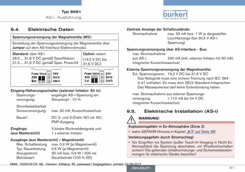
SpannungsversorgungderMagnetventile(MV):
Einstellung der Spannungsversorgung der Magnetventile über Jumperauf dem AS-Interface-Elektronikmodul.
Standard:über AS-i 29,5 ... 31,6 V DC gemäß Spezifikation; 21,0 ... 31,6 V DC gemäß Spez. Power24
Option:extern
(19,2 V DC bis 31,6 V DC)
Eingang/Näherungsschalter(externerInitiator:S4in): Spannungs- angelegte AS-i-Spannung am
versorgung: Steuerkopf - 10 %
Strombelastbarkeit Sensorversorgung: max. 30 mA; Kurzschlussschutz
Bauart: DC 2- und 3-Draht, NO od. NC; PNP-Ausgang
Eingänge: 3 binäre Rückmeldesignale und(ausMastersicht) 1 x externer Initiator
Ausgänge(ausMastersicht)/Magnetventil: Max. Schaltleistung max. 0,9 W (je Magnetventil) Typ. Dauerleistung 0,6 W (je Magnetventil) Anzugsstrom: 30 mA bzw. 0,9 W / 200 ms Betriebsart: Dauerbetrieb (100 % ED)
ZentraleAnzeigederSchaltzustände: Stromaufnahme max. 33 mA bzw. 1 W je dargestellter Leuchtanzeige (bei 30,5 V AS-i- Spannung)
SpannungsversorgungüberAS-Interface-Bus: max. Stromaufnahme aus AS-i: 200 mA (inkl. externer Initiator mit 30 mA) integrierter Kurzschlussschutz
ExterneSpannungsversorgungderMagnetventile: Ext. Spannungsvers.: 19,2 V DC bis 31,6 V DC Das Netzgerät muss eine sichere Trennung nach IEC 364-
4-41 enthalten. Es muss dem SELV-Standard entsprechen. Das Massepotential darf keine Erdverbindung haben.
max. Stromaufnahme aus externer Spannungs- versorgung: ≤ 110 mA bei 24 V DC integrierter Kurzschlussschutz
9.5. ElektrischeInstallation(AS-i)
WARNUNG!
ExplosionsgefahrinEx-Atmosphäre(Zone2)• siehe GEFAHR-Hinweis in Kapitel „8.3“ auf Seite 38!
VerletzungsgefahrdurchStromschlag!• Vor Eingriffen ins System (außer Teach-In-Vorgang in Nicht-Ex-
Atmosphäre) die Spannung abschalten, vor Wiedereinschalten sichern! Die geltenden Unfallverhütungs- und Sicherheitsbestim-mungen für elektrische Geräte beachten!
deutsch
42
DeviceNet-Ausführung
Typ 8681
VerletzungsgefahrbeiunsachgemäßerInstallation!• Die Installation darf nur autorisiertes Fachpersonal mit geeignetem
Werkzeug durchführen!
Bei Varianten mit Multipolanschluss sind keine internen Verkabelungs-arbeiten notwendig. Sie benötigen allerdings entsprechend konfek-tionierte bzw. montierte Kabelsätze mit folgenden Pin-Belegungen.
Pin 2
Pin 3 Pin 1
Pin 4
Bild 6: Multipolanschluss AS-i
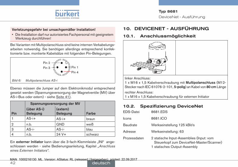
Ebenso müssen die Jumper auf dem Elektronikmodul entsprechend gesetzt werden (Spannungsversorgung der Magnetventile (MV) über AS-i-Bus oder extern) - siehe Seite 41).
SpannungsversorgungderMV
Pin
(überAS-i)Belegung
(extern)Belegung
Farbe
1 AS-i+ AS-i+ braun
2 n.b. GND weiß3 AS-i- AS-i- blau4 n.b. 24 V+ schwarz
Ein externerInitiator kann über die 3-fach-Klemmleiste „INI“ ange-schlossen werden - siehe Bedienungsanleitung, Kapitel „Anschluss eines Externen Initiators“.
10. DEVICENET-AUSFÜHRUNG
10.1. Anschlussmöglichkeit
linker Anschluss: 1 x M16 x 1,5 Kabelverschraubung mit Multipolanschluss (M12-Stecker nach IEC 61076-2-101, 5-polig) an Kabel von 80cm Länge
rechter Anschluss: 1 x M16 x 1,5 Kabelverschraubung für externen Initiator
10.2. SpezifizierungDeviceNetEDS-Datei 8681.EDS
Icons 8681.ICO
Baudrate Werkseinstellung 125 kBit/s
Adresse Werkseinstellung: 63
Prozessdaten 2 statische Input-Assemblies (Input: vom Steuerkopf zum DeviceNet-Master/Scanner) 1 statisches Output-Assembly
deutsch
43
DeviceNet-Ausführung
Typ 8681
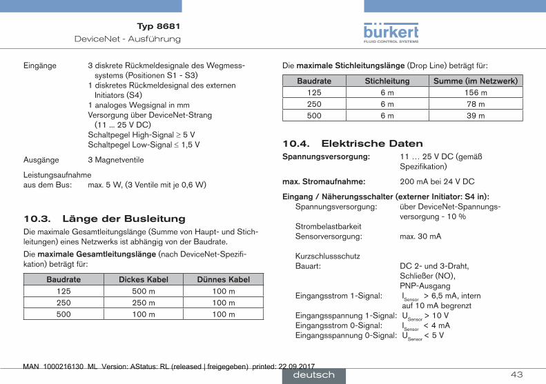
Eingänge 3 diskrete Rückmeldesignale des Wegmess- systems (Positionen S1 - S3) 1 diskretes Rückmeldesignal des externen Initiators (S4) 1 analoges Wegsignal in mm Versorgung über DeviceNet-Strang (11 ... 25 V DC) Schaltpegel High-Signal ≥ 5 V Schaltpegel Low-Signal ≤ 1,5 V
Ausgänge 3 Magnetventile
Leistungsaufnahme aus dem Bus: max. 5 W, (3 Ventile mit je 0,6 W)
10.3. LängederBusleitungDie maximale Gesamtleitungslänge (Summe von Haupt- und Stich-leitungen) eines Netzwerks ist abhängig von der Baudrate.
Die maximale Gesamtleitungslänge (nach DeviceNet-Spezifi-kation) beträgt für:
Baudrate DickesKabel DünnesKabel125 500 m 100 m250 250 m 100 m500 100 m 100 m
Die maximale Stichleitungslänge (Drop Line) beträgt für:
Baudrate Stichleitung Summe(imNetzwerk)125 6 m 156 m250 6 m 78 m500 6 m 39 m
10.4. ElektrischeDatenSpannungsversorgung: 11 … 25 V DC (gemäß Spezifikation)
max.Stromaufnahme: 200 mA bei 24 V DC
Eingang/Näherungsschalter(externerInitiator:S4in): Spannungsversorgung: über DeviceNet-Spannungs-
versorgung - 10 % Strombelastbarkeit Sensorversorgung: max. 30 mA Kurzschlussschutz Bauart: DC 2- und 3-Draht, Schließer (NO), PNP-Ausgang Eingangsstrom 1-Signal: ISensor > 6,5 mA, intern auf 10 mA begrenzt Eingangsspannung 1-Signal: USensor > 10 V Eingangsstrom 0-Signal: ISensor < 4 mA Eingangsspannung 0-Signal: USensor < 5 V
deutsch
44
DeviceNet-Ausführung
Typ 8681
Eingänge (aus Mastersicht) / binärebzw.analogeRückmel-designale:Die Gewinnung der 3 binär zurückgemeldeten Ventilpositionen bzw. des analogen Wegsignals ist in der Bedienungsanleitung im Kapitel „Wegmesssystem“ beschrieben.
Ausgänge(ausMastersicht)/Magnetventile: Max. Schaltleistung 1,0 W (pro Magnetventil) Typ. Dauerleistung 0,6 W (pro Magnetventil) Leistungsabsenkung über DeviceNet-Elektronik integriert Anzugsstrom 120 mA typ. / 200 ms
(3 Ventile) Haltestrom 100 mA typ. bei 24 V DC (3 Ventile) Betriebsart Dauerbetrieb (100 % ED)
ZentraleAnzeigederSchaltzustände: Stromaufnahme aus DeviceNet bei 24 V DC ca. 42 mA bzw. 1 W je dargestellter Leuchtanzeige
10.5. ElektrischeInstallation(DVN)
GEFAHR!
ExplosionsgefahrinEx-Atmosphäre(Ex-AtmosphärenurimStörfall,daZone2)!• Öffnen der Haube bzw. des Gehäuses unter Ex-Atmosphäre ist
nur im spannungslosen Zustand zulässig!
WARNUNG!
VerletzungsgefahrdurchStromschlag!• Vor Eingriffen ins System (außer Teach-In-Vorgang in Nicht-Ex-
Atmosphäre) die Spannung abschalten, vor Wiedereinschalten sichern! Die geltenden Unfallverhütungs- und Sicherheitsbestim-mungen für elektrische Geräte beachten!
VerletzungsgefahrbeiunsachgemäßerInstallation!• Die Installation darf nur autorisiertes Fachpersonal mit geeignetem
Werkzeug durchführen!
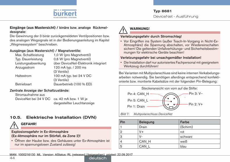
Bei Varianten mit Multipolanschluss sind keine internen Verkabelungs-arbeiten notwendig. Sie benötigen allerdings entsprechend konfekti-onierte bzw. montierte Kabelsätze mit der folgenden Pin-Belegung:
Pin 4: CAN_H
Pin 5: CAN_L
Pin 1: Drain
Pin 3: V–
Pin 2: V+
Steckeransicht von vorn auf die Stifte:
Bild 7: Multipolanschluss DeviceNet
Pin Belegung Farbe1 Drain (Schirm)2 V+ rot3 V- schwarz4 CAN_H weiß5 CAN_L blau
deutsch

45
DeviceNet-Ausführung
Typ 8681
Ein externerInitiatorkann über die 3-fach-Klemmleiste angeschlossen werden - siehe Bedienungsanleitung, Kap. „Anschluss eines Externen Initiators“.
10.6. NetztopologieBei der Installation eines DeviceNet-Systems ist auf die korrekte Abschlussbeschaltung der Datenleitungen zu achten. Die Beschaltung verhindert die Entstehung von Störungen durch Signalreflexionen auf den Datenleitungen.
Die Hauptleitung ist dazu an beiden Enden mit Widerständen von je 120 Ω und 1/4 W Verlustleistung abzuschließen (siehe Bedienungs-anleitung, Kap. „Netztopologie eines DeviceNet-Systems“).
10.7. KonfigurationvonBaudrateundDVN-Adresse
Zur Konfigurierung sind 8 DIP-Schalter vorhanden:
• DIP-Schalter 1 bis 6 für die DeviceNet-Adresse (Werkseinstellung: 63, d. h. DIP 1 - 6: on/ein)
• DIP-Schalter 7 bis 8 für die Baudrate (Werkseinstellung: 125, d. h. DIP 7 + 8: aus)
Weitere Einstellungen - siehe Bedienungsanleitung, Kap. „Konfigu-rieren der DeviceNet-Adresse / Baudrate“.
10.8. KonfigurationderProzessdatenZur Übertragung von Prozessdaten über eine I/O-Verbin dung stehen 2 statische Input- und 1 statisches Output-Assembly zur Auswahl - Details siehe Bedienungsanleitung, Kapitel „Konfiguration der Prozessdaten“.
„Adresse“ in der Tabelle beschreibt das Datenattribut der Assemblies für Lesezugriff (Class, Instance, Attribute).
Input-Assemblies Adresse FormatdesDatenattributsWert0:OFF/Wert1:ON
S1…S4
(Werkseinstellung)
4, 1, 3 Byte0:Bit 0: Position S1 Bit 1: Position S2 Bit 2: Position S3 Bit 3: Position S4
S1…S4 + POS
(mit POS: Ist-Position (Actual Position))
4, 2, 3 Byte0:Bit 0: Position S1 Bit 1: Position S2 Bit 2: Position S3 Bit 3: Position S4 Bit 4…7: nicht benutzt
Byte1:POS in mm
„Adresse“ in der Tabelle beschreibt das Datenattribut der Assemblies für Lesezugriff (Class, Instance, Attribute).
deutsch
46
120VAC-Ausführung
Typ 8681
Output-Assembly Adresse FormatdesDatenattributsWert0:OFF/Wert1:ON
Magnetventil 1 ... 3 4, 21, 3 Byte0:Bit 0: MV1 Bit 1: MV2 Bit 2: MV3 Bit 3…7: nicht benutzt
10.9. SicherheitsstellungderMagnetventilebeiBusfehler
Bei Busausfall wird das Magnetventil in eine programmierbare Sicher-heitsstellung geschaltet (Default: Magnet ventil stromlos) - Details siehe Bedienungsanleitung, Kapitel „Konfiguration des Gerätes“.
Die Bus-Status-LED „Network“ auf dem Elektronikmodul gibt durch Farbe und Blinkmuster genauere Hinweise auf die Art des Fehlers - Details siehe Bedienungsanleitung, Kapitel „Anzeige der Status-LEDs bei Busfehler“).
11. 120VAC-AUSFÜHRUNG
11.1. Anschlussmöglichkeit
linker Anschluss: 1 x M16 x 1,5 Kabelverschraubung für Spannungsversorgung und Signale
rechter Anschluss: 1 x M16 x 1,5 Kabelverschraubung für externen Initiator
11.2. ElektrischeDatenZentraleSpannungs-versorgung: 110 ... 130 V AC, 50/60 Hz
Stromaufnahme(Ruhestrom): 10 mA bei 120 V AC
Magnetventile: Max. Schaltleistung 1,7 VA (je Magnetventil) Typ. Dauerleistung 1,4 VA (je Magnetventil) Stromaufnahme: 12 mA bei 120 V AC (je Magnetventil) Betriebsart: Dauerbetrieb (100 % ED)
ZentraleAnzeigederSchaltzustände: 13 mA bei Spannungsversorgung 120 V
AC je dargestellter Leuchtanzeige
deutsch

47
120VAC-Ausführung
Typ 8681
Ausgänge/binäreRückmeldesignale: S1out - S3out Bauart: Schließer (NO), L-schaltend,
Kurzschlussschutz durch selbstrückstellende Sicherung schaltbarer Ausgangsstrom: max. 50 mA je Rückmeldesignal Ausgangsspannung - aktiv: ≥ (Betriebsspannung - 2 V) Ausgangsspannung - inaktiv: max. 1 V im unbelasteten Zustand
AusgangRückmelde-signal: S4 out ist direkt mit S4in verbunden
Eingang/Näherungsschalter(externerInitiator:S4in): Spannungsversorg.: angelegte Spannung am Steuer-
kopf UNenn = 120 VAC, 50/60 Hz Bauart: DC 2- und 3-Draht, Schließer (NO), L-schaltend Eingangsstrom 1-Signal: ISensor < 2 mA
EingängeVentilansteuerung(Y1-Y3): Signalpegel - aktiv: U > 60 V AC Signalpegel - inaktiv: U < 20 V AC Impedanz: > 40 kOhm
11.3. ElektrischeInstallation
WARNUNG!
ExplosionsgefahrinEx-Atmosphäre(Zone2)
• siehe GEFAHR-Hinweis in Kapitel „8.3“ auf Seite 38!
VerletzungsgefahrdurchStromschlag(120VAC)!• Beim Einstellen des Wegmesssystems (Teach-in) keine span-
nungsführendenBauteileberühren!• Vor Eingriffen ins System (außer Teach-In-Vorgang in Nicht-Ex-
Atmosphäre) die Spannung abschalten, vor Wiedereinschalten sichern!
• Die geltenden Unfallverhütungs- und Sicherheitsbestimmungen für elektrische Geräte beachten!
VerletzungsgefahrbeiunsachgemäßerInstallation!• Der PE-Anschluss muss angeschlossen sein!• Die Installation darf nur autorisiertes Fachpersonal mit geeignetem
Werkzeug durchführen!
Kabelverschraubung:
→ Das Gehäuse öffnen.
→ Anschlusskabel für Signale und Spannungsversorgung sowie gegebenenfalls für den externen Initiator konfektionieren.
→ Kabel durch die entsprechenden Kabelverschraubungen in das Gehäuseinnere einführen.
→ Adern entsprechend der im „Bild 8“ beschriebenen Anschluss-belegungen an den Klemmleisten fixieren.
deutsch

48
120VAC-Ausführung
Typ 8681
Anschluss mit Status-LED für MV1
Klemm- leiste 1
Service- Schnittstelle
DIP-Schalter zur Farb- codierung der LED‘s
Klemmleiste 2 (externer Initiator)
Teach-In- Tasten T2, T3, T1Anschlüsse mit Status-LED für MV2, 3
Bild 8: Elektronikmodul (120 V AC)
Klemmleiste1 BelegungPE Schutzleiter Protection EarthL Spannungsver-
sorgung 120 V ACLeiter
N NullleiterS1 OUT Ausgang Position 1S2 OUT Ausgang Position 2S3 OUT Ausgang Position 3 S4 OUT Ausgang externer InitiatorY1 Eingang Magnetventil 1Y2 Eingang Magnetventil 2Y3 Eingang Magnetventil 3
Klemmleiste2 Belegung(externerInitiator)L Spannungsversorgung - LeiterS4 IN Eingang externer InitiatorN Spannungsversorgung - Nullleiter
→ Gehäuse schließen.
→ Sicherstellung des IP-Schutzes (Blindstopfen)
Ein externer Initiator kann über die Klemmleiste 2 angeschlossen werden - siehe Bedienungsanleitung, Kapitel „Anschluss eines Externen Initiators“.
deutsch

49
Wegmesssystem
Typ 8681
12. WEGMESSSYSTEMDer erfassbare Hubbereich beträgt 0 ... 80 mm.
Für den Abgleich auf den realen Hubbereich sind 3 Teach-In-Tasten vorgesehen.
12.1. Teach-In → Das Gehäuse öffnen (nicht in Ex-Atmosphäre!).
→ Spannungsversorgung herstellen
→ Prozessventil in die untere Schaltposition fahren.
→ Untere Teach-In-Taste (T1) ca. 1,5 s gedrückt halten (entsprechende LED blinkt 3 mal kurz auf). Ist diese Position abgespeichert, leuchtet die entsprechende LED dauerhaft, bis die Position des Hubkolbens verändert wird.
→ Danach Prozessventil in die obere zu erfassende Schaltposition fahren.
→ Obere Teach-In-Taste (T2) ca. 1,5 s gedrückt halten (entsprechende LED blinkt 3 mal kurz auf). Ist diese Position abgespeichert, leuchtet die entsprechende LED dauerhaft, bis die Position des Hubkolbens verändert wird.
→ Das Prozessventil kann in eine dritte definierte Position gefahren werden.
→ Mittlere Teach-In-Taste (T3) ca. 1,5 s gedrückt halten (entsprechende LED blinkt 3 mal kurz auf). Ist diese Position abgespeichert, blinkt die entsprechende LED dauerhaft, bis die Position des Hubkolbens verändert wird.
→ Steuerkopf und Anlage gegebenenfalls zurück in den Normalzu-stand bringen (Schaltstellung, Spannungsversorgung).
→ Gehäuse schließen.
12.2. Teach-Reset → Teach-In-Tasten (T1 + T2) ca. 2,5 s gedrückt halten (optische Rückmeldung: Blinken in Fehlerfarbe)
12.3. AutotuneAutotune-Funktionen und Autotune-Ablauf - siehe Bedienungsanleitung
12.4. LED-FarbzuordnungenS1 - grün, dauerhaft leuchtend,
S2 - gelb, dauerhaft leuchtend,
S3 - grün, dauerhaft blinkend (250 ms/250 ms)
(Auslieferungszustand DIP-Schalter: 0000)
Es können auch andere Farbkombinationen mittels der DIP-Schalter eingestellt werden - siehe Bedienungsanleitung, Kapitel „EinstellungFarbkombinationen“.
Im Fehlerfall blinken die LED‘s in verschieden kodierten Blink-mustern - siehe Bedienungsanleitung, Kapitel „Blinkmuster/Fehlersignalisierung“.
Bei Überschneidung verschiedener Signale gibt es Rückmeldepriori-täten - siehe Bedienungsanleitung, Kapitel „Signalprioritäten“.
deutsch

50
Inbetriebnahme
Typ 8681
13. INBETRIEBNAHME
WARNUNG!
VerletzungsgefahrbeiunsachgemäßemBetrieb!
Nicht sachgemäßer Betrieb kann zu Verletzungen, sowie Schäden am Gerät und seiner Umgebung führen. • Vor der Inbetriebnahme muss gewährleistet sein, dass der Inhalt
der Bedienungsanleitung dem Bedienungspersonal bekannt ist und vollständig verstanden wurde.
• Die Sicherheitshinweise und die bestimmungsgemäße Verwen-dung müssen beachtet werden.
• Nur ausreichend geschultes Personal darf die Anlage/das Gerät in Betrieb nehmen.
→ Montage des Steuerkopfs 8681.
→ Pneumatische und elektrische Installation.
→ Einstellen des Wegmesssystems (Teach-In).
Nach Montage, Installation und Einstellen des Wegmesssystems gemäß Bedienungsanleitung ist der Steuerkopf betriebsbereit.
14. VERPACKUNG,TRANSPORT,LAGERUNG,ENTSORGUNG
HINWEIS!
Lagerungs-/Transportschäden!
Unzureichend geschützte Geräte können durch Transport oder Lagerung beschädigt werden.
• Gerät vor Nässe und Schmutz geschützt in einer stoßfesten Ver-packung transportieren/lagern.
• Eine Über- bzw. Unterschreitung der zulässigen Lagertemperatur vermeiden.
• Lagertemperatur: -20 … +65 °C.
HINWEIS!
UmweltschädendurchvonMedienkontaminierteGeräteteile.• Geltende Entsorgungsvorschriften und Umweltbestimmungen
einhalten.
→ Das Gerät und die Verpackung umweltgerecht entsorgen.
→ Nationale Abfallbeseitigungsvorschriften beachten.
deutsch

51
Type 8681
1. QUICKSTART.................................................................................................. 531.1. Définition du terme « appareil » ..................................................531.2. Symbols ............................................................................................53
2. UTILISATIONCONFORME....................................................................... 542.1. Restrictions ......................................................................................54
3. CONSIGNESDESÉCURITÉFONDAMENTALES.........................54
4. INDICATIONSGÉNÉRALES....................................................................564.1. Les adresses : .................................................................................564.2. Garantie légale ................................................................................564.3. Informations sur Internet ...............................................................56
5. DESCRIPTIONDUSYSTÈME................................................................565.1. Commande manuelle.....................................................................565.2. Structure ..........................................................................................57
6. CARACTÉRISTIQUESTECHNIQUES................................................576.1. Conformité ......................................................................................576.2. Normes .............................................................................................576.3. Conditions d’exploitation ..............................................................576.4. Caractéristiques mécaniques ......................................................586.5. Caractéristiques pneumatiques ..................................................586.6. Caractéristiques du système de mesure de déplacement ...586.7. Caractéristiques électriques ........................................................58
7. MONTAGE/INSTALLATION....................................................................... 597.1. Consignes de sécurité ..................................................................597.2. Montage ...........................................................................................59
7.3. Installation pneumatique ...............................................................597.4. Ouverture et fermeture du boîtier ...............................................607.5. Electrical Installation ......................................................................60
8. VERSION24VDC........................................................................................ 618.1. Possibilités de raccordement ......................................................618.2. Caractéristiques électriques ........................................................618.3. Installation électrique (24VDC) ...................................................62
9. VERSIONAS-I................................................................................................ 649.1. Possibilités de raccordement ......................................................649.2. Nombre de têtes de commande pouvant être raccordées...649.3. Longueur maximale du câble bus ...............................................649.4. Caractéristiques électriques ........................................................659.5. Installation électrique (AS-i) ........................................................66
10. VERSIONDEVICENET.............................................................................6710.1. Possibilité de raccordement ......................................................6710.2. Spécification DeviceNet .............................................................6710.3. Longueur totale de câble ...........................................................6710.4. Caractéristiques électriques .....................................................6810.5. Installation électrique (DVN) ......................................................6810.6. Topologie réseau ..........................................................................6910.7. Configuration de l’adresse DVN / de la vitesse de transmission ..................................................................................6910.8. Configuration des données de process .................................6910.9. Position de sécurité des électrovannes en cas de défaut bus ......................................................................................70
Sommaire
français

52
Type 8681
11. VERSION120VAC...................................................................................7111.1. Possibilité de raccordement ......................................................7111.2. Caractéristiques électriques .....................................................7111.3. Installation électrique (120 V) ...................................................72
12. SYSTÈMEDEMESUREDEDÉPLACEMENT...............................7312.1. Teach-In ..........................................................................................7312.2. Teach-Reset ..................................................................................7412.3. Autotune .........................................................................................7412.4. Affectation des couleurs des LED ...........................................74
13. MISEENSERVICE....................................................................................74
14. EMBALLAGE,TRANSPORT,STOCKAGE,ELIMINATION...... 75
français
53
Quickstart
Type 8681
1. QUICKSTARTConservez-le de sorte qu’il soit accessible à tout utilisateur et à dis-position de tout nouveau propriétaire.
Importantsafetyinformation!
Lisez Quickstart attentivement. Tenez compte en particulier les chapitres « 2. Utilisation conforme » et « 3. Consignes de sécurité fondamentales ».• Les instructions de service doivent être lues et comprises.
Quickstart explique, par des exemples, le montage et la mise en service de l‘appareil.
Vous trouverez la description détaillée dans le instructions de service du type 8681 «Tête de commande»
Vous trouverez le instructions de service sur Internet sous www.buerkert.fr
> Fiches Techniques > Manuels d`utilisation / Agréments > Recherche par le Type
1.1. Définitionduterme«appareil»Le terme « appareil » utilisé dans ce manuel désigne toujours la tête de commande type 8681.
1.2. SymbolsLes symboles suivant sont utilisés dans les instructions.
DANGER !
Metengardecontreundangerimminent!• Le non-respect peut entraîner la mort ou de graves blessures.
AVERTISSEMENT !
Metengardecontreunesituationéventuellementdangereuse!• Risque de blessures graves, voire la mort en cas de non-respect.
ATTENTION !
Metengardecontreunrisquepossible!• Le non-respect peut entraîner des blessures légères ou de moyenne
gravité.
REMARQUE !
Metengardecontredesdommagesmatériels!
Conseils et recommandations importants.
renvoie à des informations dans ces manuels d’utilisation ou dans d’autres documentations.
→ identifie une opération que vous devez effectuer.
français
54
Utilisationconforme
Type 8681
2. UTILISATIONCONFORME
L’utilisationnonconformedelatêtedecommandetype8681peutprésenterdesdangerspourlespersonnes,lesinstalla-tionsprochesetl’environnement.• La tête de commande est conçue pour être utilisée comme
commande des vannes de process pneumatiques et/ou pour la détection de leurs états de commutation.
• Lors de l’utilisation, il convient de respecter les données et con-ditions d’utilisation et d’exploitation admissibles spécifiées dans les instructions de service et dans les documents contractuels.
• Etant donné les nombreux cas d’utilisation, il convient de vérifier et si nécessaire de tester avant montage si la tête de commande convient pour le cas d’utilisation concret : en cas de doute, veuillez vous adresser à votre centre de SAV Bürkert.
• L’appareil peut être utilisé uniquement en association avec les appareils et composants étrangers recommandés et homologués par Bürkert.
• Pour des raisons de sécurité, toute transformation ou modification arbitraire effectuée sur la tête de commande est interdite.
• Les conditions pour l’utilisation sûre et parfaite sont un transport, un stockage et une installation dans les règles ainsi qu’une parfaite utilisation et maintenance.
• Raccordez la tête de commande en utilisant des conduites n’entraînant pas de charges mécaniques non admissibles.
• Veillez à ce que l’utilisation de l’appareil soit toujours conforme.
2.1. RestrictionsLors de l’exportation du système / de l’appareil, veuillez respecter les restrictions éventuelles existantes.
3. CONSIGNESDESÉCURITÉFONDAMENTALES
Ces consignes de sécurité ne tiennent pas compte
• des hasards et des événements pouvant survenir lors du montage, de l’exploitation et de la maintenance des appareils.
• des prescriptions de sécurité locales que l’exploitant est tenu de faire respecter par le personnel chargé du montage.
DANGER !
Dangerdûàlahautepression!• Avant de desserrer les conduites pneumatiques et les vannes,
coupez la pression et assurez l’échappement de l’air des conduites.
Risqued’explosionenatmosphèreexplosible(uniquementencasd’incidentcarzone2)!• L’ouverture du capot, resp. du boîtier en atmosphère explosible
est autorisée uniquement hors tension !
• Protéger le boitier par un plombage contre l’ouverture sans outil !
• L’actionnement des interrupteurs DIP sur la platine, l’utilisation de l`interface de service et des touches d’apprentissage (Teach) nesontpas autorisés en atmosphère explosible !
• La couche de poussières sur le boîtier ne doit pas dépasser une épaisseur de 5 mm ! Des peluches et des poussières conduc-tibles et non conductibles sont autorisées. L‘intérieur du boîtier ne doit pas être encrassé !
• Utiliser un chiffon humide ou antistatique pour essuyer la tête de commande en zone explosive et éviter les charges électrosta-tiques !
français
55
Consignesdesécuritéfondamentales
Type 8681
AVERTISSEMENT !
Dangerprésentéparlatensionélectrique!• Avant d’intervenir dans le système (sauf pour l’apprentissage
(Teach-In) en atmosphère non explosible), coupez la tension et empêchez toute remise sous tension par inadvertance !
• Veuillez respecter les réglementations en vigueur pour les appareils électriques en matière de prévention des accidents ainsi qu’en matière de sécurité !
GeneralHazardousSituations
Situationsdangereusesd’ordregénéral.
Pour prévenir les blessures, respectez ce qui suit :• L’installation ne peut pas être actionnée par inadvertance.• Les travaux d’installation et de maintenance ainsi que les manœuv-
res doivent être effectués uniquement par des techniciens qualifiés et habilités disposant de l’outillage approprié.
• N’apporter aucune modification inadmissible, intérieure ou extéri-eure, à l’appareil.
• Après une interruption de l’alimentation électrique ou pneumatique, un redémarrage défini ou contrôlé du processus doit être garanti.
• L’appareil doit être monté et utilisé uniquement en parfait état et en respectant les instructions de service.
• Les règles générales de la technique sont d’application pour pla-nifier l’utilisation et utiliser l’appareil.
La tête de commande type 8681 a été développée dans le respect des règles reconnues en matière de sécurité et correspond à l’état actuel de la technique. Néanmoins, des risques peuvent se présenter.
REMARQUE !
Eléments/sous-groupessujetsauxrisquesélectrostatiques!
• L’appareil contient des éléments électroniques sensibles aux décharges électrostatiques (ESD). Ces éléments sont affectés par le contact avec des personnes ou des objets ayant une charge électrostatique. Au pire, ils sont immédiatement détruits ou tombent en panne après mise en service.
• Respectez les exigences selon EN 61340-5-1 pour minimiser ou éviter la possibilité d’un dommage causé par une soudaine décharge électrostatique !
• Veillez également à ne pas toucher d’éléments électroniques lorsqu’ils sont sous tension !
REMARQUE !
Metengardecontredesdommagesmatériels
• N’alimentez pas les raccords du système en fluides agressifs ou inflammables et de fluides en liquides.
• Ne soumettez pas le boîtier à des contraintes mécaniques (par ex. pour déposer des objets ou en l’utilisant comme marche).
• N’apportez pas de modifications inadmissibles à l’extérieur du boîtier de l’appareil. Ne laquez pas les pièces du boîtier et les vis.
• Nettoyez la tête de commande correctement fermée uniquement avec des produits de nettoyage compatibles avec le matériau et rincez abondamment avec de l‘eau claire..
français
56
Indicationsgénérales
Type 8681
4. INDICATIONSGÉNÉRALES
4.1. Lesadresses:
Allemagne:Bürkert Fluid Control Systems Sales Center Christian-Bürkert-Straße 13-17 D-74653 Ingelfingen
Tél.: +49 7940 10 91 111 Fax: +49 7940 10 91 448 E-mail: [email protected]
Les adresses se trouvent sur internet sous : www.burkert.fr
4.2. GarantielégaleLa condition pour bénéficier de la garantie légale est l’utilisation conforme du positionneur type 8696 dans le respect des conditions d’utilisation spécifiées.
4.3. InformationssurInternetVous trouverez les instructions de service et les fiches techniques concernant le type 8696 sur Internet sous :
www.buerkert.fr
> Fiches Techniques > Manuels d`utilisation / Agréments > Recherche par le Type
5. DESCRIPTIONDUSYSTÈMELa tête de commande type 8681 est conçue pour être utilisée comme commande des vannes de process pneumatiques et/ou pour la détection de leurs états de commutation.
La tête de commande est dotée d’un système de mesure de déplacement sans contact fonctionnant avec trois signaux de retour discrets réglables permettant de détecter les positions de commu-tation des vannes de process et de les transmettre à une commande principale (fonction Teach-In).
Il existe différentes variantes de raccordements pneumatiques et électriques.
Les positions et les informations d’état peuvent être affichées au moyen de 3 couleurs.
5.1. CommandemanuelleEn standard, la tête de commande met à disposition les éléments suivants :
• une commande manuelle magnétique facilement accessible de l’extérieur à base de champs magnétiques codés pour l’électro-vanne 1 (raccord 2A/1) ainsi
• qu’une commande manuelle mécanique sur chaque électrovanne équipée, accessible lorsque le capot est ouvert.
français

57
Caractéristiquestechniques
Type 8681
5.2. Structure
Raccordement pneumatique
Vis de fixation (2 vis à embase M5) - pas de fonction étanchéité, mais sécurisation contre le retrait de la bride support
les con- nexions électriques (passe- câbles)
Bec de plombage
Module électronique (avec interface de service, bornes de raccordement, interrupteur DIP et touches Teach-In
Système de mesure de déplacement avec LED tricolores
Vis-pointeau(x) pour P et R (2 par électrovanne)
Commande manuelle méca-nique de l’él.-vanne (levier rouge)
Fig. 1: Structure
6. CARACTÉRISTIQUESTECHNIQUES
6.1. ConformitéILe type 8681 est conforme aux directives CE sur la base de la décla-ration de conformité CE.
6.2. NormesLes normes appliquées justifiant la conformité aux directives CE peuvent être consultées dans le certificat d’essai de modèle type CE et / ou la déclaration de Conformité CE.
Pour chaque tête de commande respective, les indications figurant sur la plaque signalétique respective s‘appliquent. Les symboles visibles sur la plaque signalétique indiquent les directives et/ou homologations applicables.
6.3. Conditionsd’exploitationVersionstandard:Températureambiante: -10 ... +55 °C
Typedeprotection: IP65/IP67 selon EN 60529 IP69K selon CEI 40050-9
Versionpourutilisationenatmosphèreexplosible(zone2): Températureambiante: +5 ... +55 °C
Typedeprotection: IP64 selon EN 60529 et exigences EN 60079-0 : 2009
Lors de l’utilisation en atmosphère explosible (zone 2), l’installation des appareils doit être effectuée dans uneposition de montage sécurisée selon CEI/EN 60079-0.
français

58
Caractéristiquestechniques
Type 8681
6.4. CaractéristiquesmécaniquesDimensions: voir la fiche technique
Matériauduboîtier: extérieur : PA, PC, PPO, VA, intérieur : ABS, PA, PMMA
Matériaud’étanchéité: extérieur : CR, EPDM intérieur : EPDM, FKM, NBR
6.5. CaractéristiquespneumatiquesFluidedecommande: air, gaz neutres,
Classes de qualité selon ISO 8573-1 (filtre 5 µm recommandé)
Teneur en poussières : taille maximale des particules (Classe de qualité 7) 40 µm, densité maximale des particules 10 mg/m3
Teneur en eau : point de rosée maximal -20 °C (Classe de qualité 3) ou minimal 10 °C sous la tempe- rature de service la plus basse
Teneur en huile : maxi 25 mg/m3
(Classe de qualité X)
Plagedetempératuredel‘aircomprimé: -10 ... +50 °C
Plagedepression: 2,5 ... 8 bar
Débitd’airdel’électrovanne: 110 IN/mn (pour alimentation et échappement,
soulèvement) (110 IN/mn - à la livraison 200 IN/mn - débit type maximal) (valeur QNnselon la définition pour chute de pression de 7 à 6 bar absolue à +20 °C)
Raccords: raccords d’alimentation et d’évacuation d’air : G1/4 raccords d‘alimentation : G1/8
6.6. Caractéristiquesdusystèmedemesurededéplacement
Course(plagedemesure): 0 ... 80 mm
Résolution: ≤ 0,1 mm
Erreurtotale: ± 0,5 mm - en cas d’utilisation d’une cible appropriée
6.7. CaractéristiquesélectriquesVoir les chapitres
« 8. Version 24 V DC », « 9. Version AS-i », « 10. Version DeviceNet », « 11. Version 120 V AC ».
français

59
Montage/Installation
Type 8681
7. MONTAGE/INSTALLATION
7.1. Consignesdesécurité
DANGER!
Dangerdûàlahautepression!• Avant de desserrer les conduites pneumatiques et les vannes,
coupez la pression et assurez l’échappement de l’air des conduites.
Risqued’explosionenatmosphèreexplosible(uniquementencasd’incidentcarzone2)!• L’ouverture du capot, resp. du boîtier en atmosphère explosible
est autorisée uniquement hors tension !
AVERTISSEMENT !
Risquedechocélectrique!• Avant d’intervenir dans le système (sauf pour l’apprentissage
(Teach-In) en atmosphère non explosible), coupez la tension et empêchez toute remise sous tension par inadvertance !
• Veuillez respecter les réglementations en vigueur pour les appareils électriques en matière de prévention des accidents ainsi qu’en matière de sécurité !
Risquedeblessuresdûàunmontagenonconforme!• Le montage doit être effectué uniquement par un personnel qualifié et
habilité disposant de l’outillage approprié !
Risquedeblessuresdûà lamiseenmarche involontairedel’installationetleredémarragenoncontrôlé!• Empêchez tout actionnement involontaire de l’installation.• Garantissez un redémarrage contrôlé après le montage.
7.2. MontageLe montage de la tête de commande type 8681 sur une vanne de process nécessite une bride support spécifique à la vanne de process en tant qu’adaptateur. La bride support doit être adaptée à la construction de la vanne de process.
→ Monter la tige de piston avec cible sur la broche de la vanne de process. Respecter les cotes de référence !
→ Fixer la bride support sur la vanne de process. Ce faisant, respecter le centrage et les conditions d‘étanchéité !
→ Contrôler la bonne assise des deux joints d’étanchéité (dans les rainures supérieure et inférieure).
→ Monter la tête de commande sur la bride support (orientable en continu à 360°).
→ Bloquer la tête de commande avec les deux vis de fixation (vis à embase M5, couple de serrage : max. 3,2 Nm) dans la rainure centrale de la bride support (voir instructions de service).
7.3. Installationpneumatique → Relier les raccords d’alimentation nécessaires 2/A1 à 2/A3 (selon la variante) aux raccords correspondants de la vanne de process.
→ Relier la conduite d’alimentation au raccord de pression d’alimentation 1/P (2,5 … 8 bars)
→ A l’état de livraison, le raccord d’évacuation d’air (3/R) est déjà muni d’un silencieux.
français

60
Montage/Installation
Type 8681
1/P Raccord de pression d‘alimentation
3/R Raccord
d‘évacuation d‘air
(Silencieux)
2/A3: EV 3 2/A2: EV 2 2/A1: EV 1
2/A1 ... A3 - raccords d‘alimentation - électrovanne (EV)
Bec de plombage
Fig. 2: raccordement pneumatique
TLes vis-pointeauxRetPdes élec-trovannes (voir les instructions de service) servent à régler l‘alimentation en air et l‘évacuation d‘air des raccords d‘alimentation (pour ajustage de la vitesse de réglage de la vanne process).
Fig. 3: Vis-pointeaux des électrovannes
R P
ouvrir fermer
7.4. OuvertureetfermetureduboîtierOuverture:
→ Retirer le plombage, si le boîtier est fixé.
→ Ouvrir le capot en plastique en tournant dans le sens contraire des aiguilles d’une montre (jusqu’en butée, env. 1,5 cm).
Fermeture:
→ Placer le capot en plastique sur la partie inférieure de sorte que les « becs » intérieurs se trouvent au-dessus des rainures de fixation et que les becs de plombage extérieurs soient presque superposés. Enfoncer complètement le capot sur le joint de la partie inférieure.
→ Tourner le capot d’environ 1,5 cm dans le sens des aiguilles d’une montre (ou jusqu’à ce que les becs de plombage soient superposés).
Dans des zones présentant des risques d’explosion, il est recommandé de plomber le capot !
7.5. ElectricalInstallationVoir les chapitres « 8. Version 24 V DC »,
« 9. Version AS-i », « 10. Version DeviceNet », « 11. Version 120 V AC ».
français

61
Version24VDC
Type 8681
8. VERSION24VDC
8.1. Possibilitésderaccordement
Raccord gauche : 1 x M16 x 1,5 passe-câbles (pour l‘alimentation en tension et les signaux)
Raccord gauche : 1 x M16 x 1,5 passe-câbles avec raccord mul-tipolaire (connecteur M12 selon CEI 61076-2-101, 12 pôles) au câble de 8 cm de long
Raccord droit : 1 x M16 x 1,5 passe-câbles pour fin de course externe
Raccord droit : 1 x M16 x 1,5 passe-câbles pour fin de course externe
8.2. CaractéristiquesélectriquesAlimentationentension: 12 ... 28 V DC, ondulation résiduelle 10 %
Courantabsorbé(courantderepos): 30 mA pour 24 V DC
Électrovannes: Puissance de coupure maxi : 0,9 W (par électrovanne) Puissance continue typ. : 0,6 W (par électrovanne) Mode de fonc- tionnement : Fonctionnement continu (100 %)
Affichagecentralisédesétatsdecommutation: 42 mA pour une alimentation en tension de 24 V DC par voyant lumineux représenté
Sorties/signauxderetourbinaires: S1 out - S4 out Construction : Contact de fermeture (NO), sortie PNP
résistant aux courts-circuits, à protection contre les courts-circuits cadencée courant de sortie commutable : 100 mA maxi par signal de retour
Entrée/détecteurdeproximité(findecourseexterne:S4in): Alimentation en
tension : Tension appliquée à la tête de commande - 10 % Capacité de courant de l‘alimentation des capteurs : 90 mA maxi, Protection contre les courts-circuits Construction : DC 2 et 3 fils, normalement ouvert ou normalement fermé (par défaut : NO), sortie PNP
français

62
Version24VDC
Type 8681
Entréescommandedevannes(Y1-Y3): Niveau de signal - activé : U > 10 V, 24 V DC maxi + 10 %
8.3. Installationélectrique(24VDC)
DANGER!
Risqued’explosionenatmosphèreexplosible(uniquementencasd’incidentcarzone2)!• L’ouverture du capot, resp. du boîtier en atmosphère explosible
est autorisée uniquement hors tension !
AVERTISSEMENT !
Risquedechocélectrique!• Avant d’intervenir dans le système (sauf pour l’apprentissage
(Teach-In) en atmosphère non explosible), coupez la tension et empêchez toute remise sous tension par inadvertance !
• Veuillez respecter les réglementations en vigueur pour les appareils électriques en matière de prévention des accidents ainsi qu’en matière de sécurité !
Risquedeblessuresdûàunmontagenonconforme!• Le montage doit être effectué uniquement par un personnel qualifié
et habilité disposant de l’outillage approprié !
Raccordement:Passe-câbles
→ Ouvrir le boîtier.
→ Confectionner les câbles de raccordement pour les signaux et l’alimentation en tension ainsi que, éventuellement, pour le fin de course externe conformément aux règles de la technique.
→ Introduire les câbles à l’intérieur du boîtier en passant par les passe-câbles correspondants.
→ Fixer les fils aux bornes de raccordement conformément aux affecta-tions de raccordement décrites dans la « Fig. 4 »
Raccordement d’électrovanne
avec LED d’état pour vanne V1
Borne plate 1
Interface service
Interrupteur DIP pour codage couleur des LED
Borne plate 2 (fin de course externe)
Touches Teach-In T1-3
Raccordement d’EV avec LED d’état pour V2, V3
Fig. 4: Module électronique (24 V DC)
→ Fermer le boîtier.
→ Assurer de la protection IP (bouchons borgnes)!
français

63
Version24VDC
Type 8681
Borneplate1 Affectation
24 V Alimentation en tension 24 V
GND GND
S1 OUT Sortie position 1
S2 OUT Sortie position 2
S3 OUT Sortie position 3
S4 OUT Sortie fin de course externe
Y1 Entrée électrovanne 1
Y2 Entrée électrovanne 2
Y3 Entrée électrovanne 3
Borneplate2 Affectation(findecourseexterne)
24 V Alimentation en tension 24 V pour fin de course externe
S4 IN Entrée fin de course externe
GND GND fin de course externe
Passe-câblesavecraccordmultipolaire:
Les variantes avec raccord multipolaire ne nécessitent pas de travaux de câblage internes. Vous avez cependant besoin des jeux de câbles confectionnés resp. montés avec l’affectation des broches suivante :
Broche Désignation Affectation
1 24 V Alimentation en tension 24 V
2 GND GND
3 S1 OUT Sortie position S1
4 S2 OUT Sortie position S2
5 S3 OUT Sortie position S3
6 S4 OUT Sortie fin de course externe S4
7 Y1 Entrée électrovanne 1
8 Y2 Entrée électrovanne 2
9 Y3 Entrée électrovanne 3
10-12 non affecté
Un findecourseexternepeut être raccordé au moyen de la petite borne plate triple (voir « Fig. 4 » ou voir les instructions de service, chapitre «Raccordement d’un fin de course externe»).
français
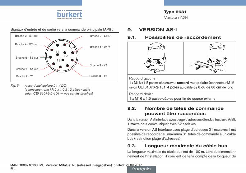
64
VersionAS-i
Type 8681
Signaux d’entrée et de sortie vers la commande principale (API) :
Broche 9 - Y3
Broche 8 - Y2
12
Broche 6 - S4 out
Broche 7 - Y1
Broche 1 - 24 V
Broche 5 - S3 out
Broche 4 - S2 out
11
Broche 3 - S1 out Broche 2 - GND
10
Fig. 5: raccord multipolaire 24 V DC (connecteur rond M12 x 1,0 à 12 pôles - mâle selon CEI 61076-2-101 — vue sur les broches)
9. VERSIONAS-I
9.1. Possibilitésderaccordement
Raccord gauche : 1 x M16 x 1,5 passe-câbles avec raccordmultipolaire (connecteur M12 selon CEI 61076-2-101, 4pôles au câble de 8oude80cm de long
Raccord droit : 1 x M16 x 1,5 passe-câbles pour fin de course externe
9.2. Nombredetêtesdecommandepouvantêtreraccordées
Dans la version AS Interface avec plage d’adresses étendue (esclave A/B), 1 maître peut communiquer avec 62 esclaves.
Dans la version AS Interface avec plage d’adresses 31 esclaves il est possible de raccorder au maximum 31 têtes de commande à un câble bus (restriction plage d’adresses).
9.3. LongueurmaximaleducâblebusLa longueur maximale du câble bus est de 100 m. Lors du dimension-nement de l’installation, il convient de tenir compte de la longueur du
français
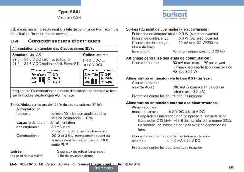
65
VersionAS-i
Type 8681
câble rond menant directement à la tête de commande (voir l’exemple de calcul en l’instructions de service).
9.4. Caractéristiquesélectriques
Alimentationentensiondesélectrovannes(EV):
Standard:via l‘AS-i 29,5 ... 31,6 V DC selon spécification 21,0 ... 31,6 V DC (selon spécif. Power24)
Option:externe
(19,2 V DC ... 31,6 V DC)
Réglage de l’alimentation en tension des vannes par descavaliers sur le module électronique AS Interface
Entrée/détecteurdeproximité(findecourseexterne:S4in): Alimentation en
tension : tension AS Interface appliquée à la tête de commande - 10 % Capacité de courant de l‘alimentation des capteurs : 30 mA maxi, Protection contre les courts-circuits Construction : DC 2 et 3 fils, normalement ouvert ou normalement fermé (par défaut : NO), sortie PNP
Entrée: 3 signaux de retour binaires et (du point de vue maître) 1 fin de course externe
Sorties(dupointdevuemaître)/électrovannes: Puissance de coupure maxi : 0,9 W (par électrovanne) Puissance continue typ. : 0,6 W (par électrovanne) Courant de démarrage : 30 mA resp. 0,9 W/200 ms Mode de fonc- tionnement Fonctionnement continu (100 %)
Affichage centralisé des états de commutation : Courant absorbé : 33 mA maxi resp. 1 W par voyant lumineux représenté (pour une tension AS-i de 30,5 V)
Alimentation en tension via le bus AS Interface : Courant absorbé maxi de AS-i : 200 mA (y compris fin de course externe avec 30 mA) Protection contre les courts-circuits intégrée
Alimentation en tension externe des électrovannes: Alimentation en tension externe : 19,2 V DC à 31,6 V DC L’appareil d’alimentation doit comprendre une séparation
fiable selon CEI 364-4-41. Il doit satisfaire à la norme SELV. Le potentiel de masse ne doit pas avoir de connexion de terre.
Courant absorbé maxi de l‘alimentation en tension externe : ≤ 110 mA à 24 V DC
Protection contre les courts-circuits intégrée
français

66
VersionAS-i
Type 8681
9.5. Installationélectrique(AS-i)
AVERTISSEMENT !
Risqued’explosionenatmosphèreexplosible(zone2)!• voir la note DANGER au chapitre « 8.3 », page 62 !
Risquedechocélectrique!• Avant d’intervenir dans le système (sauf pour l’apprentissage
(Teach-In) en atmosphère non explosible), coupez la tension et empêchez toute remise sous tension par inadvertance !
• Veuillez respecter les réglementations en vigueur pour les appareils électriques en matière de prévention des accidents ainsi qu’en matière de sécurité !
Risquedeblessuresdûàunmontagenonconforme!• Le montage doit être effectué uniquement par un personnel quali-
fié et habilité disposant de l’outillage approprié !
Les versions d’AS Interface avec raccord multipolaire sur le câble ne nécessitent pas de travaux de câblage internes. Vous avez cependant besoin des jeux de câbles confectionnés resp. montés avec les affec-tations des broches suivantes.
Broche 2
Broche 3 Broche 1
Broche 4
Fig. 6: raccord multipolaire AS-i
De même, le cavalier peut être réglé sur le module électronique AS-i conforme l‘alimentation en tension des électrovannes (EV) (via l‘AS-i ou externe) - voir figure à la page 65 .
alimentationentensiondesEV
Broche
(viaAS-i)
Affectation
(externe)
Affectation
Couleurdufil
1 AS-i+ AS-i+ brun
2 non affecté GND blanc
3 AS-i- AS-i- bleu
4 non affecté 24 V+ noir
Un findecourseexternepeut être raccordé au moyen de la petite borne plate triple (voir les instructions de service, chapitre «Raccor-dement d’un fin de course externe»).
français

67
VersionDeviceNet
Type 8681
10. VERSIONDEVICENET
10.1. Possibilitéderaccordement
Raccord gauche : 1 x M16 x 1,5 passe-câbles avec raccordmultipolaire (connecteur M12 selon CEI 61076-2-101, 5pôles) au câble de 80cm de long
Raccord droit : 1 x M16 x 1,5 passe-câbles pour fin de course externe
10.2. SpécificationDeviceNetFichierEDS 8681.EDS
Icônes 8681.ICO
Vitessedetransmission réglage usine : 125 kBit/s
Adresse réglage usine : 63
Donnéesprocess 2 ensembles d’entrées statiques (Entrée : de la tête de commande vers le maître/scanner DeviceNet) 1 ensemble de sorties statiques
Entrées 3 signaux de retour discrets du système de mesure de déplacement (positions S1 - S3) 1 signal de retour discret du fin de course externe (S4) 1 signal de déplacement analogique en mm
Alimentation par le faisceau DeviceNet (11 ... 25 V DC) Niveau de commutation signal High ≥ 5 V Niveau de commutation signal Low ≤ 1,5 V
Sorties 3 électrovannes
Puissanceabsorbéedubus puissance maxi 5 W, si toutes les vannes sont
activées (3 x type 6524 avec 0,6 W chaque)
10.3. LongueurtotaledecâbleLa longueur maximale totale des lignes (somme des lignes prin-cipales et des lignes de branchement) d’un réseau dépend de la vitesse de transmission.
La longueurmaximaletotaledeslignes (selon la spécification DeviceNet) est :
Vitessedetransmission
Groscâble(ThickCable)
Câblefin(ThinCable)
125 500 m 100 m250 250 m 100 m500 100 m 100 m
La longueurmaximaletotaleleslignesdebranchement (Drop Line) est :
Vitessedetransmission
Lignesdebranchement
Lasomme(duréseau)
125 6 m 156 m250 6 m 78 m500 6 m 39 m
français

68
VersionDeviceNet
Type 8681
10.4. CaractéristiquesélectriquesAlimentationentension: 11 ... 25 V DC (selon spécifica- tion)
Courantabsorbémaxi: 200 mA à 24 V DC
Entrée/détecteurdeproximité(findecourseexterne:S4in): Alimentation en tension : par alimentation en tension
DeviceNet - 10 % Capacité de courant de l’alimentation des capteurs : 30 mA maxi Protection contre les courts-circuits Construction : DC 2 et 3 fils, contact de fermeture (NO), sortie PNP Courant d’entrée signal 1 : Icapteur > 6,5 mA, limité en interne à 10 mA Tension d’entrée signal 1 : Ucapteur> 10 V Courant d’entrée signal 0 : Icapteur < 4 mA Tension d’entrée signal 0 : Ucapteur< 5 V
Entrées(dupointdevuemaître)/signauxderetourbinairesresp.analogiques : L’obtention des 3 positions de vanne signalées en binaire resp. du signal de déplacement analogique est décrite au chapitre «Système de mesure de déplacement» .
Sorties(dupointdevuemaître)/électrovannes: Puissance de coupure maxi : 1,0 W (par électrovanne) Puissance continue typ. : 0,6 W (par électrovanne) Réduction de la puissance : intégrée dans l’électronique de l’AS interface
Courant de démarrage : 120 mA typ. / 200 ms (3 vannes) Courant d’arrêt : 100 mA typ. à 24 V DC (3 vannes) Mode de fonc- tionnement : Fonctionnement continu (100 %)
Affichagecentralisédesétatsdecommutation: Courant absorbé depuis DeviceNet avec 24 V DC : 42 mA avec alimentation en tension 24 V DC par voyant lumineux représenté
10.5. Installationélectrique(DVN)
AVERTISSEMENT !
Risqued’explosionenatmosphèreexplosible(zone2)!• voir la note DANGER au chapitre « 8.3 », page 62 !
Risquedechocélectrique!• Avant d’intervenir dans le système (sauf pour l’apprentissage
(Teach-In) en atmosphère non explosible), coupez la tension et empêchez toute remise sous tension par inadvertance !
• Veuillez respecter les réglementations en vigueur pour les appareils électriques en matière de prévention des accidents ainsi qu’en matière de sécurité !
• Risquedeblessuresdûàunmontagenonconforme!• Le montage doit être effectué uniquement par un personnel quali-
fié et habilité disposant de l’outillage approprié !
français
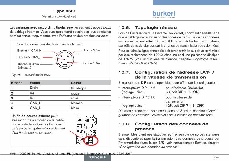
69
VersionDeviceNet
Type 8681
Les variantesavecraccordmultipolaire ne nécessitent pas de travaux de câblage internes. Vous avez cependant besoin des jeux de câbles confectionnés resp. montés avec l’affectation des broches suivante :
Broche 4: CAN_H
Broche 5: CAN_L
Broche 1: Drain (blindage)
Broche 3: V–
Broche 2: V+
Vue du connecteur de devant sur les fiches :
Fig. 7: raccord multipolaire
Broche Signal Coleur1 Drain (blindage)
2 V+ rouge3 V- noire4 CAN_H blanche5 CAN_L bleue
Un findecourseexterne peut être raccordé au moyen de la petite borne plate triple (voir Instructions de Service, chapitre «Raccordement d’un fin de course externe»).
10.6. TopologieréseauLors de l’installation d’un système DeviceNet, il convient de veiller à ce que le câblage de terminaison des lignes de transmission des données soit correctement effectué. Le câblage empêche les perturbations par réflexions de signaux sur les lignes de transmission des données.
Pour ce faire, la ligne principale doit être terminée aux deux extrémités par des résistances de 120 Ω chacune et d’une puissance dissipée de 1/4 W (voir Instructions de Service, chapitre «Topologie réseau d’un système DeviceNet»).
10.7. Configurationdel’adresseDVN/delavitessedetransmission
8 interrupteurs DIP sont disponibles pour effectuer la configuration :
• Interrupteurs DIP 1 à 6 pour l’adresse DeviceNet (réglage usine : 63, soit DIP 1 - 6: ON)
• Interrupteurs DIP 7 à 8 pour la vitesse de transmission (réglage usine : 125, soit DIP 7 + 8: OFF)
D’autres paramètres - voir Instructions de Service, chapitre «Confi-guration de l’adresse DeviceNet / de la vitesse de transmission».
10.8. Configurationdesdonnéesdeprocess
2 ensembles d’entrées statiques et 1 ensemble de sorties statiques sont disponibles pour la transmission des données de process par l’intermédiaire d’une liaison E/S - voir Instructions de Service, chapitre «Configuration des données de process».
français

70
VersionDeviceNet
Type 8681
«Adresse» dans le tableau c’est l’adresse attribut de données des ensembles pour l’accès en lecture: Class, Instance, Attribute.
Nom Adresse Formatdel’attributdedonnéesValeur0:OFF/Valeur1:ON
S1…S4
(réglage usine)
4, 1, 3 Octet0:Bit 0 : position S1 Bit 1 : position S2 Bit 2 : position S3 Bit 3 : position S4
S1…S4 + POS
(avec POS : position effective)
4, 2, 3 Octet0:Bit 0 : position S1 Bit 1 : position S2 Bit 2 : position S3 Bit 3 : position S4 Bits 4…7 : non utilisés
Octet1:POS in mm
«Adresse» dans le tableau c’est l’adresse attribut de données des ensembles pour l’accès en lecture: Class, Instance, Attribute.
Nom Adresse Formatdel’attributdedonnéesValeur0:OFF/Valeur1:ON
Electrovannes (EV) 1 ... 3
4, 21, 3 Octet0:Bit 0 : EV1 Bit 1 : EV2 Bit 2 : EV3 Bits 3…7 : non utilisés
10.9. Positiondesécuritédesélectrovannesencasdedéfautbus
En cas de panne du bus, l’électrovanne passe dans une position de sécurité programmable (par défaut : électrovanne sans courant) - données de configuration, voir Instructions de Service, chapitre «Configuration de l’appareil».
La LED d’état du bus «Network» (réseau) sur le module électronique donne les informations détaillées à travers la couleur et des séquence de clignotement sur le type d’erreur - voir Instructions de Service, chapitre «Affichage des LED d’état en cas de défaut bus».
français
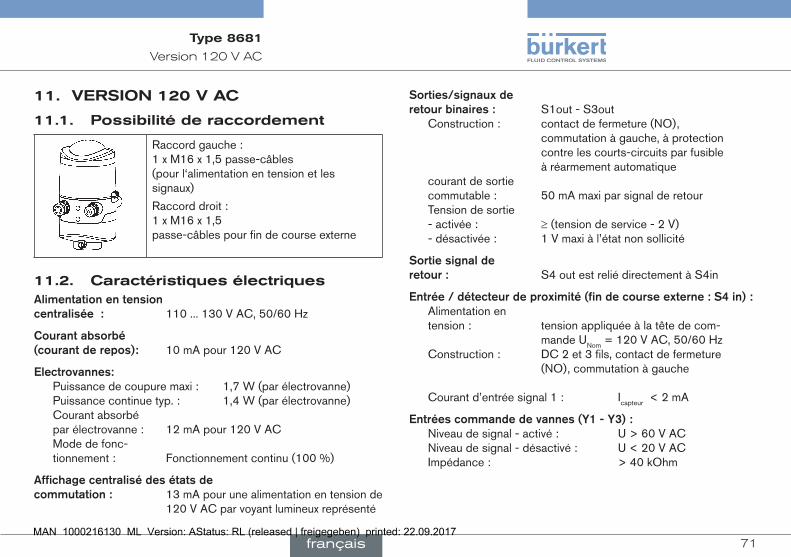
71
Version120VAC
Type 8681
11. VERSION120VAC
11.1. Possibilitéderaccordement
Raccord gauche : 1 x M16 x 1,5 passe-câbles (pour l‘alimentation en tension et les signaux)
Raccord droit : 1 x M16 x 1,5 passe-câbles pour fin de course externe
11.2. CaractéristiquesélectriquesAlimentationentensioncentralisée: 110 ... 130 V AC, 50/60 Hz
Courantabsorbé(courantderepos): 10 mA pour 120 V AC
Electrovannes: Puissance de coupure maxi : 1,7 W (par électrovanne) Puissance continue typ. : 1,4 W (par électrovanne) Courant absorbé par électrovanne : 12 mA pour 120 V AC Mode de fonc- tionnement : Fonctionnement continu (100 %)
Affichagecentralisédesétatsdecommutation: 13 mA pour une alimentation en tension de
120 V AC par voyant lumineux représenté
Sorties/signauxderetourbinaires: S1out - S3out Construction : contact de fermeture (NO),
commutation à gauche, à protection contre les courts-circuits par fusible à réarmement automatique courant de sortie commutable : 50 mA maxi par signal de retour Tension de sortie - activée : ≥ (tension de service - 2 V) - désactivée : 1 V maxi à l’état non sollicité
Sortiesignalderetour: S4 out est relié directement à S4in
Entrée/détecteurdeproximité(findecourseexterne:S4in): Alimentation en
tension : tension appliquée à la tête de com- mande UNom = 120 V AC, 50/60 Hz Construction : DC 2 et 3 fils, contact de fermeture (NO), commutation à gauche Courant d’entrée signal 1 : Icapteur < 2 mA
Entréescommandedevannes(Y1-Y3): Niveau de signal - activé : U > 60 V AC Niveau de signal - désactivé : U < 20 V AC Impédance : > 40 kOhm
français

72
Version120VAC
Type 8681
11.3. Installationélectrique(120V)
AVERTISSEMENT !
Risqued’explosionenatmosphèreexplosible(zone2)!• voir la note DANGER au chapitre « 8.3 », page 62 !
Risquedechocélectrique(120VAC)!• Ne touchez pas aux composants sous tension pendant le
réglage du système de mesure de déplacement (Teach-In) !• Avant d’intervenir dans le système (sauf pour l’apprentissage
(Teach-In) en atmosphère non explosible), coupez la tension et empêchez toute remise sous tension par inadvertance !
• Veuillez respecter les réglementations en vigueur pour les appareils électriques en matière de prévention des accidents ainsi qu’en matière de sécurité !
Risquedeblessuresdûàunmontagenonconforme!• La terre de protectionPEdoit être raccordée !• Le montage doit être effectué uniquement par un personnel qualifié
et habilité disposant de l’outillage approprié !
Cablegland:
Raccordement:Passe-câbles
→ Ouvrir le boîtier.
→ Confectionner les câbles de raccordement pour les signaux et l’alimentation en tension ainsi que, éventuellement, pour le fin de course externe conformément aux règles de la technique.
→ Introduire les câbles à l’intérieur du boîtier en passant par les passe-câbles correspondants.
→ Fixer les fils aux bornes de raccordement conformément aux affecta-tions de raccordement décrites dans la figure (regardez à la « Fig. 8 »).
Raccorde-ment d’él.-vanne avec LED d’état
pour vanne 1
Borne plate 1
interface de service
Interrupteur DIP pour codage coleur des LED
Borne plate 2 (fin de course externe)
Touches Teach-In T2, T3, T1Raccordements d’él.-vannes avec LED d’état pour vannes 2+3
Fig. 8: Module électronique (120 V AC)
Borneplate1 Affectation
PE Conducteur de protection (Protect. Earth)
L Alimentation en tension 120 V AC
Conducteur
N Conducteur neutre
S1 OUT Sortie position 1
S2 OUT Sortie position 2
S3 OUT Sortie position 3
S4 OUT Sortie fin de course externe
français
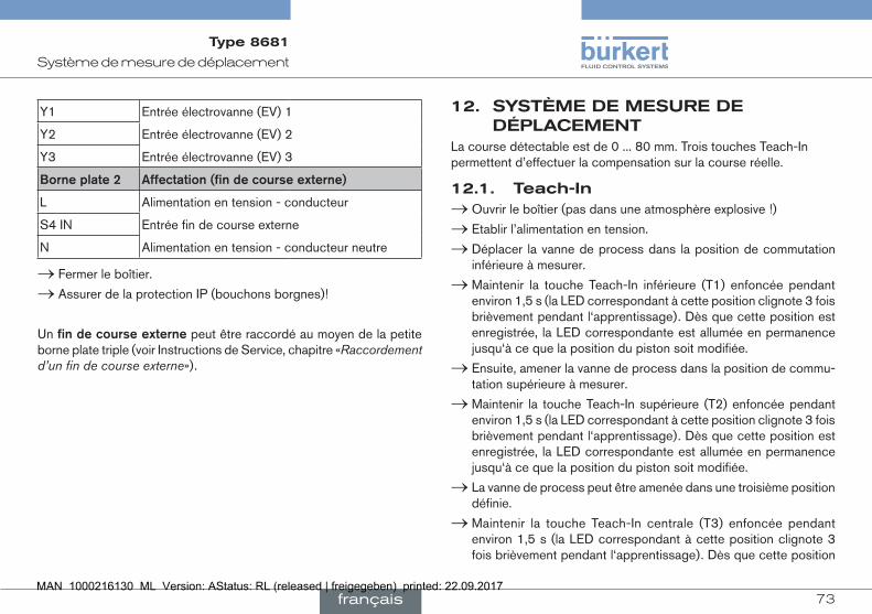
73
Systèmedemesurededéplacement
Type 8681
Y1 Entrée électrovanne (EV) 1
Y2 Entrée électrovanne (EV) 2
Y3 Entrée électrovanne (EV) 3
Borneplate2 Affectation(findecourseexterne)
L Alimentation en tension - conducteur
S4 IN Entrée fin de course externe
N Alimentation en tension - conducteur neutre
→ Fermer le boîtier.
→ Assurer de la protection IP (bouchons borgnes)!
Un findecourseexterne peut être raccordé au moyen de la petite borne plate triple (voir Instructions de Service, chapitre «Raccordement d’un fin de course externe»).
12. SYSTÈMEDEMESUREDEDÉPLACEMENT
La course détectable est de 0 ... 80 mm. Trois touches Teach-In permettent d’effectuer la compensation sur la course réelle.
12.1. Teach-In → Ouvrir le boîtier (pas dans une atmosphère explosive !)
→ Etablir l’alimentation en tension.
→ Déplacer la vanne de process dans la position de commutation inférieure à mesurer.
→ Maintenir la touche Teach-In inférieure (T1) enfoncée pendant environ 1,5 s (la LED correspondant à cette position clignote 3 fois brièvement pendant l‘apprentissage). Dès que cette position est enregistrée, la LED correspondante est allumée en permanence jusqu‘à ce que la position du piston soit modifiée.
→ Ensuite, amener la vanne de process dans la position de commu-tation supérieure à mesurer.
→ Maintenir la touche Teach-In supérieure (T2) enfoncée pendant environ 1,5 s (la LED correspondant à cette position clignote 3 fois brièvement pendant l‘apprentissage). Dès que cette position est enregistrée, la LED correspondante est allumée en permanence jusqu‘à ce que la position du piston soit modifiée.
→ La vanne de process peut être amenée dans une troisième position définie.
→ Maintenir la touche Teach-In centrale (T3) enfoncée pendant environ 1,5 s (la LED correspondant à cette position clignote 3 fois brièvement pendant l‘apprentissage). Dès que cette position
français

74
miseenservice
Type 8681
est enregistrée, la LED correspondante clignote en permanence jusqu‘à ce que la position du piston soit modifiée.
→ Le cas échéant, ramener la tête de commande et l’installation à l’état normal (position de commutation, alimentation en tension).
→ Fermer le boîtier.
12.2. Teach-Reset → Maintenir les touches Teach-In (T1+T2) enfoncée pendant environ 1,5 s (message de retour visuel : clignotement dans la couleur de défaut)
12.3. AutotuneLes fonctions autotune et déroulement de autotune - voir les instruc-tions de service.
12.4. AffectationdescouleursdesLEDS1 - vert, illumination permanent, S2 - jaune, illumination permanent, S3 - vert, clignotement permanent (250 ms/250 ms)
(Etat de livraison des interrupteurs DIP : 0000)
D‘autres combinaisons de couleurs peuvent être réglées à l‘aide des interrupteurs DIP - voir le manuel, chapitre « Réglagedescom-binaisonsdecouleurs ».
Les voyants clignotent en cas de défaut, avec différentes « séquences de clignotement » voir le manuel, chapitre « Séquencedecligno-tement,signalisationdedéfaut ».
Si différents messages doivent être envoyés simultanément, des priorités sont appliquées : voir le manuel, chapitre «Prioritésdessignaux».
13. MISEENSERVICE
AVERTISSEMENT !
Risquedeblessuresdûàunmontagenonconforme!
Une utilisation non conforme peut entraîner des blessures et endom-mager l’appareil et son environnement.• Avant la mise en service, il faut s’assurer que le contenu des
instructions de service est connu et parfaitement compris par les opérateurs.
• Respectez les consignes de sécurité et l’utilisation conforme.• L’appareil/l’installation doit être mis(e) en service uniquement par
un personnel suffisamment formé.
→ Montage de la tête de commande type 8681.
→ Installation pneumatique et électrique.
→ Réglage du système de mesure de déplacement (Teach-In).
Après le montage, l‘installation et le réglage du système de mesure selon les instructions de service la tête de commande est prête à l‘usage.
français

75
Emballage,Transport,Stockage,Elimination
Type 8681
14. EMBALLAGE,TRANSPORT,STOCKAGE,ELIMINATION
REMARQUE !
Dommagesdusautransportetstockage!
Les appareils insuffisamment protégés peuvent être endommagés pendant le transport ou stockage.• Transportez / stockez l’appareil à l’abri de l’humidité et des impu-
retés et dans un emballage résistant aux chocs. • Evitez les effets de la chaleur et du froid pouvant entraîner le
dépassement vers le haut ou le bas de la température de stockage admissible.
• Température de stockage : -20 ... +65 °C.
REMARQUE !
Dommagesàl’environnementcauséspardespiècesd’appareilcontaminéespardesfluides.• Respectez les prescriptions en matière d’élimination des déchets et
de protection de l’environnement en vigueur.
→ Eliminez l’appareil et l’emballage dans le respect de l’environnement.
→ Respectez les prescriptions nationales en matière d’élimination des déchets.
français

www.burkert.com