Quick•Point Clamping Studs · 2019-10-24 · This handle bar facilitates the handling of...
10
12 H6 6 22 26 M8 0,7x45° 16 H6 6 22 28 M10 0,7x45° 15 9 12 H6 6 8,6 0,7x45° 17,5 11 16 H6 6 12,6 0,7x45° 50 ZERO-POINT CLAMPING SYSTEM QUICK•POINT ® ACCESSORIES Quick•Point ® Clamping Studs For individual adaptation of fixtures, workpieces or existing vices onto our Quick•Point ® zero-point clamping system. with threaded pins with screws 52 52 96 96 How it works: QUICK•POINT ® CLAMPING STUDS FOR INDIVIDUAL ADAPTATION ITEM NO. DESCRIPTION UNIT PRICE 45270 Ø 16 mm for 52 mm spacing, incl. M 8 threaded pin 1 pc. 45570 Ø 20 mm for 96 mm spacing, incl. M 10 threaded pin 1 pc. Please note: 4 Clamping Studs are required for one Quick•Point ® plate!
Transcript of Quick•Point Clamping Studs · 2019-10-24 · This handle bar facilitates the handling of...
12 H6 6
22
26
M8
0,7
x45°
16 H6
6
22
28
M10
0,7
x45°
15 9
12 H6
6
8,6
0
,7x4
5°
17,5 11
16 H6
6
12,
6 0
,7x4
5°
50
ZERO-POINT CLAMPING SYSTEM QUICK•POINT® ACCESSORIES
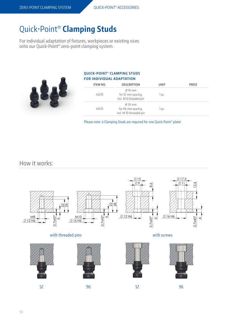
Quick•Point® Clamping StudsFor individual adaptation of fixtures, workpieces or existing vices onto our Quick•Point® zero-point clamping system.
with threaded pins with screws
52 5296 96
How it works:
Q U I C K • P O I N T ® C L A M P I N G S T U D S F O R I N D I V I D U A L A DA P TAT I O N
ITEM NO. DESCRIPTION UNIT PRICE
45270Ø 16 mm
for 52 mm spacing, incl. M 8 threaded pin
1 pc.
45570Ø 20 mm
for 96 mm spacing, incl. M 10 threaded pin
1 pc.
Please note: 4 Clamping Studs are required for one Quick•Point® plate!
12 H6 6
22
26
M8
0,7
x45°
16 H6
6
22
28
M10
0,7
x45°
15 9
12 H6
6
8,6
0
,7x4
5°
17,5 11
16 H6
6
12,
6 0
,7x4
5°
51
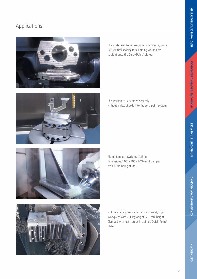
The studs need to be positioned in a 52 mm / 96 mm (± 0.01 mm) spacing for clamping workpieces straight onto the Quick•Point® plates.
Aluminium part (weight: 1.315 kg, dimensions: 1.067 × 406 × 1.016 mm) clamped with 16 clamping studs.
Not only highly precise but also extremely rigid: Workpiece with 200 kg weight, 500 mm height. Clamped with just 4 studs in a single Quick•Point® plate.
The workpiece is clamped securely, without a vice, directly into the zero-point system.
Applications:
CLEA
NIN
G F
AN
CON
VEN
TIO
NA
L W
OR
KH
OLD
ING
MA
KR
O•G
RIP
® 5
-AX
IS V
ICES
MA
KR
O•G
RIP
® S
TAM
PIN
G T
ECH
NO
LOGY
ZER
O-P
OIN
T CL
AM
PIN
G S
YST
EM
52
ZERO-POINT CLAMPING SYSTEM QUICK•POINT® ACCESSORIES
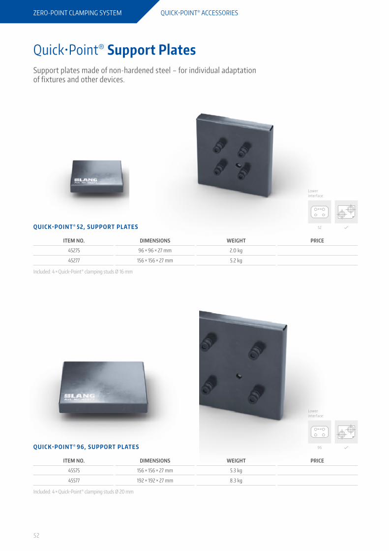
Quick•Point® Support PlatesSupport plates made of non-hardened steel – for individual adaptation of fixtures and other devices.
Lower interface:
Lower interface:
Q U I C K • P O I N T ® 5 2 , S U P P O R T P L AT E S
ITEM NO. DIMENSIONS WEIGHT PRICE
45275 96 × 96 × 27 mm 2.0 kg
45277 156 × 156 × 27 mm 5.2 kg
Included: 4 × Quick•Point® clamping studs Ø 16 mm
Q U I C K • P O I N T ® 9 6 , S U P P O R T P L AT E S
ITEM NO. DIMENSIONS WEIGHT PRICE
45575 156 × 156 × 27 mm 5.3 kg
45577 192 × 192 × 27 mm 8.3 kg
Included: 4 × Quick•Point® clamping studs Ø 20 mm
52
96
53
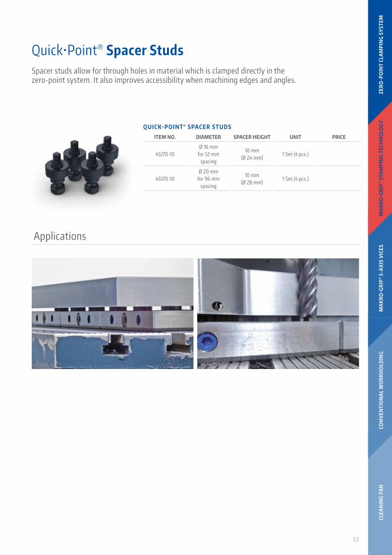
Quick•Point® Spacer StudsSpacer studs allow for through holes in material which is clamped directly in the zero-point system. It also improves accessibility when machining edges and angles.
Applications
Q U I C K • P O I N T ® S PAC E R S T U D S
ITEM NO. DIAMETER SPACER HEIGHT UNIT PRICE
45270-10Ø 16 mm
for 52 mm spacing
10 mm (Ø 24 mm)
1 Set (4 pcs.)
45570-10Ø 20 mm
for 96 mm spacing
10 mm (Ø 28 mm)
1 Set (4 pcs.)
CLEA
NIN
G F
AN
CON
VEN
TIO
NA
L W
OR
KH
OLD
ING
MA
KR
O•G
RIP
® 5
-AX
IS V
ICES
MA
KR
O•G
RIP
® S
TAM
PIN
G T
ECH
NO
LOGY
ZER
O-P
OIN
T CL
AM
PIN
G S
YST
EM

70°
54
ZERO-POINT CLAMPING SYSTEM QUICK•POINT® ACCESSORIES
Quick•Point® Quick-Lock Fast Actuation SystemMechanical and quick fastener, compatible with all rectangular and squared Quick•Point® plates. Also compatible with the Quick•Point® 96, 2-fold Grid Plate, round. With the Quick-Lock, we provide a clamping lever and washers to adjust clamping force as needed.
Q U I C K • P O I N T ® Q U I C K- LO C K 5 2
ITEM NO. DESCRIPTION FOR ITEM NO. WEIGHT PRICE
44552Quick-Lock for Quick•Point® 52 Single-
Plates, Twin Base 52, Adaptor Plate, 5-Axis Riser 52
45600 / 75600 / 45150 / 45151 / 47220 / 45160 / 45156 / 45157
0.3 kg
45252 Quick-Lock for Quick•Point® 52, 2-fold
Grid Plate45621 0.8 kg
45452Quick-Lock for Quick•Point® 52, 4-fold
Grid Plate45640 / 45641 0.9 kg
Q U I C K • P O I N T ® Q U I C K- LO C K 9 6
ITEM NO. DESCRIPTION FOR ITEM NO. WEIGHT PRICE
44596Quick-Lock for Quick•Point® 96 Single-
Plates, Twin Base 96, Adaptor Plate, 5-Axis Riser 96
45710 / 45763 / 45715 / 45716 / 45400 / 45401 / 47520 / 45406 / 45407
0.4 kg
45296Quick-Lock for Quick•Point® 96, 2-fold
Grid Plate45720 0.9 kg
45996 Quick-Lock for Quick•Point® 96, 2-fold
Grid Plates, round45962 / 45963 / 45964 0.9 kg
45496Quick-Lock for Quick•Point® 96, 4-fold
Grid Plates45740 / 45741 / 45742 1.0 kg

70°
55
Easy assembly in a few steps
Within just a few seconds the Quick-Lock fast actuation system is mounted to a Quick•Point® Plate. With a 180° motion of the lever the Quick-Lock clamps and releases the vice.
Quick-Lock utilisation
The clamping lever equipped with a rotation lock can be used both horizontally and vertically. For vices and fixtures protruding from the Quick•Point® plate, the lever is used horizontally (right picture).
Removal of the Quick•Point® actuation screw:Remove actuation screw and the two plastic covers and keep them safe. With multi fold plates you also have to remove the actuation bolt. During the whole installation process the Quick•Point® plate does not have to be removed from the machine table if already mounted.
Installation of the Quick-Lock fastener:Insert the Quick-Lock pressure bolt into the actuation screw channel and tighten the two screws.
Checking the clamping forces:Insert the clamping lever into the clamping element of the Quick-Lock fastener. Move the clamping lever in a 180° motion from right to left until you feel resistance. If the remaining angle is more/less than 70°, the clamping force needs to be adjusted by adding/removing washers.Detailed instructions and videos can be found on our website www.lang-technik.de.
CLEA
NIN
G F
AN
CON
VEN
TIO
NA
L W
OR
KH
OLD
ING
MA
KR
O•G
RIP
® 5
-AX
IS V
ICES
MA
KR
O•G
RIP
® S
TAM
PIN
G T
ECH
NO
LOGY
ZER
O-P
OIN
T CL
AM
PIN
G S
YST
EM

56
ZERO-POINT CLAMPING SYSTEM QUICK•POINT® ACCESSORIES
Quick•Point® Accessories
Q U I C K • P O I N T ® COV E R P LU G S , P L A S T I C
ITEM NO. DIAMETER UNIT PRICE
45052-20Ø 16 mm for 52 mm
spacing1 set (4 pcs.)
45096-20Ø 20 mm for 96 mm
spacing1 set (4 pcs.)
Cover plugs made of plastic for the protection of the stud holes when not in use. For multi fold plates steel plugs (see below) are necessary.
Q U I C K • P O I N T ® COV E R D I S C S , P L A S T I C
ITEM NO. DIAMETER UNIT PRICE
45008-15 Ø 15 mm 1 set (20 pcs.)
45008-20 Ø 20 mm 1 set (20 pcs.)
45008-27 Ø 27 mm 1 set (20 pcs.)
Heat-resistant, fibreglass reinforced cover discs for protecting the mounting screws against material pollution.
Q U I C K • P O I N T ® COV E R P LU G S , S T E E L
ITEM NO. DIAMETER UNIT PRICE
45052-30Ø 16 mm for 52 mm
spacing1 set (4 pcs.)
45096-30Ø 20 mm for 96 mm
spacing1 set (4 pcs.)
Cover plugs made of steel spread the increased clamping force of multi grid plates evenly and protect stud holes not in use. They can be removed from plates with the Cover Plug Remover.
Q U I C K • P O I N T ® COV E R P LU G R E M OV E R
ITEM NO. DESCRIPTION PRICE
45000-30 Cover Plug Remover
Comfortable grip with magnet for removing steel plugs from the Quick•Point® plates.
Q U I C K • P O I N T ® H A N D L E B A R , A LU M I N I U M
ITEM NO. DESCRIPTION PRICE
46081 Handle Bar
This handle bar facilitates the handling of Quick•Point® devices when setting up and dismantling. As with usual LANG clamping devices, the handle bar is clamped with two Quick•Point® 96 clamping studs in the zero-point system and is thereby especially suited for the transportation of heavier Quick•Point® products.

57
Quick•Point® Alignment Accessories
S LOT K E YS , LO O S E , D I N 6 3 2 3 , F O R A X I A L A L I G N M E N T O F Q U I C K • P O I N T ® P L AT E S
ITEM NO. SIZE UNIT PRICE
452014 20 to 14 mm 1 pc.
452018 20 to 18 mm 1 pc.
To make the assembly and alignment of the Quick•Point® plates as easy as possible, we offer slot keys for the plates’ 20H7 keyways matching your table’s t-slots (14 or 18 mm).Attention: Keys not suitable for Item No. 45800 and 45890!
S LOT K E YS F O R A X I A L A L I G N M E N T O F Q U I C K • P O I N T ® R O U N D P L AT E , I T E M N O. 4 5 8 9 0 (PAG E 2 5)
ITEM NO. DIMENSIONS UNIT PRICE
452214 14 × 22 mm 1 pc.
452218 18 × 22 mm 1 pc.
For the alignment of Quick•Point® plate, Item No. 45890, which has 14 & 18 H7 grooves in the bottom, we offer these keys. Grooves and keys are equipped with a M6 thread, suitable for screws DIN 84 or DIN 912, M6 × 16.
C E N T R I N G S T U D S F O R CO N C E N T R I C A L I G N M E N T O F Q U I C K • P O I N T ® P L AT E S
ITEM NO. SIZE UNIT PRICE
451230 12 to 30 mm 1 pc.
451232 12 to 32 mm 1 pc.
451250 12 to 50 mm 1 pc.
452530 25 to 30 mm 1 pc.
452532 25 to 32 mm 1 pc.
452550 25 to 50 mm 1 pc.
455030 50 to 30 mm 1 pc.
455032 50 to 32 mm 1 pc.
455050 50 to 50 mm 1 pc.
For the concentric alignment of Quick•Point® plates via fitting bores in the bottom (12, 25, 50 mm) we offer centring studs for the most common machine table holes (30, 32, 50 mm).
B U S H I N G S F O R T H E A L I G N M E N T O F V I C E S A N D Z E R O - P O I N T P L AT E S
ITEM NO. DIMENSIONS FOR SCREW SIZE UNIT PRICE
45000-09 Ø 12 × 12 mm M 10 1 pc.
65191-04 Ø 12 × 12 mm M 8 1 pc.
65191-05 Ø 16 × 15 mm M 10 1 pc.
Item No. 45000-09 is suitable for aligning Quick•Point® plates on aluminum risers, Quick•Tower tombstones and other, select applications. Bushings 65191-04 and 65191-05 are used for the alignment and mounting of Makro•Grip® 5-Axis Vices on (old) LANG automation support pallets Item No. 65190 and 65197.
CLEA
NIN
G F
AN
CON
VEN
TIO
NA
L W
OR
KH
OLD
ING
MA
KR
O•G
RIP
® 5
-AX
IS V
ICES
MA
KR
O•G
RIP
® S
TAM
PIN
G T
ECH
NO
LOGY
ZER
O-P
OIN
T CL
AM
PIN
G S
YST
EM

96
96
60
0,01 A0,01
0,01 A0,01
30 56
20 H6
52
0,005 A
A
96
96
60
0,01 A0,01
0,01 A0,01
30 56
20 H6
52
0,005 A
A
96 3
0 56
20 H6 0,005 A
A
60
126
126
0,01 A0,01
0,01 A0,01
96
30 5
6
20 H6 0,005 A
A
60
126
126
0,01 A0,01
0,01 A0,01
346
122
20
0 4848144
0
48
144
48
192
90
20
0 78262678
0
26
26
58
ZERO-POINT CLAMPING SYSTEM ALIGNMENT AND MOUNTING OPTIONS
Quick•Point® Gauging Pallet
Jig-ground gauging pallet for a quick and precise alignment of Quick•Point® plates. Recommended especially for rotary tables or chucks.
Quick∙Point® Gauging Pallet 52
Quick∙Point® Gauging Pallet 96
How it works:
After clamping the gauging pallet in a Quick•Point® plate, the axial alignment of the Quick•Point® plate is done by probing the jig-ground sides of the gauging pallet. For a concentric alignment the inner diameter of the gauging pallet can be used.
Watch the video for a complete instruction or download the manual from our website!
Q U I C K ∙ P O I N T ® G AU G I N G PA L L E T
ITEM NO. FOR DIMENSIONS MEASURING LENGTH WEIGHT PRICE
44252 Quick•Point® 52 96 × 96 × 56 mm 95 mm per side 2.6 kg
44296 Quick•Point® 96 126 × 126 × 56 mm 125 mm per side 4.2 kg
96
96
60
0,01 A0,01
0,01 A0,01
30 56
20 H6
52
0,005 A
A
96
96
60
0,01 A0,01
0,01 A0,01
30 56
20 H6
52
0,005 A
A
96
30 5
6
20 H6 0,005 A
A
60
126
126
0,01 A0,01
0,01 A0,01
96
30 5
6
20 H6 0,005 A
A
60
126
126
0,01 A0,01
0,01 A0,01
346 1
22
20
0 4848144
0
48
144
48
192
90
20
0 78262678
0
26
26
59
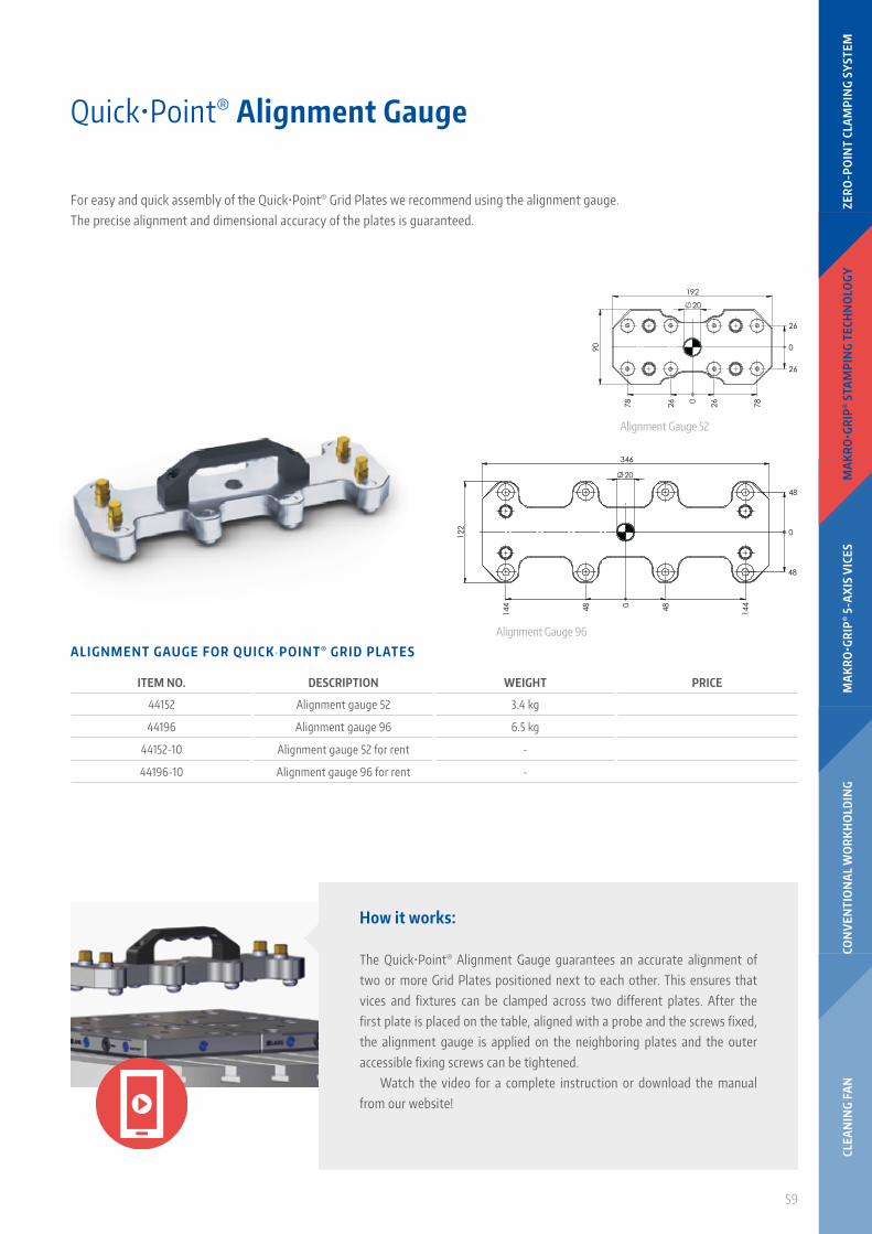
Quick•Point® Alignment Gauge
For easy and quick assembly of the Quick•Point® Grid Plates we recommend using the alignment gauge. The precise alignment and dimensional accuracy of the plates is guaranteed.
Alignment Gauge 52
Alignment Gauge 96
How it works:
The Quick•Point® Alignment Gauge guarantees an accurate alignment of two or more Grid Plates positioned next to each other. This ensures that vices and fixtures can be clamped across two different plates. After the first plate is placed on the table, aligned with a probe and the screws fixed, the alignment gauge is applied on the neighboring plates and the outer accessible fixing screws can be tightened.
Watch the video for a complete instruction or download the manual from our website!
A L I G N M E N T G AU G E F O R Q U I C K ∙ P O I N T ® G R I D P L AT E S
ITEM NO. DESCRIPTION WEIGHT PRICE
44152 Alignment gauge 52 3.4 kg
44196 Alignment gauge 96 6.5 kg
44152-10 Alignment gauge 52 for rent -
44196-10 Alignment gauge 96 for rent -
CLEA
NIN
G F
AN
CON
VEN
TIO
NA
L W
OR
KH
OLD
ING
MA
KR
O•G
RIP
® 5
-AX
IS V
ICES
MA
KR
O•G
RIP
® S
TAM
PIN
G T
ECH
NO
LOGY
ZER
O-P
OIN
T CL
AM
PIN
G S
YST
EM