Quick Start OrCAD PSpice 17 - FlowCAD · manual or as a complete operating manual. • Basic...
57
www.FlowCAD.com 1 FlowCAD Confidential Quick Start OrCAD PSpice 17.2 Roberto Gandía Blanquer
Transcript of Quick Start OrCAD PSpice 17 - FlowCAD · manual or as a complete operating manual. • Basic...
ww
w.F
low
CA
D.c
om
1
FlowCAD Confidential
Quick Start OrCAD PSpice 17.2
Roberto Gandía Blanquer
ww
w.F
low
CA
D.c
om
2
FlowCAD Confidential
Contents
• Introduction
• Basic handling in Capture / PSpice
• Types of Simulation
• Design Example: Switched Mode Power Supply (SMPS)
• Appendix: PSpice AD Extensions

ww
w.F
low
CA
D.c
om
3
FlowCAD Confidential
Preliminary Notes
• This documentation applies to the first-time users of the PSpice simulation software,
in particular the DEMO version. It should not be understood either as a training
manual or as a complete operating manual.
• Basic knowledge in electronic circuitry is required.
• Due to the brevity and compactness of this documentation, it is not possible to
address all existing functions and their acuteness. Please refer to Help PSpice
Documentation.
• After some preliminary information on the software, the instructions begin with the
circuit diagram. This circuit will be showed using the American and the European
symbols.
• Using a simple circuit diagram for a power supply, the most important functions and
steps are presented and explained with PSpice, which allows the first-time user to
gain a first impression with a minimum effort at the time of the initial training and,
if necessary, to cope with the first tasks.
• To get started, just start the DEMO version and unzip the PSpice_Demo.zip file to a
folder of your choice.

ww
w.F
low
CA
D.c
om
4
FlowCAD Confidential
Introduction
ww
w.F
low
CA
D.c
om
5
FlowCAD Confidential
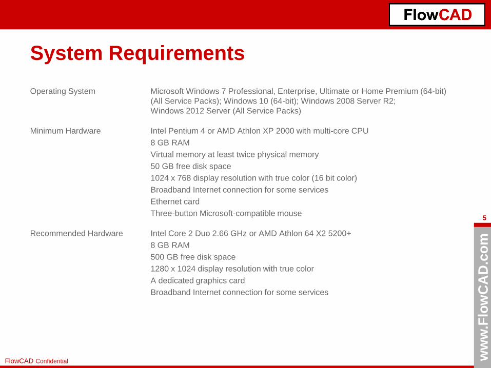
System Requirements
Operating System Microsoft Windows 7 Professional, Enterprise, Ultimate or Home Premium (64-bit)
(All Service Packs); Windows 10 (64-bit); Windows 2008 Server R2;
Windows 2012 Server (All Service Packs)
Minimum Hardware Intel Pentium 4 or AMD Athlon XP 2000 with multi-core CPU
8 GB RAM
Virtual memory at least twice physical memory
50 GB free disk space
1024 x 768 display resolution with true color (16 bit color)
Broadband Internet connection for some services
Ethernet card
Three-button Microsoft-compatible mouse
Recommended Hardware Intel Core 2 Duo 2.66 GHz or AMD Athlon 64 X2 5200+
8 GB RAM
500 GB free disk space
1280 x 1024 display resolution with true color
A dedicated graphics card
Broadband Internet connection for some services

ww
w.F
low
CA
D.c
om
6
FlowCAD Confidential
OrCAD Lite Limits
The free version is a fully functional design package including PSpice, which is limited only by the number of
components, component pins, network nodes and integration of additional simulation models.
You can design, simulate and create small circuits in the schematic, create your layout, and create output for your
production. This data can be stored.
Larger circuits and layouts can be viewed, but NOT stored.
In the current 17.2 version the following limits must be observed:
Capture
Maximal 60 parts and 75 nets, including the hierarchical blocks in the design, no part with more than 100 pins,
maximal 1.000 parts in the CIS Database, FPGA flow is not available, you cannot validate Electrical Csets,
Altium translator is not available.
PSpice
Maximal 75 nodes, 20 transistors, no sub-circuit limits but 65 digital primitive devices, and 10 transmission lines (ideal
or non-ideal) with not more than four pairwise coupled lines, Model Editor limited to diodes, all libraries are included,
you cannot use level 3 of Core model, MOSFET BSIM 3.2, or MOSFET BSIM 4, only simulation data created using the
Lite version of the simulator, only power transformers in Magnetic Parts Editor, maximal nodes in digital circuit 250,
non-ideal Tline is limited to 4, PSpice DMI models are not supported, IBIS import is not supported, PSpice SLPS flow is
not supported.
ww
w.F
low
CA
D.c
om
7
FlowCAD Confidential
Installation and Settings
• The demo version is included in the full version 17.2. If you have installed the 17.2 full
version, a demo version will automatically be switched over when no license server
has been installed.
• Inserting the DVD, the setup program will start automatically. If the Autorun function of
your computer is deactivated, use Windows Explorer to open the folder of the DVD
and start „setup.exe“.
• Start the product installation. Follow the instructions in the installation program. Do not
install license manager!
An installation guide can also be found in this DVD or at
http://www.flowcad.de/Application_Notes.htm (Quick Start PSpice 17.2 Lite).
OrCAD allows to use a variety of personal settings, from product configuration to design
templates to color selection of the design elements used.
These possibilities are not discussed here as they go beyond the purpose of this
documentation. It is only mentioned that many of these settings are stored in the
corresponding INI files.

ww
w.F
low
CA
D.c
om
8
FlowCAD Confidential
Basic Handling in Capture / PSpice
ww
w.F
low
CA
D.c
om
9
FlowCAD Confidential
Operating Concept
OrCAD Capture and OrCAD PSpice are basically menu driven.
It is highly recommended to use only underline as a special character in the path and
name of the design.
All inputs or commands are made by one of the following options:
• Pull-down menus
• Icons
• Shortcuts
• Pop-up window
• Command window
• TLC functions
In Capture and PSpice context-sensitive menus are used. This means that depending on
the selected elements, workspaces or commands, the resulting pop-up windows change,
or the pull-down menu changes its appearance (Capture).

ww
w.F
low
CA
D.c
om
10
FlowCAD Confidential
Main File Extensions in OrCAD (PSpice)
.OPJ OrCAD Capture Project File
.DSN OrCAD Capture Design File
.DBK Design Backup
.OLB Capture / PSpice Symbol Library
.UPD Property Update File
.DRC Design Rules Check
.BOM Bill of Materials File
.EXP Export Properties File
.LIB PSpice Model Library File
.DAT Probe Data File
.OUT PSpice Output File
.SIM Simulation Profile
.NET PSpice Netlist
.PRB Probe Configuration File
.STL Stimulus Library File
.CIR PSpice Circuit File
ww
w.F
low
CA
D.c
om
11
FlowCAD Confidential
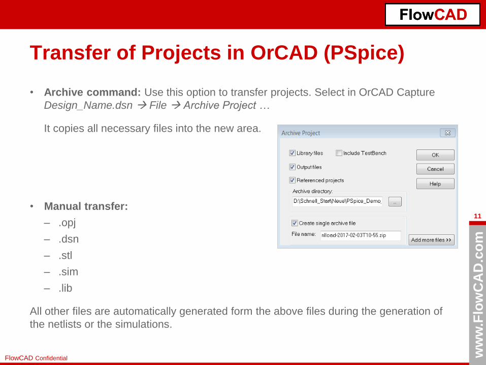
Transfer of Projects in OrCAD (PSpice)
• Archive command: Use this option to transfer projects. Select in OrCAD Capture
Design_Name.dsn File Archive Project …
It copies all necessary files into the new area.
• Manual transfer:
– .opj
– .dsn
– .stl
– .sim
– .lib
All other files are automatically generated form the above files during the generation of
the netlists or the simulations.
ww
w.F
low
CA
D.c
om
12
FlowCAD Confidential
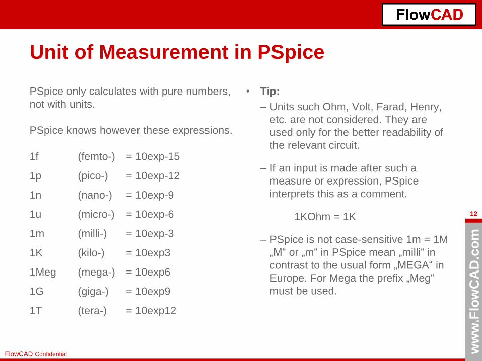
Unit of Measurement in PSpice
PSpice only calculates with pure numbers,
not with units.
PSpice knows however these expressions.
1f (femto-) = 10exp-15
1p (pico-) = 10exp-12
1n (nano-) = 10exp-9
1u (micro-) = 10exp-6
1m (milli-) = 10exp-3
1K (kilo-) = 10exp3
1Meg (mega-) = 10exp6
1G (giga-) = 10exp9
1T (tera-) = 10exp12
• Tip:
– Units such Ohm, Volt, Farad, Henry,
etc. are not considered. They are
used only for the better readability of
the relevant circuit.
– If an input is made after such a
measure or expression, PSpice
interprets this as a comment.
1KOhm = 1K
– PSpice is not case-sensitive 1m = 1M
„M“ or „m“ in PSpice mean „milli“ in
contrast to the usual form „MEGA“ in
Europe. For Mega the prefix „Meg“
must be used.

ww
w.F
low
CA
D.c
om
13
FlowCAD Confidential
Proposed Circuit (I)
• The aim of this PSpice introduction is to simulate a complete circuit, particularly
a Switched Mode Power Supply (SMPS), where a rectifier, a PWM Control and
a transformer are used. The illustrated circuit includes three additional areas (source,
filter and load) required to simulate the overall circuit.
• In the "Solution" directories, there is an example for simulating the overall circuit
shown. You will find the European solution. Default Cadence symbols are American
ones, that is why, you will use an external European symbol library for R, L and C
(Europe.olb).
• On the following pages, you will find a brief overview of the actions you can take to
implement the circuit diagram below.
Tip:
The correct definition of the mass potential must also be used. "0"
ww
w.F
low
CA
D.c
om
14
FlowCAD Confidential
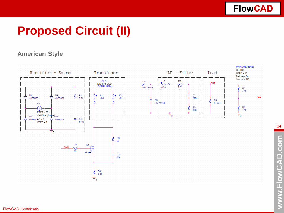
Proposed Circuit (II)
American Style

ww
w.F
low
CA
D.c
om
15
FlowCAD Confidential
Proposed Circuit (III)
European Style
ww
w.F
low
CA
D.c
om
16
FlowCAD Confidential
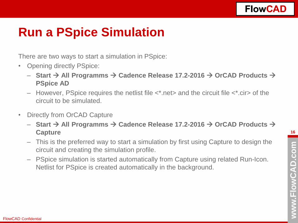
Run a PSpice Simulation
There are two ways to start a simulation in PSpice:
• Opening directly PSpice:
– Start All Programms Cadence Release 17.2-2016 OrCAD Products
PSpice AD
– However, PSpice requires the netlist file <*.net> and the circuit file <*.cir> of the
circuit to be simulated.
• Directly from OrCAD Capture
– Start All Programms Cadence Release 17.2-2016 OrCAD Products
Capture
– This is the preferred way to start a simulation by first using Capture to design the
circuit and creating the simulation profile.
– PSpice simulation is started automatically from Capture using related Run-Icon.
Netlist for PSpice is created automatically in the background.

ww
w.F
low
CA
D.c
om
17
FlowCAD Confidential
Capture Session Frame
All subsequent processes are
started from this session
frame window.
File New Project ...
creates a new project where
the design is defined.
The following menu appears.
NOTE: If you click on File
Open Demo Designs, you
will be able to open examples
with documentation.

ww
w.F
low
CA
D.c
om
18
FlowCAD Confidential
New PSpice Project
In the upper field under Name enter the name of your
project, e.g. SMPS.
As project type, select Analog or Mixed A/D as we want
to perform a simulation with this project.
In the lower field under Location, select the folder in
which your new project should be stored. It is highly
recommended to use the project name again as a folder
entry. As a result, all project data generated for this
simulation project are stored in this folder, which
considerably increases the overview.
Then we click OK.
NOTE: In the right side at the bottom you find an option
called “Learn with PSpice”. If you click on it, you will
open the Learning PSpice documentation.
Since we do not have a simulation project yet,
we are generating a completely new project.

ww
w.F
low
CA
D.c
om
19
FlowCAD Confidential
Project SMPS
Done!
A new project called SMPS with
a design of the same name
smps.dsn.
At the same time, the first page of
your design was opened with the
name PAGE1. Similarly, the
drawing frame and the head were
automatically placed. Other view-
presets are possible.
Please note the folder structure in
the project manager on the left
side of the image.
The folder structure is virtual.
It only exists within the project
manager. The PAGE1 located
under Schematic1 is only found
within the smps.dsn file.
The icons for component
placement and wiring are already
visible on the right-hand side.
ww
w.F
low
CA
D.c
om
20
FlowCAD Confidential
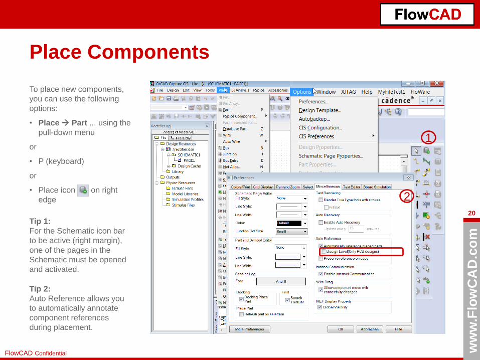
Place Components
To place new components,
you can use the following
options:
• Place Part ... using the
pull-down menu
or
• P (keyboard)
or
• Place icon on right
edge
Tip 1:
For the Schematic icon bar
to be active (right margin),
one of the pages in the
Schematic must be opened
and activated.
Tip 2:
Auto Reference allows you
to automatically annotate
component references
during placement.
1
2

ww
w.F
low
CA
D.c
om
21
FlowCAD Confidential
Library Assignment
After placement command, you will see the Place Part menu.
Under Libraries, you can select one or more libraries to search for your part
(part).
The part description is entered under Part. This already acts as a filter,
but without wildcards "*".
The search result and the corresponding library are output in the Part List.
Add Library allows adding libraries to the search path. The default
directories with Cadence PSpice symbols are:
<installation>\tools\capture\library\pspice
<installation>\tools\capture\library\pspice\advanls
All libraries entered here are added into the pspice.ini file and are available
also for all other PSpice projects.
Packaging is used to indicate whether a block consists of several gates
(for example, a resistor network).
To the right of the preview window, the two icons indicate whether a
PSpice model and / or a PCB footprint is assigned to the relevant component.
With a double-click in the Part List, you return to the Schematic and can
place the component with LMB (Left Mouse Button).
Search for Part allows searching with wildcards.

ww
w.F
low
CA
D.c
om
22
FlowCAD Confidential
PSpice Library Browser
• PSpice Library Browser is a container where it
is possible to organize and classify parts into
categories or libraries the components that can
be used in PSpice simulations in order to
make easier the search und use of these
components in your designs.
• It allows to compare properties of an amount
of components in a glance. Moreover, it is
possible to have all the components stored in
a centralized server allowing all local users to
access to this data globally.
• The components included in this PSpice
Library Browser at the beginning are
components that Cadence delivers by default.
• Place PSpice Component Search
NOTE: If you are looking for a particular model,
but you do not know, where it is located, try
looking in this browser.

ww
w.F
low
CA
D.c
om
23
FlowCAD Confidential
Wire the Components
After placing, the wiring is done with either:
• Place Wire
• W (keyboard)
or
• Place Wire Icon
Pure text notes can be placed with
• Place Text ...
• T (keyboard)
or
• Place Text Icon

ww
w.F
low
CA
D.c
om
24
FlowCAD Confidential
Edit Circuit Diagram (Properties)
Edit REFDES and Value at the same time
The selective "Display Properties" window can be
opened by Select (LMB) and RMB Edit Properties
or by double-clicking LMB
Via Display Properties, various settings regarding the
visibility in the circuit diagram are possible.
Tip:
It is also possible to display multiple, or all symbols of a page,
or even the entire schema, in the property editor.
Use Ctrl + LMB-click or Ctrl + A to select the components
and then RMB Properties ...
In Project Manager, select Page or Design (.dsn), Edit
Object Properties from the pull down menu.
Edit only REFDES or Value

ww
w.F
low
CA
D.c
om
25
FlowCAD Confidential
Edit Circuit Diagram (Net Alias)
If component pins are to be
interconnected on one side, this
is done by means of the Place
Wire command by pulling "wire
connections".
Another possibility is to use
NetAlias.
Place> Net Alias ...
Place Net Alias Icon
A net name is assigned to partial
nets, and the connection of two
components is realized. An
example is the network called
“OUT".
Tip:
If networks are to be connected over several pages or even designs, then offpage connectors or port connectors
must be used. For more information, see the documentation.
ww
w.F
low
CA
D.c
om
26
FlowCAD Confidential
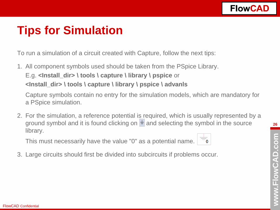
Tips for Simulation
To run a simulation of a circuit created with Capture, follow the next tips:
1. All component symbols used should be taken from the PSpice Library.
E.g. <Install_dir> \ tools \ capture \ library \ pspice or
<Install_dir> \ tools \ capture \ library \ pspice \ advanls
Capture symbols contain no entry for the simulation models, which are mandatory for
a PSpice simulation.
2. For the simulation, a reference potential is required, which is usually represented by a
ground symbol and it is found clicking on and selecting the symbol in the source
library.
This must necessarily have the value "0" as a potential name.
3. Large circuits should first be divided into subcircuits if problems occur.
ww
w.F
low
CA
D.c
om
27
FlowCAD Confidential
Types of Simulation

ww
w.F
low
CA
D.c
om
28
FlowCAD Confidential
Types of Simulation in PSpice
With PSpice, 4 basic types of simulation are possible. The type of simulation and the parameters for the project in
question are set and assigned via the simulation profiles. For all 4 types of simulation you will find examples on the
following 4 pages. The Solution / Samples folder contains a completely predefined example.
Bias Point
DC Current analysis
DC Sweep
DC analysis of all node
potentials
Time Domain (Transient)
Analysis of the time behavior
of electrical processes
AC Sweep
Frequency analysis of voltage
and current
(amplitude and phase)
ww
w.F
low
CA
D.c
om
29
FlowCAD Confidential
Bias Point (DC Analysis)
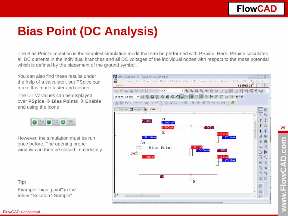
The Bias Point simulation is the simplest simulation mode that can be performed with PSpice. Here, PSpice calculates
all DC currents in the individual branches and all DC voltages of the individual nodes with respect to the mass potential
which is defined by the placement of the ground symbol.
You can also find these results under
the help of a calculator, but PSpice can
make this much faster and clearer.
The U-I-W values can be displayed
over PSpice Bias Points Enable
and using the icons
However, the simulation must be run
once before. The opening probe
window can then be closed immediately.
Tip:
Example "bias_point" in the
folder "Solution \ Sample"
ww
w.F
low
CA
D.c
om
30
FlowCAD Confidential
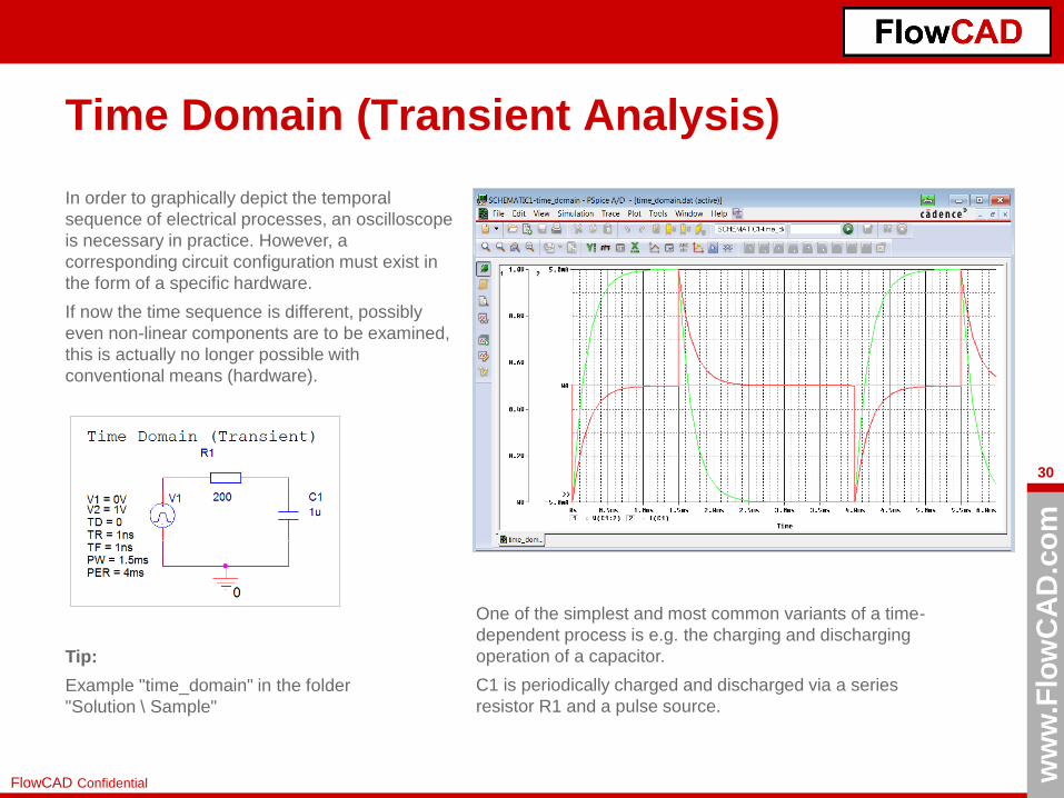
Time Domain (Transient Analysis)
In order to graphically depict the temporal
sequence of electrical processes, an oscilloscope
is necessary in practice. However, a
corresponding circuit configuration must exist in
the form of a specific hardware.
If now the time sequence is different, possibly
even non-linear components are to be examined,
this is actually no longer possible with
conventional means (hardware).
One of the simplest and most common variants of a time-
dependent process is e.g. the charging and discharging
operation of a capacitor.
C1 is periodically charged and discharged via a series
resistor R1 and a pulse source.
Tip:
Example "time_domain" in the folder
"Solution \ Sample"
ww
w.F
low
CA
D.c
om
31
FlowCAD Confidential
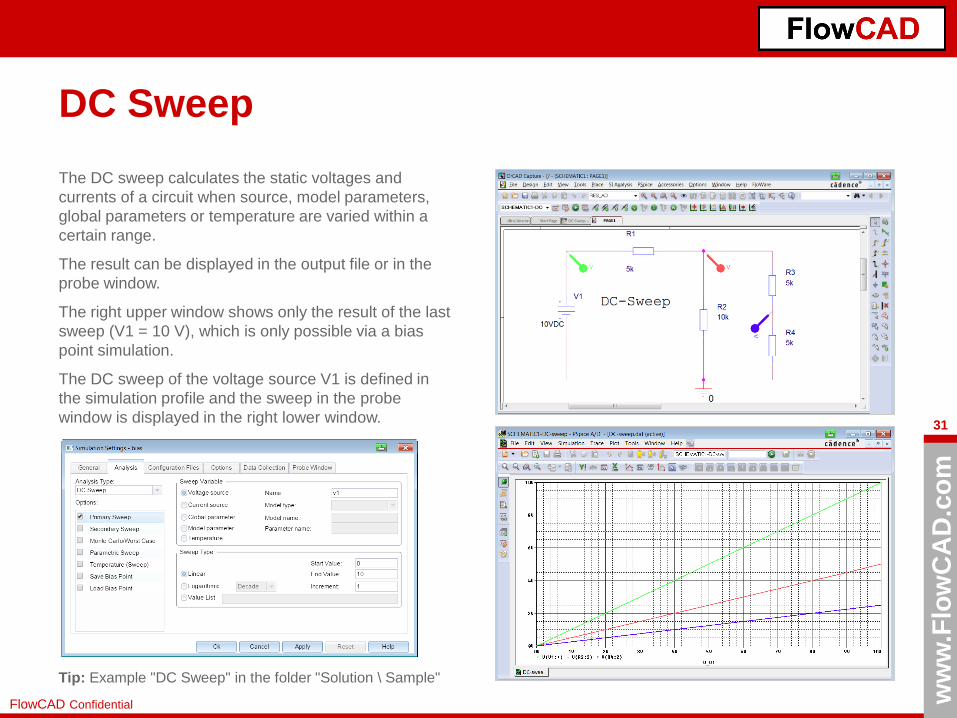
DC Sweep
The DC sweep calculates the static voltages and
currents of a circuit when source, model parameters,
global parameters or temperature are varied within a
certain range.
The result can be displayed in the output file or in the
probe window.
The right upper window shows only the result of the last
sweep (V1 = 10 V), which is only possible via a bias
point simulation.
The DC sweep of the voltage source V1 is defined in
the simulation profile and the sweep in the probe
window is displayed in the right lower window.
Tip: Example "DC Sweep" in the folder "Solution \ Sample"

ww
w.F
low
CA
D.c
om
32
FlowCAD Confidential
AC Sweep
The AC analysis calculates the small signal behavior of a
linear or linearized AC circuit as a function of the frequency.
These circuits may consist of linear components (RLC) or /
and non-linear components (transistors, diodes, etc.).
The AC sweep calculates the behavior of the circuit over a
predetermined frequency range by performing a series of
individual AC analyzes at different frequencies.
Tip:
Example "AC Sweep" in the
"Solution \ Sample" folder

ww
w.F
low
CA
D.c
om
33
FlowCAD Confidential
Simulation Options
With each simulation it is possible to include different options to run particular conditions:
• Temperature Sweep: Analyze how responds your design depending upon
temperature.
• Monte Carlo: Simulate taking into account tolerances or discrete components,
semiconductors, etc.
• Sensitivity Analysis: Find out, which components are sensitive or not very sensitive,
reduce the price and increase the quality of your design.
• Worst Case Analysis: Analyze the functional limits of your project.
• Parametric Sweep: Vary different parameters and visualize their effects.
• Noise Analysis

ww
w.F
low
CA
D.c
om
34
FlowCAD Confidential
Design Example:
Switched Mode Power Supply (SMPS)
ww
w.F
low
CA
D.c
om
35
FlowCAD Confidential
Goals
• You will firstly design the SMPS circuit shown previously, where a 50 Hz and 230 V
input signal will be converted into 5 V output. In this case a permanent 333 KHz
voltage pulse with Duty Cycle 20 % will be used to control the MOSFET, because due
to the Lite Version limitations, we cannot use the PWM IC.
• You will define different simulation profiles and analyze the results in the probe
window using markers and adding measurements.
Tip 1: You will find the overall circuit in the "Solution" folder.
Tip 2: For a better understanding of the software, it is recommended to design the circuit
yourself following the explained steps.
ww
w.F
low
CA
D.c
om
36
FlowCAD Confidential
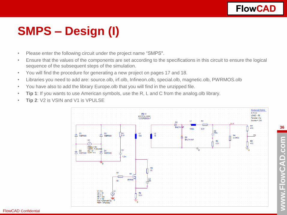
SMPS – Design (I)
• Please enter the following circuit under the project name “SMPS".
• Ensure that the values of the components are set according to the specifications in this circuit to ensure the logical
sequence of the subsequent steps of the simulation.
• You will find the procedure for generating a new project on pages 17 and 18.
• Libraries you need to add are: source.olb, irf.olb, Infineon.olb, special.olb, magnetic.olb, PWRMOS.olb
• You have also to add the library Europe.olb that you will find in the unzipped file.
• Tip 1: If you wants to use American symbols, use the R, L and C from the analog.olb library.
• Tip 2: V2 is VSIN and V1 is VPULSE

ww
w.F
low
CA
D.c
om
37
FlowCAD Confidential
SMPS – Design (II)
• How can you define the global parameters D,
LOAD, Periode and Source (upper right)?
1. Place the component param from the
library special.olb and make double click
on it
2. Click on New Property and complete
window with the global parameters. Start
with D and continue with the next ones.
3. Close the opened tab (automatically you
are seeing the circuit again) and save.
Tip: Global parameters are defined in the
components value between curly brackets { }.
ww
w.F
low
CA
D.c
om
38
FlowCAD Confidential
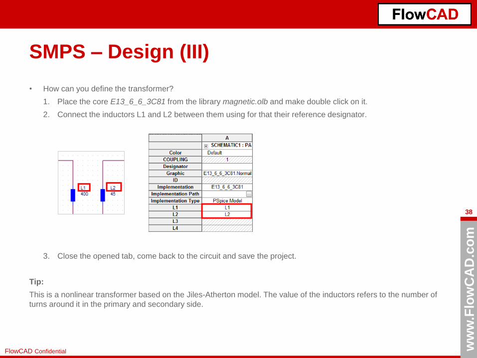
SMPS – Design (III)
• How can you define the transformer?
1. Place the core E13_6_6_3C81 from the library magnetic.olb and make double click on it.
2. Connect the inductors L1 and L2 between them using for that their reference designator.
3. Close the opened tab, come back to the circuit and save the project.
Tip:
This is a nonlinear transformer based on the Jiles-Atherton model. The value of the inductors refers to the number of
turns around it in the primary and secondary side.
ww
w.F
low
CA
D.c
om
39
FlowCAD Confidential
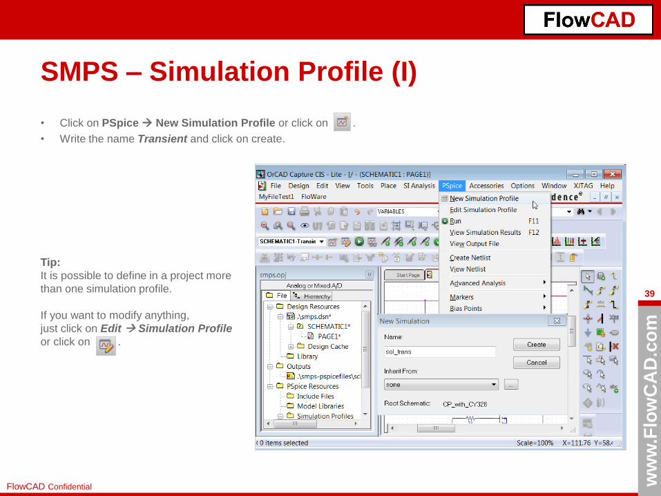
SMPS – Simulation Profile (I)
• Click on PSpice New Simulation Profile or click on .
• Write the name Transient and click on create.
Tip:
It is possible to define in a project more
than one simulation profile.
If you want to modify anything,
just click on Edit Simulation Profile
or click on .

ww
w.F
low
CA
D.c
om
40
FlowCAD Confidential
SMPS – Simulation Profile (II)
• Simulation Settings Window
pops up
• Under Analysis type, you define
the simulation type, the duration
of the simulation, and the step
size.
• Under Probe Window, you can
define what is displayed in the
probe window.
Tip:
If no value is entered under
Maximum Step Size, a default value
(Final Time / 50) is used as start
value, and the displayed curve may
be inaccurate.
However, a too little step increases
the simulation time significantly.
ww
w.F
low
CA
D.c
om
41
FlowCAD Confidential
SMPS – Simulation
• After the definition of the Simulation Profile, you can simulate the circuit.
• Click PSpice Run or F11 or .
• If you have designed the circuit as in the page 36, you will get opened the Probe Window, but no trace will be
shown, although you selected in the Simulation Settings „All markers on open schematic“, as you did not place
any marker.
• What can you do?
– You can place markers afterwards in the circuit, where you want to show the results without
additional simulation.
– You can click in the Probe Window on Trace Add Trace and select the trace you want to view.
Tip 1: V marker on the net connection, I marker on the component pin, W marker on the component
Tip 2: The simulation will take approximately 4 minutes, so you have time for a coffee.

ww
w.F
low
CA
D.c
om
42
FlowCAD Confidential
SMPS – Results (I): Rectified Voltage
• Place a Voltage Marker on the left side of V2, other on the right side and the last one
after the rectifier.
• What are we seeing?
– Red: Rectified AC-DC voltage
– Green: Positive input AC source
– Violet: Negative input AC source
Tip:
The color assignment takes place
according to a predefined sequence in
the pspice.ini file, and the
corresponding input sequence.
Evaluation:
The capacitor C1 (known as
reservoir capacitor) (1.2 mF) has
sufficient effect, that is why the
rectified wave is so flat.
On the next page, the U-I behavior
on the C1 is examined.
ww
w.F
low
CA
D.c
om
43
FlowCAD Confidential
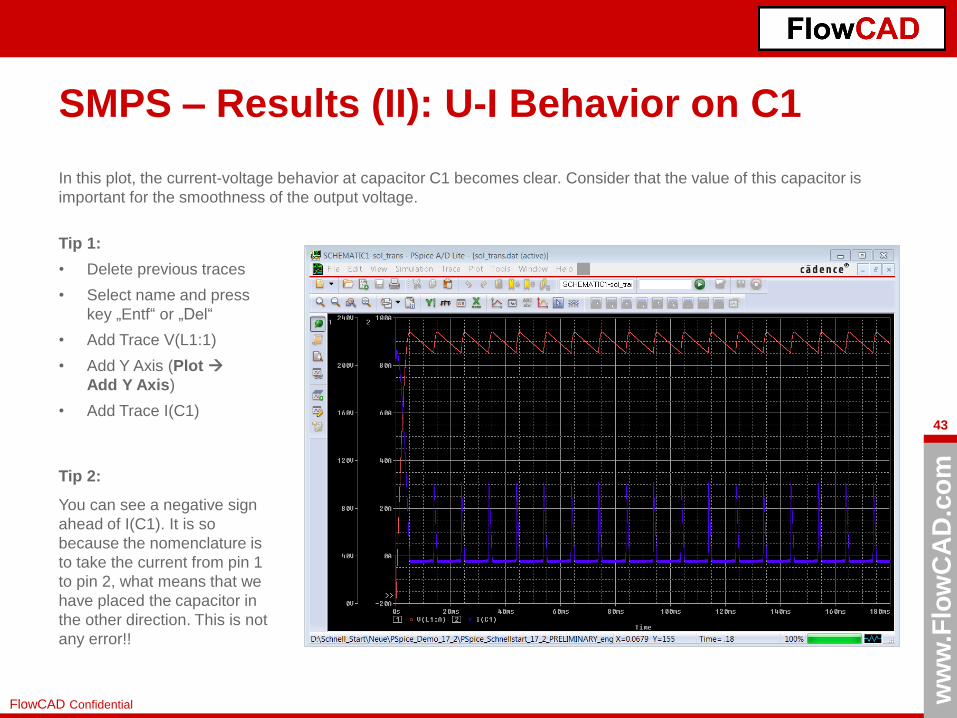
SMPS – Results (II): U-I Behavior on C1
In this plot, the current-voltage behavior at capacitor C1 becomes clear. Consider that the value of this capacitor is
important for the smoothness of the output voltage.
Tip 1:
• Delete previous traces
• Select name and press
key „Entf“ or „Del“
• Add Trace V(L1:1)
• Add Y Axis (Plot
Add Y Axis)
• Add Trace I(C1)
Tip 2:
You can see a negative sign
ahead of I(C1). It is so
because the nomenclature is
to take the current from pin 1
to pin 2, what means that we
have placed the capacitor in
the other direction. This is not
any error!!

ww
w.F
low
CA
D.c
om
44
FlowCAD Confidential
SMPS – Results (III): Generation of HF Signals
As we have designed a SMPS circuit using a voltage pulse of approximately 330 KHz, we have generated a high
frequency square wave, converting then DC to AC again. Signals in the secondary side of the circuit are now
isolated and converted to DC using the diodes D5 and D6 together with a LP Filter to eliminate the AC source. In
this procedure, the diode D5 is ON when MOSFET is ON and D6 is ON, when the MOSFET is OFF. L3 is driving
here (yellow) then the sum of both of them.
ww
w.F
low
CA
D.c
om
45
FlowCAD Confidential
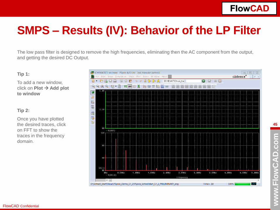
SMPS – Results (IV): Behavior of the LP Filter
The low pass filter is designed to remove the high frequencies, eliminating then the AC component from the output,
and getting the desired DC Output.
Tip 1:
To add a new window,
click on Plot Add plot
to window
Tip 2:
Once you have plotted
the desired traces, click
on FFT to show the
traces in the frequency
domain.

ww
w.F
low
CA
D.c
om
46
FlowCAD Confidential
SMPS – Results (V): Output Voltage
The DC voltage rises oscillating until it is stabilized to a value of approx. 5 V ("transient response") and is quite flat.
This smoothness is achieved thanks to the capacitor C1 (among other reasons) and the low pass filter we have used.

ww
w.F
low
CA
D.c
om
47
FlowCAD Confidential
SMPS – Parametric Sweep (I)
The Parametric Sweep allows you to simulate a circuit with different values of a component and to display the results in
a view with a single call.
How do you have to do it? Basically there are 4 steps.
1. Definition of a global variable
Place the part "Param" from the library special.olb somewhere
on the Schematic, it serves only as a placeholder for several
global variables, here the nominal value for R4 (50 Ohm).
2. Specify the component using
this global variable
To do this, double-click on the
value of the desired component
and confirm with "OK". Be sure to
use the curly brackets "{}“.

ww
w.F
low
CA
D.c
om
48
FlowCAD Confidential
SMPS – Parametric Sweep (II)
3. Assign and Display global variables in the Schematic
Double-click "Parameters" and perform the following steps:
• New Property in the Property Editor
• "LOAD", "50" in Add New Row Window
• Apply in Add New Row Window
• Exit from Add New Property with Cancel
• LOAD is added as a new property
• Select “LOAD" and use display
• Display Properties on "Name and Value“
• Do the same for “D”, “Periode” and
“Source”
• After confirming with "OK", the entries are
visible under Parameters.
Tip:
You can also enter several
variables under Parameters.
ww
w.F
low
CA
D.c
om
49
FlowCAD Confidential
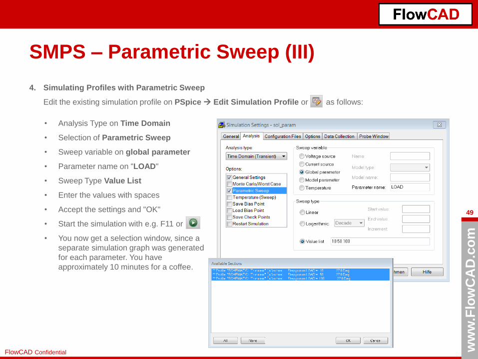
SMPS – Parametric Sweep (III)
4. Simulating Profiles with Parametric Sweep
Edit the existing simulation profile on PSpice Edit Simulation Profile or as follows:
• Analysis Type on Time Domain
• Selection of Parametric Sweep
• Sweep variable on global parameter
• Parameter name on “LOAD"
• Sweep Type Value List
• Enter the values with spaces
• Accept the settings and "OK"
• Start the simulation with e.g. F11 or
• You now get a selection window, since a
separate simulation graph was generated
for each parameter. You have
approximately 10 minutes for a coffee.
ww
w.F
low
CA
D.c
om
50
FlowCAD Confidential
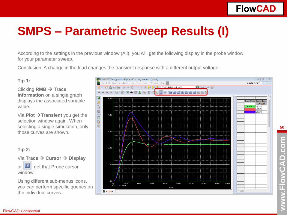
SMPS – Parametric Sweep Results (I)
According to the settings in the previous window (All), you will get the following display in the probe window
for your parameter sweep.
Conclusion: A change in the load changes the transient response with a different output voltage.
Tip 1:
Clicking RMB Trace
Information on a single graph
displays the associated variable
value.
Via Plot Transient you get the
selection window again. When
selecting a single simulation, only
those curves are shown.
Tip 2:
Via Trace Cursor Display
or get that Probe cursor
window.
Using different sub-menus icons,
you can perform specific queries on
the individual curves.
ww
w.F
low
CA
D.c
om
51
FlowCAD Confidential
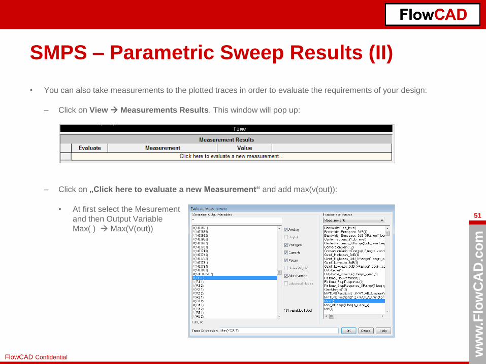
SMPS – Parametric Sweep Results (II)
• You can also take measurements to the plotted traces in order to evaluate the requirements of your design:
– Click on View Measurements Results. This window will pop up:
– Click on „Click here to evaluate a new Measurement“ and add max(v(out)):
• At first select the Mesurement
and then Output Variable
Max( ) Max(V(out))

ww
w.F
low
CA
D.c
om
52
FlowCAD Confidential
SMPS – Parametric Sweep Results (III)
– Visualize the maximum value for each particular trace
• You can also use the Toggle Cursors to take measurements between traces in the X and Y axis.
• There are 2 Cursors available with 2 kinds of cursor probe windows:
– Click on and one of these 2 windows will pop up.
New style Old style
– To change style use: „Tools Options Cursor Settings

ww
w.F
low
CA
D.c
om
53
FlowCAD Confidential
SMPS – Parametric Sweep Results (IV)
• Use cursor 1 with the LMB (Left Mouse Button) and cursor 2 with RMB to measure e.g. the time difference between
maximum values.
Max Values are:
5.3853 V and 7.5983 V
Time between is:
54.817 ms

ww
w.F
low
CA
D.c
om
54
FlowCAD Confidential
Final Remarks
• After performing all the examples included in this Quick Launch, you should be able to
perform simple simulations with PSpice and its basic functions.
• This does not replace, of course, any PSpice training as it is given by FlowCAD or
Cadence. It is only intended to provide the most important steps necessary to get an
overview of the possibilities of PSpice.
• If the PSpice models can not be found in the standard library, you can always ask
directly to the manufacturer. These models can also be included in the demo version,
opening the Simulation Settings of your simulation profile and adding them from the
Configuration Files tab. In addition, PSpice also has a powerful model editor, you can
use to create your own models from datasheets.
• Do you want PSpice to simulate mechanical elements, e.g. of shock absorber of a
vehicle or of an electric windscreen lifter, which is quite possible, you must use
electrical replacement models for those mechanical elements, which of course are not
a part of the usual libraries shipped by Cadence.
• In case you have digital and analog signals coexisting in the same circuit, take into
account that PSpice supports analog and digital simulation at the same time in one
simulation.

ww
w.F
low
CA
D.c
om
55
FlowCAD Confidential
PSpice Extensions
• PSpice is not only thought as an analog / digital simulator, but as a tool to improve the
performance, reliability, productivity, predictability, costs and quality of your circuits,
using Sensitivity Analysis, Monte Carlo Analysis, Smoke Analysis and Optimizer from
PSpice Advanced Analysis Option.
• PSpice also allows simulation of mixed signal systems thanks to the possibility to
abstract the functionality of models like microcontrollers, microprocessors, etc. using
C / C++, SystemC and Verilog-A languages. It allows to evaluate the whole system
with its algorithms in only one simulator platform.
• Another possibility to extend PSpice's application area is to link PSpice to MATLAB.
For this, Cadence offers an adjustable interface SLPS (Simulink-PSpice), which
enables co-simulation with MATLAB and also the choice to send data to MATLAB for
post-processing and the use of MATLAB Block Functions in the PSpice environment.

ww
w.F
low
CA
D.c
om
56
FlowCAD Confidential
FlowCAD Deutschland
Mozartstr. 2
85622 Feldkirchen bei München
T +49 89 4563-7770
F +49 89 4563-7790
FlowCAD Schweiz
Hintermättlistr. 1
5506 Mägenwil
T +41 56 485 91 91
F +41 56 485 91 95
FlowCAD Polen
ulica Sasiedzka 2A
80-298 Gdansk
T +48 58 342 75 94
F +48 58 342 70 60
Für weitere Fragen und Informationen stehen wir gerne zur Verfügung
Please don‘t hesitate to contact us
Kontakt zu FlowCAD / Contact us

ww
w.F
low
CA
D.c
om
57
FlowCAD Confidential