Quick Start Guide Safety...
18
CREATED BY ® Quick Start Guide & Safety Information February 1, 2012
Transcript of Quick Start Guide Safety...
CREATED BY
®
Quick Start Guide
&
Safety Information
February 1, 2012

Table of Contents
2
Important Safety Instructions 3 Important Notice – Software and Firmware Updates 4 Important Notice – Cooling Fan Operation 4 VoIP Interface Statement 4 Support Contact Information 4 Audia Quick Start 5 Connecting to a networked system using Audia with CobraNet 5 Connecting to standalone unit using Audia without CobraNet (AudiaSOLO) 10 AudiaFLEX Optional Telephone Interface TI-2 14 Telecom Connection Instructions 14 Warranty 15
3
Important Safety Instructions
1) Read these instructions.
2) Keep these instructions.
3) Heed all warnings.
4) Follow all instructions.
5) Do not use this product near water.
6) Clean only with dry cloth.
7) Do not block ventilation openings. Install in accordance with the manufacturer’s instructions.
8) Do not install near any heat sources such as radiators, heat registers, stoves, or other product (including amplifiers) that produce heat.
9) Do not defeat the safety purpose of the grounding-type plug. A grounding type plug has two blades and a third grounding prong.
The third prong is provided for your safety. If the provided plug does not fit into your outlet, consult an electrician for replacement of the obsolete outlet.
10) Protect the power cord from being walked on or pinched particularly at plugs, convenience receptacles, and the point where they exit from the product.
11) Only use attachments/accessories specified by the manufacturer.
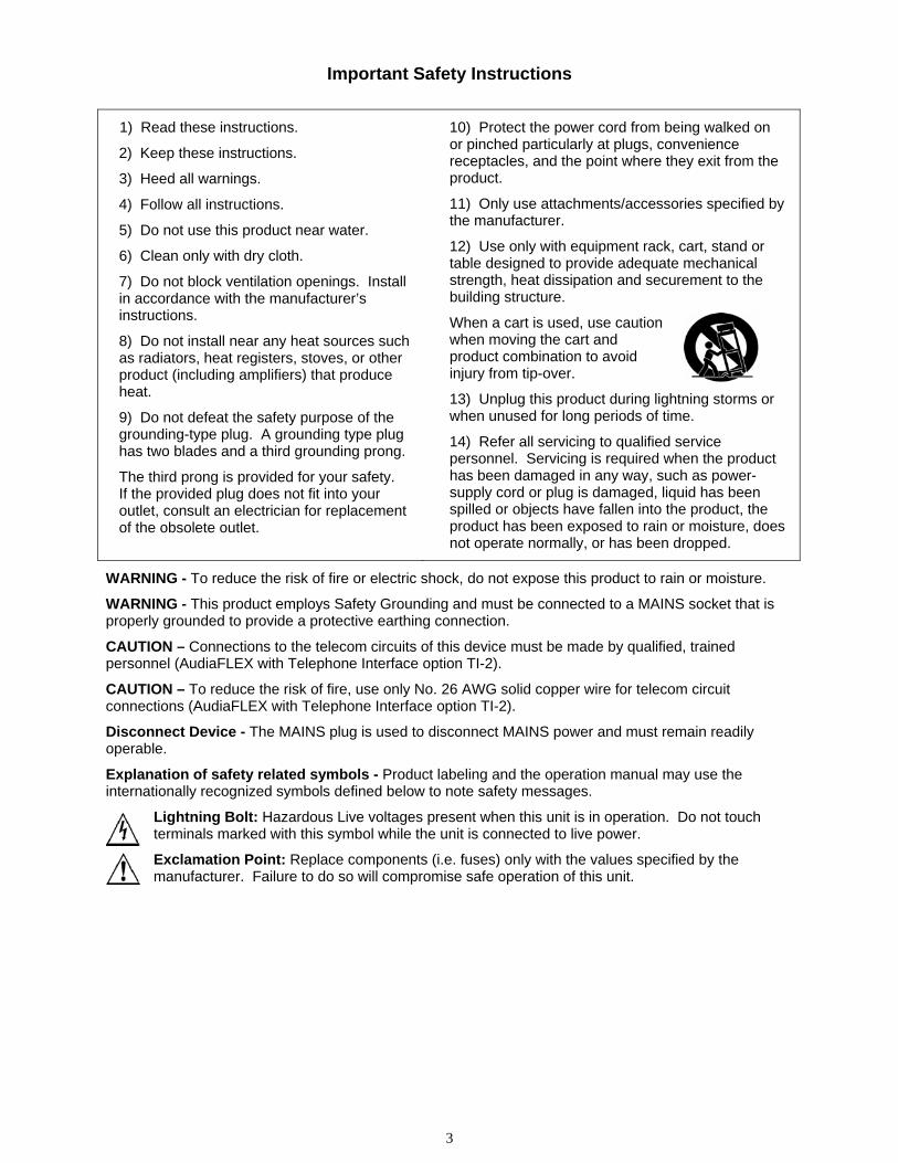
12) Use only with equipment rack, cart, stand or table designed to provide adequate mechanical strength, heat dissipation and securement to the building structure.
When a cart is used, use caution when moving the cart and product combination to avoid injury from tip-over.
13) Unplug this product during lightning storms or when unused for long periods of time.
14) Refer all servicing to qualified service personnel. Servicing is required when the product has been damaged in any way, such as power-supply cord or plug is damaged, liquid has been spilled or objects have fallen into the product, the product has been exposed to rain or moisture, does not operate normally, or has been dropped.
WARNING - To reduce the risk of fire or electric shock, do not expose this product to rain or moisture.
WARNING - This product employs Safety Grounding and must be connected to a MAINS socket that is properly grounded to provide a protective earthing connection.
CAUTION – Connections to the telecom circuits of this device must be made by qualified, trained personnel (AudiaFLEX with Telephone Interface option TI-2).
CAUTION – To reduce the risk of fire, use only No. 26 AWG solid copper wire for telecom circuit connections (AudiaFLEX with Telephone Interface option TI-2).
Disconnect Device - The MAINS plug is used to disconnect MAINS power and must remain readily operable.
Explanation of safety related symbols - Product labeling and the operation manual may use the internationally recognized symbols defined below to note safety messages.
Lightning Bolt: Hazardous Live voltages present when this unit is in operation. Do not touch terminals marked with this symbol while the unit is connected to live power.
Exclamation Point: Replace components (i.e. fuses) only with the values specified by the manufacturer. Failure to do so will compromise safe operation of this unit.

4
IMPORTANT NOTICE - SOFTWARE AND FIRMWARE UPDATES
To ensure that your AUDIA installation uses the latest software and firmware releases, please immediately visit BIAMP’s web page at www.biamp.com/audia.
If an update is required in this unit, both software and firmware can be easily downloaded from the web page.
The latest versions of software and firmware provide the most reliable operation and current features.
IMPORTANT NOTICE - COOLING FAN OPERATION
AUDIA products feature a temperature-controlled fan. When this unit is first powered on the fan will run briefly as a test. After the test is complete the fan will not run again until required by internal temperatures. In many environments the fan will not need to run at all.
VoIP Interface Statement
The VoIP-2 card requires the use of a SIP connection with any VoIP system. Enabling a SIP connection may require the purchase of a third party license and/or additional software from the VoIP system manufacturer. Manual software configuration of the VoIP-2 card is necessary for proper operation.
Please consult with your IT professional or VoIP system professional regarding proper configuration.
Support Contact Information
For technical or application support contact BIAMP’s field support team Applications Engineering Group
By EMAIL: [email protected]
By telephone: US and Canada (toll-free) 800.826.1457 Outside North America +503.641.7287 Brisbane Office +61.(0)7.3552.9552 Hong Kong Office +852.6473.8148 London Office +44.(0)7775.941.428 Mumbai Office +91.9967.605.101
By FAX: US and Canada 503.626.0281 Outside North America +1.503.626.0281
5
Audia Quick Start For more complete instructions, see the software Help file or the printable Help document (on CD).
Connecting to a networked system using Audia with CobraNet
1. Install Audia software on a Windows® XP/7 Professional PC PC must have a 10/100baseT NIC.
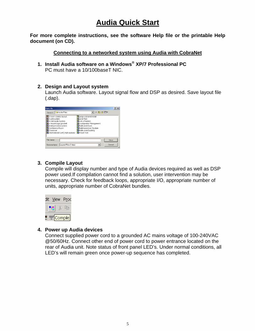
2. Design and Layout system Launch Audia software. Layout signal flow and DSP as desired. Save layout file (.dap).
3. Compile Layout Compile will display number and type of Audia devices required as well as DSP power used.If compilation cannot find a solution, user intervention may be necessary. Check for feedback loops, appropriate I/O, appropriate number of units, appropriate number of CobraNet bundles.
4. Power up Audia devices Connect supplied power cord to a grounded AC mains voltage of 100-240VAC @50/60Hz. Connect other end of power cord to power entrance located on the rear of Audia unit. Note status of front panel LED’s. Under normal conditions, all LED’s will remain green once power-up sequence has completed.
6
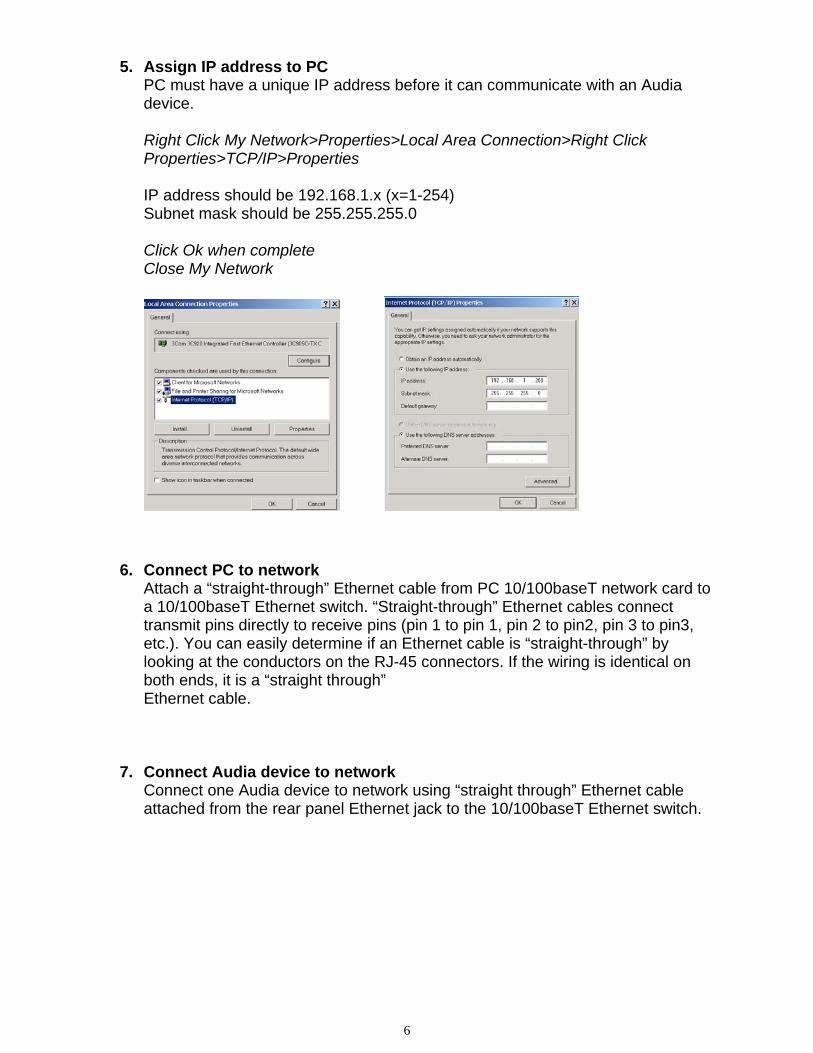
5. Assign IP address to PC PC must have a unique IP address before it can communicate with an Audia device. Right Click My Network>Properties>Local Area Connection>Right Click Properties>TCP/IP>Properties IP address should be 192.168.1.x (x=1-254) Subnet mask should be 255.255.255.0 Click Ok when complete Close My Network
6. Connect PC to network
Attach a “straight-through” Ethernet cable from PC 10/100baseT network card to a 10/100baseT Ethernet switch. “Straight-through” Ethernet cables connect transmit pins directly to receive pins (pin 1 to pin 1, pin 2 to pin2, pin 3 to pin3, etc.). You can easily determine if an Ethernet cable is “straight-through” by looking at the conductors on the RJ-45 connectors. If the wiring is identical on both ends, it is a “straight through” Ethernet cable.
7. Connect Audia device to network Connect one Audia device to network using “straight through” Ethernet cable attached from the rear panel Ethernet jack to the 10/100baseT Ethernet switch.
7
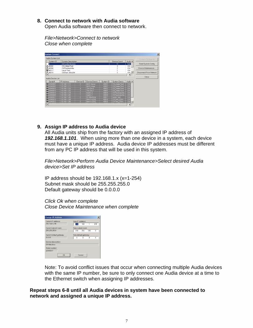
8. Connect to network with Audia software Open Audia software then connect to network. File>Network>Connect to network Close when complete
9. Assign IP address to Audia device All Audia units ship from the factory with an assigned IP address of 192.168.1.101. When using more than one device in a system, each device must have a unique IP address. Audia device IP addresses must be different from any PC IP address that will be used in this system. File>Network>Perform Audia Device Maintenance>Select desired Audia device>Set IP address IP address should be 192.168.1.x (x=1-254) Subnet mask should be 255.255.255.0 Default gateway should be 0.0.0.0 Click Ok when complete Close Device Maintenance when complete
Note: To avoid conflict issues that occur when connecting multiple Audia devices with the same IP number, be sure to only connect one Audia device at a time to the Ethernet switch when assigning IP addresses.
Repeat steps 6-8 until all Audia devices in system have been connected to network and assigned a unique IP address.

8
10. Connect CobraNet For multi-unit systems, “straight-through” Ethernet cables must be connected from the rear panel CobraNet jack of each unit to a 100baseT Ethernet switch.
11. Open layout (.dap) file File>Open>Select file
12. Enter appropriate Audia unit serial numbers to equipment table Tools>Equipment table>Select desired Audia unit(s) Select OK when complete
13. Send Configuration File>Network>Send System Configuration Sends layout configuration to selected Audia unit(s).

9
14. Start Audio
15. Adjust component parameters as needed
Optional: 16. Disconnect PC from Audia system
File>Network>Disconnect from Audia system
17. Disconnect PC from Network File>Network>Disconnect from network
10
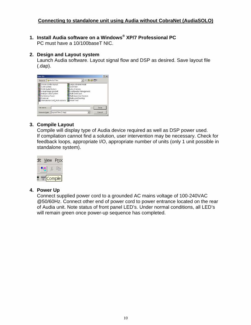
Connecting to standalone unit using Audia without CobraNet (AudiaSOLO) 1. Install Audia software on a Windows® XP/7 Professional PC
PC must have a 10/100baseT NIC. 2. Design and Layout system
Launch Audia software. Layout signal flow and DSP as desired. Save layout file (.dap).
3. Compile Layout Compile will display type of Audia device required as well as DSP power used. If compilation cannot find a solution, user intervention may be necessary. Check for feedback loops, appropriate I/O, appropriate number of units (only 1 unit possible in standalone system).
4. Power Up Connect supplied power cord to a grounded AC mains voltage of 100-240VAC @50/60Hz. Connect other end of power cord to power entrance located on the rear of Audia unit. Note status of front panel LED’s. Under normal conditions, all LED’s will remain green once power-up sequence has completed.

11
5. Assign IP address to PC PC must have a unique IP address before it can communicate with an Audia device. Right Click My Network>Properties>Local Area Connection>Right Click Properties>TCP/IP>Properties IP address should be 192.168.1.x (x=1-254) Subnet mask should be 255.255.255.0 Click Ok when complete Close My Network
6. Connect PC to Audia unit
Connect “cross-over” Ethernet cable (supplied with unit) from PC 10/100baseT Ethernet card to Ethernet jack located on rear panel of Audia unit. “Cross-over” Ethernet cables have their pins swapped (pin 1 to pin 3, pin 2 to pin 6, pin3 to pin1) and can easily be identified by looking at the conductors on the RJ-45 connectors. If the wiring is different at each end, it is a “cross-over” cable.
7. Connect to Audia unit with Audia software Open Audia software then connect to unit. File>Network>Connect to network Close when complete

12
8. Open layout (.dap) file File>Open>Select file
9. Enter appropriate Audia unit serial to equipment table Tools>Equipment table>Select desired Audia unit Select OK when complete
10. Send Configuration File>Network>Send System Configuration Sends layout configuration to selected Audia unit.

13
11. Start Audio
12. Adjust component parameters as needed
Optional:
13. Disconnect PC from Audia system File>Network>Disconnect from Audia system
14. Disconnect PC from Network File>Network>Disconnect from network
14
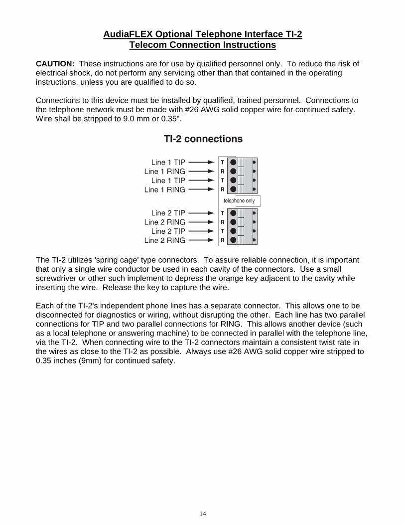
AudiaFLEX Optional Telephone Interface TI-2 Telecom Connection Instructions
CAUTION: These instructions are for use by qualified personnel only. To reduce the risk of electrical shock, do not perform any servicing other than that contained in the operating instructions, unless you are qualified to do so. Connections to this device must be installed by qualified, trained personnel. Connections to the telephone network must be made with #26 AWG solid copper wire for continued safety. Wire shall be stripped to 9.0 mm or 0.35".
T
R
T
R
T
telephone only
R
T
R
Line 1 TIPLine 1 RING
Line 1 TIPLine 1 RING
TI-2 connections
Line 2 TIPLine 2 RING
Line 2 TIPLine 2 RING
The TI-2 utilizes 'spring cage' type connectors. To assure reliable connection, it is important that only a single wire conductor be used in each cavity of the connectors. Use a small screwdriver or other such implement to depress the orange key adjacent to the cavity while inserting the wire. Release the key to capture the wire. Each of the TI-2's independent phone lines has a separate connector. This allows one to be disconnected for diagnostics or wiring, without disrupting the other. Each line has two parallel connections for TIP and two parallel connections for RING. This allows another device (such as a local telephone or answering machine) to be connected in parallel with the telephone line, via the TI-2. When connecting wire to the TI-2 connectors maintain a consistent twist rate in the wires as close to the TI-2 as possible. Always use #26 AWG solid copper wire stripped to 0.35 inches (9mm) for continued safety.
15
WARRANTY
BIAMP SYSTEMS IS PLEASED TO EXTEND THE FOLLOWING 5-YEAR LIMITED WARRANTY TO THE ORIGINAL PURCHASER OF THE PROFESSIONAL SOUND EQUIPMENT DESCRIBED IN THIS MANUAL
1. BIAMP Systems warrants to the original purchaser of new products that the product will be free from defects in material and workmanship for a period of 5 YEARS from the date of purchase from an authorized BIAMP Systems dealer, subject to the terms and conditions set forth below. 2. If you notify BIAMP during the warranty period that a BIAMP Systems product fails to comply with the warranty, BIAMP Systems will repair or replace, at BIAMP Systems' option, the nonconforming product. As a condition to receiving the benefits of this warranty, you must provide BIAMP Systems with documentation that establishes that you were the original purchaser of the products. Such evidence may consist of your sales receipt from an authorized BIAMP Systems dealer. Transportation and insurance charges to and from the BIAMP Systems factory for warranty service shall be your responsibility. 3. This warranty will be VOID if the serial number has been removed or defaced; or if the product has been altered, subjected to damage, abuse or rental usage, repaired by any person not authorized by BIAMP Systems to make repairs; or installed in any manner that does not comply with BIAMP Systems' recommendations. 4. Electro-mechanical fans, electrolytic capacitors, gooseneck microphones, cords connecting handheld microphones, hard-drives, displays, and normal wear and tear of items such as paint, knobs, handles, keypads and covers are not covered under this warranty. All server-based devices are warranted for 3 years only. 5. This warranty is in lieu of all other warranties, expressed or implied. BIAMP Systems disclaims all other warranties, expressed or implied, including, but not limited to, implied warranties of merchantability and fitness for a particular purpose. 6. The remedies set forth herein shall be the purchaser's sole and exclusive remedies with respect to any defective product. 7. No agent, employee, distributor or dealer of BIAMP Systems is authorized to modify this warranty or to make additional warranties on behalf of BIAMP Systems. Statements, representations or warranties made by any dealer do not constitute warranties by BIAMP Systems. BIAMP Systems shall not be responsible or liable for any statement, representation or warranty made by any dealer or other person. 8. No action for breach of this warranty may be commenced more than one year after the expiration of this warranty. 9. BIAMP Systems shall not be liable for special, indirect, incidental, or consequential damages, including lost profits or loss of use arising out of the purchase, sale, or use of the products, even if BIAMP Systems was advised of the possibility of such damages.
Biamp Systems 9300 SW Gemini Drive
Beaverton, Oregon 97008 (503) 641-7287

COMPLIANCE
16
FCC Notice - Class B digital device:
This equipment has been tested and found to comply with the limits for a Class B digital device, pursuant to Part 15 of the FCC Rules. These limits are designed to provide reasonable protection against harmful interference in a residential as well as in a commercial environment. This equipment generates, uses, and can radiate radio frequency energy and, if not installed and used in accordance with the instructions, may cause harmful interference to radio communications. However, there is no guarantee that interference will not occur in a particular installation. If this equipment does cause harmful interference to radio or television reception, which can be determined by turning the equipment off and on, the user is encouraged to try to correct the interference by one or more of the following measures: 1) Reorient or relocate the receiving antenna, 2) Increase the separation between the equipment and receiver, 3) Connect the equipment into an outlet on a circuit different from that to which the receiver is connected, or 4) Consult the dealer or an experienced radio/TV technician for help.
Telephone Interface Information:
This equipment complies with Part 68 of the FCC rules and the requirements adopted by the ACTA. On the rear panel of this equipment are markings that contain, among other information, telecom product identifier US:6RMBR00BAUDIATI-2. If requested, this number must be provided to the telephone company.
This equipment is designed for modular connection with Universal Service Order Codes (USOC) RJ-11C, RJ-11W, RJ-14C, RJ-14W.
A plug and jack used to connect this equipment to the premises wiring and telephone network must comply with the applicable FCC Part 68 rules and requirements adopted by the ACTA. A compliant telephone cord and modular plug is provided with this product. It is designed to be connected to a compatible modular jack that is also compliant. See installation instructions for details.
Ringer Equivalency Number (REN) - The REN is used to determine the number of devices that may be connected to a telephone line. Excessive RENs on a telephone line may result in the devices not ringing in response to an incoming call. In most but not all areas, the sum of RENs should not exceed five (5.0). To be certain of the number of devices that may be connected to a line, as determined by the total RENs, contact the local telephone company. The REN for this product is 0.0 as indicated by part of the product identifier that has the format US:AAAEQ##TXXXX. The digits represented by ## are the REN without a decimal point (e.g., 00 is a REN of 0.0).
Alarms connected to telephone line - If your facility has specially wired alarm equipment connected to the telephone line, ensure the installation of this US:6RMBR00BAUDIATI-2 does not disable your alarm equipment. If you have questions about what will disable alarm equipment, consult your telephone company or a qualified installer.
Automatic Dialer: WHEN PROGRAMMING EMERGENCY NUMBERS AND(OR) MAKING TEST CALLS TO EMERGENCY NUMBERS:
1) Remain on the line and briefly explain to the dispatcher the reason for the call.
2) Perform such activities in the off-peak hours, such as early morning or late evenings.
Electrical Safety Advisory: Telephone companies report that electrical surges, typically lightning transients, are very destructive to customer terminal equipment connected to AC power sources. The use of a surge arrestor on the telephone line is recommended, particularly in areas that are prone to lightning strikes.
Service - This equipment is not user serviceable. If trouble is experienced with this equipment US:6RMBR00BAUDIATI-2, for repair or warranty information, please contact Biamp Systems Corporation, phone number 503.641.7287. If the equipment is causing harm to the telephone network, the telephone company may request that you disconnect the equipment until the problem is resolved.
If this equipment US:6RMBR00BAUDIATI-2 causes harm to the telephone network, the telephone company will notify you in advance that temporary discontinuance of service may be required. But if advance notice isn't practical, the telephone company will notify the customer as soon as possible. Also, you will be advised of your right to file a complaint with the FCC if you believe it is necessary.
The telephone company may make changes in its facilities, equipment, operations or procedures that could affect the operation of the equipment. If this happens, the telephone company will provide advance notice in order for you to make necessary modifications to maintain uninterrupted service.
Party Lines - Connection to party line service is subject to state tariffs. Contact the state public utility commission, public service commission or corporation commission for information.
COMPLIANCE
17
EC Declaration of Conformity
Biamp Systems Corporation, as manufacturer having sole responsibility, hereby declares that the following described product complies with the applicable provisions of the DIRECTIVES below except as noted herein. Any alterations to the product not agreed upon and directed by Biamp Systems Corporation will invalidate this declaration.
Product: Models:
Audio DSP Platforms: AudiaFLEX, AudiaFUSION, AudiaSOLO
AudiaFLEX I/O Cards AEC-2HD, IP-2, OP-2e, PA-2, TI-2, VoIP-2
AudiaFUSION Amplifier Cards AM-600, AM-600c
Low Voltage Controls: Select 8, Volume 8, Volume / Select 8, Logic Box, Voltage Control Box, Remote Control Bus Hub, RP-L1, RP-L2, RP-S4
Product Description: Audio Digital Signal Processors and Control Accessories
Applicable EC Directives: Applicable Harmonized Standards:
LVD Directive (2006/95/EC) Safety EN 60065:2001
EMC Directive (2004/108/EC) Emissions EN 55103-1:1996, Environment E2 Immunity EN 55103-2:1996, Environment E2
R&TTE Directive (1999/5/EC) TBR-21 (AudiaFLEX with TI-2 only)
Special Considerations for Product Environment or Compliance:
Shielded cabling must be used for system connections.
Technical Documentation File, Location and Contact:
Biamp Systems Corporation phone: (503) 641.7287 9300 S.W. Gemini Drive fax: (503) 626.0281 Beaverton, OR USA 97008 e-mail: [email protected]
Authorized Representative: Larry Copley, Compliance Engineer
Authorized Signature:
Issued: March 2010 Revised: March 2011

Biamp Systems | 9300 S.W. Gemini Drive | Beaverton, OR | 97008 | USA | +1.503.641.7287 | www.biamp.com
RoHS COMPLIANT
This Biamp product, including all attendant cables and accessories supplied by Biamp, meets all requirements of EU Directives 2002/95/EC of January 27, 2003, and 2005/618/EC of August 18, 2005, the EU RoHS Directives. An EU RoHS Materials Content Declaration document may be obtained at www.biamp.com
(This information is presented to comply with the requirements of Chinese law SJ/T11363-2006)
有害物质表 (Hazardous Substances Table) Biamp Systems Corporation
数字信号处理器 (Digital Signal Processor) 型号 AudiaFLEX, AudiaSOLO 数字信号处理器与放大器 (Digital Signal Processor and Amplifier) 型号 AudiaFUSION
部件名称 (Part Name)
有毒有害物质或元素 (Substances) Pb 铅
Hg 汞
Cd 镉
Cr+6 六价铬
PBB PBDE
设备机箱 (Equipment Chassis) X O X O O O
电源线 (Power Cord) O O O O O O
插拔式接线端子 (Plug-in Terminal Blocks) O O O O O O
光盘(CD ROM) O O O O O O
手册和其他书面文档 (Manual and Paper Documents) O O O O O O
包装箱和所有包装材料 (Box and Packing Materials) O O O O O O
以太网交叉电缆 Ethernet Crossover Cable O O O O O O
0:表示该部件所有均质材料中的这种有毒有害物质低于 SJ/T11363-2006 的限制要求.
X:表示该部件中至少有一种均质材料所含的这种有毒有害物质高于 SJ/T11363-2006 的限制要求.
在电触头和(或)镀镉所含的均质材料中,镉及其化合物的含量可以超过 0.01%,但欧盟指令 91/338/EEC(根据欧盟指令
76/769/EEC)限制销售和使用某些危险物质和制剂部分中所禁止的用途除外
在以下一种或多种物质所含的均质材料中,铅及其化合物的含量可以超过 0.1%:
1) 电子元器件中玻璃内所含的铅
2) 铅在钢材中是作为一种合金元素,含量可达 0.35%
3) 铅在铝材中是作为一种合金元素,含量可达 0.4%
4) 铅在铜材中是作为一种合金元素,含量可达 4%
5) 高熔点类焊料中的铅(即铅料合金,铅含量超过 85%)
6) 电子陶瓷部件内的铅
7) 由两种以上元素组成的焊料中所含的铅,用于连接针脚和微处理器包装,其中
铅的含量超过 80% 但低于 85%
8) 顺应针连接系统内的铅
9) 倒装芯片封装中半导体芯片及载体之间形成可靠连接所用焊料中的
在正常使用情况下,中国环保使用期限为 10 年,条件是: • 环境温度为 (Ambient Temperature) 0-40C (32-104°F) • 湿度为 0-95%,无凝结 • 海拔高度为 0-10,000 英尺 • 气流不受阻碍 • 没有水或其他液体进入任何部件 • 电源为 (Power Supply) 110-or 220 Vac, 50/60 Hz • 部件没有损坏(损坏部件应立即修理) • 由工厂授权人员使用批准的材料进行所有维修