
Quick Reference USTR 2453b - Biotech · Quick Reference T-Series TFF Cassettes with ... TFF Process...
38
Quick Reference T-Series TFF Cassettes with Omega™ and Delta Membranes For use with Centramate™ and Centrasette™ TFF Systems USTR 2453b
Transcript of Quick Reference USTR 2453b - Biotech · Quick Reference T-Series TFF Cassettes with ... TFF Process...
Quick Reference
T-Series TFF Cassettes with Omega™ and Delta MembranesFor use with Centramate™ and Centrasette™ TFF Systems
USTR 2453b
2
Contents
Safety Notice ..........................................................................................................................3
Learn About Safety.................................................................................................................4
TFF Process Flowchart ..........................................................................................................5
Introduction and Key to Diagrams ........................................................................................6
Step 1. Installation..................................................................................................................7
Step 2. Measuring Critical Volumes ......................................................................................9
Step 3. Flushing....................................................................................................................11
Step 4. Sanitization ..............................................................................................................13
Step 5. Normalized Water Permeability (NWP)...................................................................15
Step 6. Integrity Testing .......................................................................................................17
Step 7. Buffer Conditioning .................................................................................................19
Step 8. Optimization.............................................................................................................21
Step 9. Concentration ..........................................................................................................23
Step 10. Diafiltration.............................................................................................................25
Step 11. Product Recovery..................................................................................................27
Step 12. Buffer Flush............................................................................................................29
Step 13. Clean in Place (CIP)...............................................................................................31
Step 14. Storage...................................................................................................................33
Torque Recommendations...................................................................................................35
Operating Specifications......................................................................................................35
Temperature Correction Factors..........................................................................................36
Diafiltration — Continuous vs. Discontinuous ....................................................................37
Conversion Tables ................................................................................................................37
www.pall.com/biopharm 3
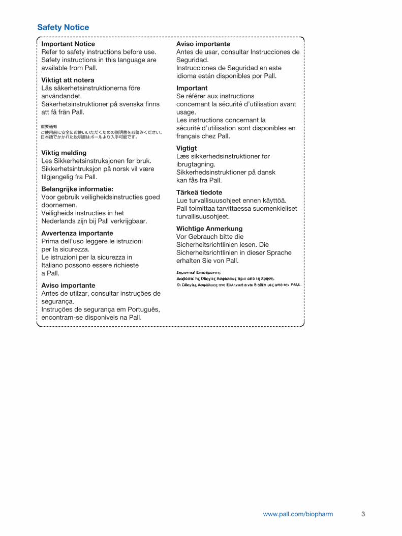
Safety Notice
Important NoticeRefer to safety instructions before use.Safety instructions in this language areavailable from Pall.
Viktigt att noteraLäs säkerhetsinstruktionerna föreanvändandet.Säkerhetsinstruktioner på svenska finnsatt få frän Pall.
Viktig meldingLes Sikkerhetsinstruksjonen før bruk.Sikkerhetsintruksjon på norsk vil væretilgjengelig fra Pall.
Belangrijke informatie:Voor gebruik veiligheidsinstructies goeddoornemen.Veiligheids instructies in hetNederlands zijn bij Pall verkrijgbaar.
Avvertenza importantePrima dell’uso leggere le istruzioniper la sicurezza.Le istruzioni per la sicurezza inItaliano possono essere richiestea Pall.
Aviso importanteAntes de utilzar, consultar instruçöes desegurança.Instruçöes de segurança em Português,encontram-se disponiveis na Pall.
Aviso importanteAntes de usar, consultar Instrucciones deSeguridad.Instrucciones de Seguridad en esteidioma están disponibles por Pall.
ImportantSe référer aux instructionsconcernant la sécurité d’utilisation avantusage.Les instructions concernant lasécurité d’utilisation sont disponibles enfrançais chez Pall.
VigtigtLæs sikkerhedsinstruktioner føribrugtagning.Sikkerhedsinstruktioner på danskkan fås fra Pall.
Tärkeä tiedoteLue turvallisuusohjeet ennen käyttöä.Pall toimittaa tarvittaessa suomenkielisetturvallisuusohjeet.
Wichtige AnmerkungVor Gebrauch bitte dieSicherheitsrichtlinien lesen. DieSicherheitsrichtlinien in dieser Spracheerhalten Sie von Pall.
4
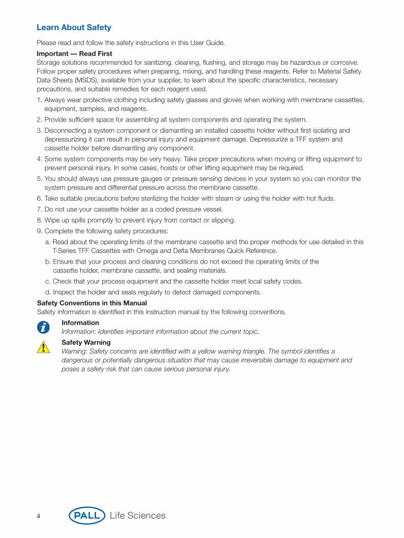
Learn About Safety
Please read and follow the safety instructions in this User Guide.
Important — Read FirstStorage solutions recommended for sanitizing, cleaning, flushing, and storage may be hazardous or corrosive.Follow proper safety procedures when preparing, mixing, and handling these reagents. Refer to Material SafetyData Sheets (MSDS), available from your supplier, to learn about the specific characteristics, necessaryprecautions, and suitable remedies for each reagent used.
1. Always wear protective clothing including safety glasses and gloves when working with membrane cassettes,equipment, samples, and reagents.
2. Provide sufficient space for assembling all system components and operating the system.
3. Disconnecting a system component or dismantling an installed cassette holder without first isolating anddepressurizing it can result in personal injury and equipment damage. Depressurize a TFF system andcassette holder before dismantling any component.
4. Some system components may be very heavy. Take proper precautions when moving or lifting equipment toprevent personal injury. In some cases, hoists or other lifting equipment may be required.
5. You should always use pressure gauges or pressure sensing devices in your system so you can monitor thesystem pressure and differential pressure across the membrane cassette.
6. Take suitable precautions before sterilizing the holder with steam or using the holder with hot fluids.
7. Do not use your cassette holder as a coded pressure vessel.
8. Wipe up spills promptly to prevent injury from contact or slipping.
9. Complete the following safety procedures:
a. Read about the operating limits of the membrane cassette and the proper methods for use detailed in thisT-Series TFF Cassettes with Omega and Delta Membranes Quick Reference.
b. Ensure that your process and cleaning conditions do not exceed the operating limits of the cassette holder, membrane cassette, and sealing materials.
c. Check that your process equipment and the cassette holder meet local safety codes.
d. Inspect the holder and seals regularly to detect damaged components.
Safety Conventions in this ManualSafety information is identified in this instruction manual by the following conventions.
InformationInformation: Identifies important information about the current topic.
Safety WarningWarning: Safety concerns are identified with a yellow warning triangle. The symbol identifies adangerous or potentially dangerous situation that may cause irreversible damage to equipment andposes a safety risk that can cause serious personal injury.

www.pall.com/biopharm 5
TFF Process Flowchart
Figure 1TFF Process Flowchart
Note: The specific steps and order of steps for processing are application specific and must beestablished by the user. Basic guidelines are shown in this abridged manual. Pall can assist withoptimizing your process.
Pre-use Conditioning Processing
Post-useConditioning
1. Installation(Page 7)
2. Flushing(Page 11)
3. Sanitization(Page 13)
2. Flushing(Page 11)
4. Normalized Water Permeability (NWP)
(Page 15)
5. Integrity Test(Page 17)
6. BufferConditioning
(Page 19)
8 and 9.Concentration
and/orDiafiltration
(Pages 23 – 26)
10. ProductRecovery(Page 27)
11. Buffer Flush(Page 29)
12. Clean InPlace (CIP)(Page 31)
2. Flushing(Page 11)
4. Normalized Water Permeability
(Page 15)
13. Storage(Page 33)
7. Optimization (Once only)
(Page 21)

6
Introduction and Key to Diagrams
This manual supplements the T-Series TFF Cassettes with Omega Membrane Care and Use Procedures(USD 2433b) and T-Series TFF Cassettes with Delta Membrane Care and Use Procedures (USD 2662). Refer torecommended flow rates and operating specifications for the Pall range of membrane cassettes. This manualcontains operating guidelines. All process steps should be validated by a qualified individual.
Figure 2Key to Diagrams
Gauge —Zero pressure
Gauge —Low pressuree.g. 0.5 barg (7 psig)
Gauge — Low pressuree.g. 1 barg (15 psig)
Gauge —Medium pressuree.g. 1.5 barg (22 psig)
Gauge —Medium pressuree.g. 2 barg (30 psig)
Pump running
Pump stopped
Valve open
Valve closed
Valve partiallyclosed/open
Pipe emptyPipe full (Water or Buffer)
Pipe closed Pipe full (Product)
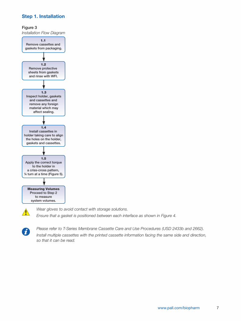
Step 1. Installation
Figure 3Installation Flow Diagram
Wear gloves to avoid contact with storage solutions.
Ensure that a gasket is positioned between each interface as shown in Figure 4.
Please refer to T-Series Membrane Cassette Care and Use Procedures (USD 2433b and 2662).
Install multiple cassettes with the printed cassette information facing the same side and direction, so that it can be read.
www.pall.com/biopharm 7
1.1 Remove cassettes and
gaskets from packaging.
1.2Remove protective sheets from gasketsand rinse with WFI.
1.3Inspect holder, gaskets
and cassettes and remove any foreignmaterial which may
affect sealing.
1.4Install cassettes in
holder taking care to alignthe holes on the holder,gaskets and cassettes.
1.5Apply the correct torque
to the holder ina criss-cross pattern,
¼ turn at a time (Figure 5).
Measuring VolumesProceed to Step 2
to measuresystem volumes.
8
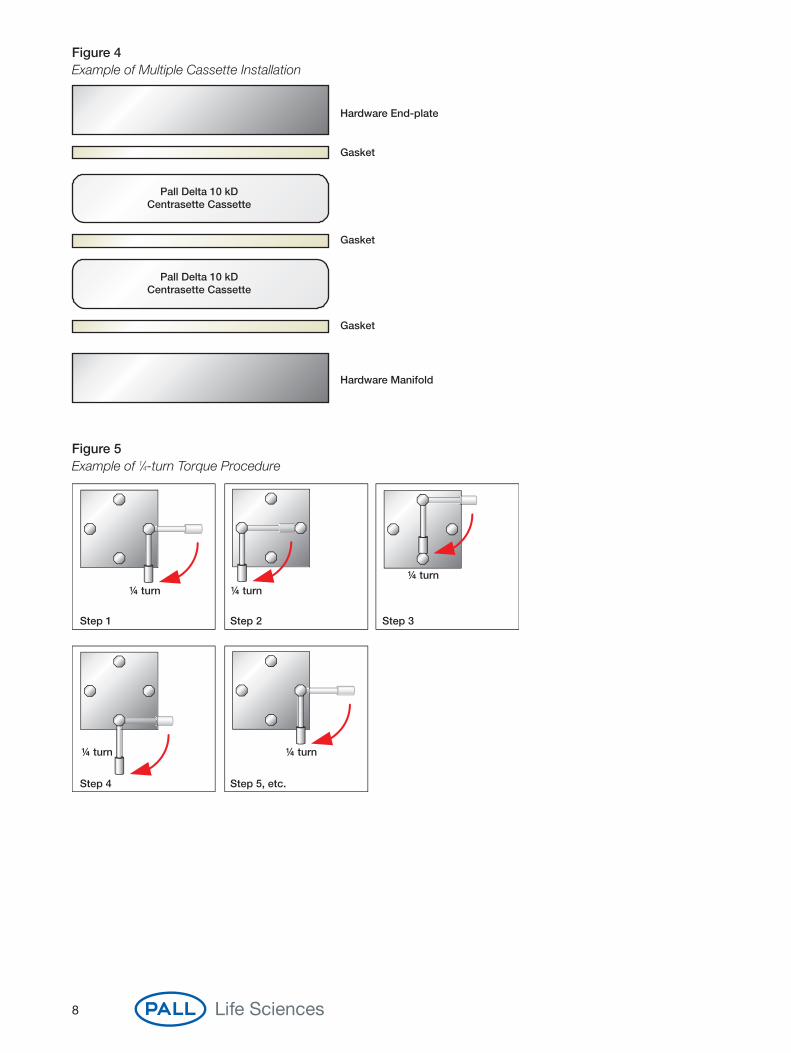
Figure 4Example of Multiple Cassette Installation
Figure 5Example of 1⁄4-turn Torque Procedure
Hardware End-plate
Hardware Manifold
Gasket
Gasket
Gasket
Pall Delta 10 kDCentrasette Cassette
Pall Delta 10 kDCentrasette Cassette
Step 1 Step 2
Step 4 Step 5, etc.
Step 3
¼ turn ¼ turn
¼ turn¼ turn
¼ turn
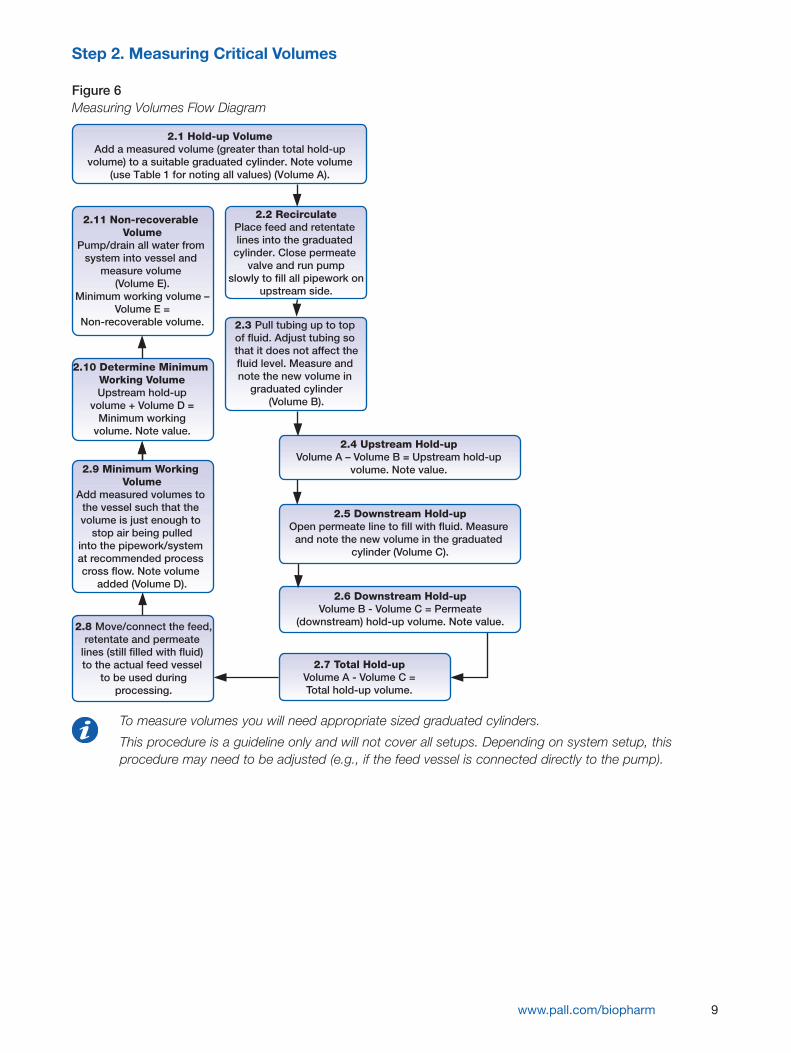
Step 2. Measuring Critical Volumes
Figure 6Measuring Volumes Flow Diagram
To measure volumes you will need appropriate sized graduated cylinders.
This procedure is a guideline only and will not cover all setups. Depending on system setup, thisprocedure may need to be adjusted (e.g., if the feed vessel is connected directly to the pump).
www.pall.com/biopharm 9
2.1 Hold-up VolumeAdd a measured volume (greater than total hold-up
volume) to a suitable graduated cylinder. Note volume(use Table 1 for noting all values) (Volume A).
2.2 RecirculatePlace feed and retentate lines into the graduated
cylinder. Close permeate valve and run pump
slowly to fill all pipework onupstream side.
2.11 Non-recoverable Volume
Pump/drain all water from system into vessel and
measure volume (Volume E).
Minimum working volume – Volume E =
Non-recoverable volume. 2.3 Pull tubing up to top of fluid. Adjust tubing so that it does not affect thefluid level. Measure and note the new volume in
graduated cylinder(Volume B).
2.10 Determine Minimum Working VolumeUpstream hold-up
volume + Volume D =Minimum working
volume. Note value.2.4 Upstream Hold-up
Volume A – Volume B = Upstream hold-upvolume. Note value.2.9 Minimum Working
VolumeAdd measured volumes to
the vessel such that the volume is just enough to
stop air being pulledinto the pipework/system at recommended process cross flow. Note volume
added (Volume D).
2.5 Downstream Hold-upOpen permeate line to fill with fluid. Measure and note the new volume in the graduated
cylinder (Volume C).
2.8 Move/connect the feed,retentate and permeate
lines (still filled with fluid) to the actual feed vessel
to be used duringprocessing.
2.6 Downstream Hold-upVolume B - Volume C = Permeate
(downstream) hold-up volume. Note value.
2.7 Total Hold-upVolume A - Volume C =Total hold-up volume.

10
Figure 7 Figure 8Setup for Hold-up Volume — Volume A (Step 2.1) Volume B (Step 2.3)
Figure 9 Figure 10Volume C (Step 2.5) Minimum Working Volume at Process CFF (Step 2.9)
Table 1Measured Volumes
Volume Tag Description Measured/Noted Value
Volume A Initial Volume
Volume B Vessel Volume after Step 2.3
Upstream Hold-up Volume (Volume A – Volume B)
Volume C Vessel Volume after Step 2.5
Permeate Hold-up Volume (Volume B – Volume C)
Total Hold-up Volume (Volume A – Volume C)
Volume D Volume added during Step 2.9
Minimum Working Volume Upstream Hold-up Volume + Volume D
Volume E Volume recovered during Step 2.11
Non-recoverable Volume Minimum Working Volume – Volume E
RetentatePermeate
Volume A
Feed
Pump
RetentatePermeate
Volume B
Feed
Pump
RetentatePermeate
Volume C
Feed
Pump
RetentatePermeate
Volume E
Feed
Pump
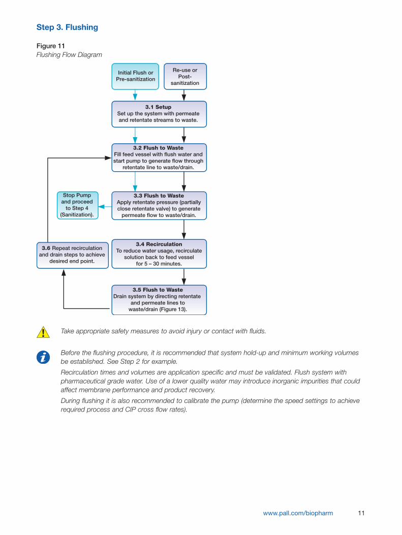
Step 3. Flushing
Figure 11Flushing Flow Diagram
Take appropriate safety measures to avoid injury or contact with fluids.
Before the flushing procedure, it is recommended that system hold-up and minimum working volumesbe established. See Step 2 for example.
Recirculation times and volumes are application specific and must be validated. Flush system withpharmaceutical grade water. Use of a lower quality water may introduce inorganic impurities that couldaffect membrane performance and product recovery.
During flushing it is also recommended to calibrate the pump (determine the speed settings to achieverequired process and CIP cross flow rates).
www.pall.com/biopharm 11
Initial Flush orPre-sanitization
Re-use orPost-
sanitization
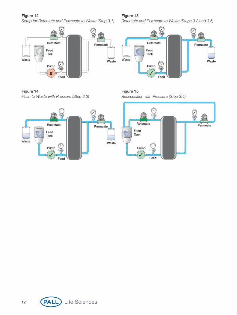
3.1 SetupSet up the system with permeateand retentate streams to waste.
3.2 Flush to WasteFill feed vessel with flush water andstart pump to generate flow through
retentate line to waste/drain.
Stop Pumpand proceed
to Step 4(Sanitization).
3.3 Flush to WasteApply retentate pressure (partiallyclose retentate valve) to generate
permeate flow to waste/drain.
3.6 Repeat recirculationand drain steps to achieve
desired end point.
3.4 RecirculationTo reduce water usage, recirculate
solution back to feed vesselfor 5 – 30 minutes.
3.5 Flush to WasteDrain system by directing retentate
and permeate lines towaste/drain (Figure 13).
12
Figure 12 Figure 13Setup for Retentate and Permeate to Waste (Step 3.1) Retentate and Permeate to Waste (Steps 3.2 and 3.5)
Figure 14 Figure 15Flush to Waste with Pressure (Step 3.3) Recirculation with Pressure (Step 3.4)
Retentate Permeate
Feed Tank
Waste Waste
Feed
Pump
Waste
Retentate Permeate
Feed Tank
Waste
Feed
Pump
Waste
Retentate Permeate
Feed Tank
Waste
Feed
Pump
Retentate Permeate
Feed Tank
Feed
Pump
Step 4. Sanitization
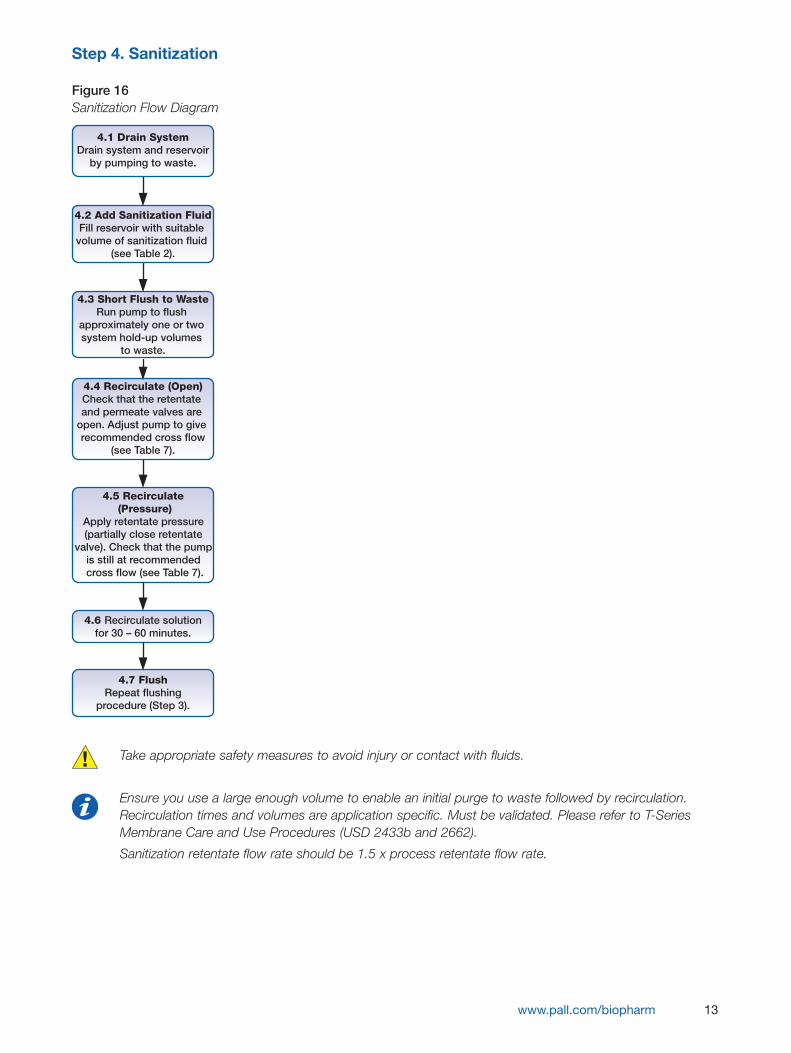
Figure 16Sanitization Flow Diagram
Take appropriate safety measures to avoid injury or contact with fluids.
Ensure you use a large enough volume to enable an initial purge to waste followed by recirculation.Recirculation times and volumes are application specific. Must be validated. Please refer to T-SeriesMembrane Care and Use Procedures (USD 2433b and 2662).
Sanitization retentate flow rate should be 1.5 x process retentate flow rate.
www.pall.com/biopharm 13
4.7 FlushRepeat flushing
procedure (Step 3).
4.1 Drain SystemDrain system and reservoir
by pumping to waste.
4.2 Add Sanitization FluidFill reservoir with suitable
volume of sanitization fluid (see Table 2).
4.3 Short Flush to WasteRun pump to flush
approximately one or two system hold-up volumes
to waste.
4.5 Recirculate (Pressure)
Apply retentate pressure (partially close retentate
valve). Check that the pump is still at recommended cross flow (see Table 7).
4.4 Recirculate (Open)Check that the retentate and permeate valves are
open. Adjust pump to give recommended cross flow
(see Table 7).
4.6 Recirculate solutionfor 30 – 60 minutes.
14
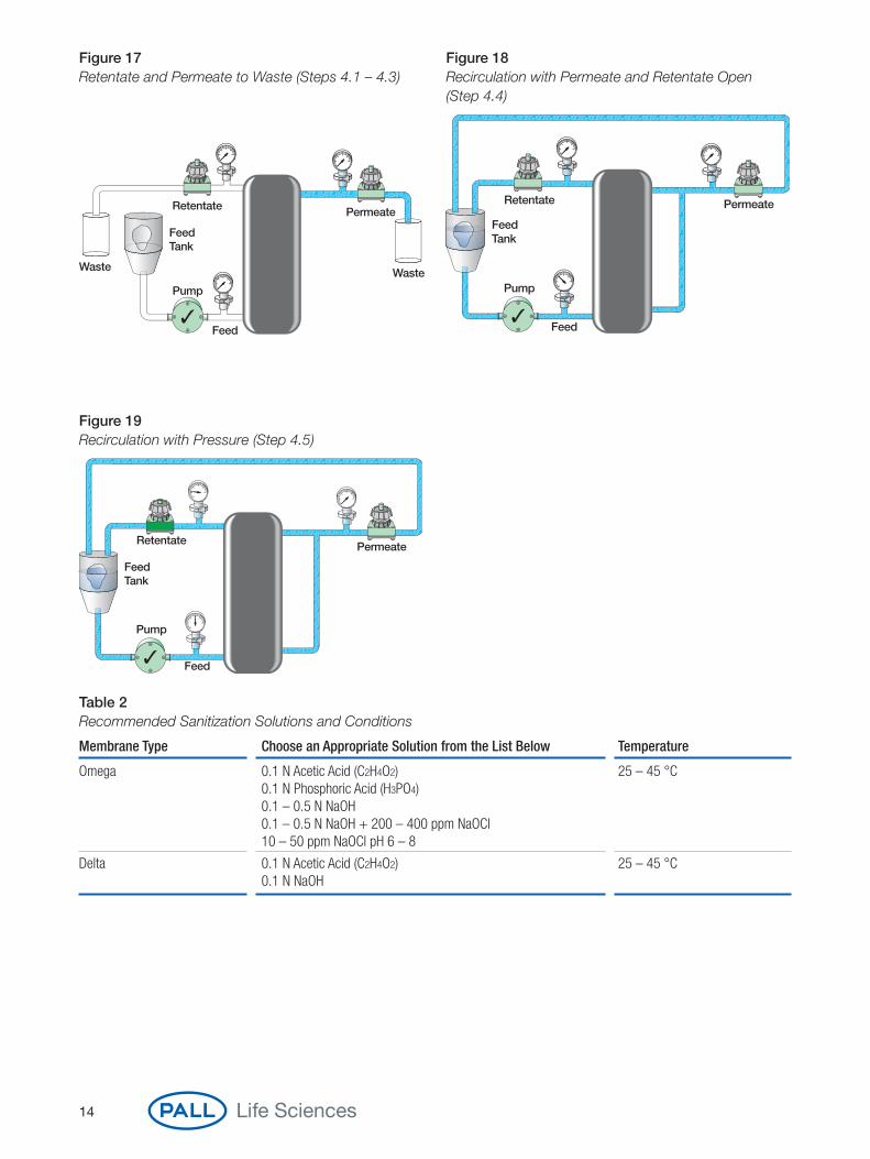
Figure 17 Figure 18Retentate and Permeate to Waste (Steps 4.1 – 4.3) Recirculation with Permeate and Retentate Open
(Step 4.4)
Figure 19Recirculation with Pressure (Step 4.5)
Retentate Permeate
Feed Tank
Waste Waste
Feed
Pump
Retentate Permeate
Feed Tank
Feed
Pump
Retentate Permeate
Feed Tank
Feed
Pump
Table 2Recommended Sanitization Solutions and Conditions
Membrane Type Choose an Appropriate Solution from the List Below Temperature
Omega 0.1 N Acetic Acid (C2H4O2) 25 – 45 °C0.1 N Phosphoric Acid (H3PO4)0.1 – 0.5 N NaOH 0.1 – 0.5 N NaOH + 200 – 400 ppm NaOCl 10 – 50 ppm NaOCl pH 6 – 8
Delta 0.1 N Acetic Acid (C2H4O2) 25 – 45 °C0.1 N NaOH

Step 5. Normalized Water Permeability (NWP)
Figure 20Normalized Water Permeability (NWP) Flow Diagram
Take appropriate safety measures to avoid injury or contact with fluids.
Water quality should be Water For Injection (WFI) or at a minimum 0.2 µm filtered DI.
The initial NWP20°C of the cassette is essential to calculate because it is used as the basis to determinemembrane recovery.
Be sure to use calibrated equipment that is accurate in the measurement range.
www.pall.com/biopharm 15
5.1 With system in recirculation, fill feed vessel withwater and increase pump speed to achieve recommended
cross flow rate (Page 35).
5.2 Remove Air Partially close the retentate valve to increase feed
pressure then open immediately. Repeat several times. Set pump speed to zero.
5.3 Set Initial TMP ValueFully close the retentate valve, then increase pump
speed slowly to obtain desired TMP.
5.4 Measure Permeate Flow Open, then close the retentate valve to release trapped air.
Measure the permeate flow rate (typically mL/min) andconvert to LMH. Measure water temperature.
5.5 Plot Permeate Flux vs. TMP (Figure 26).
5.6 Increase TMP Value(See Typical TMP for typical values.) Increase pump
speed slowly to increase TMP. Repeat steps 5.4 – 5.5.
5.7 Repeat Step 5.6 at next TMP.
5.8 Determine NWP at a single point easily measured on the plot. This can be used as a quick reference for future
(Figure 26).�Typical TMP Value: barg (psig)
Ultrafiltration: 0.5 – 1.5 (7 – 22)
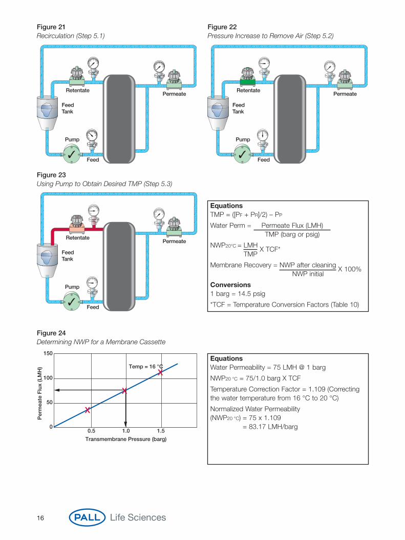
Figure 24Determining NWP for a Membrane Cassette
Per
mea
te F
lux
(LM
H)
150
100
50
00.5 1.0 1.5
Transmembrane Pressure (barg)
Temp = 16 °C
16
Figure 21 Figure 22Recirculation (Step 5.1) Pressure Increase to Remove Air (Step 5.2)
Figure 23Using Pump to Obtain Desired TMP (Step 5.3)
RetentatePermeate
Feed Tank
Feed
Pump
RetentatePermeate
Feed Tank
Feed
Pump
RetentatePermeate
Feed Tank
Feed
Pump
EquationsTMP = ([PF + PR]/2) – PP
Water Perm = Permeate Flux (LMH)TMP (barg or psig)
NWP20°C = LMH X TCF*
TMP
Membrane Recovery = NWP after cleaning X 100%
NWP initial
Conversions 1 barg = 14.5 psig
*TCF = Temperature Conversion Factors (Table 10)
EquationsWater Permeability = 75 LMH @ 1 barg
NWP20 °C = 75/1.0 barg X TCF
Temperature Correction Factor = 1.109 (Correctingthe water temperature from 16 °C to 20 °C)
Normalized Water Permeability (NWP20 °C) = 75 x 1.109
= 83.17 LMH/barg
Step 6. Integrity Testing
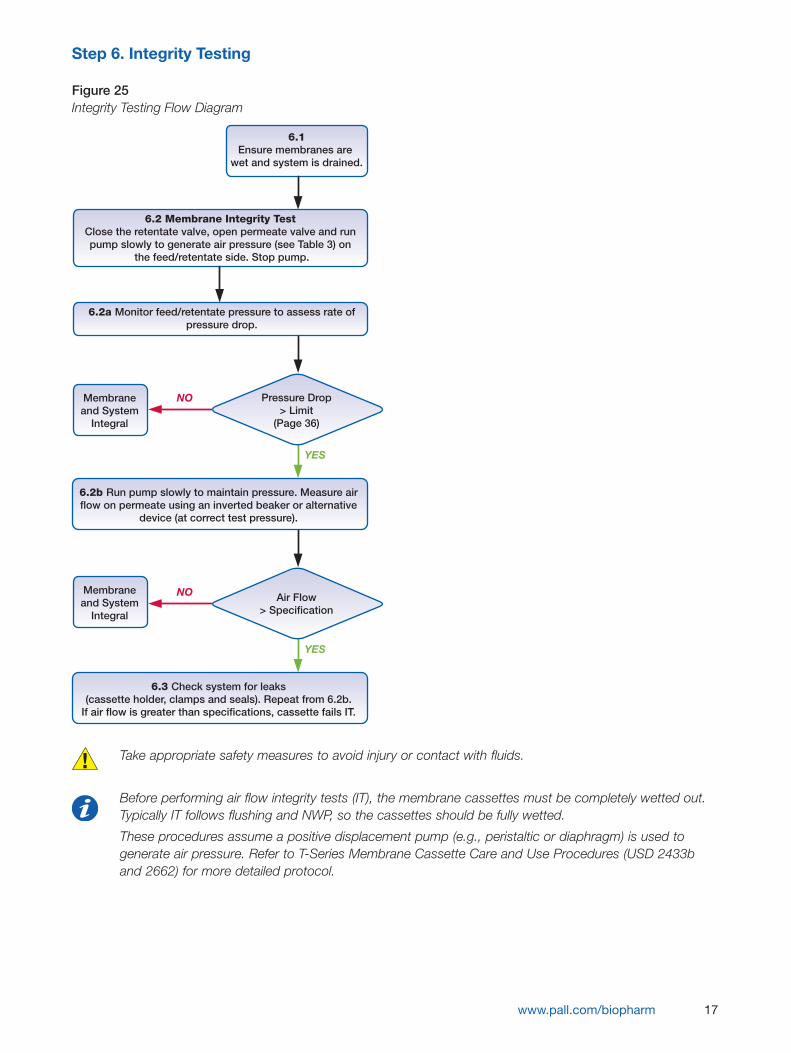
Figure 25Integrity Testing Flow Diagram
Take appropriate safety measures to avoid injury or contact with fluids.
Before performing air flow integrity tests (IT), the membrane cassettes must be completely wetted out.Typically IT follows flushing and NWP, so the cassettes should be fully wetted.
These procedures assume a positive displacement pump (e.g., peristaltic or diaphragm) is used togenerate air pressure. Refer to T-Series Membrane Cassette Care and Use Procedures (USD 2433band 2662) for more detailed protocol.
www.pall.com/biopharm 17
6.1Ensure membranes are
wet and system is drained.
6.2 Membrane Integrity Test Close the retentate valve, open permeate valve and run pump slowly to generate air pressure (see Table 3) on
the feed/retentate side. Stop pump.
6.2a Monitor feed/retentate pressure to assess rate ofpressure drop.
Pressure Drop> Limit
(Page 36)
YES
NO
YES
NO Air Flow> Specification
6.2b Run pump slowly to maintain pressure. Measure airflow on permeate using an inverted beaker or alternative
device (at correct test pressure).
6.3 Check system for leaks(cassette holder, clamps and seals). Repeat from 6.2b.
If air flow is greater than specifications, cassette fails IT.
Membraneand System
Integral
Membraneand System
Integral

18
Figure 26 Figure 27Membrane Integrity Test – Generating Air Pressure (6.2) Membrane Integrity Test – Monitoring Air Pressure (6.2a)
Figure 28Measuring Air Flow with Inverted Beaker (6.2b)
RetentatePermeate
Feed Tank
GraduatedVessel
Feed
Pump
RetentatePermeate
Feed Tank
GraduatedVessel
Feed
Pump
RetentatePermeate
Feed Tank
GraduatedVessel
Feed
Pump
Limit (guideline) for pressure drop: 200 mbarg/min or 3 psig/min. (Note: this is a guideline only. Direct measurement of diffusive flow should be used where necessary.)
Table 3Recommended Air Flow Test Pressure and Specifications
Allowable Air Forward Flow Rate Membrane NMWC* Test Pressure per Unit of Membrane
≤ 300 kD 2.0 barg (30 psig) < 1600 sccm/m2 (< 150 sccm/ft2)
*Nominal Molecular Weight Cutoff
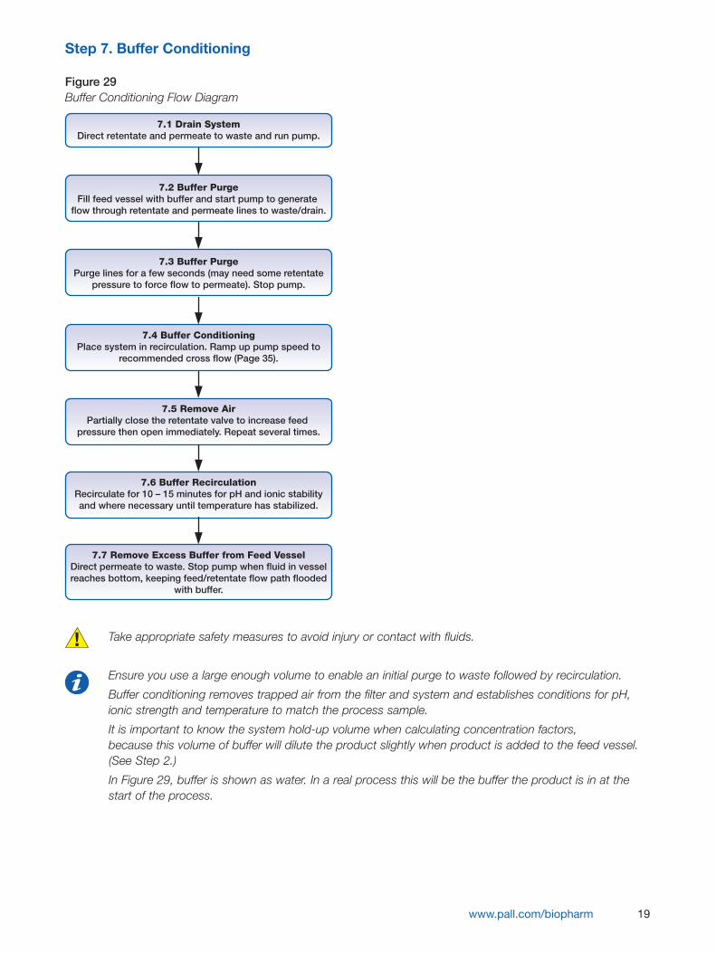
Step 7. Buffer Conditioning
Figure 29Buffer Conditioning Flow Diagram
Take appropriate safety measures to avoid injury or contact with fluids.
Ensure you use a large enough volume to enable an initial purge to waste followed by recirculation.
Buffer conditioning removes trapped air from the filter and system and establishes conditions for pH,ionic strength and temperature to match the process sample.
It is important to know the system hold-up volume when calculating concentration factors, because this volume of buffer will dilute the product slightly when product is added to the feed vessel.(See Step 2.)
In Figure 29, buffer is shown as water. In a real process this will be the buffer the product is in at thestart of the process.
www.pall.com/biopharm 19
7.1 Drain SystemDirect retentate and permeate to waste and run pump.
7.2 Buffer PurgeFill feed vessel with buffer and start pump to generate
flow through retentate and permeate lines to waste/drain.
7.3 Buffer PurgePurge lines for a few seconds (may need some retentate
pressure to force flow to permeate). Stop pump.
7.4 Buffer ConditioningPlace system in recirculation. Ramp up pump speed to
recommended cross flow (Page 35).
7.5 Remove AirPartially close the retentate valve to increase feed
pressure then open immediately. Repeat several times.
7.6 Buffer RecirculationRecirculate for 10 – 15 minutes for pH and ionic stabilityand where necessary until temperature has stabilized.
7.7 Remove Excess Buffer from Feed VesselDirect permeate to waste. Stop pump when fluid in vesselreaches bottom, keeping feed/retentate flow path flooded
with buffer.
20
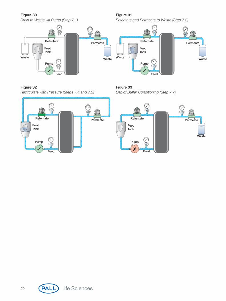
Figure 30 Figure 31Drain to Waste via Pump (Step 7.1) Retentate and Permeate to Waste (Step 7.2)
Figure 32 Figure 33Recirculate with Pressure (Steps 7.4 and 7.5) End of Buffer Conditioning (Step 7.7)
Retentate
Feed Tank
Waste
Feed
Pump
Permeate
Waste
Retentate
Feed Tank
Waste
Feed
Pump
Permeate
Waste
Retentate Permeate
Feed Tank
Feed
Pump
Retentate
Feed Tank
Feed
Pump
Permeate
Waste
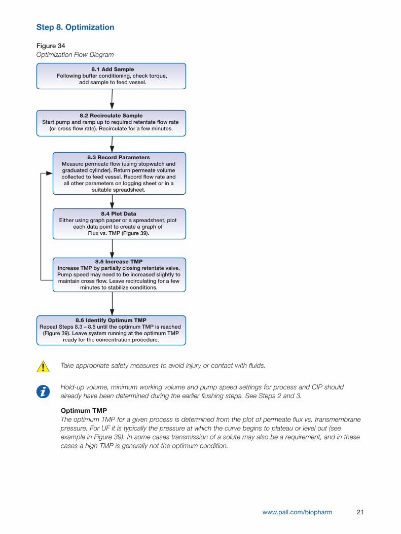
Step 8. Optimization
Figure 34Optimization Flow Diagram
Take appropriate safety measures to avoid injury or contact with fluids.
Hold-up volume, minimum working volume and pump speed settings for process and CIP shouldalready have been determined during the earlier flushing steps. See Steps 2 and 3.
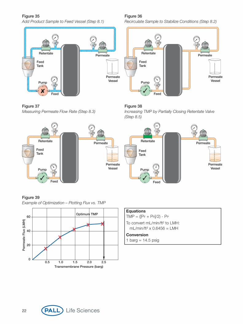
Optimum TMPThe optimum TMP for a given process is determined from the plot of permeate flux vs. transmembranepressure. For UF it is typically the pressure at which the curve begins to plateau or level out (seeexample in Figure 39). In some cases transmission of a solute may also be a requirement, and in thesecases a high TMP is generally not the optimum condition.
www.pall.com/biopharm 21
8.1 Add SampleFollowing buffer conditioning, check torque,
add sample to feed vessel.
8.2 Recirculate SampleStart pump and ramp up to required retentate flow rate
(or cross flow rate). Recirculate for a few minutes.
8.3 Record ParametersMeasure permeate flow (using stopwatch andgraduated cylinder). Return permeate volumecollected to feed vessel. Record flow rate andall other parameters on logging sheet or in a
suitable spreadsheet.
8.4 Plot DataEither using graph paper or a spreadsheet, plot
each data point to create a graph of Flux vs. TMP (Figure 39).
8.5 Increase TMPIncrease TMP by partially closing retentate valve.Pump speed may need to be increased slightly tomaintain cross flow. Leave recirculating for a few
minutes to stabilize conditions.
8.6 Identify Optimum TMPRepeat Steps 8.3 – 8.5 until the optimum TMP is reached
(Figure 39). Leave system running at the optimum TMPready for the concentration procedure.
22
Figure 35 Figure 36Add Product Sample to Feed Vessel (Step 8.1) Recirculate Sample to Stabilize Conditions (Step 8.2)
Figure 37 Figure 38Measuring Permeate Flow Rate (Step 8.3) Increasing TMP by Partially Closing Retentate Valve
(Step 8.5)
RetentatePermeate
Feed Tank
PermeateVessel
Feed
Pump
RetentatePermeate
Feed Tank
PermeateVessel
Feed
Pump
RetentatePermeate
Feed Tank
Feed
Pump
PermeateVessel
RetentatePermeate
Feed Tank
Feed
Pump
PermeateVessel
Figure 39Example of Optimization – Plotting Flux vs. TMP
0.5 1.0 1.5 2.0 2.5Transmembrane Pressure (barg)
Optimum TMP
Per
mea
te F
lux
(LM
H)
60
40
20
0
EquationsTMP = ([PF + PR]/2) - PP
To convert mL/min/ft² to LMH:mL/min/ft² x 0.6456 = LMH
Conversion1 barg = 14.5 psig
Step 9. Concentration
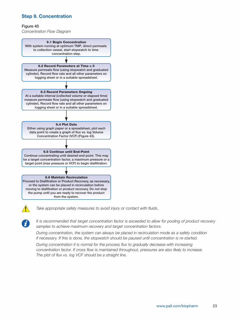
Take appropriate safety measures to avoid injury or contact with fluids.
It is recommended that target concentration factor is exceeded to allow for pooling of product recoverysamples to achieve maximum recovery and target concentration factors.
During concentration, the system can always be placed in recirculation mode as a safety conditionif necessary. If this is done, the stopwatch should be paused until concentration is re-started.
During concentration it is normal for the process flux to gradually decrease with increasingconcentration factor. If cross flow is maintained throughout, pressures are also likely to increase.The plot of flux vs. log VCF should be a straight line.
www.pall.com/biopharm 23
9.1 Begin ConcentrationWith system running at optimum TMP, direct permeate
to collection vessel, start stopwatch to time concentration step.
9.2 Record Parameters at Time = 0Measure permeate flow (using stopwatch and graduatedcylinder). Record flow rate and all other parameters on
logging sheet or in a suitable spreadsheet.
9.3 Record Parameters OngoingAt a suitable interval (collected volume or elapsed time)measure permeate flow (using stopwatch and graduatedcylinder). Record flow rate and all other parameters on
logging sheet or in a suitable spreadsheet.
9.4 Plot DataEither using graph paper or a spreadsheet, plot each
data point to create a graph of flux vs. log VolumeConcentration Factor (VCF) (Figure 43).
9.5 Continue until End-PointContinue concentrating until desired end-point. This may
be a target concentration factor, a maximum pressure or atarget point (max pressure or VCF) to begin diafiltration.
9.6 Maintain RecirculationProceed to Diafiltration or Product Recovery, as necessary,
or the system can be placed in recirculation beforemoving to diafiltration or product recovery. Do not stop
the pump until you are ready to recover the productfrom the system.
Figure 40Concentration Flow Diagram
24
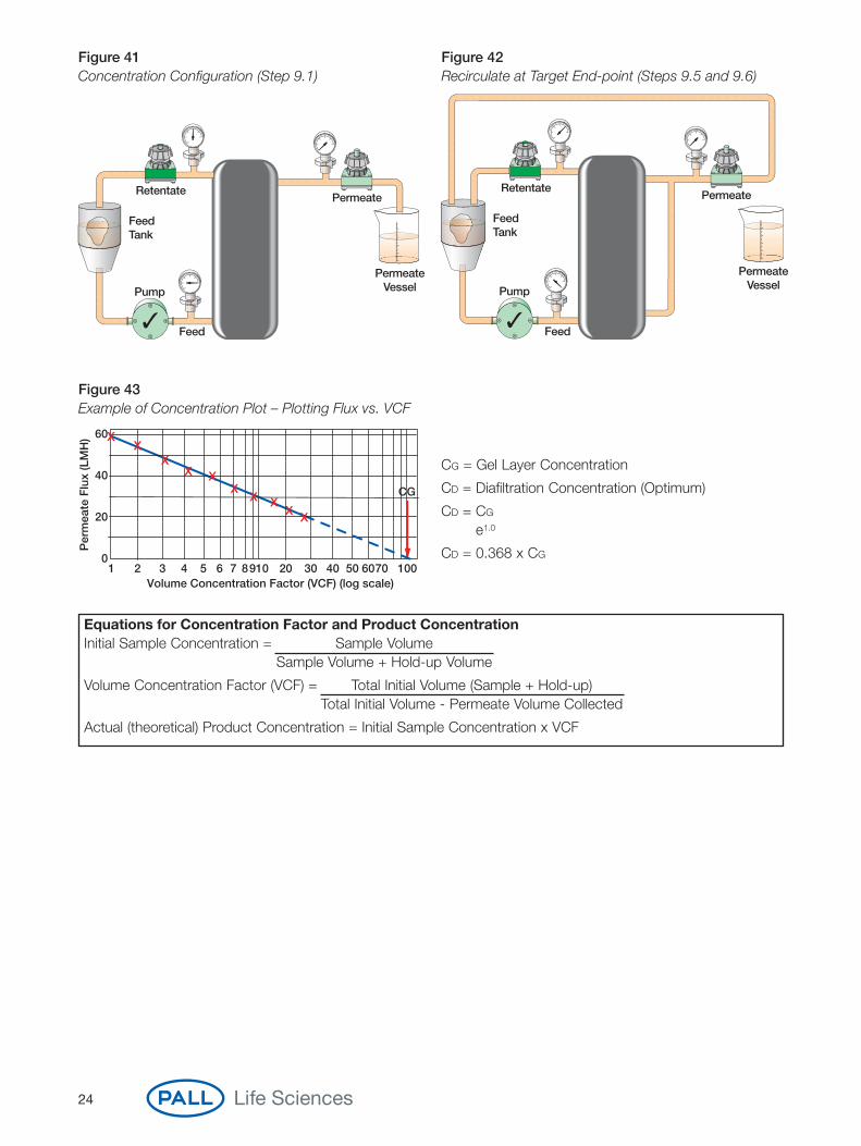
Figure 41 Figure 42Concentration Configuration (Step 9.1) Recirculate at Target End-point (Steps 9.5 and 9.6)
60
40
20
01 2 3 4 5 6 7 8 9 10 20 30 40 50 60 70 100
Volume Concentration Factor (VCF) (log scale)
CG
Per
mea
te F
lux
(LM
H)
RetentatePermeate
Feed Tank
PermeateVessel
Feed
Pump
RetentatePermeate
Feed Tank
Feed
Pump
PermeateVessel
CG = Gel Layer Concentration
CD = Diafiltration Concentration (Optimum)
CD = CG
e1.0
CD = 0.368 x CG
Equations for Concentration Factor and Product ConcentrationInitial Sample Concentration = Sample Volume
Sample Volume + Hold-up Volume
Volume Concentration Factor (VCF) = Total Initial Volume (Sample + Hold-up)Total Initial Volume - Permeate Volume Collected
Actual (theoretical) Product Concentration = Initial Sample Concentration x VCF
Figure 43Example of Concentration Plot – Plotting Flux vs. VCF
Step 10. Diafiltration
Figure 44Diafiltration Flow Diagram
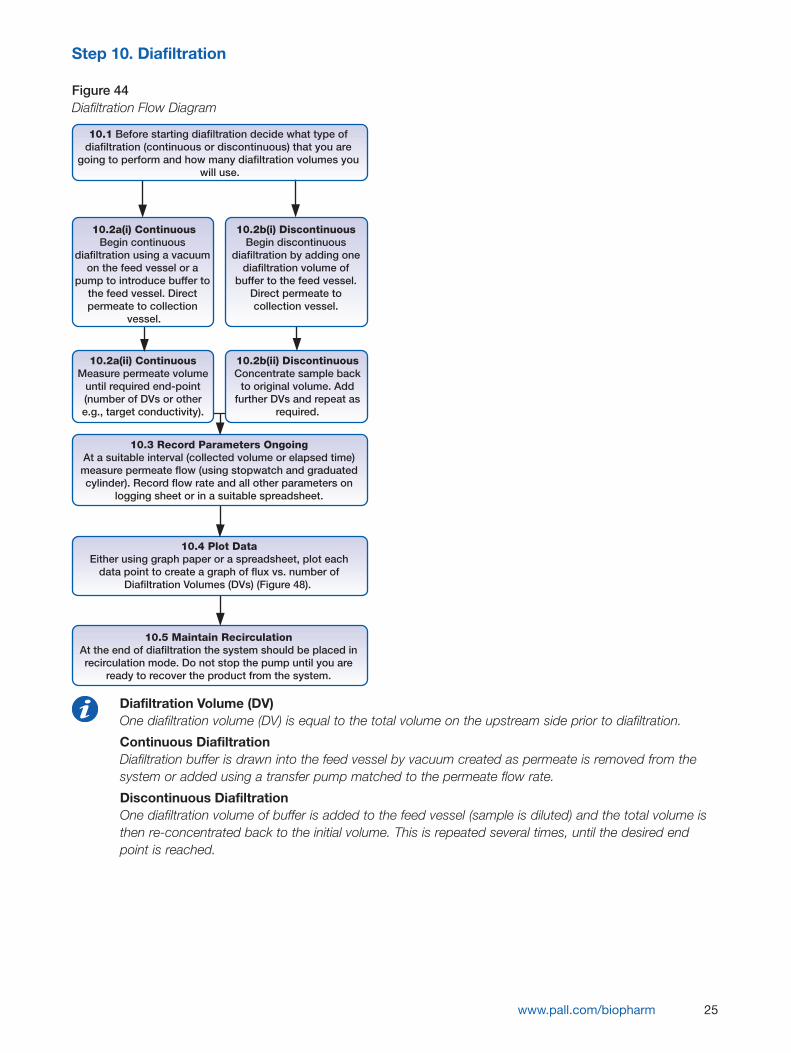
Diafiltration Volume (DV) One diafiltration volume (DV) is equal to the total volume on the upstream side prior to diafiltration.
Continuous Diafiltration Diafiltration buffer is drawn into the feed vessel by vacuum created as permeate is removed from thesystem or added using a transfer pump matched to the permeate flow rate.
Discontinuous DiafiltrationOne diafiltration volume of buffer is added to the feed vessel (sample is diluted) and the total volume isthen re-concentrated back to the initial volume. This is repeated several times, until the desired endpoint is reached.
www.pall.com/biopharm 25
10.1 Before starting diafiltration decide what type of diafiltration (continuous or discontinuous) that you are
going to perform and how many diafiltration volumes you will use.
10.2a(i) ContinuousBegin continuous
diafiltration using a vacuum on the feed vessel or a
pump to introduce buffer to the feed vessel. Direct permeate to collection
vessel.
10.2b(i) DiscontinuousBegin discontinuous
diafiltration by adding onediafiltration volume of
buffer to the feed vessel.Direct permeate tocollection vessel.
10.2a(ii) ContinuousMeasure permeate volume
until required end-point(number of DVs or othere.g., target conductivity).
10.2b(ii) DiscontinuousConcentrate sample back
to original volume. Addfurther DVs and repeat as
required.
10.3 Record Parameters OngoingAt a suitable interval (collected volume or elapsed time)measure permeate flow (using stopwatch and graduatedcylinder). Record flow rate and all other parameters on
logging sheet or in a suitable spreadsheet.
10.4 Plot DataEither using graph paper or a spreadsheet, plot each
data point to create a graph of flux vs. number ofDiafiltration Volumes (DVs) (Figure 48).
10.5 Maintain RecirculationAt the end of diafiltration the system should be placed inrecirculation mode. Do not stop the pump until you are
ready to recover the product from the system.

26
Figure 45 Figure 46Continuous Diafiltration (Step 10.2a) Discontinuous Diafiltration, Adding 1 DV (Step 10.2b)
Figure 47Recirculate at Target End-point (Step 10.5)
Retentate
BufferTank
Permeate
Feed Tank
PermeateVessel
Feed
Pump
Retentate
BufferTank
Permeate
Feed Tank
1 DV
PermeateVessel
Feed
Pump
Retentate Permeate
Feed Tank
Feed
PumpPermeate
Vessel
Note: Some form of mixing in the feed vessel will typically be required during diafiltration to ensure theadded buffer mixes thoroughly with the product.
60
40
20
01 2 3 4 5
Number of Diafiltration Volumes (DVs)
Per
mea
te F
lux
(LM
H)
Figure 48Example of Diafiltration – Plotting Flux vs. DVs

Step 11. Product Recovery
Figure 49Product Recovery Flow Diagram
The procedure shown is an example only. Product recovery should be optimized for each process.
To maximize product yield at the desired final concentration, it is recommended that targetconcentration factor is exceeded to allow for pooling of product recovery samples to achieve maximumrecovery and target concentration factors.
www.pall.com/biopharm 27
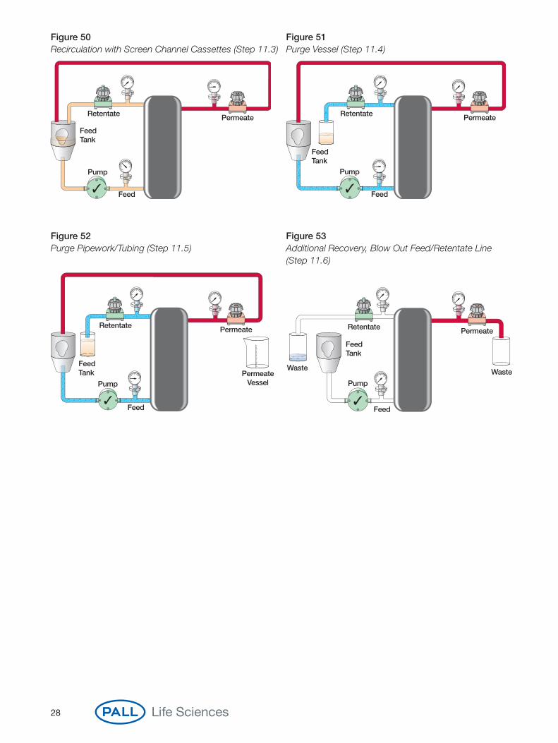
11.1 Maximize RecoveryWith system in recirculation from previous step (either
concentration or diafiltration), open the retentate valve fully.
11.2 Close PermeateClose the permeate valve fully.
11.3 Adjust Cross FlowAdjust pump speed to achieve desired process cross flow.
Recirculate for 10 minutes.
11.4 Purge VesselStop pump. Direct retentate to collection vessel. Run
pump slowly to purge volume from feed vessel into the collection vessel (pipework/tubing remains full).
Stop pump.
11.5 Purge Pipework/TubingAdd one upstream hold-up volume of buffer to feed vessel.
Run pump slowly until vessel is just empty (hold-up volume purge). Stop pump.
11.6 Additional RecoveryIntroduce buffer into feed vessel such that total system
volume = minimum working volume. Repeat steps 11.3 to 11.5. Use pump to air purge lines. Collect recovered
sample in a separate container.
28
Figure 50 Figure 51Recirculation with Screen Channel Cassettes (Step 11.3) Purge Vessel (Step 11.4)
Figure 52 Figure 53Purge Pipework/Tubing (Step 11.5) Additional Recovery, Blow Out Feed/Retentate Line
(Step 11.6)
Retentate Permeate
Feed Tank
Feed
PumpPermeate
Vessel
Retentate
Feed Tank
Waste
Feed
Pump
Permeate
Waste
Retentate Permeate
Feed Tank
Feed
Pump
Retentate Permeate
Feed Tank
Feed
Pump

Step 12. Buffer Flush
Figure 54Buffer Flush Flow Diagram
Take appropriate safety measures to avoid injury or contact with fluids.
Buffer flush is recommended to remove foulants that can be easily washed out prior to introducingchemicals. Alternatively, users can go straight to Step 13, CIP.
Recirculation times and volumes are application specific. These must be validated.
www.pall.com/biopharm 29
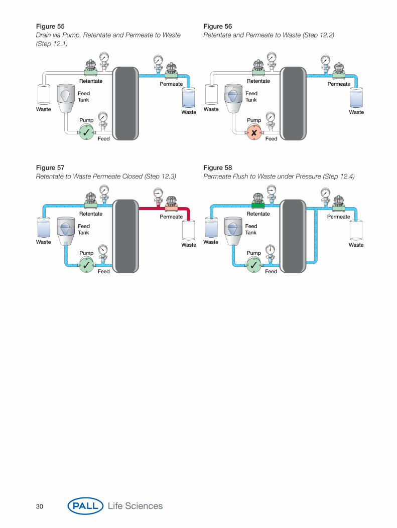
12.1Drain the vessel by running
the pump and directing retentate and permeate to waste. Stop the pump.
12.2Introduce a suitable
volume of buffer or WFI into feed vessel to allow
flushing to waste through the retentate and permeate lines.
12.3With permeate closed, pump buffer through retentate to waste.
Stop pump afterapproximately 2 total hold-up volumes have
passed to waste.
12.4Open permeate valve. Start pump and apply retentate pressure to
purge the permeate line to waste.
12.5Drain system (Figure 55)
and ready for Step 13.
30
Figure 55 Figure 56Drain via Pump, Retentate and Permeate to Waste Retentate and Permeate to Waste (Step 12.2)(Step 12.1)
Figure 57 Figure 58Retentate to Waste Permeate Closed (Step 12.3) Permeate Flush to Waste under Pressure (Step 12.4)
Retentate
Feed Tank
Waste
Feed
Pump
Permeate
Waste
Retentate
Feed Tank
Waste
Feed
Pump
Permeate
Waste
Retentate
Feed Tank
Waste
Feed
Pump
Permeate
Waste
Retentate
Feed Tank
Waste
Feed
Pump
Permeate
Waste
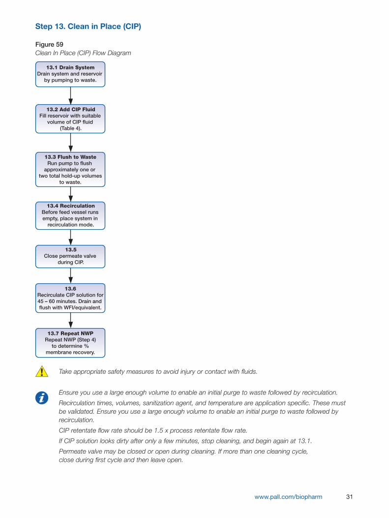
Step 13. Clean in Place (CIP)
Figure 59Clean In Place (CIP) Flow Diagram
Take appropriate safety measures to avoid injury or contact with fluids.
Ensure you use a large enough volume to enable an initial purge to waste followed by recirculation.
Recirculation times, volumes, sanitization agent, and temperature are application specific. These mustbe validated. Ensure you use a large enough volume to enable an initial purge to waste followed byrecirculation.
CIP retentate flow rate should be 1.5 x process retentate flow rate.
If CIP solution looks dirty after only a few minutes, stop cleaning, and begin again at 13.1.
Permeate valve may be closed or open during cleaning. If more than one cleaning cycle, close during first cycle and then leave open.
www.pall.com/biopharm 31
13.1 Drain SystemDrain system and reservoir
by pumping to waste.
13.2 Add CIP FluidFill reservoir with suitable
volume of CIP fluid (Table 4).
13.3 Flush to WasteRun pump to flush
approximately one or two total hold-up volumes
to waste.
13.4 RecirculationBefore feed vessel runs empty, place system in
recirculation mode.
13.5Close permeate valve
during CIP.
13.6Recirculate CIP solution for45 – 60 minutes. Drain and flush with WFI/equivalent.
13.7 Repeat NWPRepeat NWP (Step 4)
to determine %membrane recovery.

32
Figure 60 Figure 61Retentate and Permeate to Waste (Steps 13.1 and 13.3) Recirculation with Permeate Open (Step 13.4)
Figure 62 Figure 63Recirculation with Permeate Closed (Step 13.5) Recirculation with Permeate Open, Retentate Partially
Closed (Step 13.5)
Retentate Permeate
Feed Tank
Feed
Pump
Retentate Permeate
Feed Tank
Feed
Pump
Retentate
Feed Tank
Waste
Feed
Pump
Permeate
Waste
Retentate Permeate
Feed Tank
Feed
Pump
Table 4Recommended CIP Solutions and Conditions
Membrane Type Choose Suitable CIP Solution Temperature
Omega 0.1 – 0.5 N NaOH0.1 – 0.5 N NaOH + 200 – 400 ppm NaOCl 25 – 45 °C
Delta 0.1 N - 0.25 N NaOH 25 – 45 °C
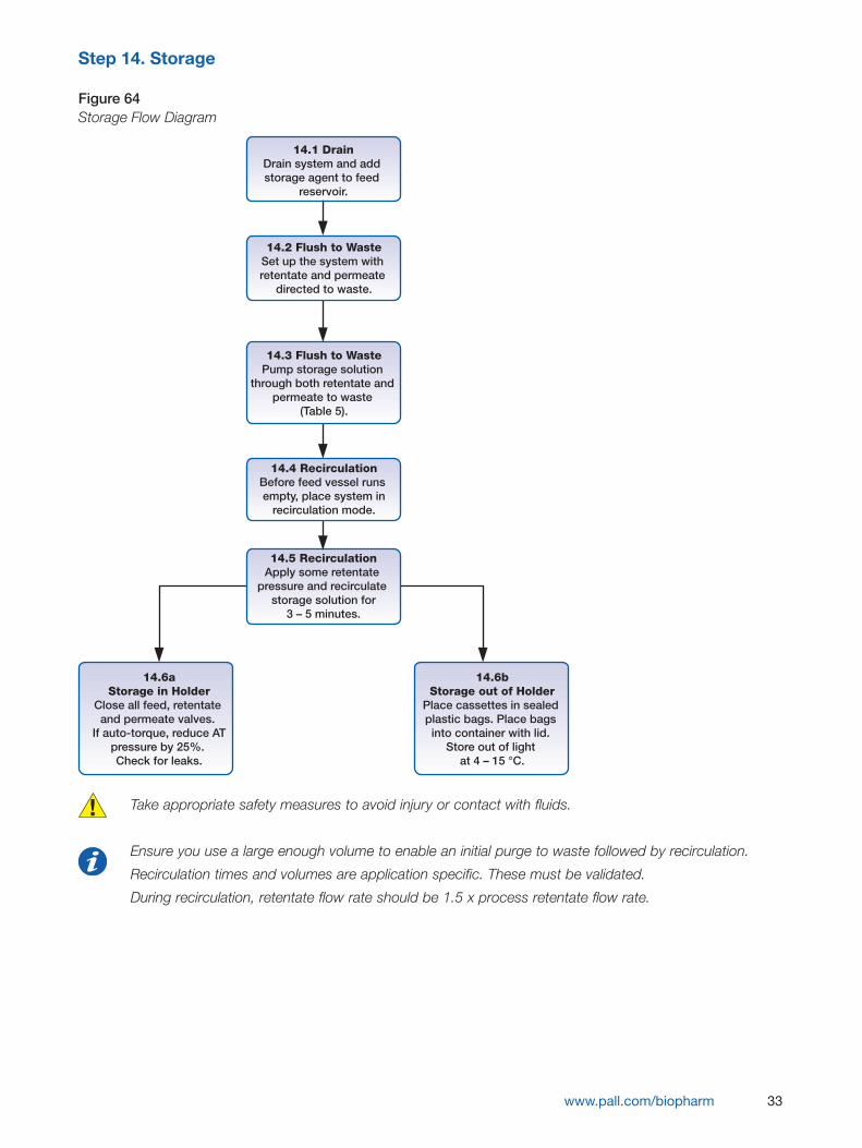
Step 14. Storage
Figure 64Storage Flow Diagram
Take appropriate safety measures to avoid injury or contact with fluids.
Ensure you use a large enough volume to enable an initial purge to waste followed by recirculation.
Recirculation times and volumes are application specific. These must be validated.
During recirculation, retentate flow rate should be 1.5 x process retentate flow rate.
www.pall.com/biopharm 33
14.1 DrainDrain system and add storage agent to feed
reservoir.
14.2 Flush to WasteSet up the system with retentate and permeate
directed to waste.
14.3 Flush to WastePump storage solution
through both retentate and permeate to waste
(Table 5).
14.4 RecirculationBefore feed vessel runs empty, place system in
recirculation mode.
14.5 RecirculationApply some retentate
pressure and recirculate storage solution for
3 – 5 minutes.
14.6aStorage in Holder
Close all feed, retentate and permeate valves.
If auto-torque, reduce ATpressure by 25%. Check for leaks.
14.6bStorage out of Holder
Place cassettes in sealed plastic bags. Place bags into container with lid.
Store out of light at 4 – 15 °C.
34
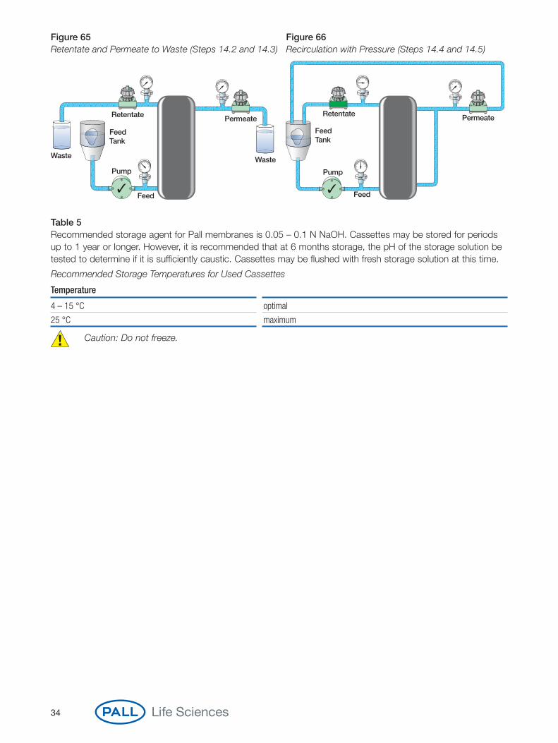
Figure 65 Figure 66Retentate and Permeate to Waste (Steps 14.2 and 14.3) Recirculation with Pressure (Steps 14.4 and 14.5)
Retentate
Feed Tank
Waste
Feed
Pump
Permeate
Waste
Retentate Permeate
Feed Tank
Feed
Pump
Table 5Recommended storage agent for Pall membranes is 0.05 – 0.1 N NaOH. Cassettes may be stored for periodsup to 1 year or longer. However, it is recommended that at 6 months storage, the pH of the storage solution betested to determine if it is sufficiently caustic. Cassettes may be flushed with fresh storage solution at this time.
Recommended Storage Temperatures for Used Cassettes
Temperature
4 – 15 °C optimal
25 °C maximum
Caution: Do not freeze.
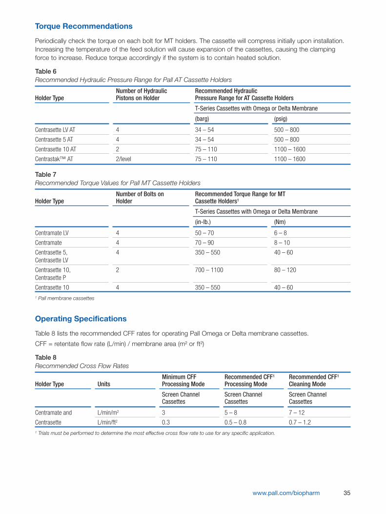
Torque Recommendations
Periodically check the torque on each bolt for MT holders. The cassette will compress initially upon installation.Increasing the temperature of the feed solution will cause expansion of the cassettes, causing the clampingforce to increase. Reduce torque accordingly if the system is to contain heated solution.
Table 6Recommended Hydraulic Pressure Range for Pall AT Cassette Holders
Number of Hydraulic Recommended Hydraulic Holder Type Pistons on Holder Pressure Range for AT Cassette Holders
T-Series Cassettes with Omega or Delta Membrane
(barg) (psig)
Centrasette LV AT 4 34 – 54 500 – 800
Centrasette 5 AT 4 34 – 54 500 – 800
Centrasette 10 AT 2 75 – 110 1100 – 1600
Centrastak™ AT 2/level 75 – 110 1100 – 1600
Table 7Recommended Torque Values for Pall MT Cassette Holders
Number of Bolts on Recommended Torque Range for MTHolder Type Holder Cassette Holders1
T-Series Cassettes with Omega or Delta Membrane
(in-lb.) (Nm)
Centramate LV 4 50 – 70 6 – 8
Centramate 4 70 – 90 8 – 10
Centrasette 5, 4 350 – 550 40 – 60Centrasette LV
Centrasette 10, 2 700 – 1100 80 – 120Centrasette P
Centrasette 10 4 350 – 550 40 – 601 Pall membrane cassettes
Operating Specifications
Table 8 lists the recommended CFF rates for operating Pall Omega or Delta membrane cassettes.
CFF = retentate flow rate (L/min) / membrane area (m² or ft²)
Table 8Recommended Cross Flow Rates
Minimum CFF Recommended CFF1 Recommended CFF1Holder Type Units Processing Mode Processing Mode Cleaning Mode
Screen Channel Screen Channel Screen Channel Cassettes Cassettes Cassettes
Centramate and L/min/m2 3 5 – 8 7 – 12
Centrasette L/min/ft2 0.3 0.5 – 0.8 0.7 – 1.21 Trials must be performed to determine the most effective cross flow rate to use for any specific application.
www.pall.com/biopharm 35
36
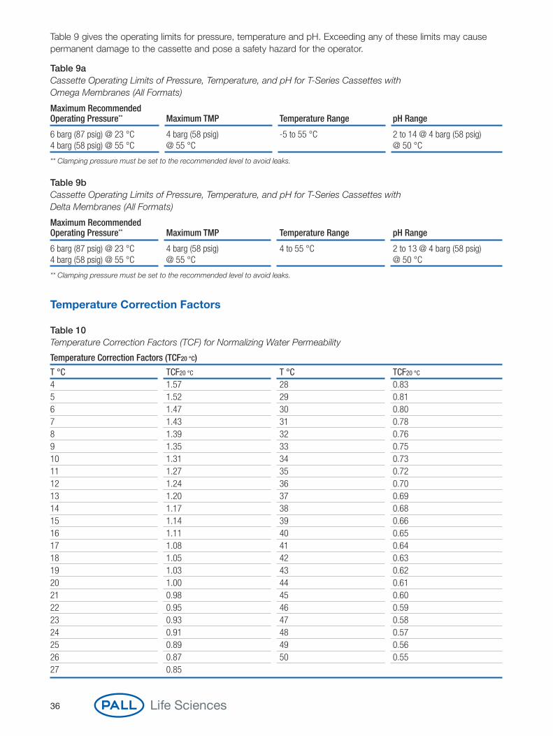
Table 9 gives the operating limits for pressure, temperature and pH. Exceeding any of these limits may causepermanent damage to the cassette and pose a safety hazard for the operator.
Table 9aCassette Operating Limits of Pressure, Temperature, and pH for T-Series Cassettes with Omega Membranes (All Formats)
Maximum RecommendedOperating Pressure** Maximum TMP Temperature Range pH Range
6 barg (87 psig) @ 23 °C 4 barg (58 psig) -5 to 55 °C 2 to 14 @ 4 barg (58 psig)4 barg (58 psig) @ 55 °C @ 55 °C @ 50 °C
** Clamping pressure must be set to the recommended level to avoid leaks.
Table 9bCassette Operating Limits of Pressure, Temperature, and pH for T-Series Cassettes with Delta Membranes (All Formats)
Maximum RecommendedOperating Pressure** Maximum TMP Temperature Range pH Range
6 barg (87 psig) @ 23 °C 4 barg (58 psig) 4 to 55 °C 2 to 13 @ 4 barg (58 psig)4 barg (58 psig) @ 55 °C @ 55 °C @ 50 °C
** Clamping pressure must be set to the recommended level to avoid leaks.
Temperature Correction Factors
Table 10Temperature Correction Factors (TCF) for Normalizing Water Permeability
Temperature Correction Factors (TCF20 °C)
T °C TCF20 °C T °C TCF20 °C
4 1.57 28 0.835 1.52 29 0.816 1.47 30 0.807 1.43 31 0.788 1.39 32 0.769 1.35 33 0.7510 1.31 34 0.7311 1.27 35 0.7212 1.24 36 0.7013 1.20 37 0.6914 1.17 38 0.6815 1.14 39 0.6616 1.11 40 0.6517 1.08 41 0.6418 1.05 42 0.6319 1.03 43 0.6220 1.00 44 0.6121 0.98 45 0.6022 0.95 46 0.5923 0.93 47 0.5824 0.91 48 0.5725 0.89 49 0.5626 0.87 50 0.5527 0.85
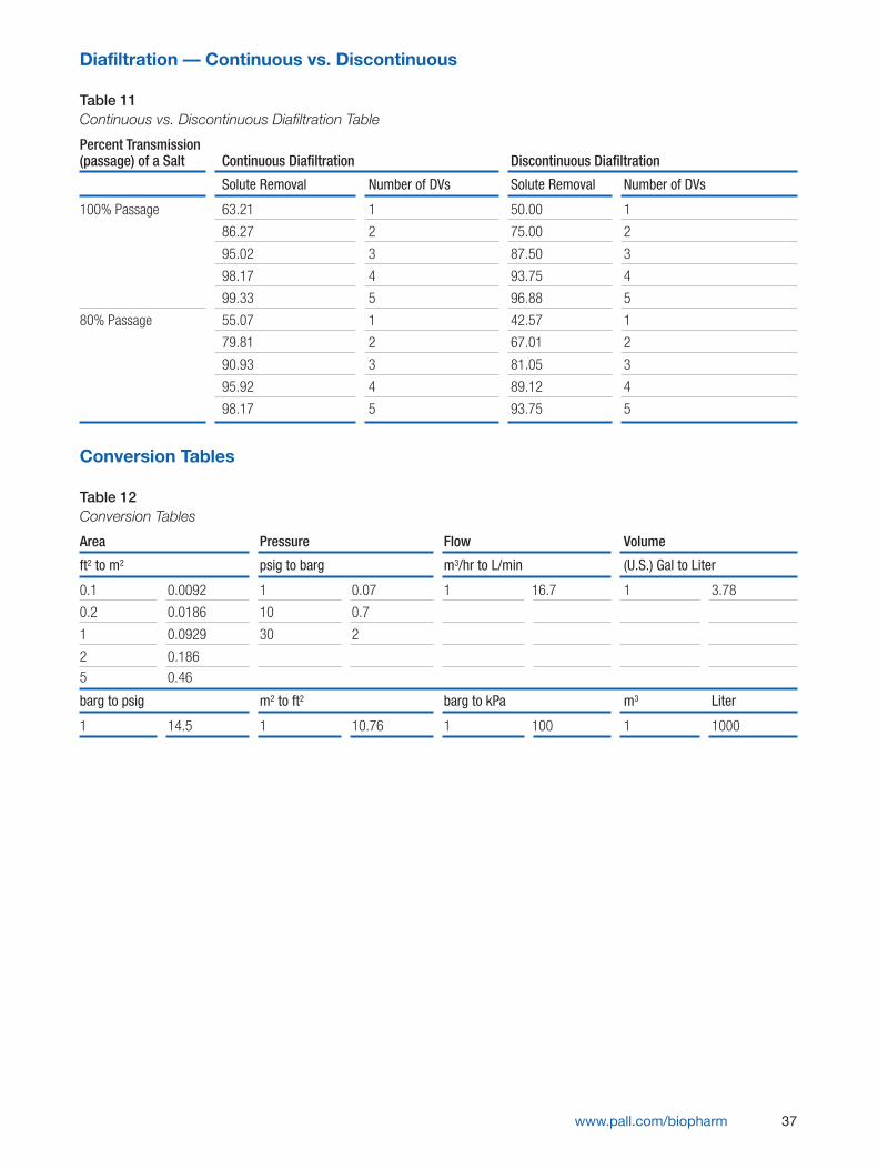
Diafiltration — Continuous vs. Discontinuous
Table 11Continuous vs. Discontinuous Diafiltration Table
Percent Transmission(passage) of a Salt Continuous Diafiltration Discontinuous Diafiltration
Solute Removal Number of DVs Solute Removal Number of DVs
100% Passage 63.21 1 50.00 1
86.27 2 75.00 2
95.02 3 87.50 3
98.17 4 93.75 4
99.33 5 96.88 5
80% Passage 55.07 1 42.57 1
79.81 2 67.01 2
90.93 3 81.05 3
95.92 4 89.12 4
98.17 5 93.75 5
Conversion Tables
Table 12Conversion Tables
Area Pressure Flow Volume
ft2 to m2 psig to barg m3/hr to L/min (U.S.) Gal to Liter
0.1 0.0092 1 0.07 1 16.7 1 3.78
0.2 0.0186 10 0.7
1 0.0929 30 2
2 0.186 5 0.46
barg to psig m2 to ft2 barg to kPa m3 Liter
1 14.5 1 10.76 1 100 1 1000
www.pall.com/biopharm 37
Europe+41 (0)26 350 53 00 phone+41 (0)26 350 53 53 [email protected] E-mail
United States800.717.7255 toll free (USA)516.484.5400 phone516.801.9548 [email protected] E-mail
International OfficesPall Corporation has offices and plants throughout the world in locations such as: Argentina, Australia, Austria,Belgium, Brazil, Canada, China, France, Germany, India, Indonesia, Ireland, Italy, Japan, Korea, Malaysia, Mexico,the Netherlands, New Zealand, Norway, Poland, Puerto Rico, Russia, Singapore, South Africa, Spain, Sweden,Switzerland, Taiwan, Thailand, the United Kingdom, the United States, and Venezuela. Distributors in all major industrial areas of the world.
The information provided in this literature was reviewed for accuracy at the time of publication. Product data may besubject to change without notice. For current information consult your local Pall distributor or contact Pall directly.
© 2009, Pall Corporation. Pall, , Centramate, Centrasette, Centrastak and Omega are trademarks ofPall Corporation. ® indicates a trademark registered in the USA and TM indicates a common law trademark.Filtration.Separation.Solution.SM is a service mark of Pall Corporation.
12/09, PDF, UK GN09.3100 USTR 2453b
Visit us on the Web at www.pall.com/biopharmE-mail us at [email protected]
Pall has the most comprehensive family of scalable separation products.


![CCNP BCMSN Quick Reference Sheets - Lagout Quick Reference... · CCNP BCMSN Quick Reference Sheets Exam 642-812 ... [ 4 ] CCNP BCMSN Quick Reference Sheets. ... switch would be used](https://static.fdocuments.us/doc/165x107/5a7a6ec87f8b9a05538dccf5/ccnp-bcmsn-quick-reference-sheets-lagout-quick-referenceccnp-bcmsn-quick-reference.jpg)

