
Quick reference guide IChill 290D/291D (F irmware rel. 1.8)
52
1592015850 Quick reference guide IC290D/291D FW 1.8 (rel 1.1) Page 1 of 52 Quick reference guide IChill 290D/291D (Firmware rel. 1.8)
Transcript of Quick reference guide IChill 290D/291D (F irmware rel. 1.8)

1592015850 Quick reference guide IC290D/291D FW 1.8 (rel 1.1)
Page 1 of 52
Quick reference guide
IChill 290D/291D(Firmware rel. 1.8)

1592015850 Quick reference guide IC290D/291D FW 1.8 (rel 1.1)
Page 2 of 52
Index1. General Advice ______________________22. General Features ____________________33. IC290D/291D Table of the
Features _____________________________44. User Interface________________________55. Table Of The Output Status In
Alarm Condition ____________________166. Wiring Connections_________________197. Electrical Connections______________218. Probe and relay configuration ______229. Table Of The Parameters____________2610. Technical Data ______________________52
1. General Advice
1.1 Please Read Before Using ThisManual This manual is part of the product and should be kept
near the instrument for easy and quick reference. The instrument shall not be used for purposes different
from those described hereunder. It cannot be used as a safety
device. Check the application limits before proceeding.
1.2 Safety Precautions Check the supply voltage is correct before connecting
the instrument. Do not expose to water or moisture: use the controller
only within the operating limits avoiding suddentemperature changes with high atmospheric humidity toprevent formation of condensation
Warning: disconnect all electrical connections beforeany kind ofmaintenance.
The instrument must not be opened. In case of failure or faulty operation send the instrument
back to thedistributor or to “Dixell s.r.l.” with a detailed description
of the fault. Consider the maximum current which can be applied to
each relay (seeTechnical Data). Ensure that the wires for probes, loads and the power
supply are separated and far enough from each other,without crossing or intertwining.
Fit the probe where it is not accessible by the end user. In case of applications in industrial environments, the
use of mainsfilters (our mod. FT1) in parallel with inductive loadscould be useful.
Full ManualDixell S.r.l. reserve to itself the right tomodify this instruction manual without anywarning.Last available can be downloaded from heinternet site. [email protected]

1592015850 Quick reference guide IC290D/291D FW 1.8 (rel 1.1)
Page 3 of 52
2. General Features
iCHILL IC290D/291D is an electronic controller for chiller unitapplications having one or two circuits: Air/air Air/water Water/water MotocondensingAdditional features : Heat pump with gas reversibility
2.1 Main FunctionChiller management: One circuit up to 4 compressors Two circuits with different compressor number per
circuit Double circuit up to 6 compressors Screw compressorsCompressor start up: Direct Part winding Star - deltaCompressor Soft start: With step valve Automatic start-unloading (without load). External by-pass gas valve.Capacity step control: Continuous control Step control Modulation control (screw compressors)Thermoregulation of the compressors Time running hours Number of start-up per hourCooling liquid injection With dedicated PTC probeHigh temperature alarm of the compressor dischargeside With dedicated PTC probeComplete management of two pump groups of the waterside 2 pumps evaporator side 2 pumps condenser sideOther display readings Safety digital inputs Compressors running hours Number of compressor start-up Pump running hours Delay counting to the next defrost Proportional output percentage status Compressors discharge temperatureAlarm reset with custom password Alarm list Compressor thermal protection alarmSingle circuit stand-by Circuit maintenance To work with only one circuitSingle compressor stand-by Compressor maintenance Compressor malfunctionPump down management
With dedicated pressure switch Low pressure switch Low pressure transducerUnloading circuit High temperature of the evaporator inlet water High temperature of the condenser inlet water (unit
with recovery) High condensing pressure Low evaporating pressureMaintenance messages Compressors Evaporator pumps Condenser pumpsAuxiliary relays Two configurable relay outputs not depending from the
control algorithm can be managed through NTC, PTCor pressure probes.
Weekly Energy saving Three different time bands per day (only with RTC
onboard) From digital inputWeekly ON/OFF: Three different time bands per day (only with RTC
onboard)Dynamic setpoint: Determined by analogue NTC input or 4÷20mA current
input.Change over : Automatic chiller or heat pump functioning depending
from NTC analogue input.Remote OFF: From configurable digital input.Remote change over: From configurable digital input.Hot start : Air / air unitDefrost management: Combined control with temperature and pressure Forced defrost with low temperature of external air From configurable digital input Manual from keyboardBoiler: For electrical integration heating or anti-freeze heatersTwo proportional outputs for condensing fan speedcontrol (inverter or phase cut) with configurable signal: PWM 0÷10Volt 4÷20mAFour proportional control outputs 0÷10V or ON/OFF To control the dumper in free cooling or recovery To control an external relayComplete alarm management Internal Data logger up to 100 eventsSupervisor / monitoring TTL output for XJ485 interface (Mod #Bus protocol) for
XWEB300 / XWEB3000 Dixell monitoring system forlocal and remote control

1592015850 Quick reference guide IC290D/291D FW 1.8 (rel 1.1)
Page 4 of 52
3. IC290D/291D Table of the Features
FEATURES IC290D IC291D
OUTPUT RELAYS
10
14
DIGITAL INPUTS
18 configurable configurable
PROBE INPUTS
10 configurable configurable
PROPORTIONAL OUTPUTS
2 PWM outputs for condensing fan
2 0÷10V or 4÷20mA for condensing fan configurable configurable
4 0÷10V configurable configurable
OTHER OUTPUTS
TTL
Output for remote keyboard VGI890
POWER SUPPLY
12 Vac/dc (+15%;-10%)
24 Vac/dc (± 10%) opt opt
OTHERS
Internal RTC opt opt
Buzzer opt opt
configurable = configurable through parameter opt = optional = default

1592015850 Quick reference guide IC290D/291D FW 1.8 (rel 1.1)
Page 5 of 52
4. User Interface
In the main visualization it is possible to read: status of the unit: cooling, heating, remote OFF or STD-BY date and time, available if the Ichill is provided by internal clock 4 probes value; it is possible to manage 4 lines to visualize the probe temperature / pressure
(parameters dP06..dP09) load / function status as showed below:
Compressor/s(blinking during the start up
delay)
Economy function
/ Water pump / Supply fan Unloading function
Condenser fan Economy or ON/OFF bytimetable
Electric heater Defrost
Sanitary water Alarm
Meaning of the keys:
Allows to read the value ofthe probes configured inthe Ichill
Allows to read/modify theset point
Allows to switch on theIchill in heating or coolingmode (see parameterCF78)
Allows to read the alarms
Allows to switch on theIchill in heating or coolingmode (see parameterCF78)
Allows to enter theSERVICE menù

1592015850 Quick reference guide IC290D/291D FW 1.8 (rel 1.1)
Page 6 of 52
Allows to put the Ichill inSTD-BY
Allows to read the maininformation of the circuits(compressor status, waterpump status, pressureprobe value,…)
Note:in case of alarm, press any key to silence the buzzer
4.1 Keyboard configuration
Keyboard configuration
It is possible to set:o contrast and backlight (it is strongly recommended to reduce as possible the
activation time of the backlight)o language selectiono read information about:
o Ichill firmware release (to verify the compatibility Ichill Visographkeyboard)
o Visograph keyboard firmware releaseo Visograph keyboard bin release
How to modify the configuration:
o press or to select the configuration to change
o press
o press or to change the configuration
o press to confirm

1592015850 Quick reference guide IC290D/291D FW 1.8 (rel 1.1)
Page 7 of 52
4.2 Chiller / Heat pump selection
If the Ichill is in STD-BY press o to switch on the machine.Meaning of the simbols:
CF78 = 0: pushing key the unit starts in chiller, pushing key the unit starts in heat pump
CF78 = 1: pushing key the unit starts in heat pump, pushing key the unit starts in chiller

1592015850 Quick reference guide IC290D/291D FW 1.8 (rel 1.1)
Page 8 of 52
When the Ichill is ON, press to put the machine in STD-BY.
4.3 Visualization / modification of the set point configuration
Visualization / modification of the set point
Press key to read the value of the set point (cooling set point if the Ichill is in cooling mode,heating set point if the Ichill is in heating mode, cooling and hating set point if the Ichill is in STD_BY orremote OFF, Sanitary water when enabled).It is also possible to read the status of the Energy saving, the status of the Dynamic set point and thereal value of the set point if the Energy saving or Dinamic set point are active.
To modify the set point (Cooling, Heating or Sanitary water): press or to select the value of the set point press press o to modify the value

1592015850 Quick reference guide IC290D/291D FW 1.8 (rel 1.1)
Page 9 of 52
press to confirm the operation
4.4 Alarm visualization and reset
Alarm visualization and reset
Press key to read the alarm status; the alarm status can be:
o Active: the alarm is still active and it is not possible to reset ito Reset: the alarm is not active and it is possible to reset it
Manual reset procedure:o press or to select the alarm;o press to reset the alarm
In case of compressor overload alarm when the password is requested, follow this step:o press o to select the compressor overload alarmo presso presso press or to insert the password value (parameter AL46)o press to confirm the operation

1592015850 Quick reference guide IC290D/291D FW 1.8 (rel 1.1)
Page 10 of 52
4.5 Menu SERVICE
Menu SERVICE
Pressing it is possible to read the following information:
Parameter programmingProgramming clockEnergy saving and ON/OFF schedulingCompressor maintenanceIt is possible to disable the compressor for maintenance, read theworking hours and number of start up (and reset them)
Water pump maintenanceIt is possible to read / reset the working hours
Circuit maintenance
Visualization and reset of the alarms
Visualization and reset of the alarm log
Defrost status
Electrical heater and pump down valve status
I/O statusScrew compressor informationIt is possible to read the discharge temperature, the liquid injection valvestatus and the minimum load valve status
Auxiliary output status
Upload and download parameter map with Hot KeySanitary water status, sanitary water temperature, antilegionellastatus, etc.Visograph configurationIt is possible to read the Ichill firmware version (for the compatibility withthe keyboard), the keyboard firmware release and keyboard bin release.It is possible to change the language, to set the contrast and thebacklight.

1592015850 Quick reference guide IC290D/291D FW 1.8 (rel 1.1)
Page 11 of 52
4.6 Parameters programming
Parameters programming
Pressing it is possible to read/modify the parameters value: select the level 1 (default) or level 2 or level (by pressing Pr2 or Pr3 key) press press or to enter the password press to confirm the display shows “Password OK!” (otherwise repeat the procedure) press to visualize the parameters

1592015850 Quick reference guide IC290D/291D FW 1.8 (rel 1.1)
Page 12 of 52
Pressing or it is possible to select the group of parameters to modify, thenpress .
How to modify the value of the parameter:
press or to select the parameter to modify press
press or to modify the value

1592015850 Quick reference guide IC290D/291D FW 1.8 (rel 1.1)
Page 13 of 52
press to confirm
Press or to scroll the parameters.
4.7 Clock programming and Energy saving / ON_OFF scheduling visualization
Clock programming and Energy saving / ON_OFF schedulingvisualization
It is possible to set the clock and read the Energy saving and the ON/OFF scheduler.How to set the clock:
o press or to select the date to modify (hour, minutes,date);
o press
o press or to modify the valueo press to confirm

1592015850 Quick reference guide IC290D/291D FW 1.8 (rel 1.1)
Page 14 of 52
Pressing or it is possible to read the information about the Energy savingand ON/OFF scheduling.To modify the hour of the time band and to enable the function is necessary to enter theparameter programming (ES parameters).
4.8 Parameters programming with Hot Key 64
Parameters programming with Hot Key 64
It is possible to use the HotKey 64 for: copy the parameter map from the HotKey 64 to the Ichill (Download) copy the parameter map from the Ichill to HotKey 64 (Upload)
Download from HotKey 64 to Ichill:this operation is enabled only if the Ichill is in STD-BY or remote OFF, otherwise the display shows themessage “Download enabled only in stand-by”.Download procedure: Insert the Hot Key 64 into the 5 ways connector through the hole at the top of the Ichill (see image
below) Select “Download from HotKey to device” Press ENTER if the operation was successful the display shows “OK”, otherwise shows “ERR”
Upload from Ichill to Hot Key 64:Upload procedure: Insert the Hot Key 64 into the 5 ways connector through the hole at the top of the Ichill (see image
below) Select “Upload from device to HotKey” Press ENTER if the operation was successful the display shows “OK”, otherwise shows “ERR”
In case of Upload / Download failure: Hot Key 64 not properly inserted in the 5 ways connector Hot Key model different to Hot Key 64

1592015850 Quick reference guide IC290D/291D FW 1.8 (rel 1.1)
Page 15 of 52
1592015850 Quick reference guide IC290D/291D FW 1.8 (rel 1.1)
Page 16 of 52
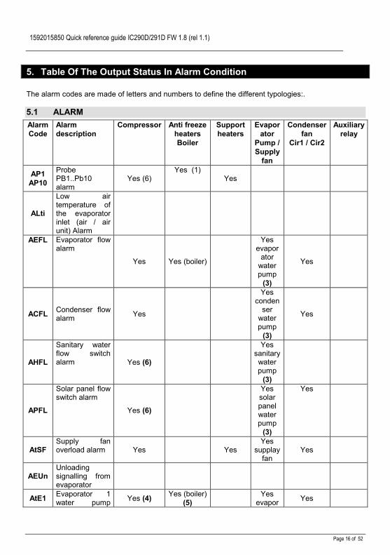
5. Table Of The Output Status In Alarm Condition
The alarm codes are made of letters and numbers to define the different typologies:.
5.1 ALARMAlarmCode
Alarmdescription
Compressor Anti freezeheatersBoiler
Supportheaters
Evaporator
Pump /Supply
fan
Condenserfan
Cir1 / Cir2
Auxiliaryrelay
AP1AP10
ProbePB1..Pb10alarm
Yes (6)Yes (1)
Yes
ALti
Low airtemperature ofthe evaporatorinlet (air / airunit) Alarm
AEFL Evaporator flowalarm
Yes Yes (boiler)
Yesevapor
atorwaterpump
(3)
Yes
ACFL Condenser flowalarm Yes
Yesconden
serwaterpump
(3)
Yes
AHFL
Sanitary waterflow switchalarm Yes (6)
Yessanitarywaterpump
(3)
APFL
Solar panel flowswitch alarm
Yes (6)
Yessolarpanelwaterpump
(3)
Yes
AtSFSupply fanoverload alarm Yes Yes
Yessupplay
fanYes
AEUnUnloadingsignalling fromevaporator
AtE1 Evaporator 1water pump Yes (4) Yes (boiler)
(5)Yes
evapor Yes

1592015850 Quick reference guide IC290D/291D FW 1.8 (rel 1.1)
Page 17 of 52
overload alarm atorwater
pump 1
AtE2Evaporator 2water pumpoverload alarm
Yes (4) Yes (boiler)(5)
Yesevapor
atorwater
pump 2
Yes
AtC1Condenser 1water pumpoverload alarm
Yes (4)
Yesconden
serwater
pump 1
Yes
AtC2Condenser 2water pumpoverload alarm
Yes (4)
Yesconden
serwater
pump 2
Yes
AEP1Evaporator 1water pumpmaintenance
AEP2Evaporator 2water pumpmaintenancesupport
ACP1Condenser 1water pumpmaintenance
ACP2Condenser 2water pumpmaintenance
ASAnSanitary waterpumpmaintenance
ASUnSolar panelwater pumpmaintenance
ArtC Clock alarm
Atr1Remotekeyboard n° 1alarm
Atr2Remotekeyboard n° 2alarm
ArtF Clock failureALOC Generic alarm Yes Yes Yes YesAEE Eeprom alarm Yes Yes Yes YesACF1ACF1
2
Configurationalarm Yes
Yes Yes Yes
ArtF Faulty clockArtC Clock error

1592015850 Quick reference guide IC290D/291D FW 1.8 (rel 1.1)
Page 18 of 52
AEUn
Unloadingsignalling fromhigh temp of.evaporatorwater
ALtiLow evaporatorinlettemperature inair/air unit
AEhtHigh watertemperatureinlat evaporator
Yes
(1) = if probe configured as anti-freeze / boiler control and Ar10 = 0(2) = if probe configured as auxiliary relay control(3) = manual alarm procedure(4) = compressors switched off when only 1 water pump is configured or both water pumps are in alarm(5) = Boiler heaters off with only 1 water pump configured or with 2 pumps but both in alarm from the corresponding digital inputs (in
this case the boiler heaters are on only with thermoregulation anti-freeze setpoint as evaporator protection function)(6) = If the faulty probe is the regulation probe or circuit probe (condenser probe, suction probe)
5.2 ALARM: circuit alarm
AlarmCode
Alarm description Compressorsof thecircuit(n)
Compressorsof the othercircuit
Fancondensingof the circuit(n)
Fancondensingof the other
circuit
b(n)HP High pressure switch of the circuit (n) Yes Yes after 60seconds
b(n)LP Low pressure switch of the circuit (n) Yes Yes
b(n)AC Anti-freeze in chiller of the circuit (n) Yes Yes
b(n)AH Anti-freeze in heat pump of the circuit (n) Yes Yes
b(n)hP High condensing pressure of the circuit (n) Yes Yes after 60seconds
b(n)hP High condensing temperature from NTC of thecircuit (n) Yes Yes after 60
seconds
b(n)LPLow condensing pressure - (evaporating with lowpressure transducer) with transducer of the circuitof the (n)
Yes Yes
b(n)lP Low condensing temperature NTC circuit (n) Yes Yes
b(n)tF Fan overload circuit (n) Yes Yes
b(n)PH Pump down alarm in stop regulation of the circuit(n) Yes Yes
b(n)PL Pump down in regulation start-up of the circuit (n) Yes Yes
b(n)dF Bad defrost circuit (n)
b(n)Cu Unloading from condenser high temp/press of thecircuit (n)
b(n)Cu Unloading from evaporator low temp/press of thecircuit (n) Yes Yes
b(n)rC Recovery function disabled in circuit (n)
b(n)ds Circuit (n) disabled from keyboard Yes Yes
b(n)Ac Anti-freeze circuit (n) message in chiller
b(n)Ah Anti-freeze circuit (n) message in heat pump

1592015850 Quick reference guide IC290D/291D FW 1.8 (rel 1.1)
Page 19 of 52
(n) identifies the circuit 1 or 2
5.3 ALARM: compressor alarm
Alarm Code Alarm description Compressor(n)
Compressors not involved
C(n)HP Compressor(n) high pressure switch Yes
C(n)oP Compressor(n) oil pressure switch / Oil levelswitch Yes
C(n)tr Compressor(n) overload Yes
C(n)dt Compressor high discharge temperature Yes
C(n)dS Compressor (n) disabled from keyboard Yes
C(n)Mn Compressor(n) maintenane
(n) identifies the compressor 1, 2 , 3 , 4 , 5 , 6
6. Wiring Connections
6.1 Hardware Resources: IC290D / 291D10 relays IC290D / 14relays IC291(MAX current on the relay contacts 5(2)A 250V; MAX current in the common line of the relays 12A250V)18 digital inputs (free voltage)10 analogue inputs: configurable ( 6 NTC or PTC, 4 NTC or pressure transducer 4÷20mA or ratio-metric 0÷ 5.0 Volt)2 PWM output (to manage the condenser fan)6 0..10V output1 output for remote keyboard (max 2 remote panels)1 TTL output to connect an “Hot Key 64” (parametrs programming)1 RS 485 output

1592015850 Quick reference guide IC290D/291D FW 1.8 (rel 1.1)
Page 20 of 52
6.2 Ichill 290/291D dimensions
All the measures are expressed in mm.
6.3 Keyboard VGI690 panel cut out

1592015850 Quick reference guide IC290D/291D FW 1.8 (rel 1.1)
Page 21 of 52
7. Electrical Connections
The instrument is provided with: 3 removable terminal blocks MOLEX with 0.5 mm2 wires: 16 / 8 /22 ways for digital / analogue
inputs and modulating outputs. 4 removable screw terminal block STELVIO for 2.5 mm2 wires connection: 3 / 4 / 5 / 6 ways for
the relay outputs. 5 ways connector for TTL RS485 interface outputs. 3 ways connector for keyboard VGI890 to be connected with the cable CABC3J15. The LW30 KIT is the complete kit with MOLEX + 3 mt wires already connected and the STELVIO
terminals. Check the connecitons and the line voltage before turning on the power supply. Keep low voltage cables, such as analogue/digital inputs/outputs and probes, away from power
cables and terminals.Respect the maximum load current of each relay output, in case of power loads use filtered contactors.

1592015850 Quick reference guide IC290D/291D FW 1.8 (rel 1.1)
Page 22 of 52
8. Probe and relay configuration
8.1 Analog input Pb1 - Pb2 - Pb7 -Pb8 - Pb9 - Pb10
Parameters involved:CF08 = Configuration PB1CF09 = Configuration PB2CF14 = Configuration PB7CF15 = Configuration PB8CF16 = Configuration PB9CF17 = Configuration PB100. Not enabled1. Temperature probe PTC for compressor
1 discharge2. Temperature probe PTC for compressor
2 discharge3. Temperature probe PTC for compressor
3 discharge4. Temperature probe PTC for compressor
4 discharge5. Temperature probe PTC for compressor
5 discharge6. Temperature probe PTC for compressor
6 discharge7. Temperature probe NTC for evaporator
inlet8. Temperature probe NTC for evaporator
1 outlet9. Temperature probe NTC for evaporator
2 outlet10. Temperature probe NTC for common
evaporator outlet11. Temperature probe NTC for common hot
water condenser / recovery inlet12. Temperature probe NTC for hot water of
the condenser / recovery circuit 1 inlet13. Temperature probe NTC for hot water of
the condenser / recovery circuit 2 inlet14. Temperature probe NTC for hot water of
the condenser / recovery circuit 1 outlet15. Temperature probe NTC for hot water of
the condenser / recovery circuit 2 outlet16. Temperature probe NTC for hot water of
the condenser / recovery common outlet17. Temperature probe NTC for free cooling
water inlet circuit18. Not Used
19. Temperature probe NTC for dynamicsetpoint external air / boiler / changeover
20. Temperature probe NTC for combineddefrost circuit 1
21. Temperature probe NTC for combineddefrost circuit 2
22. Temperature probe NTC for auxiliaryoutput 1
23. Temperature probe NTC for auxiliaryoutput 2
24. Temperature probe NTC sanitary water1
25. Temperature probe NTC sanitary water1
26. Temperature probe NTC solar panel27. Temperature probe NTC for condensing
circuit 128. Temperature probe NTC for condensing
circuit 2After the number 25 the display configurationcan be selected from o 1 to c67that allows toset an analogue input as digital input (seepolarity of the digital input/outputs).8.2 Analog input Configuration
Pb3 - Pb4 - Pb5 - Pb6Parameter involved:CF10 = Configuration PB3CF11 = Configuration PB4CF12 = Configuration PB5CF13 = Configuration PB60 Not enabled1 Temperature probe PTC for compressor
1 discharge2 Temperature probe PTC for compressor
2 discharge3 Temperature probe PTC for compressor
3 discharge4 Temperature probe PTC for compressor
4 discharge5 Temperature probe PTC for compressor
5 discharge6 Temperature probe PTC for compressor
6 discharge7 Temperature probe NTC for evaporator
inlet8 Temperature probe NTC for evaporator
outlet 19 Temperature probe NTC for evaporator
outlet 2

1592015850 Quick reference guide IC290D/291D FW 1.8 (rel 1.1)
Page 23 of 52
10 Temperature probe NTC for commonevaporator outlet
11 Temperature probe NTC for commonhot water condenser / recovery inlet
12 Temperature probe NTC for hot watercondenser / recovery inlet circuit 1
13 Temperature probe NTC for hot watercondenser / recovery inlet circuit 2
14 Temperature probe NTC for hot watercondenser / recovery outlet circuit 1
15 Temperature probe NTC for hot watercondenser / recovery outlet circuit 2
16 Temperature probe NTC for hot watercondenser / recovery common outletcircuit
17 Temperature probe NTC for free coolingwater inlet
18 Not Used19 Temperature probe NTC for external air
dynamic setpoint/ boiler / change over20 Temperature probe NTC for combined
defrost circuit 121 Temperature probe NTC for free cooling
water inlet 222 Temperature probe NTC for auxiliary
output 123 Temperature probe NTC for auxiliary
output 224 Temperature probe NTC sanitary water
125 Temperature probe NTC sanitary water
226 Temperature probe NTC solar panel27 Condenser probe circuit 1 ( temperature
NTC / pressure 4÷20 mA / ratio-metric0÷ 5Volt )
28 Condenser probe circuit 2 ( temperatureNTC / pressure 4÷20 mA / ratio-metric0÷ 5Volt )
29 Evaporator pressure probe circuit 1(pressure 4÷20 mA / ratio-metric 0÷5Volt )
30 Evaporator pressure probe circuit 1(pressure 4÷20 mA / ratio-metric 0÷5Volt )
31 Auxiliary output 1 pressure probecontrol (4÷20 mA / ratio-metric 0÷5Volt)
32 Auxiliary output 2 pressure probecontrol (4÷20 mA / ratio-metric 0÷5Volt)
33 Dynamic setpoint pressure probe (4÷20mA)
After the number 30 the display read-out goesfrom “o 1” to “c67 that allows to set ananalogue input as digital input (see polarityinput of digital inputs).8.3 Digital Input Configuration Id1
– Id18Parameters involved:CF36 = Configuration ID1…CF53 =Configuration ID180. Not enabled1. Remote ON / OFF2. Remote chiller / heat pump3. Flow switch/ Supply fan overload4. Flow switch of heated side5. Antifreeze heater circuit 16. Antifreeze heater circuit 27. High pressure switch circuit 18. High pressure switch circuit 29. Low pressure switch circuit 110. Low pressure switch circuit 211. Compressor 1 high pressure12. Compressor 2 high pressure13. Compressor 3 high pressure14. Compressor 4 high pressure15. Compressor 5 high pressure16. Compressor 6 high pressure17. Compressor 1 overload18. Compressor 2 overload19. Compressor 3 overload20. Compressor 4 overload21. Compressor 5 overload22. Compressor 6 overload23. Condenser fan overload of circuit 124. Condenser fan overload of circuit 225. Condenser fan overload of circuit 1 and
2 (comun)26. Water pump overload of evaporator 127. Water support pump overload of
evaporator28. Water pump overload of condenser 129. Water support pump overload of
condenser30. Not Used31. Not Used32. End defrost circuit 133. End defrost circuit 234. Energy Saving35. Pressure switch / compressor 1 oil36. Pressure switch / compressor 2 oil37. Pressure switch / compressor 3 oil

1592015850 Quick reference guide IC290D/291D FW 1.8 (rel 1.1)
Page 24 of 52
38. Pressure switch / compressor 4 oil39. Pressure switch / compressor 5 oil40. Pressure switch / compressor 6 oil41. Pump down pressure switch of circuit 142. Pump down pressure switch of circuit 243. Generic alarm from digital input with
stop regulation n° 144. Generic alarm from digital input with
stop or signal regulation n° 245. Operation working mode: by RTC or
keyboard46. Operation mode with supplay fan only47. Digital input of thermoregulation request
(condensing unit)48. Digital input of cooling request
(condensing unit)49. Digital input of heating request
(condensing unit)50. Request step 2 (condensing unit)51. Request step 3 (condensing unit)52. Request step 4 (condensing unit)53. Request step 5 (condensing unit)54. Request step 6 (condensing unit)55. Request step 7 (condensing unit)56. Request step 8 (condensing unit)57. Request step 9 (condensing unit)58. Request step 10 (condensing unit)59. Request step 11 (condensing unit)60. Request step 12 (condensing unit)61. Request step 13 (condensing unit)62. Request step 14 (condensing unit)63. Request step 15 (condensing unit)64. Request step 16 (condensing unit)65. Sanitary water flow switch66. Solar panel flow switch67. Only sanitary water8.4 Digital Output (relay)
Configuration RL1- RL14Parameter involved:CF54= Configuration RL1…CF67=Configuration RL140. Not enabled1. Alarm2. Evaporator water pump / Supply fan3. Support water pump of the evaporator4. Anti-freeze heater / integration heating /
boiler circuit 15. Anti-freeze heater / integration heating /
boiler circuit 26. Water pump of the condenser recovery
circuit
7. Support water pump of the condenserrecovery circuit
8. 4-way valve for chiller / heat pumpinversion of the circuit 1
9. 4-way valve for chiller / heat pumpinversion of the circuit 2
10. 1° condenser fan step ON/OFF controlof the circuit 1
11. 2° condenser fan step ON/OFF controlof the circuit 1
12. 3° condenser fan step ON/OFF controlof the circuit 1
13. 4° condenser fan step ON/OFF controlof the circuit 1
14. 1° condenser fan step ON/OFF controlof the circuit 2
15. 2° condenser fan step ON/OFF controlof the circuit 2
16. 3° condenser fan step ON/OFF controlof the circuit 2
17. 4° condenser fan step ON/OFF controlof the circuit 2
18. Solenoid valve of the pump-down circuit1
19. Solenoid valve of the pump-down circuit2
20. Recovery valve circuit 121. Recovery valve circuit 222. Free cooling ON/OFF valve23. Auxiliary output circuit 124. Auxiliary output circuit 225. Solenoid valve Intermittent for screw
compressor 126. Solenoid valve Intermittent for screw
compressor 227. Solenoid valve of the liquid injection for
compressor 128. Solenoid valve of the liquid injection for
compressor 229. Sanitary valve 130. Sanitary valve 231. Sanitary heater 132. Sanitary heater 233. Sanitary heater 334. Solar panel water pump35. Solar panel valve36. Sanitary water pump37. Hybrid exchanger 138. Hybrid exchanger 239. Direct start-up : compressor 1 relay
PW start: relay PW 1 of the compressor1

1592015850 Quick reference guide IC290D/291D FW 1.8 (rel 1.1)
Page 25 of 52
Star-delta start: relay line 1 of thecompressor 140. PW start: relay PW 2 of the compressor
1Star-delta start: relay linea 2 compressor1
41. Star centre of the Star-delta start of thecompressor 1
42. Capacity step valve 1 compressor 143. Capacity step valve 2 compressor 144. Capacity step valve 3 compressor 145. By-pass gas valve compressor 1start46. Direct start: compressor 2 start
PW start: relay 1 of the compressor 2Star-delta start: relay line 1 of the
compressor 247. PW start: relay PW 2 of the compressor
2Star-delta start: relay line 2 of the
compressor 248. Star centre of the Star-delta start of the
compressor 249. Capacity step valve 1 compressor 250. Capacity step valve 2 compressor 251. Capacity step valve 3 compressor 252. By-pass gas valve compressor 2 start53. Direct start: compressor 3 relay
PW start: relay PW 1 of the compressor3
Star-delta start: relay line 1 of thecompressor 354. PW start: relay PW 2 of the compressor
3Star-delta start: relay line 1 of the
compressor 355. Star centre of the Star-delta start of the
compressor 356. Capacity step valve 1 compressor 357. Capacity step valve 2 compressor 358. Capacity step valve 3 compressor 359. By-pass gas valve compressor 3 start60. Direct start: compressor 4 relay
PW start: PW 1 of the compressor 4Star-delta start: relay line 1 of the
compressor 461. PW start: relay PW 2 of the compressor
4Star-delta start: relay line 1 of the
compressor 462. Star centre of the Star-delta start of the
compressor 463. Capacity step valve 1 of the compressor
4
64. Capacity step valve 2 of the compressor4
65. Capacity step valve 3 of the compressor4
66. By-pass gas valve compressor 4 start67. Compressor 5 relay68. Compressor 6 relay8.5 Condenser proportional
control configuration (2outputs)
Proportional outputs used to configure aproportional output signal to condenser fancontrolParameters involved:CF68 = Condenser control configuration forcircuit 1CF69 = Condenser control configuration forcircuit 20= 0 ÷ 10Vdc (for external mono or three-phase fan control board)1= 4÷20mA (for external mono or three-phasefan control board)2= PWM (only for external mono-phase fancontrol board with cut phase control)8.6 Proportional output
configuration 0 ÷ 10 Vdc (4outputs)
Parameters involved:CF70 = Proportional output 1 configurationCF71 = Proportional output 2 configurationCF72 = Proportional output 3 configurationCF73 = Proportional output 4 configuration0 Not enabled1 not used2 not used3 not used4 Auxiliary output 0÷10V n° 15 Auxiliary output 0÷10V n° 26 Proportional output for modulatingcompressor 17 Proportional output for modulatingcompressor 2After the read-out number 4 the display goesfrom the label “o 1” to “c38 (see input/outputpolarity), that allow to configure the output asdigital output to control an external relay.

1592015850 Quick reference guide IC290D/291D FW 1.8 (rel 1.1)
Page 26 of 52
9. Table Of The Parameters
MENU SELECTIONLabel Description
ALL Shows all the parameters
ST Shows only the Thermoregulation parameters
CF Shows only the Configuration parameters
SD Shows only the Dynamic Setpoint parameters
ES Shows only the Energy Saving, RTC parameters
Cr Shows only the compressor rack parameters
CO Shows only the compressor parameters
US Shows only the Auxiliary Output parameters
FA Shows only the Fan Control parameters
Ar Shows only the Antifreeze Control parameters
DF Shows only the Defrost parameters
FS Shows only the Sanitary Water parameters
AL Shows only the Alarm parameters
ThermoregulationParameter Description min max u.m. ResolutionST 1 Chiller Setpoint ST02 ST03 °C/°F dec/intST 2 Chiller minimum Setpoint -30.0
-22 ST01 °C°F dec/int
ST 3 Chiller maximum Setpoint ST01 70.0158
°C°F dec/int
ST 4 Heat pump setpoint ST05 ST06 °C/°F dec/intST 5 Heat pump minimum Setpoint -30.0
-22 ST04 °C°F
Decint
ST 6 Heat pump maximum Setpoint ST04 70.0158
°C°F
Decint
ST 7 Regulation band in chiller mode 0.00
25.045
°C°F
Decint
ST 8 Regulation band in chiller heat pump 0.00
25.045
°C°F
Decint
ST 9 Thermoregulation probe selection in chiller0= Temperature probe NTC for evaporator inlet1= Temperature probe NTC for evaporator outlet 12= Temperature probe NTC for evaporator outlet 23= Temperature probe NTC for common evaporator outlet4= Temperature NTC probe from remote panel 15= Temperature NTC probe from remote panel 2
0 5

1592015850 Quick reference guide IC290D/291D FW 1.8 (rel 1.1)
Page 27 of 52
ST 10 Thermoregulation probe selection in heat pump0= Temperature probe NTC for evaporator inlet1= Temperature probe NTC for evaporator outlet 12= Temperature probe NTC for evaporator outlet 23= Temperature probe NTC for common evaporator outlet4= Temperature NTC probe from remote panel 15= Temperature NTC probe from remote panel 26= Temperature probe for water common inlet of the condenser7= Temperature probe for water inlet of the circuit # 1 condenser8= Temperature probe for water inlet of the circuit # 2 condenser9= Temperature probe for water outlet of the circuit # 1 condenser10= Temperature probe for water outlet of the circuit # 2condenser11= Temperature probe for water common otlet of the condenserATTENTIONTo have the same thermoregulation for chiller and heat pumpmode, set the parameters ST09 and ST10 with the same value
0 11
ST 11 Type of thermoregulation0= Proportional1= Neutral zone
0 1
Pr1 Password 0 999Pr2 Password 0 999Pr3 Password 0 999
Display read-outParameter Description min max M. u. ResolutiondP 1 Not useddP 2 Not useddP 3 Not useddP4 Not useddP5 Not used
Display read-out of the VGI890dP6 First probe displayed on Visograph 0 33dP7 Second probe displayed on Visograph 0 33dP8 Third probe displayed on Visograph 0 33dP9 Fourth probe displayed on Visograph 0 33
ConfigurationParameter Description min max M. u. Resolution
Unit ModelCF 1 Type of unit
0= Air / air Chiller1= Air / water Chiller2= Water / water Chiller
0 2
CF 2 Selection type rof unit1= only chiller2= only heat pump3= chiller and heat pump4= heat pump and free cooling5= chiller, heat pump and free cooling
1 5
CF 3 Condensing unit0= no1= si
0 1
CompressorsCF 4 Compressors number for circuit 1
1= 12= 23= 34= 4
0 4

1592015850 Quick reference guide IC290D/291D FW 1.8 (rel 1.1)
Page 28 of 52
CF 5 Compressors number for circuit 20= 01= 12= 23= 3
0 3
CF 6 Number of compressor parzialization0= none1= 12= 23= 3
0 3
Analog InputsCF 7 Pressure or temperature analogue input functioning
0 = Temperature / pressure NTC – 4÷20 mA :The condensing temperature is controlled with NTC probe whilefor the evaporating pressures of the circuits 1 and 2 and thepressure probe configured as auxiliary output 1 and 2 arecontrolled with 4÷20mA transducers.1 = Pressure control with 4÷20 mA:To control the evaporating and condensing pressures it isnecessary a 4÷20mA transducer.2 = Temperature / pressure NTC – 0÷5Vdc:The condensing temperature is controlled with NTC probe whilefor the evaporating pressures of the circuits 1 and 2 and thepressure probe configured as auxiliary output 1 and 2 arecontrolled with 0÷5Vdc transducers.3 = Pressure control with 0÷5Vdc:To control the evaporating and condensing pressures it isnecessary a ratiometric 0÷5Vdc transducer.
0 3
CF 8 PB1 ConfigurationIf configured as digital input
0o 1
28c67
CF 9 PB2 ConfigurationIf configured as digital input
0o 1
28c67
CF 10 PB3 ConfigurationIf configured as digital input
0o 1
33c67
CF 11 PB4 ConfigurationIf configured as digital input
0o 1
33c67
CF 12 PB5 ConfigurationIf configured as digital input
0o 1
33c67
CF 13 PB6 ConfigurationIf configured as digital input
0o 1
33c67
CF 14 PB7 ConfigurationIf configured as digital input
0o 1
28c67
CF 15 PB8 ConfigurationIf configured as digital input
0o 1
28c67
CF 16 PB9 ConfigurationIf configured as digital input
0o 1
28c67
CF 17 PB10 ConfigurationIf configured as digital input
0o 1
28c67
Probe OffsetCF 18 PB1 Offset -12.0
-2112.021
°C°F
Decint
CF 19 PB2 Offset -12.0-21
12.021
°C°F
Decint
CF 20 PB3 Offset -12.0-21-5.0-72
12.0215.072
°C°Fbarpsi
Decintdecint

1592015850 Quick reference guide IC290D/291D FW 1.8 (rel 1.1)
Page 29 of 52
CF 21 PB4 Offset -12.0-21-5.0-72
12.0215.072
°C°Fbarpsi
Decintdecint
CF 22 PB5 Offset -12.0-21-5.0-72
12.0215.072
°C°Fbarpsi
Decintdecint
CF 23 PB6 Offset -12.0-21-5.0-72
12.0215.072
°C°Fbarpsi
Decintdecint
CF 24 PB7 Offset -12.0-21
12.021
°C°F
Decint
CF 25 PB8 Offset -12.0-21
12.021
°C°F
Decint
CF 26 PB9 Offset -12.0-21
12.021
°C°F
Decint
CF 27 PB10 Offset -12.0-21
12.021
°C°F
Decint
CF 28 Pressure value at 4mA or 0.5 Vdc of the PB3 transducer 00
50.0725
Barpsi
Decint
CF 29 Pressure value at 20mA or 5 Vdc of the PB3 transducer 00
50.0725
Barpsi
Decint
CF 30 Pressure value at 4mA or 0.5 Vdc of the PB4 transducer 00
50.0725
Barpsi
Decint
CF 31 Pressure value at 20mA or 5 Vdc of the PB4 transducer 00
50.0725
Barpsi
Decint
CF 32 Pressure value at 4mA or 0.5 Vdc of the PB5 transducer 00
50.0725
Barpsi
Decint
CF 33 Pressure value at 20mA or 5 Vdc of the PB5 transducer 00
50.0725
Barpsi
Decint
CF 34 Pressure value at 4mA or 0.5 Vdc of the PB6 transducer 00
50.0725
Barpsi
Decint
CF 35 Pressure value at 20mA or 5 Vdc of the PB6 transducer 00
50.0725
Barpsi
Decint
Digital InputsCF 36 Configuration of ID1 0 c67CF 37 Configuration of ID2 0 c67CF 38 Configuration of ID3 0 c67CF 39 Configuration of ID4 0 c67CF 40 Configuration of ID5 0 c67CF 41 Configuration of ID6 0 c67CF 42 Configuration of ID7 0 c67CF 43 Configuration of ID8 0 c67CF 44 Configuration of ID9 0 c67CF 45 Configuration of ID10 0 c67CF 46 Configuration of ID11 0 c67CF 47 Configuration of ID12 0 c67CF 48 Configuration of ID13 0 c67CF 49 Configuration of ID14 0 c67CF 50 Configuration of ID15 0 c67CF 51 Configuration of ID16 0 c67CF 52 Configuration of ID17 0 c67CF 53 Configuration of ID18 0 c67
Relay OutputsCF 54 Configuration of RL1 0 -o1 c68

1592015850 Quick reference guide IC290D/291D FW 1.8 (rel 1.1)
Page 30 of 52
CF 55 Configuration of RL2 0 -o1 c68CF 56 Configuration of RL3 0 -o1 c68CF 57 Configuration of RL4 0 -o1 c68CF 58 Configuration of RL5 0 -o1 c68CF 59 Configuration of RL6 0 -o1 c68CF 60 Configuration of RL7 0 -o1 c68CF 61 Configuration of RL8 0 -o1 c68CF 62 Configuration of RL9 0 -o1 c68CF 63 Configuration of RL10 0 -o1 c68CF 64 Configuration of RL11 0 -o1 c68CF 65 Configuration of RL12 0 -o1 c68CF 66 Configuration of RL13 0 -o1 c68CF 67 Configuration of RL14 0 -o1 c68
Condensing proportional outputsCF 68 Circuit 1 output signal:
0= 0 – 10Vdc1= 4 ÷ 20mA2= PWM for mono phase fan control board
0 2
CF 69 Circuit 2 output signal:0= 0 – 10V1= 4 ÷ 20Ma2= PWM for mono phase fan control board
0 2
Proportional outputCF 70 Proportional output “out 3”
0= Not enabled1= Not used2= Not used3= Not used4= Auxiliary output 0÷10V n° 15= Auxiliary output 0÷10V n° 26= Proportional output for inverter circuit 1 compressor n° 27= Proportional output for inverter circuit 2 compressor n° 2Relay driver ON / OFF
0
o 1
7
C38
CF 71 Proportional output “out 4”0= Not enabled1= Not used2= Not used3= Not used4= Auxiliary output 0÷10V n° 15= Auxiliary output 0÷10V n° 26= Proportional output for inverter circuit 1 compressor n° 27= Proportional output for inverter circuit 2 compressor n° 2Relay driver ON / OFF
0
o 1
7
C38
CF 72 Proportional output “out 5”0= Not enabled1= Not used2= Not used3= Not used4= Auxiliary output 0÷10V n° 15= Auxiliary output 0÷10V n° 26= Proportional output for inverter circuit 1 compressor n° 27= Proportional output for inverter circuit 2 compressor n° 2Relay driver ON / OFF
0
o 1
7
C38

1592015850 Quick reference guide IC290D/291D FW 1.8 (rel 1.1)
Page 31 of 52
CF 73 Proportional output “out 6”0= Not enabled1= Not used2= Not used3= Not used4= Auxiliary output 0÷10V n° 15= Auxiliary output 0÷10V n° 26= Proportional output for inverter circuit 1 compressor n° 27= Proportional output for inverter circuit 2 compressor n° 2Relay driver ON / OFF
0
o 1
7
C38
Remote keyboardCF 74 Remote keyboard 1 configuration
0= Not enabled1= Enabled model with ambient temperature sensor2= Enabled model without ambient temperature sensor
0 2
CF 75 Remote Panel 2 configuration0= Not enabled1= Enabled model with ambient temperature sensor2= Enabled model without ambient temperature sensor
0 2
CF 76 Offset of the probe of the remote terminal 1 -12.0-21
12.021
°C°F
Decint
CF 77 Offset of the probe of the remote terminal 2 -12.0-21
12.021
°C°F
Decint
Icon functionCF 78 Icon function
0= chiller / heat pump1= chiller / heat pump
0 1
Chiller / heat pump selection modeCF 79 0= Chiller / Heat pump selection by keyboard
1= Chiller / Heat pump selection by digital input2= Chiller / Heat pump selection by analogue input
0 2
Automatic Change overCF 80 Automatic change over setpoint for chiller/ heat pump selection
(CF79 = 2)-30.0-22
70.0158
°C°F
Decint
CF 81 Automatic change over differential (CF79 = 2) 00
25.045
°C°F
Decint
Unit of measurementCF 82 °C or °F selection
0= °C / °BAR1= °F / °psi
0 1
Supply voltage frequencyCF 83 Power supply frequency
0= 50 Hz1= 60 Hz2= cc voltage(ATTENTIONWhen CF83 = 2 the proportional outputs for fan control are notenabled and the frequency alarm is inhibited)
0 2
Serial AddressCF 84 Serial address 1 247CF 85 Firmware ReleaseCF 86 Eeprom parameter map
Regulation of unbalanced compressors (different power)CF 87 Compressor 1 capacity 0 100%CF 88 Compressor 2 capacity 0 100%CF 89 Compressor 3 capacity 0 100%

1592015850 Quick reference guide IC290D/291D FW 1.8 (rel 1.1)
Page 32 of 52
CF 90 Compressor 4 capacity 0 100%CF 91 Compressor 5 capacity 0 100%CF 92 Compressor 6 capacity 0 100%CF 93 Maximum number of start up of the compressor in 15 minutes
0= Not enabled 0 15
Working mode of the compressorCF 94 Working mode of the compressor
0 = chiller and heat pump1 = only chiller2 = only heat pump
0 2
Hybrid exchangersCF 95 Enable hybrid exchangers 0 1
Dynamic SetpointParameters Description min max M. u. ResolutionSd 1 Maximum dynamic Offset in chiller mode -30.0
-5430.054
°C°F
Decint
Sd 2 Maximum dynamic Offset in heat pump mode -30.0-54
30.054
°C°F
Decint
Sd 3 External air setpoint in chiller mode -30.0-22
70.0158
°C°F
Decint
Sd 4 External air setpoint in heat pump mode -30-22
70.0158
°C°F
Decint
Sd 5 External air differential in chiller mode -30.0-54
30.054
°C°F
Decint
Sd 6 External air differential in heat pump mode -30.0-54
30.054
°C°F
Decint
Sd 7Dynamic set point: summer offset analog 1
-30.0-54
30.054
°C°F
Decint
Sd 8Dynamic set point: winter offset analog 1
-30.0-54
30.054
°C°F
Decint
Sd 9Summer outside temperature analog 1
-30-22
70.0158
°C°F
Decint
Sd 10Winter outside temperature analog 1
-30-22
70.0158
°C°F
Decint
Sd 11Summer outside temp. differential analog 1
-30.0-54
30.054
°C°F
Decint
Sd 12Winter outside temp. differential analog 1
-30.0-54
30.054
°C°F
Decint
Sd 13Dynamic set point: summer offset analog 2
-30.0-54
30.054
°C°F
Decint
Sd 14Dynamic set point: winter offset analog 2
-30.0-54
30.054
°C°F
Decint
Sd 15Summer outside temperature analog 2
-30-22
70.0158
°C°F
Decint
Sd 16Winter outside temperature analog 2
-30-22
70.0158
°C°F
Decint
Sd 17Summer outside temp. differential analog 2
-30.0-54
30.054
°C°F
Decint
Sd 18Winter outside temp. differential analog 2
-30.0-54
30.054
°C°F
Decint
Sd 19Dynamic set point: summer offset relay AUX1
-30.0-54
30.054
°C°F
Decint
Sd 20Dynamic set point: winter offset relay AUX1
-30.0-54
30.054
°C°F
Decint
Sd 21Summer outside temperature relay AUX1
-30-22
70.0158
°C°F
Decint

1592015850 Quick reference guide IC290D/291D FW 1.8 (rel 1.1)
Page 33 of 52
Sd 22Winter outside temperature relay AUX1
-30-22
70.0158
°C°F
Decint
Sd 23Summer temperature differential relay AUX1
-30.0-54
30.054
°C°F
Decint
Sd 24Winter temperature differential relay AUX1
-30.0-54
30.054
°C°F
Decint
Sd 25Dynamic set point: summer offset relay AUX2
-30.0-54
30.054
°C°F
Decint
Sd 26Dynamic set point: winter offset relay AUX2
-30.0-54
30.054
°C°F
Decint
Sd 27Summer outside temperature relay AUX2
-30-22
70.0158
°C°F
Decint
Sd 28Winter outside temperature relay AUX2
-30-22
70.0158
°C°F
Decint
Sd 29Summer temperature differential relay AUX2
-30.0-54
30.054
°C°F
Decint
Sd 30Winter temperature differential relay AUX2
-30.0-54
30.054
°C°F
Decint
Energy savingParameters Description min max udm RisoluzioneES 1 Start of the Time band 1 (0÷24) 0 24.00 Hr 10 MinES 2 End of the Time Band 1 (0÷24) 0 24.00 Hr 10 MinES 3 Start of the Time band 2 (0÷24) 0 24.00 Hr 10 MinES 4 End of the Time Band 2 (0÷24) 0 24.00 Hr 10 MinES 5 Start of the Time band 3 (0÷24) 0 24.00 Hr 10 MinES 6 End of the Time Band 3 (0÷24) 0 24.00 Hr 10 MinES 7 Monday: energy saving activated
Automatic unit on-off 0 - 0 7 - 7
ES 8 Tuesday energy saving activatedAutomatic unit on-off 0 - 0 7 - 7
ES 9 Wednesday energy saving activatedAutomatic unit on-off 0 - 0 7 - 7
ES 10 Thursday energy saving activatedAutomatic unit on-off 0 - 0 7 - 7
ES 11 Friday energy saving activatedAutomatic unit on-off 0 - 0 7 - 7
ES 12 Saturday energy saving activatedAutomatic unit on-off 0 - 0 7 - 7
ES 13 Sunday energy saving activatedAutomatic unit on-off 0 - 0 7 - 7
ES 14 Energy Saving setpoint offset in chiller mode -30.0-54
30.054
°C°F
Decint
ES 15 Energy Saving differential in chiller mode 0.00
25.045
°C°F
Decint
ES 16 Energy Saving setpoint offset in heat pump mode -30.0-54
30.054
°C°F
Decint
ES 17 Energy Saving differential in heat pump mode 0.00
25.045
°C°F
Decint
ES 18 Maximum ON time when the unit is switched on by keyboardstarting from OFF state by RTC0= Not enabled
1 250 Min 10 Min
Compressors rackCr1 Type of functioning compressor rack
0= Not enabled1= regulation by ST09 probe2 = regolation by pressure probe (Evaporator pressure probe)
0 2

1592015850 Quick reference guide IC290D/291D FW 1.8 (rel 1.1)
Page 34 of 52
Cr2 Set point compressor suction probe Cr03 Cr04 BarPsi
Decint
Cr3 Minimum set point compressor suction probe 0 Cr03 BarPsi
Decint
Cr4 Maximum set point compressor suction probe Cr03 50725
BarPsi
Decint
Cr5 Regulation band suction probe 0.11
14.0203
BarPsi
Decint
Cr6 Set energy saving compressor rack 0.00
50.0725
Barpsi
Decint
Cr7 Differential energy savingcompressor rack 0.11
14.0203
BarPsi
Decint
Cr8 Number of compressors enabled in case of failure probe0 ÷ 6 0 6
Cr9 Number od ventilation step in case of failure probe0 ÷ 4 0 4
CompressorsParameters Description min max udm RisoluzioneCO 1 Minimum compressor ON time after the start-up. 0 250 10
sec 10 sec
CO 2 Minimum compressor OFF time after the switching off. 0 250 10sec 10 sec
CO 3 ON delay time between two compressors or compressor andvalve. During this time the led of the next resource is blinking. 1 250 Sec
CO 4 OFF delay time between two compressors or compressor andvalve. During this time the led of the next resource is blinking. 0 250 Sec
CO 5 Output time delay after the main power supply start-up to the unit.All the loads are delayed in case of frequently power failures. 0 250 10
Sec 10 sec
Capacity ControlCO 6 Functioning (see Capacity Control)
0= With on/off steps1= Continuous with steps and direct action2= Continuous with steps and reverse action3= Continuous with steps and direct total action
0 3
CO 7 Start-up with minimum compressor power / automatic start-unloading valve0 = Only at the compressor start-up (Minimum power automaticstart-unloading valve off)1= At the compressor start-up and during the termoregulation(Minimum power / automatic start-unloading valve off)2 = Only at the screw compressor start-up (Minimum powerautomatic start-unloading valve off)3= At the compressor start-up and during the termoregulation(Minimum power / Unloading valve ON with compressor off)
0 3
CO 8 Relay ON time of the Solenoid valve Intermittent for screwcompressor, with 0 the function is not enabled. 0 250 Sec
CO 9 Relay OFF time of the Solenoid valve Intermittent for screwcompressor 0 250 Sec
Compressor start-upCO 10 Kind of compressor start-up
0= Direct ( vedi avviamento compressors )1= Part - winding2= Star-delta
0 2

1592015850 Quick reference guide IC290D/291D FW 1.8 (rel 1.1)
Page 35 of 52
CO 11 If CO10= 1 part - winding start-up time. To change the time delaybetween the two contactors of the two compressor circuits.Se CO10= 2 Star-delta start-up time. To change the time delaybetween the contactor of the line 1 and the contactor of the centreof the star. (see part – winding /start-triangle functioning)
0 100Dec.
diSec
0.1 sec
CO 12 If CO10= 2 Time of Star-delta start. Time delay to turn off thecentre star contactor and to turn on the line 2 contactor (see Star-delta functioning)
0 50Dec.
diSec
0.1 sec
CO 13 By-pass gas valve start-up time / automatic start-unloading valve(capacity step control) 0 250 sec
Rotating – Balancing – Compressors ThermoregulationCO 14 Compressor rotation (See compressor rotation)
0 = Sequential1 = Compressors rotation based on time running hours2 = Compressors rotation based on number of starts-up
0 2
CO 15 Circuit balancing (See Circuit balancing)0= Circuit saturation1= Circuit balancing
0 1
Evaporator water pumpCO 16 Operative mode of the evaporator pump / supply fan (See
Evaporator pump function)0= Not enabled (evaporator pump or supply fan).1= Continuous. When the unit is running in Chiller or HP thepump or the supply fan is running.2= With compressor. When a compressor is running also thepump or the supply fan is running.
0 2
CO 17 ON compressor delay after water pump / supply fan start-up (Seewater pump functioning). 1 250 Min
CO 18 OFF delay evaporator water pump / supply fan after compressorswitching OFF. This delay is also active when the unit is turned instand-by (See evaporator water pump function).
0 250 Min
CO 19 Number of time running hours for pump rotation (See water pumpgroup function) 0 999 10Hr 10Hr
CO 20 Time to make run the pumps together before rotating from one tothe other (See water pump group function) 0 250 Sec
Condenser water pumpCO 21 Operative mode for condenser water pump (See condenser water
pump function)0= Not enabled.1= Continuous. When the unit is running in Chiller or HP the isrunning.2= With compressor. When a compressor is running also thepump is running.
0 2
CO 22 FreeCO 23 OFF delay condenser water pump after compressor switching
OFF. This delay is also active when the unit is turned in stand-by(See evaporator water pump function).
0 250 Min
CO 24 Number of time running hours for pump rotation (See water pumpgroup function). 0 999 10Hr 10Hr
CO 25 Time to make run the pumps together before rotating from one tothe other (See water pump group function). 0 250 Sec
Load maintenanceCO 26 Compressor 1 hour counter set 0 999 10 Hr 10 HrCO 27 Compressor 2 hour counter set 0 999 10 Hr 10 HrCO 28 Compressor 3 hour counter set 0 999 10 Hr 10 HrCO 29 Compressor 4 hour counter set 0 999 10 Hr 10 HrCO 30 Compressor 5 hour counter set 0 999 10 Hr 10 HrCO 31 Compressor 6 hour counter set 0 999 10 Hr 10 Hr

1592015850 Quick reference guide IC290D/291D FW 1.8 (rel 1.1)
Page 36 of 52
CO 32 “Evaporator pump / Supply fan” hour counter set 0 999 10 Hr 10 HrCO 33 2nd Evaporator pump hour counter set 0 999 10 Hr 10 HrCO 34 Condenser pump hour counter set 0 999 10 Hr 10 HrCO 35 2nd Condenser pump hour counter set 0 999 10 Hr 10 Hr
Pump downCO 36 Pump down operating mode (See pump down ON/OFF function)
0= Not enabled1= Unit off with pump–down, unit on without pump–down2= Unit off with pump–down, unit on with pump–down3= Chiller mode off with pump–down, chiller mode on withoutpump–down4= Chiller mode off with pump–down, chiller mode on with pump–down
0 4
CO 37 Pump–down pressure setpoint (See pump down ON/OFFfunction)
00
50.0725
Barpsi
Decint
CO 38 Pump-down pressure differential (See pump down ON/OFFfunction)
00
14.0203
Barpsi
Decint
CO 39 Maximum pump–down time duration at start-up and stop (Seepump down ON/OFF function) 0 250 Sec
Evaporator UnloadingCO 40 Unloading compressor setpoint in chiller. From high temperature
of the evaporator water inlet (See unloading function).-300
70.0725
°C°F
Decint
CO 41 Unloading Differential. From high temperature of the evaporatorwater inlet (See unloading function).
0.00
25.045
°C°F
Decint
CO 42 Delay time to engage the Unloading function from hightemperature of the evaporator water inlet (See unloadingfunction).
1 250 10Sec 10sec
CO 43 Maximum unloading duration time to keep activated theUnloading function from high temperature of the evaporator waterinlet (See unloading function).
0 250 Min
Condenser UnloadingCO 44 Unloading compressor setpoint. From temperature / pressure in
chiller mode (See unloading function).00
50.0725
Barpsi
Decint
CO 45 Unloading Differential. From temperature / pressure in chillermode (See unloading function).
0.00
14.0203
BarPsi
Decint
CO 46 Unloading compressor setpoint. From temperature / pressure inHP mode (See unloading function).
00
50.0725
Barpsi
Decint
CO 47 Unloading Differential. From temperature / pressure in HP mode(See unloading function).
0.00
14.0203
BarPsi
Decint
CO 48 Maximum unloading duration time from temperature/pressurecontrol. 1 250 Min
CO 49 Number of steps for circuit with active unloading1= 1st step2= 2nd step3= 3rd step
1 3
CO 50 Minimum ON time of the capacity step after the unloadingfunction start (only for capacity compressor) 0 250 Sec
Compressor liquid injectionCO 51 Setpoint of the solenoid valve (on) of the liquid injection 0
0150302
°C°F
Dec / intint
CO 52 Setpoint of the solenoid valve (off) of the liquid injection 0.00
25.045
°C°F
Decint
Management resource in neutral zoneCO 53 Maximum time of work in neutral zone without insert resource 0 250 Min 10 MinCO 54 Maximum time of work in neutral zone without rotation resource 0 999 Hr 1Hr
Evaporator low water temperature Unloading

1592015850 Quick reference guide IC290D/291D FW 1.8 (rel 1.1)
Page 37 of 52
CO 55 Set point unloading compressor from low evaporator watertemperature -30.0
-2270.0158
°C°F
Decint
CO 56 Differential unloading compressor from low evaporator watertemperature 0.1
025.045
°C°F
Decint
CO 57 Maximum unloading duration time from low evaporator watertemperature 0 250 Min
Pump down to timeCO 58 maximum time pump-down in stopped
CO58 = 0 Not enabled 0 250 Sec
CO 59 maximum time pump-down in startedCO59 = 0 Not enabled 0 250 Sec
Compressor inverter controlledCO 60 Maximum time start up compressor inverter controlled 0 250 sec
CO 61 Minimum value proportional output from start up compressor 0 100 %
CO 62 Minimum time capacity variation from start up compressorinverter controlled 0 250 sec
CO 63 Minimum percentage continuative of work of the compressorinverter controlled before to start counting CO64 time 0 100 %
CO 64 Maximum time continuative of work of the compressor withpercentage less of CO63 0 250 Min 10 Min
CO 65 Time of forcing the compressor inverter controlled to themaximum power 0 250 sec 10sec
CO 66 Maximum time continuative of work of the compressor invertercontrolled 0 999 Hr 1Hr
CO 67 Minimum value of the compressor 1 inverter controlled 0 CO68 %
CO 68 Maximum value of the compressor 1 inverter controlled CO67 100 %CO 69 Minimum value of the compressor 2 inverter controlled 0 CO70 %CO 70 Maximum value of the compressor 2 inverter controlled CO69 100 %CO 71 Minimum time capacity variation compressor inverter controlled 1 250 sec
Tamdem functionCO 72 Maximum operating time of a single compressor 0 250 Min
Load maintenanceCO 73 Sanitary water pump hour counter 0 999 10 Hr 10 HrCO 74 Solar panel water pump hour counter 0 999 10 Hr 10 Hr
4 way valveCO 75 Forced time to reverse the 4 way valve when the compressor is
switched off0 250 sec
Auxiliary relay menu functionParameters Description min max M. U. Resolution
Auxiliary relay of the circuit 1

1592015850 Quick reference guide IC290D/291D FW 1.8 (rel 1.1)
Page 38 of 52
US 1 Auxiliary relay 1 operating mode (See graph and auxiliary relayfunctions)0= Not enabled1= Always available with direct action2= Available only when the unit is on with direct action3= Always available with reverse action4= Available only when the unit is on with reverse action
0 4
US 2 Analog input configuration for auxiliary relay 1 control. Allows to selectwhich probe value Pb1..Pb10 controls the relay 1 10
US 3
Auxiliary relay 1 summer minimum set point
-30.0-220.00
US5
°C°FBarPsi
Decint
Decint
US 4
Auxiliary relay 1 summer maximum set point
US5
70.015850.0725
°C°FBarPsi
Decint
Decint
US 5
Auxiliary relay 1 summer set point
US3 US4
°C°FBarPsi
Decint
Decint
US 6
Auxiliary relay 1 winter minimum set point
-30.0-220.00
US8
°C°FBarPsi
Decint
Decint
US 7
Auxiliary relay 1 winter maximum set point
US8
70.015850.0725
°C°FBarPsi
Decint
Decint
US 8
Auxiliary relay 1 winter set point
US6 US7
°C°FBarPsi
Decint
Decint
US 9
Auxiliary relay 1 summer differential
0.10
0.11
25.045
14.0203
°C°FBarPsi
Decint
Decint
US 10
Auxiliary relay 1 winter differential
0.10
0.11
25.045
14.0203
°C°FBarPsi
Decint
Decint
Auxiliary relay circuit 2US 11 Auxiliary relay 2 operating mode (See graph and auxiliary relay
functions)0= Not enabled1= Always available with direct action2= Available only when the unit is on with direct action3= Always available with reverse action4= Available only when the unit is on with reverse action
0 4
US 12 Analogue input configuration for auxiliary relay 2 control . Allows toselect which probe value Pb1..Pb10 controls the relay 1 10

1592015850 Quick reference guide IC290D/291D FW 1.8 (rel 1.1)
Page 39 of 52
US 13
Auxiliary relay 2 summer minimum set point
-30.0-220.00
US15
°C°FBarPsi
Decint
Decint
US 14
Auxiliary relay 2 summer maximum set point
US15
70.015850.0725
°C°FBarPsi
Decint
Decint
US 15
Auxiliary relay 2 summer set point
US13 US14
°C°FBarPsi
Decint
Decint
US 16
Auxiliary relay 2 winter minimum set point
-30.0-220.00
US18
°C°FBarPsi
Decint
Decint
US 17
Auxiliary relay 2 winter maximum set point
US18
70.015850.0725
°C°FBarPsi
Decint
Decint
US 18
Auxiliary relay 2 winter set point
US16 US17
°C°FBarPsi
Decint
Decint
US 19
Auxiliary relay 2 summer differential
0.10
0.11
25.045
14.0203
°C°FBarPsi
Decint
Decint
US 20
Auxiliary relay 2 winter differential
0.10
0.11
25.045
14.0203
°C°FBarPsi
Decint
Decint
US 21 Maximum operating time of auxiliary realys 0 250 minAuxiliary proportional output n° 1
US 22 Auxiliary proportional output n° 1 operating mode0= Not enabled1= Always available with direct action2= Available only when the unit is on with direct action3= Always available with reverse action4= Available only when the unit is on with reverse action
0 4
US 23 Analogue input configuration for auxiliary control 1Allows to select which probe value Pb1..Pb10 controls output 1 10
US 24
Analog output 1 summer minimum set point
-30.0-220.00
US26
°C°FBarPsi
DecintDecint
US 25
Analog output 1 summer maximum set point
US26
70.015850.0725
°C°FBarPsi
DecintDecint

1592015850 Quick reference guide IC290D/291D FW 1.8 (rel 1.1)
Page 40 of 52
US 26
Analog output 1 summer set point
US24 US25
°C°FBarPsi
DecintDecint
US 27
Analog output 1 winter minimum set point
-30.0-220.00
US29
°C°FBarPsi
DecintDecint
US 28
Analog output 1 winter maximum set point
US29
70.015850.0725
°C°FBarPsi
DecintDecint
US 29
Analog output 1 winter set point
US27 US28
°C°FBarPsi
DecintDecint
US 30
Analog output 1 summer differential
0.000.00
25.04514.0203
°C°FBarPsi
DecintDecint
US 31
Analog output 1 winter differential
0.000.00
25.04514.0203
°C°FBarPsi
DecintDecint
US 32 Analog output 1 minimum value 0 US33 %US 33 Analog output 1 maximum value US32 100 %
Auxiliary proportional output n° 2US 34 Auxiliary proportional output n° 2 operating mode
0= Not enabled1= Always available with direct action2= Available only when the unit is on with direct action3= Always available with reverse action4= Available only when the unit is on with reverse action
0 4
US 35 Analogue input configuration for auxiliary 2 controlAllows to select which probe value Pb1..Pb10 controls output 1 10
US 36
Analog output 2 summer minimum set point
-30.0-220.00
US38
°C°FBarPsi
DecintDecint
US 37
Analog output 2 summer maximum set point
US38
70.015850.0725
°C°FBarPsi
DecintDecint
US 38
Analog output 2 summer set point
US36 US37
°C°FBarPsi
DecintDecint
US 39
Analog output 2 winter minimum set point
-30.0-220.00
US41
°C°FBarPsi
DecintDecint

1592015850 Quick reference guide IC290D/291D FW 1.8 (rel 1.1)
Page 41 of 52
US 40
Analog output 2 winter maximum set point
US41
70.015850.0725
°C°FBarPsi
DecintDecint
US 41
Analog output 2 winter set point
US39 US40
°C°FBarPsi
DecintDecint
US 42
Analog output 2 summer differential
0.000.00
25.04514.0203
°C°FBarPsi
DecintDecint
US 43
Analog output 2 winter differential
0.000.00
25.04514.0203
°C°FBarPsi
DecintDecint
US 44 Analog output 2 minimum value 0 US45 %US 45 Analog output 2 maximum value US44 100 %US 46 Operation mode under minimum value 0 1
Condenser fanParameters Description min max M. U. ResolutionFA 1 Fan configuration output
0 = Not enabled1 = Always on2 = ON/OFF regulation with steps3 = ON/OFF Continuous regulation4 = Proportional speed control
0 4
FA 2 Fan operating mode0= Dependent from the compressor1= Independent from the compressor
0 1
FA 3 If the condenser fan control is the triac output, when theregulation starts the trigger output will drive the condenser fan atthe maximum voltage for the time FA 3 then, then the regulationwill follow the temperature/pressure of the probe.
0 250 Sec
FA 4 Phase shifting of the fan motor 0 8 MicroSec 250s
FA 5 Number of condensing circuits0= one condenser circuit1= tow condenser circuits
0 1
FA 6 Pre-ventilation time before turning on the compressor in chillermode.To turn on the fan at the maximum speed before the compressorand reduce the successive condensing temperature/pressureincreasing. (only if FA01=4)
0 250 Sec
Fan in Chiller modeFA 7 Minimum speed for condenser fan in Chiller mode.
To set the minimum fan speed percentage value (30..100%), it isrelated to the fan power supply.
0 100 %
FA 8 Maximum speed for condenser fan in Chiller mode.To set the maximim fan speed percentage value (30..100%), it isrelated to the fan power supply.
0 100 %
FA 9 Proportional speed control FA01 = 4Temperature or pressure limit to enable the minimum speed FA 7ON/OFF regulation FA01 = 2/3SETpoint step n° 1
-30.0-220.00
70.015850.0725
°C°FBarPsi
Decint
Decint

1592015850 Quick reference guide IC290D/291D FW 1.8 (rel 1.1)
Page 42 of 52
FA 10 Proportional speed control FA01 = 4Temperature or pressure limit to enable the maximum speed FA8ON/OFF regulation FA01 = 2/3SETpoint step n° 2
-30.0-220.00
70.015850.0725
°C°FBarPsi
Decint
Decint
FA 11 Proportional speed control FA01 = 4Proportional band for condenser fan control in chillerTo set the temperature/pressure differential between theminimum and the maximum of the fan speed regulation.ON/OFF regulation FA01 = 2/3Differential step circuit n° 1
0.00
0.00
25.045
14.0203
°C°FBarPsi
Decint
Decint
FA 12 Proportional speed control FA01 = 4CUT-OFF differential in chiller. To set a temperature/pressuredifferential to stop the fan.ON/OFF regulation FA01 = 2/3Differential step circuit n° 2
0.00
0.00
25.045
14.0203
°C°FBarPsi
Decint
Decint
FA 13 Over ride CUT- OFF in chiller. To set a temperature/pressuredifferential to keep the minimum fan speed.
0.00
0.00
25.045
14.0203
°C°FBarPsi
Decint
Decint
FA 14 CUT-OFF time delay. To set a time delay before activating theCUT-OFF function after the fan start-up.If after the compressor start-up the proportional regulator requiresto turn off the fan (cut-off) and FA140, the fan is on at theminimum speed for the time set in this parameter. If FA14=0 thefunction is disabled.
0 250 Sec
FA 15 Night speed in chiller. To set the maximum fan speed percentagevalue (30..100%), it is related to the fan power supply. 0 100 %
Fan in Heat pump modeFA 16 Minimum speed for condenser fan in Heat Pump mode.
To set the minimum fan speed percentage value (30..100%), it isrelated to the fan power supply.
0 100 %
FA 17 Maximum speed for condenser fan in Heat Pump mode.To set the maximum fan speed percentage value (30..100%), it isrelated to the fan power supply.
0 100 %
FA 18 Proportional speed control FA01 = 4Temperature or pressure limit to enable the minimum speedFA16ON/OFF regulation FA01 = 2/3SETpoint step n° 1
-30.0-220.00
70.015850.0725
°C°FBarPsi
Decint
Decint
FA 19 Proportional speed control FA01 = 4Temperature or pressure limit to enable the maximum speedFA17ON/OFF regulation FA01 = 2/3SETpoint step n° 2
-30.0-220.00
70.015850.0725
°C°FBarPsi
Decint
Decint
FA 20 Proportional speed control FA01 = 4Proportional band for condenser fan control in heat pumpTo set the temperature/pressure differential between theminimum and the maximum of the fan speed regulation.ON/OFF regulation FA01 = 2/3Differential step circuit n° 1
0.00
0.00
25.045
14.0203
°C°FBarPsi
Decint
Decint
FA 21 Proportional speed control FA01 = 4CUT-OFF differential in heat pump. To set atemperature/pressure differential to stop the fan.ON/OFF regulation FA01 = 2/3Differential step circuit n° 2
0.00
0.00
25.045
14.0203
°C°FBarPsi
Decint
Decint

1592015850 Quick reference guide IC290D/291D FW 1.8 (rel 1.1)
Page 43 of 52
FA 22 Over ride CUT- OFF in Heat pump. To set atemperature/pressure differential to keep the minimum fan speed.
0.00
0.00
25.045
14.0203
°C°FBarPsi
Decint
Decint
FA 23 Night speed in Heat pump. To set the maximum fan speedpercentage value (30..100%), it is related to the fan power supply. 0 100 %
Hot startFA 24 Hot start setpoint -30.0
-2270.0158
°C°F
Decint
FA 25 Hot start differential 0.00
25.045
°C°F
Decint
3 / 4 step condenser Fan in Chiller modeFA 26 ON/OFF regulation FA01 = 2/3
SETpoint step n° 3-30.0-220.00
70.015850.0725
°C°FBarPsi
Decint
Decint
FA 27 ON/OFF regulation FA01 = 2/3SETpoint step n° 4
-30.0-220.00
70.015850.0725
°C°FBarPsi
Decint
Decint
3 / 4 step condenser Fan in heat pumpFA 28 ON/OFF regulation FA01 = 2/3
SETpoint step n° 3-30.0-220.00
70.015850.0725
°C°FBarPsi
Decint
Decint
FA 29 ON/OFF regulation FA01 = 2/3SETpoint step n° 4
-30.0-220.00
70.015850.0725
°C°FBarPsi
Decint
Decint
Antifreeze heaters – Integration heating - boilerParameter Description min max m. u. RisoluzioneAr 1 Anti-freeze heaters/integration heating setpoint for air/air unit in
Chiller mode.To set a temperature value, below this value the anti-freeze relayis activated.
-30.0-22
70.0158
°C°F
Decint
Ar 2 Regulation band for antifreeze in Chiller mode. 0.10
25.045
°C°F
DecInt
Ar 3 Set Anti-freeze heaters/integration heating setpoint for air/air unitin HP mode.To set a temperature value, below this value the anti-freeze relayis activated.
-30.0-22
70.0158
°C°F
Decint
Ar 4 Regulation band for antifreeze in HP mode. -30.0-22
70.0158
°C°F
Decint
Ar 5 Antifreeze heaters / integration heating in defrost0= ON only with thermoregulation control1= ON with thermoregulation and during the defrosting cycle
0 1
Ar 6 Antifreeze probe to manage heaters / support heaters in Chillermode.0= Not enabled1= Evaporator inlet2= Evaporator outlet 1 and 23= Evaporator outlet 1 and 2 and common outlet
0 3

1592015850 Quick reference guide IC290D/291D FW 1.8 (rel 1.1)
Page 44 of 52
Ar 7 Antifreeze probe to manage heaters / support heaters in HPmode.0= Not enabled1= Evaporator inlet.2= Evaporator outlet 1 and 2.3= Evaporator outlet 1 and 2 and common outlet.
0 3
Ar 8 Thermoregulation probe for anti-freeze / condenser heaters.0= not enabled.1= Condenser common water inlet probe.2= Condenser common water inlet and condenser inlet 1 / 2probe.3= Condenser water outlet 1 / 2 probe.4= Condenser water outlet 1 / 2 and common outlet.
0 4
Ar 9 Anti-freeze heaters or condenser/evaporator water pump controlwith unit in remote OFF or stand-by mode:0= Control not enable1=Controlled by anti-freeze thermoregulation.
0 1
Ar 10 Anti-freeze heaters control for condenser/evaporator faulty probe:0= Anti-freeze heaters OFF1= Anti-freeze heaters ON
0 1
Boiler functionAr 11 Boiler function
0=Not enabled1=Enabled for integration heating2= Enabled for heating
0 2
Ar 12 External air temperaure setpoint for boiler heaters (on) -30.0-22
70.0158
°C°F
Decint
Ar 13 Temperature differential for boiler heaters (off) 00
25.045
°C°F
Decint
Ar 14 Time delay before turning the boiler on 0 250 MinBoiler function in Chiller mode
Ar 15 Setpoint for boiler heaters (on) in chiller -30.0-22
70.0158
°C°F
Decint
Ar 16 Proportional band for boiler heaters in chiller -30.0-22
70.0158
°C°F
Decint
Boiler function in heat pumpAr 17 Setpoint for boiler heaters (on) in HP -30.0
-2270.0158
°C°F
Decint
Ar 18 Proportional band for boiler heaters in HP 0.10
25.045
°C°F
Decint
Ar 19 External air setpoint to stop the compressor as integrationfunction
-30.0-22
70.0158
°C°F
Decint
Ar 20 External air differential to stop the compressor as integrationfunction
0.10
25.045
°C°F
Decint
Anti freeze alarmAr 21 Termoregulation probe anti freeze alarm in chiller mode
0= Not enabled1= Evaporator inlet2= Evaporator outlet 1 and 23= Evaporator outlet 1 and 2 and common outlet4= External temperature
0 4
Ar 22 Termoregulation probe anti freeze alarm in heat pump mode0= Not enabled1= Evaporator inlet2= Evaporator outlet 1 and 23= Evaporator outlet 1 and 2 and common outlet4= External temperature
0 4

1592015850 Quick reference guide IC290D/291D FW 1.8 (rel 1.1)
Page 45 of 52
Ar 23 Termoregulation probe anti freeze alarm water condenser0= not enabled.1= Condenser common water inlet probe.2= Condenser common water inlet and condenser inlet 1 / 2probe.3= Condenser water outlet 1 / 2 probe.4= Condenser water outlet 1 / 2 and common outlet.
0 4
Anti freeze alarmAr 24 Water pump / antifreeze alarm in OFF/ stand-by
0= Aways in OFF1= ON only with thermoregulation control
0 1
Ar 25 Termoregulation probe water pump in antifreeze mode0= Not enabled1= Evaporator inlet2= Evaporator outlet 1 and 23= Evaporator outlet 1 and 2 and common outlet4= External temperature
0 4
Ar 26 Set point starting water pump in antifreeze alarm -30.0-22
70.0158
°C°F
Decint
Ar 27 Differential starting water pump in antifreeze alarm 0.10
25.045
°C°F
Decint
DefrostParameter Description min max udm RisoluzionedF 1 Defrost configuration:
0= Not enabled1= Temperature / pressure2= start depends on par. dF24 stop for time duration3= start depends on par. dF24 stop for external contact4= defrost with condenser fan
0 4
dF 2 Temperature or pressure of the defrost start-up -30.0-220.00
70.015850.0725
°C°Fbarpsi
Decint
DecInt
dF 3 Temperature or pressure of the defrost stop -30.0-220.00
70.015850.0725
°C°Fbarpsi
Decint
DecInt
dF 4 Minimum defrost duration. 0 250 SecdF 5 Maximum defrost duration. 0 250 MindF 6 Time delay between the defrost of two circuits 0 250 MindF 7 OFF compressor delay before the defrost 0 250 SecdF 8 OFF compressor delay after the defrost 0 250 SecdF 9 Defrost interval time of the same circuit 1 99 MindF 10 Temperature setpoint for combined defrost of the 1st circuit after
parameter DF10 counting.-30.0-22
70.0158
°C°F
Decint
dF 11 Temperature setpoint for combined defrost end of the 1st circuit. -30.0-22
70.0158
°C°F
Decint
dF 12 Temperature setpoint for combined defrost of the 2nd circuit afterparameter DF10 counting.
-30.0-22
70.0158
°C°F
Decint
dF 13 Temperature setpoint for combined defrost end of the 2nd circuit. -30.0-22
70.0158
°C°F
Decint
dF 14 Activation of all the steps of the 1st circuit during the defrost.0= Not enabled1= Enabled
0 1
dF 15 Activation of all the steps of the 2nd circuit during the defrost.0= Not enabled1= Enabled
0 1
dF 16 Time delay between two compressor ON in defrost mode 0 250 Sec

1592015850 Quick reference guide IC290D/291D FW 1.8 (rel 1.1)
Page 46 of 52
dF 17 Fan control during defrost / dripping time0= Not enabled1= Only in defrost2= For both functions defrost / dripping time
0 2
dF 18 Pressure / temperature setpoint to force the ventilation ON duringthe defrost.
-30.0-220.00
70.015850.0725
°C°Fbarpsi
Decint
DecInt
Forced defrostdF 19 Minimum time delay before a forced defrost 0 250 secdF 20 Pressure / temperature setpoint for a forced defrost -30.0
-220.00
70.015850.0725
°C°Fbarpsi
Decint
Decint
dF 21 Forced defrost differential 0.10
0.00
25.045
14.0203
°C°FBarPsi
Decint
Decint
Defrost operative modedF 22 Defrost start-up with 2 circuits
0= Independent1= If both have reached the necessary requirements2= If one has reached the necessary requirements
0 2
dF 23 End defrost for two circuits and common ventilation.0= Independent1= If both have reached the necessary end defrost requirements2= If one has reached the necessary end defrost requirements
0 2
Start / stop defrost selectionParameters description min max udm resolutiondF 24 Start / stop defrost probe
0= start and stop with condenser temperatur / pressure probe1= start with evaporator pressure probe / stop with condensertemperatur / pressure probe2= start with condenser temperatur / pressure probe / stop withevaporator pressure probe3= start and stop with evaporator pressure probe
0 3
Supply fan operating mode during defrost cycledF 25 Stop supply fan diuring defrost cycle
0= Not enabled1= enable
0 1
Defrost only with condenser fandF 26 Set point to enable defrost with condenser fan -30.0
-2270.0158
°C°F
Decint
dF 27Hybrid exchangers summer set point
-30.0-22
70.0158
°C°F
Decint
dF 28Hybrid exchangers summer differential
0.10
25.045
°C°F
Decint
dF 29Hybrid exchangers winter set point
-30.0-22
70.0158
°C°F
Decint
dF 30Hybrid exchangers winter differential
0.10
25.045
°C°F
Decint
Sanitary waterParameters Description min max m. u. ResolutionFS 1 Sanitary water regulation mode 0 2FS 2 Sanitary water thermoregulation priority 0 1FS 3 Sanitary water thermoregulation set point FS05 FS06 °C/°F dec/int

1592015850 Quick reference guide IC290D/291D FW 1.8 (rel 1.1)
Page 47 of 52
FS 4Sanitary water thermoregulation band
0.10
25.045
°C°F
Decint
FS 5Minimum value of the sanitary water set point
-30.0-22 FS06 °C
°FDecint
FS 6Maximum value of the sanitary water set point FS05 70.0
158°C°F
Decint
FS 7 Full loads enabling to reach the sanitary water set point 0 1FS 8 Heaters enabling during the sanitary water thermoregulation 0 1FS 9 Operation working time to activate the heaters during the sanitary
water thermoregulation 0 250 Min
FS 10 Time delay to activate the sanitary water valve 0 250 sec intFS 11 Reversing cycle delay during sanitary water thermoregulation 0 250 sec intFS 12 Antilegionella function operating mode 0 1FS 13 Delay time between two Antilegionella cycles 0 250 Hr 0FS 14 Antilegionella Set point FS15 FS16 °C/°F dec/intFS 15
Minimum value of the Antilegionella set point-30.0-22 FS14 °C
°FDecint
FS 16Maximum value of the Antilegionella set point FS14 70.0
158°C°F
Decint
FS 17 Hour selection for the Antilegionella activation 0 24.00 Hr 10 minFS 18 Day selection for the Antilegionella activation 0 7FS 19 Minimum operating working time of the Antilegionella cycle 0 250 minFS 20 Temperature band for heaters deactivation during Antilegionella
cycle0.10
25.045
°C°F
Decint
FS 21Differential value to enable the freecooling function 0.1 25.0
45°C°F
Decint
FS 22Differential value for the free cooling regulation
0.10
25.045
°C°F
Decint
FS 23 Set point for solar panel activation FS25 FS26 °C/°F dec/intFS 24
Differential value for solar panel deactivation0.10
25.045
°C°F
Decint
FS 25Minimum value of the solar panel set point
-30.0-22 FS23 °C
°FDecint
FS 26Maximum value of the solar panel set point FS23 70.0
158°C°F
Decint
FS 27 Delay time to activate the sanitary water valve starting from pumpactivation 0 250 sec
FS 28 Delay time to deactivate the sanitary water pump starting fromvalve deactivation 0 250 sec
FS 29 Maximum operating working time of the Antilegionella cycle 0 250 minFS 30
Sanitary water: security set point-30.0-22
70.0158
°C°F
Decint
FS 31Sanitary water: security differential
0.10
25.045
°C°F
Decint
FS 32 Sanitary water: minimum interruption time 0 250 minFS 33 Sanitary water pump operation mode 0 1
AlarmsParameters Description min max m. u. Resolution
Low alarmAL 1 Low pressure alarm delay from analog and digital input 0 250 SecAL 2 Low pressure alarm delay from digital input after compressor stop
if the low pressure switch is used for the pump down.AL02= 0 low pressure alarm not enable with compressor OFFAL02≠ 0 low pressure alarm enable after AL02 time withcompressor OFF
0 250 Sec 10 Sec

1592015850 Quick reference guide IC290D/291D FW 1.8 (rel 1.1)
Page 48 of 52
AL 3 Low pressure alarm setpoint from analogue input -30.0-220.00
70.015850.0725
°C°Fbarpsi
Decint
Decint
AL 4 Low pressure alarm differential from analogue input 0.10
0.00
25.045
14.0203
°C°Fbarpsi
Decint
DecInt
AL 5 Maximum number of low pressure events from digital/analogueinputs:Manual reset if AL05 = 0Automatic reset if AL05 =16From automatic to manual reset if AL05= 1..15
0 16
AL 6 Low temperature/pressure alarm during defrost0= Not enabled1= Enabled
0 1
AL 7 Low temperature/pressure alarm delay during defrost 0 250 SecAL 8 Low temperature/pressure alarm with unit in OFF or stand – by:
0 = Not enabled1= Alarm enabled
0 1
High AlarmAL 9 High temperature/pressure alarm from analogue input -30.0
-220.00
70.015850.0725
°C°Fbarpsi
Decint
Decint
AL 10 High temperature/pressure alarm differential from analogue input 0.10
0.00
25.045
14.0203
°C°Fbarpsi
Decint
Decint
Oil AlarmAL 11 Low oil pressure / level delay from digital input 0 250 SecAL 12 Minimum time for low oil pressure / level from digital input
activation in normal working condition. 0 250 Sec
AL 13 Maximum number of low oil pressure/level events:Always manual reset if AL13= 0Always automatic reset if AL13 =16From automatic to manual reset if AL13 = 1..15
0 16
Flow alarmAL 14 Configuration
0= Not enabled1= Only for chiller2= Only for heat pump3= For both chiller and heat pump
0 3
AL 15 “Flow switch / supply fan overload” alarm delay after pump/funactivation. 0 250 Sec
AL 16 Maximum time flow switch alarm active befor to block the waterpump 0 250 Sec
AL 17 Minimum “Flow switch / supply fan overload” active time duration. 0 250 SecAL 18 Minimum “Flow switch / supply fan overload” not active time
duration. 0 250 Sec
Compressor overload alarmAL 19 Compressor overload alarm delay after compressor start-up 0 250 SecAL 20 Maximum number of compressor overload alarm events
Always manual reset if AL20 = 0Always automatic reset if AL20 =16From automatic to manual reset if AL20 =1..15
0 16
Pump down alarm

1592015850 Quick reference guide IC290D/291D FW 1.8 (rel 1.1)
Page 49 of 52
AL 21 Maximum number of pump down alarm events per hour in stopcondition. After this number the alarm is logged, displayed andsignalled with alarm relay + buzzer.Manual reset if AL21 = 0Automatic reset if AL21 =16From automatic to manual reset if AL21 =1..15
0 16
AL 22 Maximum number of pump down alarm events per hour in start-up condition. After this number the alarm is logged, displayed andsignalled with alarm relay + buzzer.Always manual reset if AL22 = 0Always automatic reset if AL22 =16From automatic to manual reset if AL21 =1..15 and parameterAL23 config.
0 16
AL 23 Select if the pump down alarm must change from automatic tomanual reset:0= Always automatic reset1= Manual reset after AL21 alarm events
0 1
Anti-freeze alarm in Chiller modeAL 24 Minimum antifreeze setpoint in chiller (from –30 °C to AL24) -30.0
-22 AL26 °C°F
Decint
AL 25 Maximum antifreeze setpoint in chiller (from AL24 to 70 °C) AL26 70.0158
°C°F
Decint
AL 26 Setpoint temperature for low anti-freeze alarm, low ambienttemperature (air/air), low temperature air outlet (air/air). FromAL24 to AL25.
AL24 AL25 °C/°F Dec/int
AL 27 Differential of alarm reset in Chiller mode for anti-freeze, lowambient air temperature or low outlet air temperature alarms.
00
25.045
°C°F
Decint
AL 28 Alarm delay for anti-freeze, low ambient air temperature or lowoutlet air temperature. The temperature must be lower than AL26for this time duration before having the alarm event.
0 250 Sec
AL 29 Maximum number of alarm events anti-freeze, low ambient airtemperature or low outlet air temperature before changing fromautomatic to manual alarm reset:Always manual reset if AL29 = 0Always automatic reset if AL29 = 16From automatic to manual if AL29 = 1. .15
0 16
AL 30 Anti-freeze alarm configuration in chiller0= to turn the compressors off when the anti-freeze control probeis lower than AL26 (after the time delay), the display shows thealarm label.Buzzer and Alarm relay are not activated.1= to turn the compressors off when the anti-freeze control probeis lower than AL26 (after the time delay), the display shows thealarm label.Buzzer and Alarm relay are activated.
0 1
Anti-freeze alarm in Heat pump modeAL 31 Setpoint of the minimum limit in heat pump (va da – 30 °C a
AL32)-30.0-22 AL33 °C
°FDecint
AL 32 Setpoint of the maximum limit in heat pump (va da AL31 a 70 °C) AL33 70.0158
°C°F
Decint
AL 33 Anti-freeze alarm setpoint in heat pumpSetpoint temperature for low anti-freeze alarm, low ambienttemperature (air/air), low temperature air outlet (air/air). (fromAL31 to AL32)
AL31 AL32 °C/°F Dec/int
AL 34 Alarm differential in heat pump. To reset the anti-freeze, lowambient Temperature (air/air), low temperature air outlet (air/air)alarms.
00
25.045
°C°F
Decint

1592015850 Quick reference guide IC290D/291D FW 1.8 (rel 1.1)
Page 50 of 52
AL 35 Anti-freeze alarm delay in HP for low outlet air temperature(air/air)AttentionIf during the Stand-by or remote off there is an anti-freeze alarmevent, and the AL35 <>0, starting the heat pump mode, fromkeyboard or digital input. In this case the anti-freeze alarm isaborted and the compressor starts for the AL35 time to heat theair or the water.After the AL35 time if the antifreeze probe value is still lower thanAL33 setpoint, for maximum AL36 seconds, the unit is stoppedand the anti-freeze alarm is generated again.
0 250 Sec
AL 36 Anti-freeze alarm delay for low air ambient temperature or lowoutlet air temperature in heat pump normal condition.The detected temperature must be lower than AL33 for the timeAL36 before giving the alarm
0 250 Sec
AL 37 Maximum number of anti-freeze alarm events for low air ambienttemperature or low outlet air temperature in heat pump. It sets thealarm reset condition:Always manual reset AL37 = 0Always automatic reset AL37 = 16From automatic to manual reset if AL37 = 1..15
0 16
AL 38 Anti-freeze alarm configuration in heat pump0= to turn the compressors off when the anti-freeze control probeis lower than AL33 (after the time delay), the display shows thealarm label.Buzzer and Alarm relay are not activated.1= to turn the compressors off when the anti-freeze control probeis lower than AL33 (after the time delay), the display shows thealarm label.Buzzer and Alarm relay are activated.
0 1
Compressor high discharge temperatureAL 39 Compressor high discharge temperature setpoint 0
0150302
°C°F
Dec / intint
AL 40 Compressor high discharge temperature differential 00
25.045
°C°F
Decint
AL 41 Number of compressor high discharge temperature events perhour to determine the alarm reset condition:Always manual reset if AL41 = 0Always automatic reset if AL41 =16From automatic to manual if AL41 = 1..15
0 16
Generic alarm 1AL 42 Maximum number of generic alarm events (each event stop the
regulation) before turning the alarm from automatic to manual:Always manual AL42 = 0Always automatic AL42 =16From manual to utomatic if AL42 value is between 1 and 15
0 16
AL 43 Generic alarm delay time after the digital input activation 0 250 SecAL 44 Generic alarm delay time after the digital input is not activate 0 250 10
sec 10 sec
Alarm relayAL 45 Enable alarm relay with unit in off or stand – by:
0= Alarm output not enabled1= Alarm output enabled
0 1
Password reset: Alarm log – Compressor overloadAL 46 Password value to reset the alarm log or the compressor
overload alarm. 0 999

1592015850 Quick reference guide IC290D/291D FW 1.8 (rel 1.1)
Page 51 of 52
AL 47 Thermal alarm of the compressor0= lock the compressor1= lock the whole circuit
0 1
AL 48 Thermal alarm when the compressor is OFF0 = Not enabled1= Alarm enabled
0 1
Oil alarm in OFFAL 49 Oil alarm when the compressor is OFF
0 = Not enabled1= Alarm enabled
0 1
Generic alarm / signal 2AL 50 Functioning generic alarm n° 2
0= only signal always automatic reset1= the alarm block the unit reset depends on the value ofparameter AL51
0 1
AL 51 Maximum number of generic alarm events before turning thealarm from automatic to manual:Always manual AL51 = 0Always automatic AL51 =16From manual to utomatic if AL51 value is between 1 and 15
0 16
AL 52 Generic alarm delay time after the digital input activation 0 250 SecAL 53 Generic alarm delay time after the digital input is not activate 0 250 Sec
Reset High pressure / temperature alarmAL 54 Maximum number of high pressure / temperature alarm events
before turning the alarm from automatic to manual:Always manual AL54 = 0Always automatic AL54 =16From manual to utomatic if AL54 value is between 1 and 15
0 16
Flow alarm condenserAL 55 “Flow switch water condenser alarm delay after pump activation. 0 250 SecAL 56 Maximum time flow switch alarm active befor to block the water
pump 0 250 Sec
AL 57 Minimum “Flow switch water condenser active time duration. 0 250 SecAL 58 Minimum “Flow switch water condenser not active time duration. 0 250 Sec
High water evaporator inlet temperatureAL 59 Maximum number of high water temperature alarm events
Always manual reset if AL59 = 0Always automatic reset if AL59 =16From automatic to manual reset if AL59 =1..15
1 16
AL 60 High water temperature alarm delay time from ON compressor 0 250 Sec 10 secAL 61 Set point higt water temperature -30.0
-2270.0158
°C°F
Decint
AL 62 Differential higt water temperature 0.10
25.045
°C°F
Decint
AL 63 Analogue input configuration.Allows to select which probe valueNTC/PTC (Pb1..Pb10) 1 10
AL 64 Low pressure alarm delay 0 250 SecAL 65 Sanitary water flow switch alarm delay 0 250 SecAL 66 San. water flow switch delay to stop pump 0 250 SecAL 67 Sanitary water flow switch activation time 0 250 SecAL 68 San. water flow switch de-activation time 0 250 SecAL 69 Solar panel flow switch alarm delay 0 250 SecAL 70 Solar panel flow switch delay to stop pump 0 250 SecAL 71 Solar panel flow switch activation time 0 250 SecAL 72 Solar panel flow switch de-activation time 0 250 Sec

1592015850 Quick reference guide IC290D/291D FW 1.8 (rel 1.1)
Page 52 of 52
10. Technical Data
Ichill 290D / Ichill 291DHousing: self extinguishing ABSCase: 10 DINMounting: 10 DIN railIndex of protection: IP20 IC290D / 291D; IP40 keyboard VGI890Keyboard frontal protection: IP65 with gasketPower supply:
12Vac/dc,-10%÷+15% or24 Vac/dc±10%. 50/60 Hz
Power absorption: 10VA maxProbes: 6 temperature probes (NTC/PTC) + 4 temperature or pressure probes (NTC/PTC/4 ÷ 20ma /
0 ÷ 5Volt)Digital inputs: 18 (free voltage)Relay outputs: 10 (IC260D/L) or 14 (IC261D/L): SPDT 5(2) A, 250Vac.Data storing: on the non-volatile memory (EEPROM)Operating temperature: -10÷55 °CStorage temperature: -30÷85 °CRelative humidity: 20 ÷ 85% (no condensing)Measuring range:Temperature measured by NTC probe: - 50÷110 °C (-58 ÷ 230 °F)Temperature measured by PTC probe: -50÷150 °C (-58÷302 °F )Pressure: 0÷ 50 bar (0÷725 psi)Resolution: 0,1 °C or 1 °F (selectable)Accuracy of the controller at 25°C: ±0,7 °C ±1 digit