Quick Installation Guide Firewall 210/QIG... · 2 D-Link NetDefend Firewall About This Guide This...
32
This document will guide you through the basic installation process for your new D-Link security device. Building Networks for People DFL-210 / DFL-260 Documentation also available on CD and via the D-Link Website Quick Installation Guide Firewall Quick Installation Guide Installations-Anleitung Guide d’installation Guía de instalación Guida di Installazione
Transcript of Quick Installation Guide Firewall 210/QIG... · 2 D-Link NetDefend Firewall About This Guide This...

This document will guide you through the basic installation process for your new D-Link security device.
Building Networks for People
DFL-210 / DFL-260
Documentation also available on CD and via the D-Link Website
Quick Installation GuideFirewall
Quick Installation GuideInstallations-AnleitungGuide d’installationGuía de instalaciónGuida di Installazione

2 D-Link NetDefend Firewall2 D-Link NetDefend Firewall
About This GuideThis guide contains step-by-step instructions for setting up the D-Link DFL-210/DFL-260 Firewall. Please note that the model you have purchased may appear slightly different from those shown in the illustrations.
Unpacking the ProductOpen the shipping carton and carefully unpack its contents. Please consult the packing list located in following information to make sure all items are present and undamaged. If any item is missing or damaged, please contact your local D-Link reseller for a replacement.
One (1) DFL-210 or DFL-260 NetDefend IPS -or Firewall Appliance
One (1) 5V , 3A DC Power Adapter -
One (1) Console Cable (RS-232 Cable) -
One (1) Ethernet (CAT5 UTP/Straight -Through) Cable
One (1) Ethernet (CAT5 UTP/ Crossover) -Cable
One (1) Master CD (CD-ROM containing -product documentation in PDF format)
One (1) 12-Months IPS Subscription -Package for DFL-260 only
One (1) 12-Months Anti-Virus Subscription -Package for DFL-260 only
Front Panel - DFL-210/DFL-260
Product Overview
Item Feature DescriptionA Power LED Power indication of the DFL-210/
DFL-260.
B Status LED System status indication of the DFL-210/DFL-260.
C WAN LED WAN port status indication of the DFL-210/DFL-260.
D DMZ LED DMZ port status indication of the DFL-210/DFL-260.
E LAN LED LAN port status indication of the DFL-210/DFL-260.
Device Status LEDs and Ethernet Port LEDs
The device LEDs show information about current device status. When the device is powered up, the POWER LED changes from off to solid green and the SYSTEM LED changes from off to solid green. Startup takes approximately one minute to complete. The Ethernet LEDs show the status of each Ethernet port. Table 2 lists the name, color, status, and description of each device LED.
Note: If you would like to turn the device off and on again, we recommend waiting a few seconds between shutting it down and powering it back on.
Figure 1. DFL-210/DFL-260 Front Panel
Table 1. DFL-210/DFL-260 Front Panel Descriptions
Name Status - DescriptionPower Light Off - Device is powered off.
Solid Green - Device is powered on.System Light Off - Device is powered off or is
starting up.Solid Green - System is normal operation.Blinking Green - System is defective, like firmware upgrade failure.
WAN Light Off - No Link.Solid Green - Link present.Blinking Green - Port is sending or receiving data.
DMZ Light Off - Port is operating at 10Mbps.Solid Green - Port is operating at 100MbpsBlinking Green - Port is sending or receiving data.
LAN 1-4 Light Off - No Link.Solid Green - Link Present and operating at 100MbpsBlinking Green - Port is sending orreceiving data.
Table 2. Device Status LED DescriptionsD EA CB
EN
GLI
SH

D-Link NetDefend Firewall 3D-Link NetDefend Firewall 3
Port Interface Name
Interface Type IP Address
Web-Based Mgmt
1 WAN DHCP Client 0.0.0.0/0 Disable
2 DMZ Static IP 172.17.100.254/24 Disable
3 LAN1 Static IP 192.168.1.1/24 Enable
4 LAN2 Static IP 192.168.1.1/24 Enable
5 LAN3 Static IP 192.168.1.1/24 Enable
6 LAN4 Static IP 192.168.1.1/24 Enable
DFL-210/DFL-260 Default Interface Settings
Table 3. Default Interface Assignment
Note: D-Link NetDefend Firewalls only allow Web GUI access from one of LAN1~4 ports by default for security reason.
Connect an Ethernet cable from the 1. DFL-210/DFL-260 to your Cable/ DSL modem. If the Cable/DSL modem is powered on, wait for the WAN LED on the DFL-210/DFL-260 to light up to show a proper connection. Otherwise, turn off your Cable/DSL modem, connect the Ethernet cable from the DFL-210/DFL-260 to your Cable/DSL modem, and turn on the Cable/DSL modem. Some Cable/DSL modems may not have an on/off switch and will require you to unplug the power adapter.
Insert an Ethernet cable to the LAN1 port 2. on the rear panel of the DFL-210/DFL-260 and connect it to a port on your network hub or switch. The LAN port LED light on the DFL-210/DFL-260 will illuminate to indicate proper connection.
Connect Power and Turn the Device On/Off
Connecting the Device
Connect the power cord to the receptor on the back panel of the DFL-210/DFL-260 and then plug the other end of the power cord to a wall outlet or power strip. After the power LED turns on, you need to wait 1-2 minutes for the DFL-210 or DFL-260 to boot up completely.
Connecting the Device to a NetworkThis section provides basic information about physically connecting the DFL-210 or DFL-260 to a network. Follow the steps below to connect the firewall as shown in Figure 3.
Connect the computer that you will use 3. to configure the DFL-210/DFL-260 to the network hub or switch.
Note: The default management IP address of the DFL-210/DFL-260 is 192.168.1.1. If you have are using a router that uses DHCP, there may be a conflict if the router uses the same IP address as the DFL-210/DFL-260. If this is the case, either disconnect the DFL-210/DFL-260 from the router and change the management IP address of the DFL-210/DFL-260, or change the DHCP settings on your router.
The NetDefendOS software is preinstalled on the DFL-210/DFL-260 device. When the device is powered on, it is ready to be configured. While the device has a default factory configu-ration that allows you to initially connect to the device, you must perform further configuration for your specific network requirements.
Configuring the Device
Figure 3. DFL-210/DFL-260 Front Panel
WAN1
Cable/DSL Modem
Computer2Computer1 Internal Network
Switch
LAN1
DMZ Network(optional)
DMZ
Internet
EN
GLIS
H

4 D-Link NetDefend Firewall4 D-Link NetDefend Firewall
Using the WebUI
To use the WebUI, the workstation from which you are managing the device must initially be on the same subnetwork as the device.
To access the device with the WebUI:
Step 1Connect your workstation on the LAN1.
Step 2Ensure your workstation is configured with a static IP address in the 192.168.1.0/24 subnet.
Note:Disable pop-up blocking software or add the management IP address https://192.168.1.1 to your pop-up blocker’s allow list.
Step 3Launch your browser; enter the IP address for the LAN1 interface. (The factory default IP address is https://192.168.1.1), then press Enter.
Note: DFL-210/DFL-260 allows either HTTP or a secure HTTPS connections from any management host. However, for security reasons, only a secure HTTPS connection is allowed by default. For more information about configuring connections settings, please refer to the Firewall User Manual.
Figure 4. Browser Address
Browser VersionMicrosoft Internet Explorer
6.0 or higher
Mozilla Firefox 1.0 or higher
Netscape Navigator 8.0 or higher
Table 4. Browser Compatibility
Step 4Log into the NetDefend Firewall web interface.
The default login information is:
Username: adminPassword: admin
Note: The Language drop-down menu allows you to select a language for the WebUI. By factory default, NetDefend Firewall only includes English. You may upload specific language files from within the WebUI for additional language support. Currently, Japanese, Russian, Simplified Chinese, and Traditional Chinese language files are available.
Using a Console Connection (RS-232 DCE)
The NetDefend Firewall provides an RS-232 serial port that supports a connection to a computer or console terminal for monitoring and configuring the device. This port uses a male DB-9 connector, implemented as a data communication terminal equipment (DCE) connection.
To use the console port connection, you need the following equipment:
A terminal or a computer with both a serial 1. port and the ability to emulate a terminal.
A RS-232 cable with female DB-9 2. connector. (included in the package)
If your Laptop or PC does not have a 3. RS-232 connector, an adapter is required.
Note: DFL-210/DFL-260 does not come with an RS-232 adapter.
Figure 5. Authentication Message
EN
GLI
SH

D-Link NetDefend Firewall 5D-Link NetDefend Firewall 5
To establish a console connection:
Plug the female end of the supplied RS-232 1. cable directly to the console port on the Firewall, and tighten the captive retaining screws.
Connect the other end of the cable to a 2. terminal or to the serial connector of a computer running terminal emulation software. Use the following settings for terminal emulation software:
Baud rate: 9600 Data bits: 8 Parity: None Stop bits: 1 Flow control: None
Once you have correctly set up the terminal, 3. switch on your device. A boot sequence will appear on the terminal screen.
Once the boot sequence completes, the 4. command prompt is displayed, the device is ready to be configured.
After initial setup, please refer to the companion publications found in PDF format on the accompanying master CD for detailed instructions on configuring the DFL-210/DFL-260.
D-Link NetDefend Firewall User ManualThis document describes the general operation and control of the NetDefendOS firmware, D-Link’s proprietary operating system that drives and controls the NetDefend firewall. The User Manual includes detailed instructions regarding typical administrative tasks.
D-Link NetDefend Firewall Log Reference GuideThis document describes all log messages that might be generated by the NetDefendOS.
D-Link NetDefend Firewall CLI Reference GuideThis document describes all available text-based commands that can be used with the RS-232 Console or SSH interface to configure the firewall.
Finalizing the Configuration
In addition to the user manual, the Master CD also includes many device configuration examples. Additional help is available through D-Link worldwide offices listed in the appendix of the User Manual or online. To learn more about D-Link security product products, please visit the website http://security.dlink.com.tw. For support, please visit the website http://support.dlink.com.tw, which will redirect you to your regional D-Link website.
United Kingdom (Mon-Fri) website: http://www.dlink.co.uk FTP: ftp://ftp.dlink.co.ukHome Wireless/Broadband 0871 873 3000 (9.00am–06.00pm, Sat 10.00am-02.00pm)Managed, Smart, & Wireless Switches, or Firewalls 0871 873 0909 (09.00am- 05.30pm)(BT 10ppm, other carriers may vary.)Ireland (Mon-Fri)All Products 1890 886 899 (09.00am-06.00pm, Sat 10.00am-02.00pm)Phone rates: €0.05ppm peak, €0.045ppm off peak times
Additional Information
Technical Support
EN
GLIS
H

6 D-Link NetDefend Firewall
NOTES

Diese Anleitung führt Sie durch den allgemeinen Installationsprozess für Ihr neues D-Link-Sicherheitsgerät.DFL-210 / DFL-260
Die Dokumentation ist auch auf CD und über die D-Link Website verfügbar
Installations-AnleitungFirewall
Building Networks for People

8 D-Link NetDefend Firewall
Informationen zum HandbuchDieses Handbuch enthält schrittweise Anleitungen zum Einrichten der D-Link DFL-210/DFL-260 Firewall. Beachten Sie bitte, dass sich die Darstellung des von Ihnen erworbenen Modells möglicherweise gering-fügig von denen in den Abbildungen unterscheidet.
Lieferumfang und Entpacken des ProduktsÖffnen Sie den Versandkarton und entnehmen Sie den Inhalt und packen Sie ihn vorsichtig aus. Stellen Sie bitte sicher, dass alle auf der Packliste aufgeführten Artikel auch tatsächlich geliefert wurden und unbeschädigt sind. Sollte irgendein Artikel fehlen oder beschädigt sein, wenden Sie sich zum Zwecke einer Ersatzlieferung umgehend an Ihren Fachhändler oder D-Link Vertriebspartner.
Ein (1) DFL-210 oder DFL-260 NetDefend IPS -oder Firewall-Gerät
Ein (1) 5V Stromadapter (Gleichstrom) -
Ein (1) Console-Kabel (RS-232 Kabel) -
Ein (1) gerades Ethernetkabel (CAT5 UTP) -
Ein (1) Crossover-Ethernetkabel (CAT5 UTP) -
Eine (1) Master CD (CD-ROM mit Produktdoku- -mentation im PDF-Format)
Ein (1) für 12 Monate gültiges IPS-Subskripti- -onspaket ausschließlich für DFL-260
Ein (1) für 12 Monate gültiges Virenschutzpaket -ausschließlich für DFL-260
Vorderseite - DFL-210 / DFL-260
Produktübersicht
Element Funktion BeschreibungA LED-Betriebs-
anzeige Betriebsanzeige der DFL-210/DFL-260.
B Status-LED Systemstatus-Anzeige der DFL-210/DFL-260.
C WAN-LED Statusanzeige für den WAN-Port der DFL-210/DFL-260.
D DMZ-LED Statusanzeige für den DMZ-Port der DFL-210/DFL-260.
E LAN-LED Statusanzeige für den LAN-Port der DFL-210/DFL-260.
Gerätestatus-LEDs und Ethernet-Port-LEDs
Die Geräte-LEDs zeigen Informationen über den aktuellen Gerätestatus an. Sobald das Gerät eingeschaltet ist, leuchten die LED-BETRIEBSAN-ZEIGE und die SYSTEM-LED durchgehend grün. Der Startvorgang dauert etwa eine Minute. Die Ethernet-LEDs zeigen den Status jedes Ethernet-Ports an. In der Tabelle 2 sind Name, Farbe, Status und Beschreibung jedes Geräte-LEDs aufgeführt.
Hinweis: Wenn Sie aus irgendeinem Grund das Gerät ausschalten und dann erneut einschalten, ist es ratsam, ein paar Sekunden zwischen dem Ausschalten und dem erneuten Einschalten zu warten.
Abbildung 1. DFL-210 / DFL-260 Vorderseite
Tabelle 1. DFL-210 / DFL-260 Vorderseite (Beschreibungen)
Name Status - BeschreibungStrom LED leuchtet nicht - Das Gerät ist
ausgeschaltet.Durchgehend grün - Das Gerät ist eingeschaltet.
System LED leuchtet nicht - Das Gerät ist ausgeschaltet oder der Startvorgang läuft.Durchgehend grün - Normaler Betriebszustand.Grün blinkend - System ist defekt, wie z. B. Firmware-Upgrade-Fehler.
WAN LED leuchtet nicht - Keine Verbindung.Durchgehend grün - Verbindung hergestellt.Grün blinkend - Port sendet oder empfängt Daten.
DMZ LED leuchtet nicht - Port-Betrieb mit 10 Mbit/s.Durchgehend grün - Port-Betrieb mit 100 Mbit/sGrün blinkend - Port sendet oder empfängt Daten.
LAN 1-4 LED leuchtet nicht - Keine Verbindung.Durchgehend grün - Verbindung hergestellt. Betrieb mit 100 Mbit/sGrün blinkend - Port sendet oderempfängt Daten.
Tabelle 2. Beschreibungen der Status-LED
D EA CB
DE
UT
SC
H

D-Link NetDefend Firewall 9
Port
Name der Schnitt-stelle
Schnittstel-lentyp IP-Adresse
Webba-siertes Mgmt
1 WAN DHCP Client 0.0.0.0/0 Deaktivieren
2 DMZ Statische IP 172.17.100.254/24 Deaktivieren
3 LAN1 Statische IP 192.168.1.1/24 Aktivieren
4 LAN2 Statische IP 192.168.1.1/24 Aktivieren
5 LAN3 Statische IP 192.168.1.1/24 Aktivieren
6 LAN4 Statische IP 192.168.1.1/24 Aktivieren
Standardeinstellungen der DFL-210/ DFL-260-Schnittstelle
Tabelle 3. Standardschnittstellenzuordnung
Hinweis: D-Link NetDefend Firewalls ermöglichen aus Sicherheitsgründen standardmäßig nur Web-GUI-Zugriff von einem der LAN1 ~ 4 Ports.
Schließen Sie ein Ethernet-Kabel von der 1. DFL-210/DFL-260 an Ihr Kabel/DSL-Modem an. Ist das Kabel/DSL-Modem eingeschaltet, warten Sie, bis die WAN-LED auf der DFL-210/DFL-260 aufleuchtet und eine ordnungs-gemäße Verbindung anzeigt. Schalten Sie sonst Ihr Kabel/DSL-Modem aus. Schließen Sie das Ethernet-Kabel von der DFL-210/DFL-260 an Ihr Kabel/DSL-Modem an und schalten Sie dann das Kabel/DSL-Modem ein. Einige Kabel/DSL-Modems weisen möglicher-weise keinen Ein/Aus-Schalter auf. Ziehen Sie in dem Fall einfach das Kabel des Stromad-apters aus dem Modem.
Stecken Sie ein Ethernet-Kabel in den 2. LAN1-Port auf der Rückseite der DFL-210/DFL-260 und schließen Sie es an einen Port an Ihrem Netzwerk-Hub oder Switch an. Die
Stromanschluss und Gerät ein-/ausschalten
Anschluss des Geräts
Stecken Sie das eine Ende des Netzkabels in die Buchse auf der Rückseite der DFL-210/DFL-260 und das andere Ende in eine Wandsteckdose oder Steckerleiste. Sobald die LED leuchtet, müssen Sie 1 - 2 Minuten warten, bis die DFL-210 oder DFL-260 den Startvorgang vollständig abgeschlossen hat.
Gerät an ein Netzwerk anschließenIn diesem Abschnitt wird der physische Anschluss der DFL-210 oder DFL-260 an ein Netzwerk beschrieben. Folgen Sie den Schritten weiter unten, um die Firewall, wie in Abbildung 3 dargestellt, anzuschließen.
LAN-Port-LED auf der DFL-210/DFL-260 leuchtet auf und zeigt damit eine ordnungs-gemäße Verbindung an.
Schließen Sie den Computer, den Sie 3. zur Konfiguration der DFL-210/DFL-260 verwenden wollen, an den Netzwerk-Hub oder Switch an.
Hinweis: Die Standardmanagement-IP-Adresse der DFL-210/DFL-260 ist 192.168.1.1. Wenn Sie einen Router verwenden, der DHCP nutzt, könnte ein Konflikt auftreten, wenn der gleiche Router dieselbe IP-Adresse wie die DFL-210/DFL-260 verwendet. Ist das der Fall, trennen Sie entweder die Verbindung der DFL-210/DFL-260 von dem Router und ändern Sie die Management-IP-Adresse der DFL-210/DFL-260, oder ändern Sie die DHCP-Einstellungen auf Ihrem Router.
Die NetDefendOS-Software ist auf dem DFL-210/DFL-260-Gerät vorinstalliert. Sobald das Gerät eingeschaltet ist, kann es konfiguriert werden. Obwohl das Gerät eine werkseitige Standard-konfiguration aufweist, die es Ihnen ermöglicht, eine Erstverbindung zu dem Gerät herzustellen, müssen Sie weitere Einstellungen für Ihre spezi-ellen Netzwerkerfordernisse vornehmen.
Konfiguration des Geräts
Abbildung 3. DFL-210 / DFL-260 Vorderseite
WAN1
Kabel/DSL-MODEM
Computer2Computer1 Internes Netzwerk
Conmutador
LAN1
DMZ-Netz (optional)
DMZ
Internet
DE
UT
SC
H

10 D-Link NetDefend Firewall
Die WebUI (Web-Benutzeroberfläche)Um die WebUI verwenden zu können, muss der Arbeitsplatzrechner, von dem aus das Gerät verwaltet werden soll, zunächst im gleichen Subnetzwerk sein wie das Gerät.
So greifen Sie auf das Gerät über die WebUI (Web-Benutzeroberfläche) zu:
Schritt 1Schließen Sie Ihren Arbeitsplatzrechner auf dem LAN1 an.
Schritt 2Stellen Sie sicher, dass Ihr Arbeitsplatzrechner mit einer statischen IP-Adresse im Subnetz 192.168.1.0/24 konfiguriert ist.
Hinweis:Deaktivieren Sie die Popup-Blocker-Software oder fügen Sie die Management-IP-Adresse https://192.168.1.1 Ihrer Popup-Blockerliste zugelassener Adressen hinzu.
Schritt 3Starten Sie Ihren Browser. Geben Sie die IP-Adresse für die LAN1-Schnittstelle ein. (Die werkseitig vorgegebene Standard-IP-Adresse ist https://192.168.1.1). Drücken Sie dann auf die Eingabetaste.
Hinweis: DFL-210/DFL-260 ermöglichen entweder HTTP- oder sichere HTTPS-Verbindungen von jedem Management-Host. Aus Sicherheits-gründen ist standardmäßig jedoch lediglich eine sichere HTTPS-Verbindung zulässig. Weitere Informationen zum Konfigurieren der Verbin-dungseinstellungen finden Sie im Benutzer-handbuch zur Firewall.
Abbildung 4. Browser-Adresse
Browser VersionMicrosoft Internet Explorer
6.0 oder höher
Mozilla Firefox 1.0 oder höher
Netscape Navigator 8.0 oder höher
Tabelle 4. Browser-Kompatibilität
Schritt 4Melden Sie sich auf der Web-Benutzeroberfläche der NetDefend Firewall an.
Die vorgegebenen Standardeingaben zur Anmeldung sind:
Username (Benutzername): adminPassword (Kennwort): admin
Hinweis: Über das Dropdown-Menü 'Sprache' (Language) können Sie eine Sprache für die WebUI (Web-Benutzeroberfläche) auswählen. NetDefend Firewall bietet entsprechend werksei-tiger Vorgabe lediglich Englisch. Sie können aber spezifische Sprachdateien von der WebUI für zusätzlichen Sprach-Support hochladen. Gegen-wärtig stehen Sprachdateien für Japanisch und Russisch sowie für Vereinfachtes und Traditio-nelles Chinesisch zur Verfügung.
Verwendung einer Console-Verbindung (RS-232 DCE)
Die NetDefend Firewall bietet einen seriellen RS-232-Anschluss (Port), der eine Verbindung zu einem Computer oder Console-Terminal zur Überwachung und zum Konfigurieren des Geräts unterstützt. Dieser Port verwendet einen DB-9 Steckverbinder zur Verbindung mit einer Daten-übertragungseinrichtung (DCE) (wie z. B. einem Modem).
Um die Console-Port-Verbindung zu verwenden, benötigen Sie Folgendes:
ein Terminal oder einen Computer mit einem 1. seriellen Port und Terminal-Emulationsfähig-keiten.
ein RS-232-Kabel mit einer DB-9 Steckver-2. bindung (Anschlussbuchse) - im Lieferumfang des Produkts enthalten.
Weist Ihr Laptop oder PC keine RS-232-3. Anschlussbuchse auf, ist ein Adapter nötig.
Abbildung 5. Authentifizierungsmeldung
DE
UT
SC
H

D-Link NetDefend Firewall 11
So stellen Sie eine Console-Verbindung her:
Stecken Sie das Buchsenende des im Liefer-1. umfang enthaltenen RS-232 Kabels direkt in den Console-Port der Firewall, und ziehen Sie die Feststellschrauben an.
Schließen Sie das andere Ende des Kabels 2. an ein Terminal oder den seriellen Steckverbin-dungsanschluss eines Computers, auf dem die Terminal-Emulations-Software ausgeführt wird. Verwenden Sie die folgenden Einstel-lungen für die Terminal-Emulations-Software:
Baud rate (Baudrate): 9600 Data bits (Datenbits): 8 Parity (Parität): None Stop bits (Stoppbits): 1 Flow control (Datenflusskontrolle): None
Sobald Sie das Terminal korrekt eingerichtet 1. haben, schalten Sie Ihr Gerät ein. Auf dem Terminalbildschirm erscheint eine Boot-Sequenz.
Nach Abschluss dieses Vorgangs wird die Einga-2. beaufforderung der Befehlszeile angezeigt. Das Gerät kann jetzt konfiguriert werden.
Detailinformationen zur weiteren Konfiguration der DFL-210/DFL-26 nach der Ersteinrichtung finden Sie in der Begleitdokumentation im PDF-Format auf der im Lieferumfang enthaltenen Master-CD.
Benutzerhandbuch zur D-Link NetDefend FirewallIn diesem Benutzerhandbuch werden die allge-meinen Operationen und Steuerelemente der NetDefendOS-Firmware beschrieben, dem proprietären Betriebssystem von D-Link, das die NetDefend Firewall steuert. Das Benutzerhandbuch enthält genaue Anleitungen zu typischen admini-strativen Aufgaben.
D-Link NetDefend Firewall Log ReferenzhandbuchIn diesem Handbuch werden alle Protokollmel-dungen beschrieben, die vom NetDefendOS generiert werden können.
D-Link NetDefend Firewall CLI ReferenzhandbuchIn diesem Handbuch werden alle verfügbaren textbasierten Befehle beschrieben, die mit
Konfiguration fertig stellen
Zusätzlich zum Benutzerhandbuch enthält die Master CD auch viele Beispiele zur Konfiguration des Geräts. Weitere Hilfe finden Sie, wenn Sie sich an die für Sie relevanten, im Anhang des Benutzerhandbuchs oder online aufgelisteten, weltweiten Niederlassungen von D-Link wenden. Um mehr über die Sicherheitsprodukte von D-Link zu erfahren, rufen Sie die Website http://security.dlink.com.tw auf. Für technischen Support besuchen Sie die Website http://support.dlink.com.tw. Dort werden Sie an Ihre entsprechende regionale D-Link Website weitergeleitet.
Deutschland: Web: http://www.dlink.deTelefon: +49(0)1805 2787 0,14 € pro Minute Zeiten: Mo. –Fr. 09:00 – 17:30 UhrE-Mail: [email protected]Österreich: Web: http://www.dlink.atTelefon: +43(0)820 480084 0,116 € pro Minute Zeiten: Mo. –Fr. 09:00 – 17:30 UhrE-Mail: [email protected]: Web: http://www.dlink.chTelefon: +41(0)848 331100 0,08 CHF pro Minute Zeiten: Mo. –Fr. 09:00 – 17:30 UhrE-Mail: [email protected]* Gebühren aus Mobilnetzen und von anderen Providern können abweichen.
Weitere Informationen
Technische Unterstützung
Hinweis: Ein RS-232-Adapter ist im Lieferumfang der DFL-210/DFL-260 nicht enthalten.
der RS-232 Console oder SSH-Schnittstelle verwendet werden können, um die Firewall zu konfigurieren.
DE
UT
SC
H

12 D-Link NetDefend Firewall
NOTES

Ce document vous guidera pendant le processus d'installation de base de votre nouveau périphérique de sécurité de D-Link.DFL-210 / DFL-260
Documentation également disponible sur CD et sur le site Web de D-Link.
Guide d’installationPare-feu
Building Networks for People

14 D-Link NetDefend Firewall
À Propos de ce GuideCe guide contient des instructions étape par étape pour configurer le pare-feu D-Link DFL-210/DFL-260. Veuillez noter que le modèle que vous avez acheté pourrait différer légèrement en apparence de ceux montrés dans les illustrations.
Déballage du produitOuvrez le carton d'emballage, puis déballez soigneusement son contenu. Veuillez consulter la liste d'emballage suivante pour vérifier que tous les éléments sont présents et non endom-magés. Si un des éléments est manquant ou endommagé, veuillez contacter votre revendeur D-Link local pour obtenir un remplacement.
Un (1) dispositif IPS ou pare-feu NetDefend -DFL-210 ou DFL-260
Un (1) adaptateur secteur 5 V CC -
Un (1) câble de console (câble RS-232) -
Un (1) câble Ethernet (CAT5 UTP/droit) -
Un (1) câble Ethernet (CAT5 UTP/croisé) -
Un (1) CD original (CD-ROM contenant la -documentation du produit au format PDF)
Un (1) pack d'abonnement d'un an à un service -de prévention d'intrusion IPS (uniquement pour le DFL-260)
Un (1) pack d'abonnement d'un an à un service de -protection antivirus (uniquement pour le DFL-260)
Façade avant - DFL-210/DFL-260
Présentation du produit
Élément Fonction DescriptionA Voyant d'ali-
mentation Indication d’alimentation du DFL-210/DFL-260.
B Voyant d'état Indication d’état du système du DFL-210/DFL-260.
C Voyant du réseau étendu
Indication d’état du port du réseau étendu du DFL-210/DFL-260.
D Voyant DMZ Indication d’état du port DMZ du DFL-210/DFL-260.
E Voyant du réseau local
Indication d’état du port du réseau local du DFL-210/DFL-260.
Voyants d'état et voyants des ports Ethernet du périphérique
Les voyants du périphérique affichent des informa-tions sur son état actuel. Quand le périphérique est allumé, le voyant d'alimentation et le voyant d'état du système s'allument fixement en vert. Le démarrage prend environ une minute. Les voyants Ethernet affichent l'état de chaque port Ethernet. Le tableau 2 répertorie le nom, la couleur, l'état et la description de chaque voyant du périphérique.
Remarque : Si vous souhaitez éteindre et rallumer le périphérique, nous vous conseillons d'attendre quelques secondes entre l'extinction et le rallumage.
Figure 1. Façade avant du DFL-210/DFL-260
Tableau 1. Descriptions de la façade avant du DFL-210/DFL-260
Nom État - DescriptionPower (Alimen-tation)
Éteint - Le périphérique est éteint.Vert fixe - Le périphérique est allumé.
Status (État)
Éteint - Le périphérique est éteint ou il est en train de démarrer.Vert fixe - Le système fonctionne normalement.Vert clignotant - Le système est défec-tueux, par exemple suite à un échec de mise à jour de microprogramme.
WAN (Réseau étendu)
Éteint - Pas de liaison.Vert fixe - Liaison active.Vert clignotant - Le port transmet ou reçoit de données.
DMZ Éteint - Le port fonctionne à 10 Mbits/s.Vert fixe - Le port fonctionne à 100 Mbits/sVert clignotant - Le port transmet ou reçoit de données.
Réseau local 1-4
Éteint - Pas de liaison.Vert fixe - La liaison est active et fonctionne à 100 Mbits/sVert clignotant - Le port transmet oureçoit de données.
Tableau 2. Descriptions des voyants d'état du périphérique
D EA CB
FRA
NÇ
AIS

D-Link NetDefend Firewall 15
Port Nom de l'interface
Type de l'interface Adresse IP
Gestion Web
1 WAN (Réseau étendu)
Client DHCP 0.0.0.0/0 Désactivé
2 DMZ IP statique 172.17.100.254/24 Désactivé
3 Réseau local 1
IP statique 192.168.1.1/24 Activé
4 Réseau local 2
IP statique 192.168.1.1/24 Activé
5 Réseau local 3
IP statique 192.168.1.1/24 Activé
6 Réseau local 4
IP statique 192.168.1.1/24 Activé
DFL-210/DFL-260 Paramètres par défaut des interfaces
Tableau 3. Paramètres par défaut des interfaces
Remarque : Par défaut, les pare-feu NetDefend de D-Link ne permettent l'accès à l'interface graphique Web qu'à l'un des 4 ports du réseau local pour des raisons de sécurité.
Connectez un câble Ethernet entre le 1. DFL-210/DFL-260 et votre modem câble/DSL. Si le modem câble/DSL est allumé, attendez que le voyant du réseau étendu (WAN) du DFL-210/DFL-260 s'allume pour indiquer une connexion correcte. Sinon, éteignez votre modem câble/DSL, connectez le câble Ethernet entre le DFL-210/DFL-260 et votre modem câble/DSL, puis allumez le modem câble/DSL. Certains modems câble/DSL n'ont pas d’interrupteur marche/arrêt et nécessitent le débranchement de l’adaptateur d’alimen-tation.
Connecter l'alimentation et allumer/éteindre le périphérique
Connecter le périphérique
Connectez le cordon d'alimentation à la fiche située sur le panneau arrière du DFL-210/DFL-260, puis branchez l’autre extrémité à une prise murale ou un bloc multiprise. Après l'allumage du voyant d'alimentation, vous devez attendre une à deux minutes pour que le DFL-210 ou le DFL-260 s'initialise complètement.
Connecter le périphérique à un réseauCette section fournit des informations de base à propos de la connexion physique du DFL-210 ou du DFL-260 à un réseau. Suivez les étapes ci-dessous pour connecter le pare-feu, comme illustré sur la Figure 3.
Branchez un câble Ethernet entre le port de 2. réseau local 1 (LAN1) situé sur la façade arrière du DFL-210/DFL-260 et un port de votre concentrateur ou commutateur réseau. Le voyant du port du réseau local du DFL-210/DFL-260 s'allumera pour indiquer une connexion correcte.
Connectez l'ordinateur qui servira à configurer 3. le DFL-210/DFL-260 au concentrateur ou au commutateur réseau.
Remarque : L’adresse IP de gestion par défaut du DFL-210/DFL-260 est 192.168.1.1. Si vous avez un routeur qui utilise le DHCP, il pourrait y avoir un conflit si le routeur utilise la même adresse IP que le DFL-210/DFL-260. Dans ce cas, vous pouvez soit déconnecter le DFL-210/DFL-260 du routeur et modifier l'adresse IP de gestion du DFL-210/DFL-260, soit modifier les paramètres DHCP de votre routeur.
Le logiciel d'exploitation NetDefendOS est préinstallé sur le périphérique DFL-210/DFL-260. Une fois le périphérique allumé, il est prêt à être configuré. Bien que le périphérique possède une configuration d'usine par défaut qui vous permet d'établir une connexion initiale, vous devez effectuer des configurations supplémentaires pour satisfaire aux besoins spécifiques de votre réseau.
Configurer le périphérique
Figure 3. Façade avant du DFL-210/DFL-260
WAN1
MODEM câble/DSL
Ordinateur 2Ordinateur 1
Commutateur
LAN1 (Réseau local 1)
Réseau DMZ (facultatif)
DMZ
Internet
Réseau interne
FRA
NÇ
AIS

16 D-Link NetDefend Firewall
Utiliser le WebUI (l'interface Web)Pour utiliser le WebUI (l'interface Web), la station de travail qui sert à gérer le périphérique doit se trouver initialement sur le même sous-réseau que celui-ci.
Pour accéder au périphérique via le WebUI (l'interface Web) :
Étape 1Connectez votre station de travail au LAN1 (Réseau local 1).
Étape 2Vérifiez que votre station de travail est configurée avec une adresse IP statique comprise dans le sous-réseau 192.168.0.1/24.
Remarque :Désactivez les logiciels de blocage des fenêtres contextuelles ou ajoutez l'adresse IP de gestion https://192.168.1.1 à la liste d'exceptions de votre bloqueur de fenêtres contextuelles.
Étape 3Lancez votre navigateur, puis saisissez l'adresse IP pour l'interface LAN1 (Réseau local 1). (L'adresse IP d'usine par défaut est https://192.168.1.1), puis appuyez sur Enter (Entrée).
Remarque : Le DFL-210/DFL-260 permet soit une connexion HTTP soit une connexion sécurisée HTTPS à partir de n'importe quel hôte de gestion. Cependant, par sécurité, seule une connexion sécurisée HTTPS est permise par défaut. Pour plus d’informations sur la configuration des paramètres de connexion, veuillez consulter le manuel d’utilisation du pare-feu.
Figure 4. Adresse du navigateur
Navigateur VersionMicrosoft Internet Explorer
6.0 ou versions ultérieures
Mozilla Firefox 1.0 ou versions ultérieures
Netscape Navigator 8.0 ou versions ultérieures
Tableau 4. Liste des navigateurs compatibles
Étape 4Connectez-vous à l'interface Web du pare-feu NetDefend.
Les informations de connexion par défaut sont :
Username (Nom d’utilisateur) : adminPassword (Mot de passe) : admin
Remarque : Le menu déroulant Language (Langue) vous permet de sélectionner la langue pour le WebUI (l'interface Web). Par défaut, le pare-feu NetDefend ne comprend que English (Anglais). Vous pouvez télécharger des fichiers de langues spécifiques depuis le WebUI (l'interface Web) pour une prise en charge de langues additionnelles. Actuellement, des fichiers de langue sont disponibles pour le japonais, le russe, le chinois simplifié et le chinois traditionnel.
Utiliser une connexion de console (RS-232 ETCD)
Le pare-feu NetDefend possède un port série RS-232 qui prend en charge la connexion à un terminal d'ordinateur ou de console pour contrôler et configurer le périphérique. Ce port utilise un connecteur mâle DB-9, réalisé pour une connexion ETCD (Équipement Terminal de Circuit de Données).
Pour utiliser la connexion du port de console, vous avez besoin du matériel suivant :
Un terminal ou un ordinateur possédant à la 1. fois un port série et la capacité d'émuler un terminal.Un câble RS-232 avec un connecteur femelle DB-9. (inclus dans l'emballage)
Si votre ordinateur portable ou votre PC ne 2. possède pas de connecteur RS-232, un adaptateur est nécessaire.
Remarque : Le DFL-210/DFL-260 n'est pas fourni avec un adaptateur RS-232.
Figure 5. Message d'authentification
FRA
NÇ
AIS

D-Link NetDefend Firewall 17
Pour établir une connexion de console :
Branchez directement l'extrémité femelle 1. du câble RS-232 fourni au port de console du pare-feu, puis serrez les vis captives de retenue.
Branchez l’autre extrémité du câble à 2. un terminal ou au connecteur série d'un ordinateur exécutant un logiciel d'émulation de terminal. Utilisez les paramètres suivants pour le logiciel d'émulation de terminal :
Baud rate (Débit en bauds) : 9600 Data bits (Bits de données) : 8 Parity (Parité) : None (Aucune) Stop bits (Bits d'arrêt) : 1 Flow control (Contrôle de débit) : None (Aucun)
Une fois le terminal correctement configuré, allumez votre périphérique. Une séquence de démarrage s'affichera sur l'écran du terminal.
Une fois la séquence de démarrage terminée, 3. l'invite de commande s'affiche et le périphé-rique est prêt à être configuré.
Après la configuration initiale, veuillez vous reporter aux publications accompagnatrices au format PDF se trouvant sur le CD original inclus pour des instructions détaillées sur la configuration du DFL-210/DFL-260.
Manuel d’utilisation du pare-feu NetDefend de D-LinkCe document décrit le fonctionnement général et le contrôle du microprogramme NetDefendOS, le système d'exploitation exclusif de D-Link qui dirige et contrôle le pare-feu NetDefend. Le manuel d'utilisation comprend des instructions détaillées concernant des tâches administratives classiques.
Guide de référence du journal du pare-feu NetDefend de D-LinkCe document décrit tous les messages de journal qui pourraient être générés par le NetDefendOS.
Guide de référence du CLI (interface de ligne de commande) du pare-feu NetDefend de D-LinkCe document décrit toutes les commandes en mode texte disponibles pouvant être utilisées avec la console RS-232 ou l'interface SSH pour confi-gurer le pare-feu.
Finaliser la configuration
En plus du manuel d'utilisation, le CD original comprend également plusieurs exemples de confi-guration du périphérique. De l'aide supplémentaire est disponible à travers les bureaux mondiaux de D-Link qui sont répertoriés dans l'annexe du manuel d'utilisation or en ligne. Pour en savoir plus à propos des produits de sécurité de D-Link, veuillez visiter le site Web http://security.dlink.com.tw. Pour obtenir de l'assistance, veuillez visiter le site Web http://support.dlink.com.tw, qui vous redirigera vers votre site Web régional de D-Link.
Assistance technique D-Link sur internet :http://www.dlink.frAssistance technique D-Link par téléphone : 0 820 0803 030,12 €/min la minute : Lundi – Vendredi de 9h à 13h et de 14h à 19hSamedi 9h à 13h et de 14h à 16h
Informations supplémentaires
Assistance Technique
FRA
NÇ
AIS

18 D-Link NetDefend Firewall
NOTES

La documentación está también disponible en CD y a través del sitio web de D-Link
Este documento le guiará a través del proceso de instalación básico de su nuevo dispositivo de seguridad D-Link.DFL-210 / DFL-260
Guía de instalaciónCortafuegos
Building Networks for People

20 D-Link NetDefend Firewall
Acerca de esta guíaEsta guía contiene instrucciones paso a paso para configurar el cortafuegos D-Link DFL-210/DFL-260. Tenga en cuenta que el modelo que ha adquirido puede tener un aspecto ligeramente diferente al mostrado en las ilustraciones.
Abra la caja del envío y desempaquete su contenido con cuidado. Consulte la información contenida en la lista siguiente para asegurarse de que están presentes todos los artículos y que no están dañados. Si falta algún artículo o está dañado, póngase en contacto con su proveedor local de D-Link para que lo reponga.
Un (1) cortafuegos IPS NetDefend DFL-210 ó -DFL-260
Un (1) adaptador de alimentación CC de 5 V -
Un (1) cable para consola (cable RS-232) -
Un (1) cable Ethernet (CAT5 UTP/directo) -
Un (1) cable Ethernet (CAT5 UTP/cruce) -
Un (1) CD maestro (CD-ROM que contiene la -documentación del producto en formato PDF)
Un (1) paquete de suscripción IPS durante 12 -meses sólo para DFL-260
Un (1) paquete de suscripción a antivirus -durante 12 meses sólo para DFL-260
Panel frontal - DFL-210/DFL-260
Elemento Característica DescripciónA LED de
alimentación Indicación de alimentación del DFL-210/DFL-260.
B LED de estado Indicación de estado del sistema del DFL-210/DFL-260.
C LED de WAN Indicación de estado del puerto de WAN del DFL-210/DFL-260.
D LED de DMZ Indicación de estado del puerto de DMZ del DFL-210/DFL-260.
E LED de LAN Indicación de estado del puerto de LAN del DFL-210/DFL-260.
Indicadores LED de estado del dispositivo e indicadores LED de puerto Ethernet
Los indicadores LED del dispositivo muestran información acerca del estado actual del dispositivo. Cuando el dispositivo está encendido, el LED DE ALIMENTACIÓN cambia de apagado a verde continuo y el LED DEL SISTEMA cambia de apagado a verde continuo. El inicio tarda aproximadamente un minuto en completarse. Los indicadores LED de Ethernet muestran el estado de cada puerto Ethernet. La Tabla 2 enumera el nombre, el color, el estado y la descripción de cada LED del dispositivo.
Nota: Si desea desactivar y activar de nuevo el dispositivo, se recomienda esperar unos segundos entre apagarlo y volver a encenderlo.
Figura 1. Panel frontal del DFL-210/DFL-260
Tabla 1. Descripciones del panel frontal del DFL-210/DFL-260
Nombre Estado - DescripciónPower Luz apagada - El dispositivo está
apagado.Verde continuo - El dispositivo está encendido.
Status Luz apagada - El dispositivo está apagado o se está iniciando.Verde continuo - El sistema funciona normalmente.Verde parpadeante - Error en el sistema como, por ejemplo, un fallo de actualización de firmware.
WAN Luz apagada - No existe conexión.Verde continuo - Existe conexión.Verde parpadeante - El puerto está enviando o recibiendo datos.
DMZ Luz apagada - El puerto funciona a 10 Mbps.Verde continuo - El puerto está funcionando a 100 MbpsVerde parpadeante - El puerto está enviando o recibiendo datos.
LAN 1-4 Luz apagada - No existe conexión.Verde continuo - Existe conexión y está funcionando a 100 MbpsVerde parpadeante - El puerto está enviando orecibiendo datos.
Tabla 2. Descripciones del LED de estado del dispositivo
D EA CB
Desempaquetado del producto
Descripción general del producto
ES
PA
ÑO
L
D-Link NetDefend Firewall 21
Puerto
Nombre de interfaz
Tipo de interfaz Dirección IP
Basada en la web Gestión
1 WAN Cliente DHCP
0.0.0.0/0 Desactivar
2 DMZ IP estática 172.17.100.254/24 Desactivar
3 LAN1 IP estática 192.168.1.1/24 Activar
4 LAN2 IP estática 192.168.1.1/24 Activar
5 LAN3 IP estática 192.168.1.1/24 Activar
6 LAN4 IP estática 192.168.1.1/24 Activar
DFL-210/DFL-260 Parámetros de interfaz predeterminados
Tabla 3. Asignación de interfaz predeterminada
Nota: los cortafuegos D-Link NetDefend sólo permiten el acceso de la interfaz gráfica de usuario a la web desde uno de los puertos LAN1~4 predeterminados por motivos de seguridad.
Conecte un cable Ethernet desde el DFL-210/1. DFL-260 al módem por cable/DSL. Si el módem por cable/DSL está encendido, espere a que se encienda el indicador LED de WAN en el DFL-210/DFL-260 para mostrar una conexión correcta. En caso contrario, apague el módem por cable/DSL, conecte el cable Ethernet desde el DFL-210/DFL-260 al módem por cable/DSL y enciéndalo. Es posible que algunos modems por cable/DSL no tengan un interruptor de encendido/apagado y necesitarán que desenchufe el adaptador de alimentación.
Conectar la alimentación y activar o desactivar el dispositivo
Conexión del dispositivo
Conecte el cable de alimentación al receptor del panel trasero del DFL-210/DFL-260 y, a continuación, conecte el otro extremo del cable de de alimentación a un enchufe. Después de que se encienda el indicador LED de alimentación, deberá esperar de 1 a 2 minutos para que el DFL-210 o el DFL-260 arranque completamente.
Conexión del dispositivo a una redEsta sección proporciona información básica acerca de cómo conectar físicamente el DFL-210 o el DFL-260 a una red. Lleve a cabo los pasos siguientes para conectar el cortafuegos como se muestra en la Figura 3.
El software de NetDefendOS está preinstalado en el dispositivo DFL-210/DFL-260. Cuando se enciende el dispositivo, está preparado para configurarse. Aunque el dispositivo tiene una configuración predeterminada de fábrica que permite conectar inicialmente al dispositivo, debe realizar la configuración adicional para satisfacer sus requisitos de red específicos.
Configuración del dispositivo
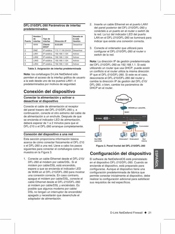
Figura 3. Panel frontal del DFL-210/DFL-260
WAN1
MÓDEM por cable/DSL
Ordenador2Ordenador1 Red interna
Conmutador
LAN1
Red DMZ (opcional)
DMZ
Internet
Inserte un cable Ethernet en el puerto LAN1 2. del panel posterior del DFL-210/DFL-260 y conéctelo a un puerto en el router o switch de la red. La luz del indicador LED del puerto LAN en el DFL-210/DFL-260 se iluminará para indicar que existe una conexión correcta.
Conecte el ordenador que utilizará para 3. configurar el DFL-210/DFL-260 al router o switch de la red.
Nota: La dirección IP de gestión predeterminada del DFL-210/DFL-260 es 192.168.1.1. Si está utilizando un router que usa DHCP, puede existir un conflicto si el router utiliza la misma dirección IP que el DFL-210/DFL-260. Si este es el caso, desconecte el DFL-210/DFL-260 del router y cambie la dirección IP de gestión del DFL-210/DFL-260, o bien, cambie los parámetros de DHCP en el router.
ES
PA
ÑO
L

22 D-Link NetDefend Firewall
Utilización de WebUIPara utilizar la WebUI, la estación de trabajo desde la que gestiona el dispositivo debe estar inicialmente en la misma subred que el dispositivo.
Para acceder al dispositivo con la WebUI:
Paso 1Conecte la estación de trabajo a la LAN1.
Paso 2Asegúrese de que la estación de trabajo está configurada con una dirección IP en la subred 192.168.1.0/24.
Nota:Desactive el software de bloqueo de elementos emergentes o añada la dirección IP de gestión https://192.168.1.1 a la lista de sitios permitidos.
Paso 3Inicie el explorador; introduzca la dirección IP para la interfaz de LAN1. (La dirección IP predeterminada de fábrica es https://192.168.1.1) y, a continuación, pulse Intro.
Nota: DFL-210/DFL-260 permite conexiones HTTP o HTTPS seguras desde cualquier host de gestión. No obstante, por motivos de seguridad, sólo se permite una conexión HTTPS segura de forma predeterminada. Para obtener más información acerca de cómo configurar los parámetros de las conexiones, consulte el Manual de usuario del cortafuegos.
Figura 4. Dirección del explorador
Explorador VersiónMicrosoft Internet Explorer
6.0 o superior
Mozilla Firefox 1.0 o superior
Navegador Netscape
8.0 o superior
Tabla 4. Compatibilidad del explorador
Paso 4Inicie sesión en la interfaz de web del cortafuegos NetDefend.
La información predeterminada de inicio de sesión es:
Nombre de usuario: adminContraseña: admin
Nota: El menú desplegable Idioma permite seleccionar un idioma para la WebUI. De forma predeterminada, el cortafuegos NetDefend sólo incluye de fábrica el inglés. Puede descargar archivos de idioma específicos desde la WebUI para obtener soporte en idiomas adicionales. En la actualidad, están disponibles archivos de idioma en japonés, ruso, chino simplificado y chino tradicional.
Utilización de una conexión de consola (RS-232 DCE)
El cortafuegos NetDefend proporciona un puerto serie RS-232 que admite la conexión a un ordenador o terminal de consola para supervisar y configurar el dispositivo. Este puerto utiliza un conector macho DB-9, que se utiliza como una conexión de equipo terminal de comunicación de datos (DCE).
Para utilizar la conexión del puerto de la consola, necesita el equipo siguiente:
Un terminal o un ordenador con un puerto 1. serie y capacidad para emular un terminal.
Un cable RS-232 con conector hembra DB-9. 2. (incluido en la caja)
Si su ordenador portátil o de sobremesa no 3. tiene un conector RS-232, será necesario un adaptador.
Nota: el DFL-210/DFL-260 no se envía con un adaptador RS-232.
Figura 5. Mensaje de autentificación
ES
PA
ÑO
L
D-Link NetDefend Firewall 23
Para establecer una conexión de consola:
Enchufe el extremo hembra del cable RS-232 1. suministrado directamente al puerto de la consola en el cortafuegos y apriete los tornillos sostenedores cautivos.
Conecte el otro extremo del cable a un 2. terminal o al conector serie de un ordenador que ejecute el software de emulación de terminal. Utilice los parámetros siguientes para el software de emulación de terminal:
Frecuencia de baudios: 9600 Bits de datos: 8 Paridad: ninguna Bits de parada: 1 Control de flujo: ninguno
Una vez configurado correctamente el terminal, 1. encienda el dispositivo. Aparecerá una secuencia de arranque en la pantalla del terminal.
Una vez completada la secuencia de 2. arranque, se muestra el indicador de comandos y el dispositivo está preparado para configurarse.
Después de la configuración inicial, consulte la documentación adjunta con formato PDF que encontrará en el CD maestro incluido, para obtener instrucciones detalladas acerca de la configuración del DFL-210/DFL-260.
Manual del usuario del cortafuegos D-Link NetDefendEste documento describe el funcionamiento y control general del firmware del NetDefendOS, sistema operativo registrado de D-Link que activa y controla el cortafuegos NetDefend. El Manual de usuario incluye instrucciones detalladas respecto a las tareas administrativas normales.
Registro del cortafuegos D-Link NetDefend Guía de referenciaEste documento describe todos los mensajes de registro que puede generar el NetDefendOS.
CLI del cortafuegos D-Link NetDefend Guía de referenciaEste documento describe todos los comandos de texto disponibles que se pueden utilizar con la consola RS-232 o la interfaz SSH para configurar el cortafuegos.
Finalización de la configuración
Además del manual de usuario, el CD maestro incluye también múltiples ejemplos de configuración del dispositivo. Existe ayuda adicional disponible a través de las oficinas de D-Link en todo el mundo, que aparecen enumeradas en el apéndice del Manual del usuario o en línea. Para obtener más información acerca de los productos de seguridad D-Link, visite el sitio web http://security.dlink.com.tw. Para obtener asistencia, visite el sitio web http://support.dlink.com.tw, que le redirigirá al sitio web de D-Link de su zona.
http://www.dlink.esAsistencia Técnica Telefónica de D-Link: +34 902 30 45 45 0,067 €/minDe Lunes a Viernes de 9:00 a 14:00 y de 15:00 a 18:00
Información adicional
Asistencia Técnica
ES
PA
ÑO
L

24 D-Link NetDefend Firewall
NOTES

In questo documento è descritta la procedura veloce per l'installazione del Firewall D-Link.DFL-210 / DFL-260
Documentazione disponibile anche su CD e tramite il sito Web D-Link
Guida di InstallazioneFirewall
Building Networks for People

26 D-Link NetDefend Firewall
Informazioni sulla guidaLa presente guida contiene istruzioni veloci per la configurazione del firewall D-Link DFL-210/DFL-260. Si noti che il modello acquistato potrebbe essere leggermente diverso da quello raffigurato nelle illustrazioni.
Disimballo del prodottoAprire la confezione e disimballarne il contenuto prestando particolare attenzione. Verificare il contenuto sulla base della lista riportata di seguito per accertarsi che tutti gli articoli siano presenti e integri. Se un articolo manca o è danneggiato, chiederne la sostituzione al rivenditore D-Link di zona.
Un (1) dispositivo DFL-210 o DFL-260 -NetDefend IPS o Firewall
Un (1) alimentatore a 5 V -
Un (1) cavo per connessione tramite console -(cavo RS-232)
Un (1) cavo Ethernet (UTP/diritto CAT5) -
Un (1) cavo Ethernet (UTP/cross CAT5) -
Un (1) CD-ROM contenente la documentazione -del prodotto in formato PDF
Un (1) pacchetto di abbonamento al servizio -IPS della durata di 12 mesi solo per DFL-260
Un (1) pacchetto di abbonamento al servizio -antivirus della durata di 12 mesi solo per DFL-260
Pannello frontale - DFL-210/DFL-260
Panoramica sul prodotto
Elemento Funzione DescrizioneA LED Power Indica che il dispositivo è
alimentato.
B LED Status Indica lo stato del sistema.
C LED WAN Indica lo stato della porta WAN.
D LED DMZ Indica lo stato della porta DMZ.
E LED LAN Indica lo stato della porta LAN.
LED di stato del dispositivo e LED delle porte Ethernet
I LED di stato del dispositivo forniscono informa-zioni sullo stato corrente del dispositivo. Quando il dispositivo è acceso, il LED Power e il LED Stauts passano da spento a verde fisso. L'avvio del dispositivo richiede circa un minuto. I LED Ethernet indicano lo stato di ciascuna porta Ethernet. Nella tabella 2 sono elencati il nome, il colore, lo stato e la descrizione di tutti i LED del dispositivo.
Nota: Se è necessario spegnere e riaccendere il dispositivo, si consiglia di attendere alcuni secondi tra un'operazione e l'altra.
Tabella 1. Descrizione del pannello frontale DFL-210/DFL-260
Nome Stato - DescrizionePower Spia spenta - Il dispositivo è spento.
Verde fisso - Il dispositivo è acceso.Status Spia spenta - Il dispositivo è spento o
in fase di avvio.Verde fisso - Il sistema funziona normalmente.Verde lampeggiante - Errore di sistema, ad esempio mancato aggior-namento del firmware.
WAN Spia spenta - Collegamento assente.Verde fisso - Collegamento presente.Verde lampeggiante - La porta invia o riceve dati.
DMZ Spia spenta - Il collegamento è assente o la porta funziona a 10 Mbps.Verde fisso - La porta funziona a 100 Mbps.Verde lampeggiante - La porta invia o riceve dati.
LAN 1-4 Spia spenta - Collegamento assente.Verde fisso - Collegamento presente e funzionante a 100 Mbps.Verde lampeggiante - La porta invia oriceve dati.
Tabella 2. Descrizione dei LED di stato del dispositivo
Figura 1. Pannello frontale DFL-210/DFL-260
D EA CB
ITA
LIA
NO

D-Link NetDefend Firewall 27
Impostazioni di interfaccia di default per DFL-210/DFL-260
Porta
Nome dell'inter-faccia
Tipo di inter-faccia Indirizzo IP
Basata sul Web Gestione
1 WAN Client DHCP
0.0.0.0/0 Disabilita
2 DMZ IP statico 172.17.100.254/24 Disabilita
3 LAN1 IP statico 192.168.1.1/24 Abilita
4 LAN2 IP statico 192.168.1.1/24 Abilita
5 LAN3 IP statico 192.168.1.1/24 Abilita
6 LAN4 IP statico 192.168.1.1/24 Abilita
Tabella 3. Assegnazione dell'interfaccia di default
Nota: per motivi di sicurezza i firewall D-Link NetDefend consentono l'accesso all'interfaccia grafica di amministrazione (via web browser) soltanto attraverso le porte lan.
Collegare un cavo Ethernet tra la porta WAN 1. del Firewall DFL-210/DFL-260 e il modem/router ADSL. Se il modem/router ADSL è alimentato, attendere che il LED WAN sul dispositivo DFL-210/DFL-260 sia accenda in modo da indicare il corretto collegamento. In caso contrario, spegnere il modem/router ADSL, collegare il cavo Ethernet tra il dispo-sitivo DFL-210/DFL-260 e il modem/router ADSL, quindi accendere il modem. Alcuni modem/router ADSL potrebbero non disporre di un interruttore di accensione/spegnimento, pertanto sarà necessario scollegare il cavo di alimentazione.
Collegare un'estremità di un cavo Ethernet 2. ad una porta LAN sul pannello posteriore del
Collegamento del cavo di alimentazione e accensione del dispositivo
Collegamento del dispositivo
Collegare un'estremità del cavo di alimentazione alla presa presente sul pannello posteriore del dispositivo DFL-210/DFL-260 e l'altra estremità a una presa a muro o a una presa multipla. Dopo l'accensione del LED di alimentazione è necessario attendere 1-2 minuti che il dispositivo DFL-210 o DFL-260 venga avviato completamente.
Collegamento del dispositivo in reteIn questa sezione vengono fornite informazioni di base sul collegamento fisico del dispositivo DFL-210 o DFL-260 a una rete. Attenersi alla procedura seguente per collegare il firewall come illustrato nella Figura 3.
dispositivo DFL-210/DFL-260 e l'altra estremità a una porta dell'hub o dello switch di rete. Il LED della porta LAN sul dispositivo DFL-210/DFL-260 si accenderà per indicare il corretto collegamento.
Collegare all'hub o allo switch di rete il computer 3. da utilizzare per configurare il dispositivo DFL-210/DFL-260.
Nota: l'indirizzo IP di default del dispositivo DFL-210/DFL-260 è 192.168.1.1. Se si dispone di un router, potrebbe verificarsi un conflitto se utilizza lo stesso indirizzo IP del DFL-210/DFL-260. In tal caso, scollegare il DFL-210/DFL-260 dal router e modificare l'indirizzo IP del DFL-210/DFL-260 oppure le impostazioni nel router.
Il software NetDefendOS è preinstallato nel dispositivo DFL-210/DFL-260. All'accensione del dispositivo è pronto per essere configurato. Il dispositivo prevede una configurazione di default che ne consente il primo utilizzo, tuttavia è neces-sario specificare ulteriori impostazioni di configu-razione a seconda dei requisiti specifici della rete.
Configurazione del dispositivo
Figura 3. Pannello frontale DFL-210/DFL-260
WAN1
Modem cavo/DSL
Computer2Computer1 Rete interna
Switch
LAN1
Rete DMZ (opzionale)
DMZ
Internet
ITALIA
NO

28 D-Link NetDefend Firewall
Utilizzo dell'interfaccia utente WebPer utilizzare l'interfaccia utente Web, la workstation da cui si gestisce il dispositivo deve appartenere inizialmente alla stessa subnet del dispositivo.
Per accedere al dispositivo tramite l'interfaccia utente Web:
Passo 1Collegare la workstation su LAN1.
Passo 2Verificare che la workstation sia configurata con un indirizzo IP statico nella subnet 192.168.1.0/24.
Nota:disabilitare il software per il blocco dei popup oppure aggiungere l'indirizzo IP di gestione https://192.168.1.1 all'elenco degli indirizzi consentiti dal software per il blocco dei popup.
Passo 3Avviare il browser, quindi immettere l'indirizzo IP per l'interfaccia LAN1. L'indirizzo IP di default è https://192.168.1.1. Premere Invio.
Nota: il dispositivo DFL-210/DFL-260 consente di stabilire connessioni HTTP o HTTPS protette da qualsiasi host di gestione. Per motivi di sicurezza, per default è consentita una sola connessione HTTPS protetta. Per ulteriori informazioni, sulla configurazione delle impostazioni per le connes-sioni, fare riferimento al manuale dell'utente del firewall.
Figura 4. Indirizzo del browser
Browser VersioneMicrosoft Internet Explorer
6.0 o successiva
Mozilla Firefox 1.0 o successiva
Netscape Navigator 8.0 o successiva
Tabella 4. Compatibilità dei browser
Passo 4Accedere all'interfaccia Web di NetDefend Firewall.
Le informazioni di default per l'accesso sono le seguenti:
Username: adminPassword: admin
Nota: il menu a discesa della lingua consente di selezionare una lingua per l'interfaccia utente Web. Per default, NetDefend Firewall include solo l'inglese. Per usufruire di ulteriore supporto, è possibile caricare file di lingue specifiche dall'in-terfaccia utente Web. Al momento sono disponibili i file per le lingue giapponese, russo, cinese semplificato e cinese tradizionale.
Utilizzo di una connessione tramite console (DCE RS-232)
Il dispositivo NetDefend Firewall include una porta seriale RS-232 per il collegamento a un computer o a un terminale di console utilizzabile per il monitoraggio e la configurazione del dispositivo. Tale porta utilizza un connettore DB-9 maschio, implementato come connessione DCE (Data Communication Terminal Equipment).
Per utilizzare la connessione tramite la porta console, è necessario disporre di quanto segue:
Terminale o computer dotato di porta seriale e 1. della funzione per l'emulazione di terminale.
Cavo RS-232 con connettore DB-9 femmina 2. (incluso nella confezione).
Se il laptop o il PC non dispone di un connettore 3. RS-232, è necessario un adattatore.
Nota: con il dispositivo DFL-210/DFL-260 non viene fornito alcun adattatore RS-232.
Figura 5. Messaggio di autenticazione
ITA
LIA
NO

D-Link NetDefend Firewall 29
Per stabilire una connessione tramite console:
Collegare l'estremità femmina del cavo RS-232 1. fornito direttamente alla porta della console sul firewall.
Collegare l'altra estremità del cavo a un 2. terminale o al connettore seriale di un computer che esegue il software di emula-zione del terminale. Utilizzare le seguenti impostazioni per il software di emulazione del terminale:
Velocità in baud: 9600 Bit di dati: 8 Parità: Nessuna Bit di stop: 1 Controllo del flusso: Nessuno
Dopo aver configurato correttamente il 1. terminale, accendere il dispositivo. Sullo schermo del terminale verrà visualizzata una sequenza di avvio.
Al termine della sequenza di avvio, viene 2. visualizzato il prompt dei comandi a indicare che il dispositivo è pronto per essere configurato.
Dopo l'impostazione iniziale, fare riferimento ai manuali in formato PDFdisponibili nel CD principale per istruzioni dettagliate sulla configurazione del dispositivo DFL-210/DFL-260.
Manuale dell'utente di D-Link NetDefend FirewallIn questo documento sono descritte le procedure di utilizzo generale e i comandi del firmware NetDefendOS, il sistema operativo proprietario di D-Link che consente di gestire e controllare il firewall NetDefend. Questo manuale include istru-zioni dettagliate sulle attività amministrative standard.
Log di D-Link NetDefend Firewall Guida di riferimentoIn questo documento sono descritti tutti i messaggi del log che possono essere generati da NetDefendOS.
CLI di D-Link NetDefend Firewall Guida di riferimentoIn questo documento sono descritti tutti i comandidi testo disponibili che possono essere utilizzati con la console RS-232 o con l'interfaccia SSH per configurare il firewall.
Completamento della configurazione
Oltre al manuale dell'utente, sul CD principale sono inclusi molti esempi di configurazione del dispositivo. Per ulteriore supporto è possibile rivolgersi agli uffici D-Link il cui elenco è riportato nell'appendice del manuale dell'utente o è dispo-nibile in linea. Per ulteriori informazioni sui prodotti D-Link, visitare il sito Web http://security.dlink.com.tw. Per assistenza, visitare il sito Web http://support.dlink.com.tw, da cui è possibile accedere al sito Web D-Link per il proprio paese.
http://www.dlink.it/supportSupporto Tecnico dal lunedì al venerdì dalle ore 9.00 alle ore 19.00 con orario continuatoTelefono: 199400057
Ulteriori informazioni
Supporto Tecnico
ITALIA
NO

30 D-Link NetDefend Firewall
FCC EMI for Class A Statements
CE WARNING Statement
Battery Caution:
VCCI WARNING Statement
Appendix: Product Statement
FCC Interference InformationThis device complies with Part 15 of the FCC Rules. Operation is subject to the following two conditions:(1) This device may not cause harmful inter-ference, and (2) This device must accept anyinterference received, including interference that may cause undesired operation.
This equipment has been tested and found to comply with the limits for a Class A digitaldevice, pursuant to Part 15 of the FCC Rules. These limits are designed to provide reasonable protection against harmful interference in a residential installation. This equipment generates, uses, and can radiate radio frequency energy and, if not installed and used in accordance with the instruction manual, may cause harmful interface to radio communication. Operation of this equipment in a residential area is likely to cause harmful interface in which cause the user will be required to correct the interface at his own expense.
FCC CAUTION:Any changes or modifications not expressly approved by the party responsible for compliance could void the user's authority to operate this equipment.
CE EMI CLASS A WARNINGThis is a class A product. In a domestic environment this product may cause radio interference in which case the user may be required to take adequate measures.
CAUTION: Risk of Explosion if Battery is replaced by an Incorrect Type. Dispose of Used Batteries According to the Instructions.

D-Link NetDefend Firewall 31
NOTES

Ver. 2.00(E)2009/06/23
086W020000040
![gfkmf–gf]S;fg lx;fj bf]>f] q}dfl;s klxnf] q}dfl;s](https://static.fdocuments.us/doc/165x107/61960cc271529b35ed7b850f/gfkmfgfsfg-lxfj-bfgtf-qdfls-klxnf-qdfls.jpg)