Quick Guide on CDEGS CR
28
1 This guide is for MultiGround package which is made up of 3 engineering modules RESAP MALT FCDIST CDEGS is an Integrated Software for Power System Grounding/Earthing, Electromagnetic Fields and Electromagnetic Interference supplied by Safe Engineering Services and technologies ltd. For more information and deep understanding of the Package go to www.sestech.com User Guide for Current Distribution, Electromagnetic Fields, Grounding and Soil Structure Analysis (CDEGS) Software Package
description
Quick Guide on CDEGS CR
Transcript of Quick Guide on CDEGS CR

1
This guide is for MultiGround package which is made up of 3 engineering modules
RESAP MALT FCDIST
CDEGS is an Integrated Software for Power System Grounding/Earthing, Electromagnetic Fields and Electromagnetic Interference supplied by Safe Engineering Services and technologies ltd.
For more information and deep understanding of the Package go to www.sestech.com
User Guide for Current Distribution, Electromagnetic Fields, Grounding and Soil Structure Analysis (CDEGS) Software Package

2
Create file –
Start program
Enter data measured on site
Create multi layer soil model (layer
thickness and resistivities) to be used
in simulations
Enter preliminary (or existing) earthmat grid
(as per earthmat layout drawing)
Enter parameters for simulation- Fault current,
Conductor type
Enter information for connected power lines
(that will share the fault current)
Run simulation to determine GPR, step and touch voltages
CDEGS Design Flowchart

3
Start up
Job ID drop down menu appears
NB: All projects for a particular substation must be saved in the same Substation folder for record purposes. Look at the latest job on that particular sub
Create Working Directory
D:User\Data\Substation Name\Project Name
Once complete click OK
Open CDEGS from Start Program or desktop short cut

4
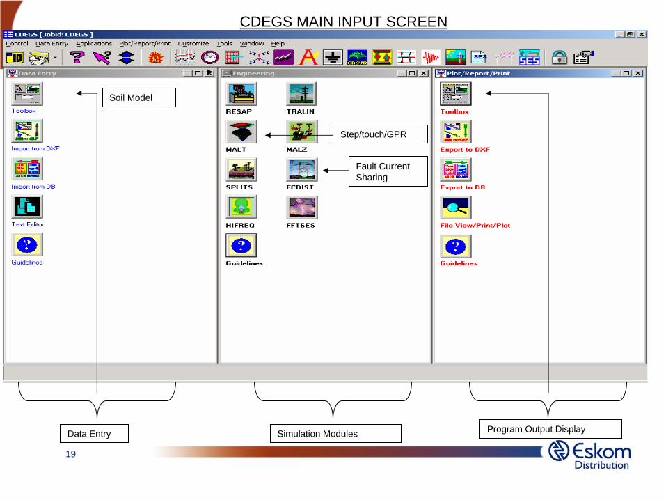
Data Entry Simulation Modules Program Output Display
Soil Model
Step/touch/GPR
Fault Current Sharing
CDEGS Main Input Screen

5
To enter data, click on Toolbox in the Data Entry window. The following menu will appear
1. RESAP
Module used for Soil Resistivity Analysis from the field measurements
> Click on Toolbox under Data Entry Toolbar > Click on RESAP > Window on Slide number 6 Appears
2. MALT
Module used for Low Frequency Grounding / Earthing Analysis
> Click on Toolbox under Data Entry Toolbar>Click on RESAP > Window on Slide number 10 Appears
3. FCDIST
Module used to determine the sharing in dissipation of the fault current between the substation electrode and the connected power line shield wires > Click on Toolbox under Data Entry Toolbar>Click on FCDIST > Window on Slide number Appears
Modules in CDEGS
We are currently using only the three modules highlighted below:

6
Now, click on Measurements to input field data
In TOOLBOX Click on RESAP The following menu will appear
1. Select Job ID
2. Ensure System of Units is Metric
Resap

7
Specifying Measurement Conditions:
1. Werner, Long Filter
2. Resistance
3. Ignore Probe Depth
Entering Field Data
• Probe Spacing in meters
• Apparent Resistance values in Ohms
Note: The minimum requirement is 2 sets of soil Resistivity measurements must be taken. Both sets of measurements must be entered
When complete, click on “OK” The program will take you back to Resap
Field Data
8
Defining the Soil Model
If Soil Resistivity and Thickness are not known
1. Determine Automatically
2. Horizontal Layers
If Soil Resistivity and Thickness are known
1. User Defined
2. Horizontal Layers
In RESAP window Click on Soil Types. The following menu will appear

9
Click OK / Submit to exit the RESAP window and go back to Toolbox
Exiting Resap

10
In TOOLBOX Click on MALT. The following window will appear
Now, click on System to CREATE or IMPORT the Grid and Define Grid Energization. See next page
1. Select Job ID
2. Ensure System of Units is Metric
3. Radius in meters
Malt

11
CREATE or IMPORT the Grid and Define Grid Energization
2.Put in the coordinates of the grid Conductors and
the Conductor Radius = 0.05m
1. Select Main Ground
3. Select Current (Amps)
4. Enter Fault Current Magnitude
which will be shared at a later stage (FCDIST)Click on Ampacity for Conductor Ampacity Calculation
12
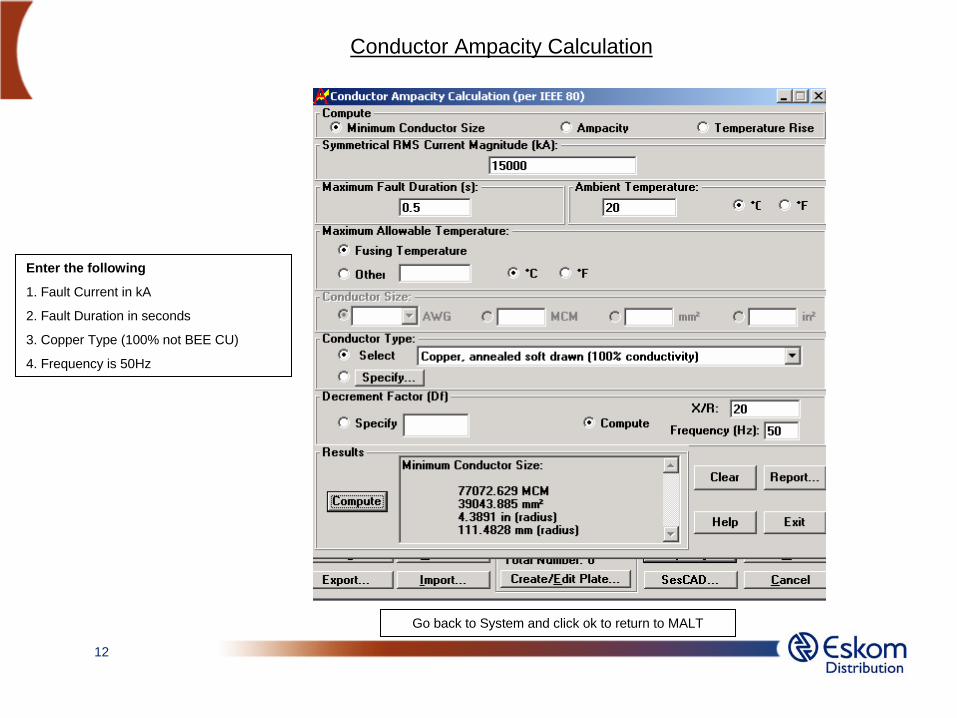
Conductor Ampacity Calculation
Enter the following
1. Fault Current in kA
2. Fault Duration in seconds
3. Copper Type (100% not BEE CU)
4. Frequency is 50Hz
Go back to System and click ok to return to MALT
13
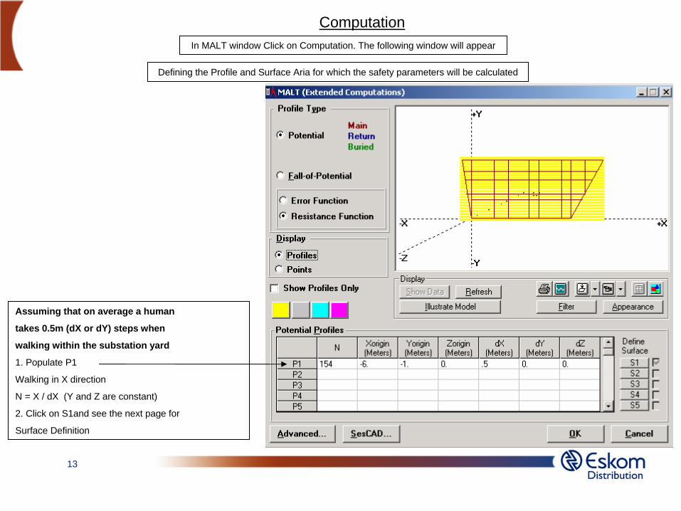
In MALT window Click on Computation. The following window will appear
Defining the Profile and Surface Aria for which the safety parameters will be calculated
Assuming that on average a human
takes 0.5m (dX or dY) steps when
walking within the substation yard
1. Populate P1
Walking in X direction
N = X / dX (Y and Z are constant)
2. Click on S1and see the next page for
Surface Definition
Computation

14
Defining the Profile and Surface Aria
This window appears after clicking on S1
1. Populate the Surface details with Y being
a variable and then click ok
Click OK to return to Computation and OK to return to MALT and then OK /Submit to return to Toolbox
Walking in the Y direction
N = Y / dY (X and Z are constant)
15
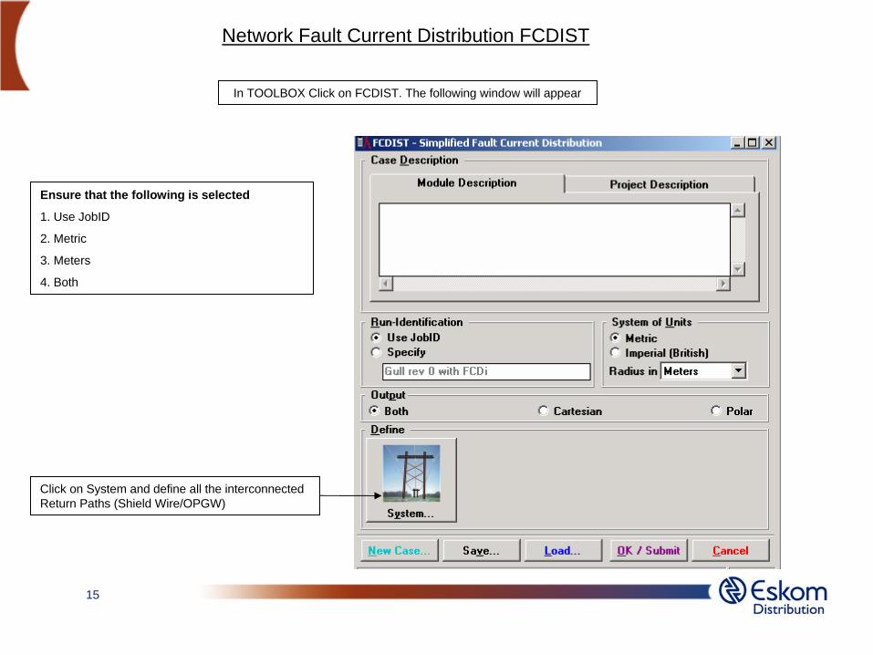
In TOOLBOX Click on FCDIST. The following window will appear
Ensure that the following is selected
1. Use JobID
2. Metric
3. Meters
4. Both
Click on System and define all the interconnected Return Paths (Shield Wire/OPGW)
Network Fault Current Distribution FCDIST
16
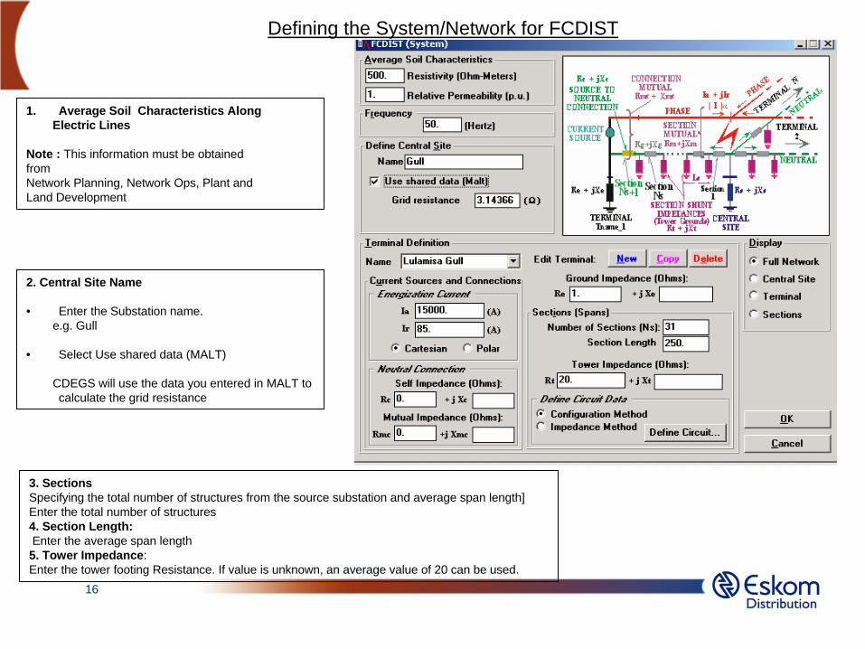
Defining the System/Network for FCDIST
3. SectionsSpecifying the total number of structures from the source substation and average span length]Enter the total number of structures 4. Section Length:Enter the average span length5. Tower Impedance: Enter the tower footing Resistance. If value is unknown, an average value of 20 can be used.
1. Average Soil Characteristics Along Electric Lines
Note : This information must be obtained from Network Planning, Network Ops, Plant and Land Development
2. Central Site Name
• Enter the Substation name.e.g. Gull
• Select Use shared data (MALT)
CDEGS will use the data you entered in MALT to calculate the grid resistance

17
Define Circuit [ Specifying the height and electricalcharacteristic of the shield wire, as well as the height of the phase conductor where a phase-to-earth fault occurs]
Defining the Circuit
Click on Define Circuit in System window and this window will appear.
Click Import From Database to select the shield Wire from the list(See next page)

18
Importing Shield Wire and/or OPGW from Database
1.Click ok to return to Define Circuit window and ok again to return to System window
2.On System window, click NEW if there is more than 1 Terminal go over the process for the new line.
3. When you are done click OK /Submit on System window to return to Toolbox
4.Click Submit All in the Toolbox window to return to CDEGS Main window
(see page 18)
19
Data Entry Simulation Modules Program Output Display
Soil Model
Step/touch/GPR
Fault Current Sharing
CDEGS MAIN INPUT SCREEN

20
Running Simulation in Engineering window
1. Click on RESAP and then OK once the program has completed Simulation
2. Click on MALT and then OK once the program has completed Simulation
3. Click on FCDIST and then OK once the program has completed Simulation
21
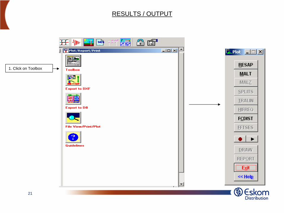
RESULTS / OUTPUT
1. Click on Toolbox
22
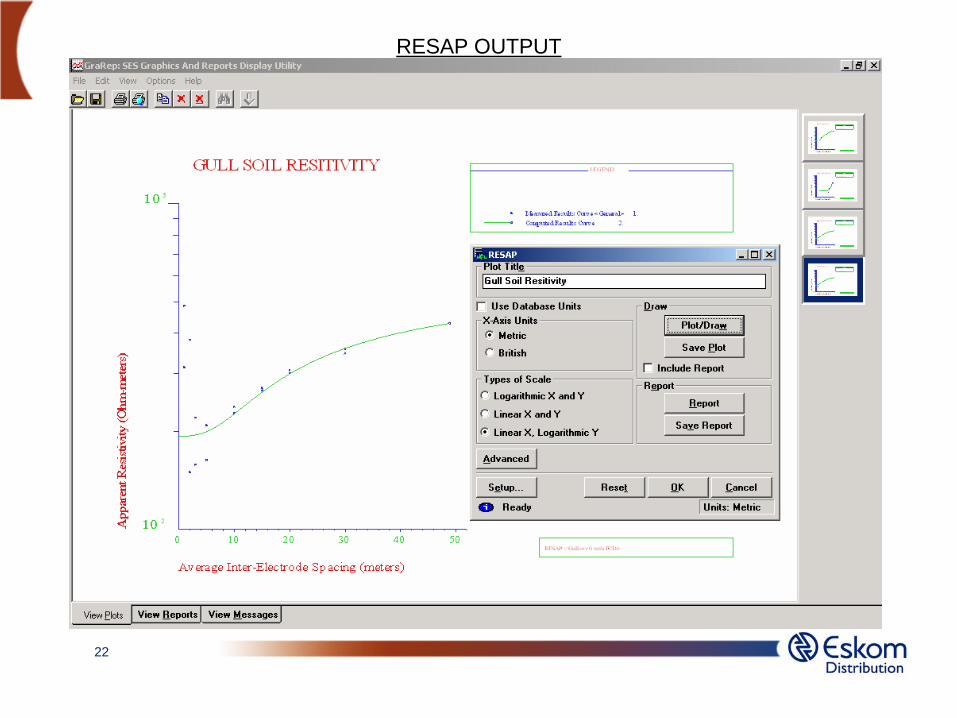
RESAP OUTPUT
23
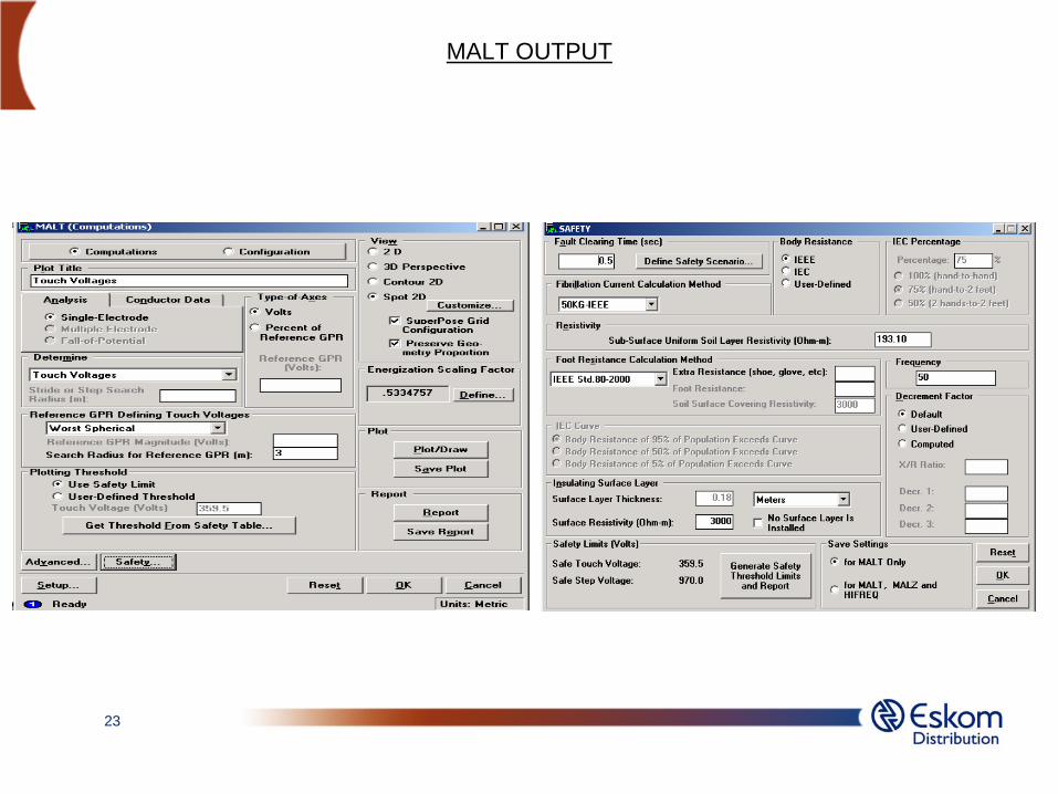
MALT OUTPUT
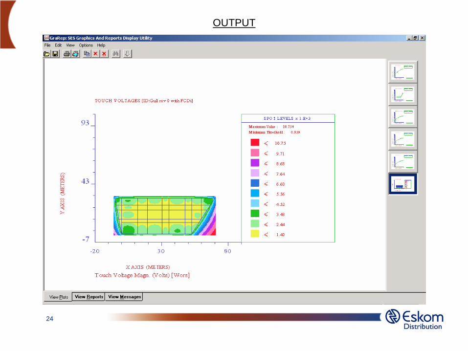
24
OUTPUT

25
OUTPUT

26
REPORT
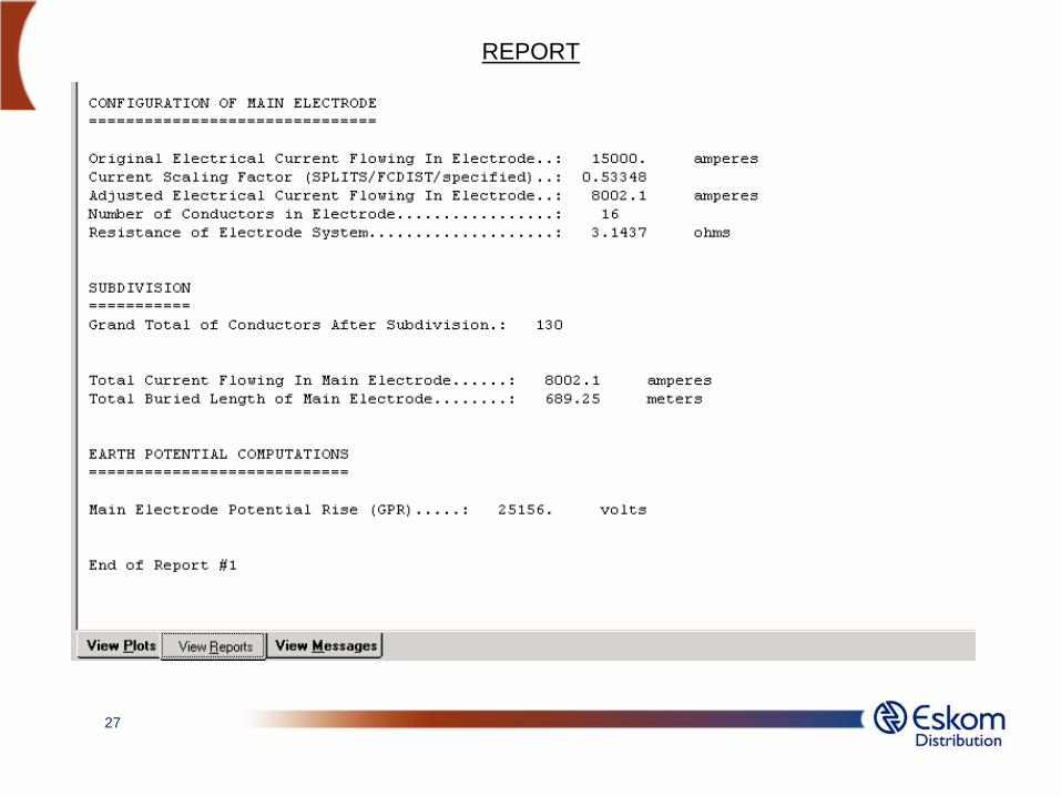
27
REPORT

28
Analyse the results and take corrective measures as per Substation Earthing Standard if any safety requirement is not met
Output


![Sizes Payload Compensation path XY up to 20 kg - Comoso · Compensation path XY ... Material CR CR CR CR NBR CR CR CR CR CR CR NBR NBR NBR NBR NBR ... Bending [Nm/rad] 474 552 1025](https://static.fdocuments.us/doc/165x107/5af1b3557f8b9ac57a903b0d/sizes-payload-compensation-path-xy-up-to-20-kg-path-xy-material-cr-cr-cr-cr.jpg)