QUESTIONS - Kentucky Transportation Cabinet Manual/DR 50… · between the ditch and top of cut, if...
47
DR-501 02/10 DR 501 Page 1 of 2 Chapter Open Channels Subject Introduction Drainage DR 501-1 OPEN CHANNEL FLOW Open-channel systems will often be used to collect and convey storm water. The open channels discussed in this chapter range from small manmade roadside channels that convey small local drainage areas to large natural channels that act as the primary storm water conveyance for a large geographic areas. An open channel is defined as any conduit in which liquid flows with a free surface such as a stream, roadside ditch, depressed median, slope flume, or pipe flowing part full. Although open channel hydraulic principles apply to both roadway ditches and stream channels, the analysis techniques and assumption are different for each of them. DR 501-2 GENERAL DESIGN CONSIDERATIONS The following general guidelines shall be considered in open channel design: Open channels shall be designed such that elevations of the water surface in the channel do not cause undue flooding of the highway facility or damage to adjacent property. Open channels shall be designed to be stable against erosive forces of water. Use of grass lined channels shall be maximized as a drainage conveyance system due to their positive impacts on water quality. The use of turf reinforcing mats should be considered when natural vegetation alone will not withstand the expected erosive forces. DR 501-3 ROADSIDE DITCHES Roadside ditches include the manmade channels used to convey local drainage to a larger drainage system. Roadside ditches: Are constructed channels with regular geometric cross sections uniformly shaped May be lined with a protective material to prevent erosion Are generally designed and analyzed assuming steady, uniform flow assumptions
Transcript of QUESTIONS - Kentucky Transportation Cabinet Manual/DR 50… · between the ditch and top of cut, if...

DR-501
02/10 DR 501 Page 1 of 2
Chapter
INTRODUCTION
Subject
Purpose of the Guidance Manual
Materials Field
Sampling
Chapter
Open Channels
Subject
Introduction
Drainage
DR 501-1 OPEN CHANNEL FLOW Open-channel systems will often be used to collect and convey storm water. The
open channels discussed in this chapter range from small manmade roadside channels that convey small local drainage areas to large natural channels that act as the primary storm water conveyance for a large geographic areas.
An open channel is defined as any conduit in which liquid flows with a free
surface such as a stream, roadside ditch, depressed median, slope flume, or pipe flowing part full.
Although open channel hydraulic principles apply to both roadway ditches and
stream channels, the analysis techniques and assumption are different for each of them.
DR 501-2 GENERAL DESIGN CONSIDERATIONS
The following general guidelines shall be considered in open channel design:
Open channels shall be designed such that elevations of the water surface in the channel do not cause undue flooding of the highway facility or damage to adjacent property.
Open channels shall be designed to be stable against erosive forces of water.
Use of grass lined channels shall be maximized as a drainage conveyance system due to their positive impacts on water quality. The use of turf reinforcing mats should be considered when natural vegetation alone will not withstand the expected erosive forces.
DR 501-3 ROADSIDE DITCHES
Roadside ditches include the manmade channels used to convey local drainage to a larger drainage system. Roadside ditches:
Are constructed channels with regular geometric cross sections uniformly
shaped May be lined with a protective material to prevent erosion Are generally designed and analyzed assuming steady, uniform flow
assumptions

OPEN CHANNELS
Introduction DR-501
02/10 DR 501 Page 2 of 2
KYTC further classifies roadside ditches according to their use. This will be discussed later in this chapter.
DR 501-4 STREAM CHANNELS
Stream channels are generally naturally shaped channels that usually drain larger areas than roadside ditches. Steam channels are:
usually natural channels with their size and shape determined by natural
forces, usually compound in cross section with a main channel for conveying low
flows and a floodplain to transport flood flows, and usually shaped in cross section and plan form by the long-term history of
sediment load and water discharge that they experience. Usually analyzed with step – backwater techniques.
This manual addresses stream channel design only as it pertains to hydraulic considerations for highway structures or minor disturbances to stream channels to facilitate highway construction. Channel restoration and natural channel design are within the purview of the Division of Environmental Analysis. As will be seen in DR 506, certain impacts to stream channels require the involvement of the Division of Environmental Analysis.

DR-502
02/10 DR 502 Page 1 of 3
Chapter
INTRODUCTION
Subject
Purpose of the Guidance Manual
Materials Field
Sampling
Chapter
Open Channels
Subject
Channel Classifications
Drainage
DR 502-1 STREAM CHANNELS
Stream channels, as classified in KYTC policy, are essentially natural channels. Stream channels include any drainage feature that is currently or ever has been a natural feature. Stream channels are generally larger than roadside ditches and are usually associated with large hydraulic structures such as bridges and culverts. However, stream channels can include very small channels that are not wet year round. Stream channels are sometimes relocated or modified to accommodate the construction of highways. Although there are cases where changes to stream channels will be necessary, this practice should be avoided if possible.
DR 502-2 ROADSIDE DITCHES
Roadside ditches are manmade channels constructed to convey water. There are several different types of roadside ditches used on KYTC project. Roadside ditches are usually have a “v” or flat bottom shape.
NORMAL DITCHES Normal ditches refer to ditches that are constructed as a continuous grading operation with the roadway. The location and grade of normal ditches is controlled by the typical section and the horizontal and vertical alignment of the roadway. Normal ditches are usually associated with cut sections and run parallel to the highway. SPECIAL DITCHES Special ditches are used where the normal ditch geometry must vary from the typical section for hydraulic purposes. If a ditch is constructed wider, deeper, on a different grade, or is shaped differently than the typical roadway section normal ditch, then it is classified as a special ditch. SURFACE DITCHES
These ditches are formed by excavating the ditch shape into the existing ground line surface. Surface ditches are primarily used at the base of fills to collect to roadway drainage or to intercept off site drainage before it reaches the toe of the

OPEN CHANNELS
Channel Classifications DR-502
02/10 DR 502 Page 2 of 3
fill. A flat bottom shape is generally used for surface ditches because of ease of construction. Judgment must be used in placing surface ditches in close proximity to the toe of slope for highway fills. INTERCEPTOR DITCHES
Interceptor ditches are used to intercept water and convey it in a controlled manner. Interceptor ditches are used for vaying reasons such as:
Divert water around a project
Separate clean off site water from sediment laden construction runoff
Collect water at the top of cut slopes to prevent erosion of the slope
Divert water to a controlled outlet point.
DR 502-3 ROADSIDE DITCH GEOMETRY CONSIDERATIONS
The following guidelines are provided for guidance in determining the geometry of roadside ditches.
Maintain grades of at least 0.5% Side slopes should not exceed the recommendations of the projects
geotechnical reports. For ditches in close proximity to the top of cuts, provide 10’ of space
between the ditch and top of cut, if right of way is available. For ditches running along the toe of a fill, provide adequate distance
between the toe of fill and the ditch. If the ditch carries large amounts of runoff it is desirable to place them 10’ from the toe of the fill.
For ditches located in close proximity to the pavement structure, make the ditch deep enough to provide subgrade drainage for the pavement structure.
Aggregate linings should follow thickness recommendations specified in DR 500.
Avoid sharp bends and abrupt grade changes that could lead to erosion of the channel.
Roadside safety considerations should be considered when determining the geometry of ditches and channels. See the HD 800 and the AASHTO Roadside Design Guide for more information. b
DR 502-4 BID ITEM REQUIREMENTS FOR ROADSIDE DITCHES The work necessary to construct all roadside ditches is measured and payed under the bid item “Roadway Excavation” for ditches contructed in cut sections. See section 204 of the Standard Specifications for Road and Bridge Construction for more information. Ditches that are constructed in fill sections are measured and payed by the bid item “Embankment in Place.” See section 206 of the Standard Specifications for Road and Bridge Construction for more information. The calculated quantities of Roadway Excavation and Embankment in Place necessary to construct roadside ditches are included in the total earthwork

OPEN CHANNELS
Channel Classifications DR-502
02/10 DR 502 Page 3 of 3
quantities for the project. However as noted below, some ditches require these quantities be shown separately in cross sections.
DR 502-5 PLAN REQUIREMENTS FOR ROADSIDE DITCHES
It is not required to shown ditches that can be constructed as a continuous grading operation with the roadway in plan and profile views. This primarily includes normal ditches as described above. All other ditches shall be shown in plan and profile views. All ditches are shown in cross sections. Since surface and interceptor ditches require a separate grading operation, their quantities shall be shown separately in the cross sections. For more details on plan requirements see DR 1103.

DR-503
02/10 DR 503 Page 1 of 10
Article I.
Section 1.01
Section 1.02 Chapter
INTRODUCTION
Section 1.03
Section 1.04 Subject
Purpose of the Guidance Manual
Materials Field
Sampling
Section 1.05
Chapter
Open Channels
Section 1.06
Subject
Channel Hydraulics
Drainage
DR 503-1 OPEN CHANNEL FLOW TYPES
The classification of open channel flow can be summarized as follows Steady Flow
o Uniform Flow o Non-uniform Flow
Gradually Varied Flow Rapidly Varied Flow
Unsteady Flow
o Unsteady Uniform Flow (rare) o Unsteady Non-uniform Flow
Gradually Varied Unsteady Flow Rapidly Varied Unsteady Flow
Steady, uniform flow and steady, non-uniform flow are the most common types of flow encountered in highway engineering hydraulics. The following definitions apply to the open channel flow classification outline listed above: Steady flow - A flow in which the flow rate or quantity of fluid passing a given
point per unit of time remains constant. Uniform flow - Flow of constant cross section and average velocity through a
reach of channel during an interval of time. Non uniform flow - A flow in which the velocities vary from point to point along
the stream or conduit Steady uniform flow - the quantity and velocity are the same at all points
along the channel. For this condition the cross section of flow must be constant, such as ditches and excavated channels with unvarying cross sections. Steady, uniform flow is generally analyzed with single-section methodologies
Steady non uniform flow - the quantity of flow is constant at any point, but the
velocity varies. This type of flow is most common in natural streams and is

OPEN CHANNELS
Channel Hydraulics DR-503
02/10 DR 503 Page 2 of 10
commonly encountered in the design of large highway stream crossings. By subdividing the channel reach, the available flow formulas, which assume steady uniform flow, may be used to analyze the reach. Steady, non-uniform flow is analyzed with step-backwater methodologies.
Laminar or streamline flow - all particles move parallel to each other Turbulent flow - swirls and eddies are prevalent
DR 503-2 EQUATION OF CONTINUITY
If steady flow exists throughout a reach of any channel there is continuity of discharge or, as commonly stated, continuity of flow. The mean velocities at all cross sections having equal areas are equal. If the areas are not equal, the velocities are inversely proportional to the areas of the respective cross sections. Thus, A1V1 and A2V2 are the respective products of area and mean velocity at any two cross sections in an open channel where continuity of flow exists.
Equation 503-1 Continuity Equation
A1V1 = A2V2 and V1/V2 = A2/A1
DR 503-3 HYDRAULIC RADIUS
The hydraulic radius has a dimension of depth, and for very wide channels with shallow depths, the value approaches average depth.
Equation 503-2 Hydraulic Radius R =A/P
R = hydraulic radius A = area of cross section of flow P = length of wetted perimeter
DR 503-4 ENERGY
According to Bernoulli's conservation of energy principal, the total energy head at an upstream cross section is equal to the total energy head at a downstream section plus the energy head loss between the two sections. Energy of the water may be of two forms: potential energy due to depth of the water and elevation above some zero datum plane and kinetic energy due to velocity. Potential energy is represented by potential head depth plus height (y + Z), above the zero datum plane, in feet; and kinetic energy is represented by the velocity head (V2 /2g), in feet. Referring to Figure 503-1, the total head at point 1 in a stream is equal to the total head at point 2 in the stream plus head losses occurring between the two points:
Equation 503-3 Energy Equation y1 + V1
2/2g + Z1 = y2 + V22/2g + Z2 + hL

OPEN CHANNELS
Channel Hydraulics DR-503
02/10 DR 503 Page 3 of 10
DR 503-5 SPECIFIC ENERGY
It is often convenient to consider the energy content with respect to the channel bottom. This is called the specific energy, or specific head, and is equal to the depth of the water plus the velocity head (y + V2/2g). The slope of the energy line is a measure of the friction slope or rate of energy head lost due to friction(S = hL /L). For small channels, the specific energy is constant. Thus the friction loss, hf is equal to the elevation difference between the two points in the channel (Z1 - Z2).
Figure 503-1 Total Energy Diagram
For large channels, the specific energy cannot be assumed constant and a standard step backwater procedure must be used. By trial and error, the above energy equation is balanced using the Manning's equation below.
DR 503-6 MANNING’S EQUATION
Manning's formula for computing flow in open channels is widely used because of its simplicity:
Equation 503-4 Manning’s Equation V = (1.49/n)(R0.67)(S0.5)

OPEN CHANNELS
Channel Hydraulics DR-503
02/10 DR 503 Page 4 of 10
V = velocity, feet per second R = hydraulic radius, feet S = slope of channel, feet per feet n = roughness coefficient The roughness coefficient, n, accounts for the character of: Stream or channel bed Banks or side slopes Vegetation both in channel and on banks
DR 503-7 MANNING’S N & RELATIVE ROUGHNESS
The selection of an appropriate Manning's n value for design purposes is often based on observation and experience. In theory, Manning’s n is dependent on the surface roughness of the material the water is flowing over or through and the depth of flow over the surface. The ratio of the roughness of the material to the depth of flow is termed relative roughness. For shallow flow over rough surfaces the relative roughness is high and the Manning’s n value can vary significantly with depth as shown in Table 505-1. Shallow flow occurs when the height of the roughness of the surface is about one-tenth or more of the depth of flow.
Values of n for use in Manning's formula for excavated or natural streams are given in Table 503-1 below. More information on Manning’s n for lined channels can be found in DR 505.
Table 503-1 Values of roughness coefficient “n” (uniform flow) Type of Channel and Description Minimum Normal Maximum
EXCAVATED OR DREDGED
A. Earth, straight and uniform 0.016 0.018 0.020
1. Clean, recently completed 0.018 0.022 0.025
2. Clean, after weathering 0.022 0.025 0.030
3. Gravel, uniform section, clean 0.022 0.027 0.033
B. Earth, winding and sluggish
1. No vegetation 0.023 0.025 0.030
2. Grass, some weeds 0.025 0.030 0.033
3. Dense weeds or aquatic plants in deep channels 0.030 0.035 0.040
4. Earth bottom and rubble sides 0.025 0.030 0.035
5. Stony bottom and weedy sides 0.025 0.035 0.045
6. Cobble bottom and clean sides 0.030 0.040 0.050
C. Dragline-excavated or dredged
1. No vegetation 0.025 0.028 0.033
2. Light brush on banks 0.035 0.050 0.060
D. Rock cuts
1. Smooth and uniform 0.025 0.035 0.040
2. Jagged and irregular 0.035 0.040 0.050
E. Channels not maintained, weeds and brush uncut
1. Dense weeds, high as flow depth 0.050 0.080 0.120

OPEN CHANNELS
Channel Hydraulics DR-503
02/10 DR 503 Page 5 of 10
Table 503-1 Values of roughness coefficient “n” (uniform flow) Type of Channel and Description Minimum Normal Maximum
2. Clean bottom, brush on sides 0.040 0.050 0.080
3. Same, highest stage of flow 0.045 0.070 0.110
4. Dense brush, high stage 0.080 0.100 0.140
NATURAL STREAMS
A. Minor Streams (top width at flood stage < 100 feet)
1. Streams on Plain
a. Clean, straight, full stage, no rifts or deep pools 0.025 0.030 0.033
b. Same as above, but more stones and weeds 0.030 0.035 0.040
c. Clean, winding, some pools and shoals 0.033 0.040 0.045
d. Same as above but some weeds and stones 0.035 0.045 0.050
e. Same as above, lower stages, more ineffective slopes and sections
0.040 0.048 0.055
f. Same as 4, but more stones 0.045 0.050 0.060
g. Sluggish reaches, weedy, deep pools 0.050 0.070 0.080
h. Very weedy reaches, deep pools, floodways with heavy stand of timber and underbrush
0.075 0.100 0.150
2. Mountain streams, no vegetation in channel, banks usually steep, trees and brush along banks submerged at high stages
a. Bottom: gravels, cobbles, and few bolders 0.030 0.040 0.050
b. Bottom: cobbles with large bolders 0.040 0.050 0.070
B. Flood Plains
1. Pasture, no brush
a. Short grass 0.025 0.030 0.035
b. High grass 0.030 0.035 0.050
2. Cultivated area
a. No crop 0.020 0.030 0.040
b. Mature row crops 0.035 0.035 0.045
c. Mature field crops 0.030 0.040 0.050
3. Brush
a. Scattered brush, heavy weeds 0.035 0.050 0.070
b. Light brush and trees in winter 0.035 0.050 0.060
c. Light brush and trees in summer 0.040 0.060 0.080
d. Medium to dense brush in winter 0.045 0.070 0.110
e. Medium to dense brush in summer 0.070 0.100 0.160
4. Trees
a. Dense Willows, summer, straight 0.110 0.150 0.200
b. Cleared land with tree stumps, no sprouts 0.030 0.040 0.050
c. Same as b. but with heavy growth of sprouts 0.050 0.060 0.080
d. Heavy stand of timber, a few downed trees, little undergrowth, flood stage below branches
0.080 0.100 0.120
e. Same as d. but with flood stage reaching branches
0.100 0.120 0.160
C. Major Streams (top width of flood stage > 100 feet) The n value is less than similar minor streams because banks offer less effective resistance.
1. Regular section with no boulders or brush 0.025 N/A 0.060
2. Irregular and rough section 0.035 N/A 0.100

OPEN CHANNELS
Channel Hydraulics DR-503
02/10 DR 503 Page 6 of 10
DR 503-8 FROUDE NUMBER
An extremely important parameter in open-channel flow is the Froude Number. The Froude Number is a dimensionless parameter defined as the ratio of the inertia forces to the gravity forces. It is normally expressed as:
Equation 503-5 Froude Number
gy
VFr
Fr = Froude Number V = Velocity of flow, m/s (ft/s) g = Acceleration of gravity, m/s2 (ft/s2) y = Depth of flow, m (ft)
V and y can be the mean velocity and depth in a channel or the velocity and depth in the vertical. If the former are used, then the Froude Number is for the average flow conditions in the channel. If the latter are used, then it is the Froude Number for that vertical at a specific location in the cross section. When the Froude Number is 1.0, the flow is critical; values of the Froude Number greater than 1.0 indicate supercritical or rapid flow and smaller than 1.0 indicate subcritical or tranquil flow. The velocity and depth at critical flow are called the critical velocity and critical depth. The channel slope which produces critical depth and critical velocity is the critical slope. The change from supercritical to subcritical flow is often abrupt (particularly if the Froude Number is larger than 2.0) resulting in a phenomenon known as the hydraulic jump. Critical depth and velocity for a particular discharge are only dependent on channel size and shape and are independent of channel slope and roughness. Critical slope depends upon the channel roughness, channel geometry, and discharge. For a given critical depth and velocity, the critical slope for a particular roughness can be computed by Manning's equation. Supercritical flow is difficult to control because abrupt changes in alignment or in cross section produce waves which travel downstream, alternating from side to side, sometimes causing the water to overtop the channel sides. Changes in channel shape, slope, alignment, or roughness cannot be reflected upstream. In supercritical flow, the control of the flow is located upstream. Supercritical flow is common in steep flumes, channels, and mountain streams. Subcritical flow is relatively easy to control for flows with Froude Numbers less than 0.8. Changes in channel shape, slope, alignment, and roughness affect the flow for small distances upstream. The control in subcritical flow is located downstream. Subcritical flow is common in channels, flumes and streams located in the plains regions and valleys where slopes are relatively flat. Critical depth is important in hydraulic analysis because it is always a hydraulic control. The flow must pass through critical depth in going from subcritical flow to

OPEN CHANNELS
Channel Hydraulics DR-503
02/10 DR 503 Page 7 of 10
supercritical or going from supercritical flow to subcritical. Although, in the latter case a hydraulic jump usually occurs. Typical locations of critical depth are:
At abrupt changes in slope when a flat (subcritical) slope is sharply increased to a steep (supercritical) slope.
At channel constrictions such as a culvert entrance, flume transitions, etc. under some conditions.
At the unsubmerged outlet of a culvert or flume on a subcritical slope, discharging into a wide channel, steep slope channel (supercritical), or with a free fall at the outlet.
At the crest of an overflow dam, weir, or embankment. At bridge constrictions where the bridge chokes the flow.
DR 503-9 DEPTH OF FLOW
Depth of flow in an open channel depends upon four factors:
1. Quantity of flow, Q 2. Slope of channel, S:
Water surface is parallel to channel bed at normal depth. Normal depth is approached in long reaches of uniform sections but is
difficult to determine on many small streams due to irregular stream geometry. It is recommended that average cross sections be used to determine normal depth.
3. Mannings’ roughness of channel, n 4. Shape of cross section as reflected by hydraulic radius, R
For given values of Q, S, n, and R, the normal depth, dn, may be found by applying the Manning formula. For given values of Q, n, and R, and a varying slope, the depth will vary:
1. When the slope is flat: Normal depth, dn, is large Flow is controlled by conditions downstream
2. As slope increases: Normal depth decreases Velocity increases
3. When the slope reaches a certain value, control passes from downstream to upstream: Slope is critical slope, Sc Normal depth, dn, equals critical depth, dc Critical depth, dc, varies with different channels or flow discharges
4. As the slope increases beyond critical: Normal depth decreases

OPEN CHANNELS
Channel Hydraulics DR-503
02/10 DR 503 Page 8 of 10
Velocity increases
Critical depth, dc, and critical velocity, Vc, are:
1. Dependent upon Discharge Size of area Shape of channel
2. independent of roughness of channel
Critical slope, Sc, is dependent upon:
1. Discharge 2. Size of Area 3. Roughness of channel
DR 503-10 SINGLE SECTION ANALYSIS
The single-section analysis method (slope-area method) is simply a solution of Manning’s equation for the normal depth of flow given the discharge and cross section properties including geometry, slope and roughness. It implicitly assumes the existence of steady, uniform flow; however, uniform flow rarely exists in either artificial or natural stream channels. Nevertheless, the single-section method is often used to design artificial channels for uniform flow in the following cases:
Calculating depth in roadside ditches to determine capacity and checking freeboard considerations
Calculating depth for channel lining analysis Calculating tailwater values for culvert or storm sewer analyses Developing stage-discharge rating curve in a channel for tailwater
determination at a culvert or storm drain outlet Calculating starting depths for step backwater analyses
DR 503-11 STEP-BACKWATER ANALYSIS
Step-backwater analysis is useful for determining unrestricted water surface profiles where a highway crossing is planned and for analyzing how far upstream the water surface elevations are affected by a culvert or bridge. Because the calculations involved in this analysis are tedious and repetitive, it is recommended that a computer program be used for this purpose. See DR 1102 “Computer Applications” for details computer programs. STANDARD-STEP METHOD The computation of water surface profiles for KYTC projects is based on the standard-step method in which the stream reach of interest is divided into a number of subreaches which are bounded by cross sections. The cross sections are spaced such that the flow is gradually varied in each subreach. The energy equation is then solved in a step-wise fashion for the stage at one cross section based on the stage at the previous cross section.
OPEN CHANNELS
Channel Hydraulics DR-503
02/10 DR 503 Page 9 of 10
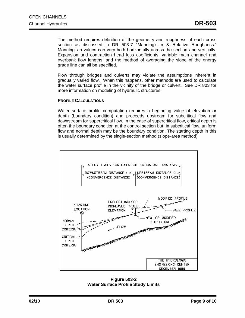
The method requires definition of the geometry and roughness of each cross section as discussed in DR 503-7 “Manning’s n & Relative Roughness.” Manning’s n values can vary both horizontally across the section and vertically. Expansion and contraction head loss coefficients, variable main channel and overbank flow lengths, and the method of averaging the slope of the energy grade line can all be specified. Flow through bridges and culverts may violate the assumptions inherent in gradually varied flow. When this happens, other methods are used to calculate the water surface profile in the vicinity of the bridge or culvert. See DR 803 for more information on modeling of hydraulic structures. PROFILE CALCULATIONS Water surface profile computation requires a beginning value of elevation or depth (boundary condition) and proceeds upstream for subcritical flow and downstream for supercritical flow. In the case of supercritical flow, critical depth is often the boundary condition at the control section but, in subcritical flow, uniform flow and normal depth may be the boundary condition. The starting depth in this is usually determined by the single-section method (slope-area method).
Figure 503-2 Water Surface Profile Study Limits

OPEN CHANNELS
Channel Hydraulics DR-503
02/10 DR 503 Page 10 of 10
Given a long enough stream reach, the water surface profile computed by step-backwater will converge to normal depth at some point upstream for subcritical flow. Establishment of the upstream and downstream boundaries of the stream reach is required to define the limits of data collection and subsequent analysis. Calculations must begin sufficiently far downstream to assure accurate results at the structure site, and continued a sufficient distance upstream to accurately determine the impact of the structure on upstream water surface profiles. This is shown in Figure 503-2.

DR-504
02/10 DR 504 Page 1 of 4
Chapter
INTRODUCTION
Subject
Purpose of the Guidance Manual
Materials Field
Sampling
Chapter
Open Channels
Subject
Channel Linings
Drainage
DR 504-1 GENERAL
Channel lining materials fall into two classes: rigid or flexible channel linings. From an erosion control standpoint, the primary difference between rigid and flexible channel linings is their response to changes in channel shape (i.e. the width, depth and alignment). Flexible linings are able to adjust to some change in channel shape while rigid linings cannot. The ability to sustain some change in channel shape improves the overall integrity of the channel lining and reduces maintenance. Flexible linings also have several other advantages compared to rigid linings. They are generally less expensive, permit infiltration and exfiltration and can be vegetated to have a natural appearance. Flexible linings are preferred over rigid linings. Rigid linings prevent infiltration but contribute to high velocities that often cause scour at the end. Despite the non-erodible nature of rigid linings, they are susceptible to failure from foundation instability. The high cost of this type of lining demands that the situation be analyzed adequately to ensure that this lining type will function as designed. The linings commonly used by KYTC are show below: Flexible Linings o Grass o Turf Reinforcing Mat o Aggregate Lining o Mattress Units (Gabions)
Rigid Linings o Concrete Paving o Grouted Riprap o Modular Block
The various types of channel linings are covered in 703 of the Standard Specifications for Road and Bridge Construction.
DR 504-2 GRASS LINING
Grass lining is one of the most common long-term channel linings. Grass lining can be accomplished either by seeding or by sodding. Seeding provides a grass

OPEN CHANNELS
Channel Linings DR-504
02/10 DR 504 Page 2 of 4
lining at a low cost but there is a transition period between seeding and vegetation establishment. Temporary protective methods such as hydroseeding or Erosion Control Blanket will hold the seeds in place. For seeded, grass lined channels Erosion Control Blanket is required to protect the seed. Erosion Control Blankets are discussed in DR-1000, “Erosion Control”. Sodding allows for an immediate application of grass lining at a higher cost than seeding. Sodding expands the use of grass lining and also serves to transition into more rigid linings. Composite linings using sodding are desirable in some applications and should be studied carefully. If sodding is able to withstand the expected flows, it is the preferred channel lining in urban applications when immediate establishment of vegetation is desired.
DR 504-3 TURF REINFORCING MAT
The concept of turf reinforcement is to provide a structure to the soil/vegetation matrix that will both assist in the establishment of vegetation and provide support to mature vegetation. To be effective, Turf Mats must be used where vegetation can establish itself. Although they are considered long term, mats do degrade over long periods of time. Turf Reinforcing Mats are preferred over aggregate lining in instances where vegetation can be established. When compared to aggregate linings, they offer similar levels of erosion protection and provide water quality benefits. Turf Reinforcing Mats are not suitable for outlet protection. When rock outlet protection is needed at the end of a culvert and has to transition into a channel lined with Turf Reinforcing Mat, specify the extension of the outlet protection for a distance of 3’ over the upstream edge of the Turf Reinforcing Mat. The bid items for turf reinforcement mats are Turf Reinforcement Mat 1, 2, 3 or 4 depending on the type used. The units of measurement for these pay items are in square yards.
DR 504-4 AGGREGATE LINING
Aggregate lining is considered a permanent lining. Three types of aggregate lining are available. Each successive class provides greater erosion prevention capability. Aggregate lining are effective solutions for cases when establishment of vegetation may become a problem.
Class II channel lining - crushed aggregate that ranges in size from five to
nine inches. Minimum thickness of lining is 15 inches. Class III channel lining - crushed aggregate that ranges in size from 0.25 to
1.5 cubic feet. Minimum thickness of lining is 24 inches. Class IV - variable size rock obtained from or near a job site with a
specified D50 and quality. Class IV rock is most commonly used as an alternate to channel lining class III.

OPEN CHANNELS
Channel Linings DR-504
02/10 DR 504 Page 3 of 4
The bid items, measurement units and D50 values for aggregate linings are shown below:
Bid Item Units D50 Channel Lining, Class II Ton 0.5’ Channel Lining, Class III Ton 1.0’ Channel Lining, Class IV Cubic Yard 1.0’
To estimate tonnage of aggregate linings, assume the unit weight is ½ ton per square yard per foot of depth (111 pounds/cubic foot). This assumes 60-70% solid density.
DR 504-5 MATTRESS UNITS
Mattress units, also called gabion baskets, consist of a wire mattress filled with crushed aggregate that ranges in size from 1.5 to 5.0 inches. Aggregate filled mattresses have a wide range of use and can offer a competitive alternate to paving on steep grades. Mattress units are bid as Channel Lining Class IA (measured in tons) in KYTC plans. Mattress units are detailed in Standard Drawing RDD 030.
DR 504-6 PAVED LINING
Paved ditch lining is placed as reinforced concrete along the bottom section of a ditch. Due to the high failure rate of paved lining channels, paved lining will be used only in extreme cases with the approval of the Division of Highway Design. Sometimes it is advantageous to pave ditches which are on very flat slopes in order to lessen sedimentation and reduce flow depth. Hydraulic analysis is necessary for this determination. Wherever paved ditches are terminated on soil, erosion is certain to occur. The erosion can be minimized by ending the ditch on as flat of a slope as possible. For instance, paved ditches should not be ended at the top of a stream bank but ended in the stream flowline. Generally, some riprap should be placed at the end of any paved ditch which ends on soil. There are two types of standardized concrete paved ditches detailed in the RDD Series of the Standard Drawings: Paved Ditch Type 1 and Paved Ditch Type 2.
DR 504-7 GROUTED & PARTIALLY GROUTED RIPRAP
Grouted riprap is a constructed by lining a channel or slope with rip rap and filling the voids with concrete or grout forming a monolithic armor. Because fully grouted riprap is a rigid structure, it will not conform to settlement or toe undermining as loose riprap does. Therefore, fully grouted riprap is susceptible to mass failure, especially if pore water is not allowed to drain properly. Although the revetment is rigid, it is not particularly strong and even a small loss of toe or bank support can result in the failure of large portions of the structure.

OPEN CHANNELS
Channel Linings DR-504
02/10 DR 504 Page 4 of 4
An alternative to fully grouted riprap is partially grouted riprap. In general, the objective is to increase the stability of the riprap without sacrificing its flexibility. Partial grouting of riprap may be well suited for areas where rock of sufficient size is not available to construct a loose riprap revetment. When used on a project, bid items to pay for the construction of grouted and partially grouted rip rap should include Concrete Class B and Channel Lining.

DR-505
02/10 DR 505 Page 1 of 5
Chapter
INTRODUCTION
Subject
Purpose of the Guidance Manual
Materials Field
Sampling
Chapter
Open Channels
Subject
Channel Lining Hydraulics
Drainage
DR 505-1 APPLIED SHEAR STRESS
The hydrodynamic force of water flowing in a channel is known as the tractive force. The basis for stable channel design with flexible lining materials is that flow-induced tractive force applied by the force of the water should not exceed the permissible or critical shear stress of the lining materials. This flow induced force, or shear stress, is given as:
Equation 505-1 Applied Shear Stress
d = 62.4 d So
Where: d = shear stress in channel at maximum depth, lb/ft2
d = maximum depth of flow in the channel for the design discharge, ft So =average bottom slope, ft/ft
DR 505-2 MANNING’S ROUGHNESS
As noted in DR 503-7, in situations where the relative roughness is large (shallow depth over rough surfaces), the Manning’s roughness coefficient varies with depth. When analyzing flexible linings this variance is accounted for. When using manning’s equation to solve for depth for lined channels the following guidance should be used. Table 505-1 gives manning’s roughness coefficients for several different lining types. Notably absent from this table is Manning’s roughness values for grass linings. The method to determine Manning’s n for grass linings is discussed below.
GRASS LINING
Manning's roughness coefficient for vegetated linings varies significantly depending on the amount of submergence of the vegetation (depth) and the flow force exerted on the channel bed. As a result, the Manning's n value must be determined by trial and error taking into consideration both the depth of flow and the flow force. The Soil Conservation Service (now known as the Natrual Resources Conservation Service) developed a classification of vegetation depending on the

OPEN CHANNELS
Channel Lining Hydraulics DR-505
02/10 DR 505 Page 2 of 5
TABLE 505-1 MANNING’S ROUGHNESS COEFFICIENTS
Category Type Depth Ranges
0 - 0.5 ft 0.5 – 2.0 ft > 2.0 ft
Rigid Concrete 0.015 0.013 0.013
Grouted Riprap 0.040 0.030 0.028
Stone Masonry 0.042 0.032 0.030
Soil Cement 0.025 0.022 0.020
Asphalt 0.018 0.016 0.016
Unlined Bare Soil 0.023 0.020 0.020
Rock Cut 0.045 0.035 0.025
Temp. Woven Paper * 0.016 0.015 0.015
Jute Net 0.028 0.022 0.019
Fiberglass Roving 0.028 0.022 0.019
Straw w/ Net 0.065 0.033 0.025
Curled Wood Mat 0.066 0.035 0.028
Synthetic Mat 0.036 0.025 0.021
Gravel: 1-inch D50
2-inch D50 0.044 0.066
0.033 0.041
0.030 0.034
Riprap: 6-inch D50 (Class II) 12-inch D50 (Class III & IV)
0.104 ---
0.069 0.078
0.035 0.040
Table 505-2 CLASSES OF VEGETAL COVERS AND DEGREES OF RETARDANCE
Retardance Class
Cover
Condition
A
Weeping Lovegrass Good stand, tall (ave. 30”), Excellent
Yellow Bluestem Ischaemum Good stand, tall (ave. 36”), Excellent
B
Kudzu Very dense growth, uncut
Bermuda grass Good stand, tall (ave. 12”)
Native grass mixture – little bluestem, blue gamma other short and long stem midwest grasses
Good stand, unmowed
Weeping lovegrass Good stand, tall (ave. 2.0’)
Laspedeza sericea Good stand, not woody, tall (ave. 2.0')
Alfalfa Good stand, uncut (ave. 1.0')
Weeping lovegrass Good stand, uncut (ave. 1.0')
Kudzu Dense growth uncut
Blue gamma Good stand, uncut (ave. 1.0')
C
Crabgrass Fair stand, uncut (10”- 48”)
Bermuda grass Good stand, Mowed (ave. 6”)
Common lespedeza Good stand, uncut (ave. 12”)
Grass-legume mixture: Orchard grass redtop, Italian ryegrass, and common lespedeza
Good stand, summer uncut (6”-8”)
Centipedegrass Very dense cover (ave. 6”)
Kentucky bluegrass Good stand, (6” - 12”)

OPEN CHANNELS
Channel Lining Hydraulics DR-505
02/10 DR 505 Page 3 of 5
Table 505-2 CLASSES OF VEGETAL COVERS AND DEGREES OF RETARDANCE
Retardance Class
Cover
Condition
D
Bermuda grass Good stand, cut to 2.5”
Common lespedeza Excellent stand, uncut (ave. 4.5”)
Buffalo grass
Grass-legume mixture: fall, spring (orchard grass, redtop)
Good stand, uncut (4” – 5”)
Italian ryegrass, and common lespedeza
Lespedeza sericea After cutting to 2” (very good before cutting)
E Bermuda grass Good stand, cut to 1.5”
Bermuda grass Burned stubble
Table 505-3 Manning’s Roughness Coefficient for Classes of Vegetal Covers
Retardance Class Manning's n Equation*
A n = K R1/6 / [K2 + 19.97 log (R1.4 So 0.4)] K = 1.22 (1.0 English) K2 = 30.2 (15.8 English)
B n = K R1/6 / [K2 + 19.97 log (R1.4 So 0.4)] K = 1.22 (1.0 English) K2 = 37.4 (23.0 English)
C n = K R1/6 / [K2+ 19.97 log (R1.4 So 0.4)] K = 1.22 (1.0 English) K2 = 44.6 (30.2 English)
D n = K R1/6 / [K2+ 19.97 log (R1.4 So 0.4)] K = 1.22 (1.0 English) K2 = 49.0 (34.6 English)
E n = R1/6 / K2+ 19.97 log (R1.4 So 0.4)] K = 1.22 (1.0 English) K2 = 52.1 (37.7 English)
*Equations are valid for flows less than 1.42 m3/s (50 ft3/s). R = Hydraulic Radius
degree of retardance. Grasses are classified into five broad categories, as shown in Table 505-2. Retardance Class A presents the highest resistance to flow and Class E presents the lowest resistance to flow. In general, taller and stiffer grass species have a higher resistance to flow (higher manning’s n), while short flexible grasses have a low-flow resistance (low manning’s n). Table 505-3 gives the relationships used to determine manning’s n for the various vegetation classes. Exhibits 500-1 and 500-2 show this relationship plotted for class C and D vegetation. It is KYTC practice to assume vegetation Class C for all grass lined channels.

OPEN CHANNELS
Channel Lining Hydraulics DR-505
02/10 DR 505 Page 4 of 5
TURF REINFORCING MAT
The stability analysis for Turf Reinforcing Mats assumes the mats have established vegetation. This analysis is based on the long term performance of the mat over its service life. There will be a period when first installed that the turf mat can be exposed to flows before the vegetation is established. Any analysis of the short term stability would be based on a much smaller return interval that the normal 10 year design storm. Since turf mats provide a much higher degree of erosion resistance than bare soil, it is assumed that the risks of short term failure are small if the channels long term stability is suitable. Therefore short term analysis is not required. In light of this, Manning’s roughness coefficients are determined as specified for grass linings in Section 505-2 above. AGGREGATE LINING
Much research has been performed to determine the roughness of aggregate channel lining. As with vegetation, the manning’s roughness for aggregate linings can vary significantly with depth. Flow over aggregate lined channels is complicated due to the fact the ratio of the roughness height to the channel depth is much higher than other drainage materials. This causes high relative roughness values and the individual rock fragments to protrude into the flow. While the values from Table 505-1 can be used for aggregate linings, alternate procedures as described in HEC-15 and the Hydrain HYCHL documentation are also acceptable.
MATTRESS UNITS
Roughness characteristics of gabion mattresses are governed by the size of the rock in the baskets and the wire mesh enclosing the rock. For practical purposes, the effect of the mesh can be neglected. Therefore, Manning’s roughness should be determined using the D50 of the basket rock as applied to the relationships provided for riprap and gravel linings. For KYTC units use the values given for 2 inch gravel in Table 505-1.
DR 505-3 PERMISSIBLE SHEAR STRESS
Permissible shear stress, d, indicates the stress that a lining material can
withstand before erosion of the lining will occur. For a channel lining to be stable, the permissible shear stress must be less than the applied shear stress calculated in equation 505-1. Permissible shear stress of the most common KYTC linings is given in Table 505-2 below. A more extensive listing of permissible shear stress values is given in Exhibit 500-3.

OPEN CHANNELS
Channel Lining Hydraulics DR-505
02/10 DR 505 Page 5 of 5
Table 505-4 Permissible Shear Stress For Flexible Linings
Lining Permissible Shear Stress, lb/ft2 1Grass Lining (Seed or Sod) 1.0 2Turf Reinforcing Mat Type 1 6.0 2Turf Reinforcing Mat Type 2 8.0 2Turf Reinforcing Mat Type 3 10.0 2Turf Reinforcing Mat Type 4 12.0
3Channel Lining Class II 2.5 3Channel Lining Class III 5.0 3Channel Lining Class IV 5.0
3Channel Lining Class IA (Mattress Units) 35.0
1. Assuming class C vegetation 2. Assuming vegetated conditions. 3. Alternate methods as described in HEC-15 and Hydrain HYCHL
documentation are also acceptable.

DR-506
02/10 DR 506 Page 1 of 3
Chapter
INTRODUCTION
Subject
Purpose of the Guidance Manual
Materials Field
Sampling
Chapter
Open Channels
Subject
Stream Channel Considerations
Drainage
DR 506-1 GENERAL
Stream channels as classified in KYTC policy are essentially natural channels. Stream channels often involve complex rapidly changing flow conditions and are environmentally sensitive to changes. Stream channels often drainage large areas and carry significant amounts of runoff. Because of this, modifications to stream channels require environmental and hydraulic considerations beyond that required for uniform roadside ditches.
DR 506-2 NATURAL STREAM TYPES
Natural streams are classified into 3 different types. Although there are numerous definitions of these steam types, it is widely accepted that the 3 basic types of natural streams are Ephemeral, Intermittent, and Perennial. The United States Army Corps of Engineers (USACE) defines these streams as follows:
Ephemeral stream: An ephemeral stream has flowing water only during, and for a short duration after, precipitation events in a typical year. Ephemeral stream beds are located above the water table year-round. Groundwater is not a source of water for the stream. Runoff from rainfall is the primary source of water for stream flow.
Intermittent stream: An intermittent stream has flowing water during certain times of the year, when groundwater provides water for stream flow. During dry periods, intermittent streams may not have flowing water. Runoff from rainfall is a supplemental source of water for stream flow.
Perennial stream: A perennial stream has flowing water year-round during a typical year. The water table is located above the stream bed for most of the year. Groundwater is the primary source of water for stream flow. Runoff from rainfall is a supplemental source of water for stream flow.
Another common term used to describe steams is “blue line streams”. United States Geological Survey (USGS) maps show Intermittent and Perennial streams as blue lines, hence the term “blue line stream”. It should be noted that the determination of stream types as shown on USGS maps follows the USGS definition, which is different than the USACE definition presented above.

OPEN CHANNELS
Stream Channel Considerations DR-506
02/10 DR 506 Page 2 of 3
DR 506-3 QUANTIFYING STREAM IMPACTS
In order to quantify the impacts to streams it is necessary to determine the horizontal limits of what is considered to be a part of the stream. The methods to determine of the limits of a stream vary significantly. In most instances this limit is bounded by the ordinary high water mark. The USACE defines the ordinary high water mark as; “that line on the shore established by the fluctuations of water and indicated by physical characteristics such as clear, natural line impressed on the bank, shelving, changes in the character of soil, destruction of terrestrial vegetation, the presence of litter and debris, or other appropriate means that consider the characteristics of the surrounding areas.” In cases where the ordinary high water marks cannot be defined, the limits of the 2 year storm can be used to estimate the ordinary high water mark. Once there is a determination made of the limits of a stream, stream impacts are either measured linearly, or by the amount of area of stream disturbed. In the linear case, the impact is simply measured as the length of disturbance below the ordinary high water mark as measured along the stream. In the area case, it is measured as the area of stream impacted (as defined by the limits described above).
DR 506-4 STREAM IMPACT THRESHOLDS
As noted in DR 502-1, stream channels include any drainage feature that is currently or has ever been a natural drainage feature. This definition is inclusive of all three types of steams discussed in DR 506-2. Impacts to any stream channels that exceed certain thresholds require coordination with other state and federal agencies. Since these thresholds vary significantly between the various state and federal agencies, the determination of these impacts is left to the Division of Environmental Analysis. Although some environmental agencies do not extend their jurisdiction to include ephemeral streams, this determination should be made by the Division of Environmental Analysis. Projects that have stream impacts to stream channels exceeding the following thresholds shall be coordinated with the Division of Environmental Analysis: Disturbances to stream channels that exceed 300 linear feet Disturbances to stream channels that result in a loss of waters of more
that 0.1 acres DR 506-5 CHANNEL CHANGES
When a stream channel is reconstructed, and the reconstruction exceeds the impact thresholds in DR 506-4, it is referred to as a channel change. The possibility of any Channel Change should be identified in the Conceptual Design phase when the preliminary line and grade plans are developed. Reconstruction or impacts to streams that fall below the aforementioned thresholds are treated

OPEN CHANNELS
Stream Channel Considerations DR-506
02/10 DR 506 Page 3 of 3
as roadside ditches and should be designed as such.
DR 506-6 WETLAND IMPACTS
Identifying the extent of wetlands is a complicated process that is not covered in this manual. It is imperative to determine the location of any wetland impacts early in the project’s design phase. Any possible impact to a wetland must be coordinated through the Division of Environmental Analysis. More information on wetlands can be found in Sections HD 400 and HD 500 of the Highway Design Manual
DR 506-7 AVOIDANCE OF STREAM & WETLAND IMPACTS
By far the most effective way to deal with steam and wetland impacts is to avoid them altogether. Avoidance of these impacts is desired from both an environmental and fiscal standpoint. As of the writing of this section of the Drainage manual, the mitigation costs of impacts to streams and wetlands were estimated to be:
$72,000 per acre for wetlands
$120 - $320 per linear foot for stream impacts DR 506-8 PERMITTING AND OTHER ENVIRONMENT CONSIDERATIONS
There are many permitting and environmental considerations that should be considered when dealing with impacts to stream channels. Most of these considerations are related to hydraulic structures such as culverts or bridges. However, any work that creates a disturbance to a stream channel, should account for environmental and permitting considerations. For more information please see Sections DR 802 and DR 601-3 of the Drainage Manual and HD 400 and HD 500 of the Highway Design Manual.

DR-507
02/10 DR 507 Page 1 of 10
Chapter
INTRODUCTION
Subject
Purpose of the Guidance Manual
Materials Field
Sampling
Chapter
Open Channels
Subject
Stream Stability
Drainage
DR 507-1 GENERAL
The form assumed by a natural stream, which includes its cross-sectional shape and its planform, is a function of many variables for which cause-and-effect relationships are difficult to establish. The natural stream channel will assume a geomorphological form that will be compatible with the sediment load and discharge history, which it has experienced over time. Both natural and manmade causes can create instability, thus changing this form. An understanding of stream stability is essential to:
locating hydraulic stream crossings Identify potential problems with the stability of a proposed highway
crossing Stream stability issues are primarily of concern in the location and design of large hydraulic crossings such as bridge or culverts. However, there are instances where stream stability is concern when crossings are not involved. A prime example of this is when roads are constructed next to streams. Observation is the best means of identifying potential locations for stream stability issues.
The discussion that follows is only a brief introduction of stream stability. The Federal Highway Administration (FHWA) has published a series of 3 Hydraulic Engineering Circulars (HEC) that deal with steam stability and bridge scour. Figure 507-1 shows the interrelationship of these documents and the topics covered in them. HEC 20 “Stream Stability at Highway Structures” (2001) is the primary reference on stream stability. The primary stream stability issues that could have an effect on a proposed highway stream crossing project include: Stream Stability (Discussed Here)
o Planform changes o Channel cross section changes

OPEN CHANNELS
Stream Stability DR-507
02/10 DR 507 Page 2 of 10
Figure 507-1 Hydraulic Engineering Circulars on Stream Morphology & Bridge Scour

OPEN CHANNELS
Stream Stability DR-507
02/10 DR 507 Page 3 of 10
Planform changes involve the relocation of the streams lateral position. Meander migration is an example of a planform change. Channel cross section changes include the natural widening or narrowing of a stream. Planform and cross sectional changes are the primary concern in stream stability analysis as discussed in this chapter and HEC 20. Scour, including long term aggregation and degradation are discussed in chapter DR 800. HISTORIC AERIAL PHOTOGRAPHY When available, a time series of historic aerial photographs of a stream site is an effective method to determine if stream stability issues are present. It can be readily determined if a stream has exhibited movement by overlaying these photographs on each other and comparing the relative positions of the stream over time. The Division of Graphic Design and Printing at KYTC has an extensive collection of aerial photography dating back to the 1960’s in some locations. Other sources for such photography include the United States Geological Survey, United States Department of Agriculture and many other private companies that offer subscription type services.
DR 507-2 LEVELS OF ASSESSMENT
The analysis and design of a stream channel will usually require an assessment of the existing channel and the potential for problems as a result of a proposed impact to the stream. The detail of studies necessary should be commensurate with the risk associated with the action and with the environmental sensitivity of the stream. Analytical methods for the evaluation of channel stability can be classified as either hydraulic or geomorphic, and it is important to recognize that these analytical tools should only be used to substantiate the erosion potential indicated through observation. If it is determined through observation that a stream stability assessment is needed for a project, it is recommended to follow the “levels of assessment” procedure indicated in HEC-20. The end result of each level of assessment is a determination of the need to proceed to the next level of assessment. Flowcharts mapping each level of analysis can be found in HEC 20. Brief descriptions of the three levels of assessment are as follows.
Level 1 Qualitative assessment involving the application of geomorphic concepts to identify potential problems and alternative solutions. Data needed may include historic information, current site conditions, aerial photographs, old maps and survey notes, bridge design files, maintenance records, and interviews with long-time residents.

OPEN CHANNELS
Stream Stability DR-507
02/10 DR 507 Page 4 of 10
Level 2 Quantitative analysis combined with a more detailed qualitative assessment of geomorphic factors. Generally includes water surface profile and scour calculations. This level of analysis will be adequate for most locations if the problems are resolved and relationships between different factors affecting stability are adequately explained. Data needed will include Level 1 data in addition to the information needed to establish the hydrology and hydraulics of the stream. Level 3 Complex quantitative analysis based on detailed mathematical modeling and possibly physical hydraulic modeling. Necessary only for high-risk locations, extraordinarily complex problems and possibly after-the-fact analysis where losses and liability costs are high. This level of analysis may require professionals experienced with mathematical modeling techniques for sediment routing and/or physical modeling. Data needed will require Level 1 and 2 data and field data on bed load and suspended load transport rates and properties of bed and bank materials (e.g., size, shape, gradation, fall velocity, cohesion, density, angle of repose).
The level of assessment concept is similar to the risk assessment used in the analysis of bridge crossings. However, it should be noted that these are two different procedures. The levels of assessment described here pertain only stream stability issues, whereas the Risk Assessment discussed in DR 807 applies primarily to bridge hydraulics.
DR 507-3 FACTORS THAT AFFECT STREAM STABILITY
Factors that affect stream stability and, potentially, bridge and highway stability at stream crossings, can be classified as geomorphic factors and hydraulic factors. Geomorphic Factors Include:
stream size
valley setting
natural levees
sinuosity
width variability
bar development
flow variability
floodplains
apparent incision
channel boundaries
degree of braiding
degree of anabranching
Figure 507-2 pictorially shows these geomorphic factors. Each of these factors is discussed individually in HEC 20. Hydraulic Factors Include:
magnitude, frequency and duration of floods

OPEN CHANNELS
Stream Stability DR-507
02/10 DR 507 Page 5 of 10
bed configuration
resistance to flow
water surface profiles
Figure 507-3 depicts the changes in channel classification and relative stability as related to hydraulic factors. Rapid and unexpected changes may occur in streams in response to man’s activities in the watershed such as alteration of vegetative cover. Changes in perviousness can alter the hydrology of a stream, sediment yield and channel geometry. Channelization, stream channel straightening, stream levees and dikes, bridges and culverts, reservoirs, and changes in land use can have major effects on stream flow, sediment transport, and channel geometry and location. Knowing that man’s activities can influence stream stability can help the designer anticipate some of the problems that can occur. Natural disturbances (e.g., floods, drought, earthquakes, landslides, volcanoes, forest fires) can also cause large changes in sediment load and thus major changes in the stream channel. Although difficult to plan for such disturbances, it is important to recognize that, when natural disturbances do occur, it is likely that changes will also occur to the stream channel.
DR 507-4 AGGRADATION / DEGRADATION
Aggradation and degradation are the vertical raising and lowering, respectively, of the streambed over relatively long distances and time frames. Such changes can be the result of both natural and man-induced changes in the watershed. The sediment continuity concept is the primary principle applied in both qualitative and quantitative analyses of bed elevation changes.

OPEN CHANNELS
Stream Stability DR-507
02/10 DR 507 Page 6 of 10
Figure 507-2 Geomorphic Factors That Affect Stream Stability

OPEN CHANNELS
Stream Stability DR-507
02/10 DR 507 Page 7 of 10
FIGURE 507-3
CHANNEL CLASSIFICATION AND RELATIVE STABILITY AS HYDRAULIC FACTORS ARE VARIED
DR 507-5 STREAM RESPONSE TO CHANGE
The major complicating factors in river mechanics are 1) the large number of interrelated variables that can simultaneously respond to natural or imposed changes in a stream system; and 2) the continual evolution of stream channel patterns, channel geometry, bars and forms of bed roughness with changing water and sediment discharge. To better understand the responses of a stream to the actions of man and nature, a few simple hydraulic and geomorphic concepts are presented herein. The dependence of stream form on slope, which may be imposed independently of other stream characteristics, is illustrated schematically in Figure 507-4. Any natural or artificial change that alters channel slope can result in modifications to the existing stream pattern. For example, a cutoff of a meander loop decreases channel sinuosity and increases channel slope. Referring to Figure 507-4, this shift in the plotting position to the right could result in a shift from a relatively tranquil, meandering pattern toward a braided pattern that varies rapidly with time, has high velocities, is subdivided by sandbars and carries relatively large quantities of sediment. Conversely, it is possible that a slight decrease in slope could change an unstable braided stream into a meandering one.

OPEN CHANNELS
Stream Stability DR-507
02/10 DR 507 Page 8 of 10
FIGURE 507-4 SINUOSITY VERSUS SLOPE WITH CONSTANT DISCHARGE
The different channel dimensions, shapes and patterns associated with different quantities of discharge and amounts of sediment load indicate that, as these independent variables change, major adjustments of channel morphology can be anticipated. Further, a change in hydrology may cause changes in stream sinuosity, meander wave length, and channel width and depth. A long period of channel instability with considerable bank erosion and lateral shifting of the channel may be required for the stream to compensate for the hydrologic change. Figure 507-5 illustrates the dependence of river form on channel slope and discharge, showing when SQ0.25 < 0.00070 in a sandbed channel, the stream will meander. Similarly, when SQ0.25 ≥ 0.0041, the stream is braided. In these equations, S is the channel slope in feet per foot, and Q is the mean discharge in cubic feet per second. Between these values of SQ0.25 is the transitional range. Many rivers the U.S. are classified as intermediate sand-bed streams and plot in this zone between the limiting curves defining meandering and braided streams. If a stream is meandering but its discharge and slope border on a boundary of the transitional zone, a relatively small increase in channel slope may cause it to change, in time, to a transitional or braided stream.

OPEN CHANNELS
Stream Stability DR-507
02/10 DR 507 Page 9 of 10
1.E-05
1.E-04
1.E-03
1.E-02
1.E-01
1.E+02 1.E+03 1.E+04 1.E+05 1.E+06
Discharge (cfs)
Slope
(ft/ft)
Braided
Transitional
Meandering
Figure 507-5 Slope-Discharge for Braiding or Meandering Bed Streams
DR 507-6 STREAM STABILITY COUNTERMEASURES
A countermeasure is defined as a measure incorporated into a highway crossing of a stream to control, inhibit, change, delay or minimize stream and bridge-stability problems. They may be installed at the time of highway construction or retrofitted to resolve stability problems at existing crossings. Retrofitting is good economics and good engineering practice in many locations because the magnitude, location and nature of potential stability problems are not always discernible at the design stage and, indeed, may take a period of several years to develop. The selection of an appropriate countermeasure for a specific bank erosion problem is dependent on factors such as the erosion mechanism, stream characteristics, construction and maintenance requirements, potential for vandalism and costs. Below is a brief discussion of possible countermeasures for some common river-stability problems; meander migration, channel braiding, degredation and aggredation. MEANDER MIGRATION
SQ 0.25 = 0.010
SQ 0.44 = 0.080
SQ 0.25 = 0.0017

OPEN CHANNELS
Stream Stability DR-507
02/10 DR 507 Page 10 of 10
The best countermeasure against meander migration is a crossing location on a relatively straight reach of stream between bends. Other countermeasures include the protection of an existing bank line, the establishment of a new flow line or alignment and the control and constriction of channel flow. Countermeasures identified for bank stabilization and bend control are bank revetments, spurs, retardance structures, longitudinal dikes, vane dikes, bulkheads, and channel relocations. Measures may be used individually or a combination of two or more measures may be used to combat meander migration at a site. CHANNEL BRAIDING
Countermeasures used at braided streams are usually intended to confine the multiple channels to one channel. This tends to increase sediment transport capacity in the principal channel and encourage deposition in secondary channels. The measures usually consist of dikes constructed from the limits of the multiple channels to the channel over which the bridge is constructed. Spur dikes at bridge ends used in combination with revetment on highway fill slopes, riprap on highway fill slopes only and spurs arranged in the stream channels to constrict flow to one channel have also been used successfully. DEGRADATION
Degradation in streams can cause the loss of bridge piers in stream channels and piers and abutments in caving banks. A check dam, which is a low dam or weir constructed across a channel, is one of the most successful techniques for halting degradation on small to medium streams. Longitudinal stone dikes placed at the toe of channel banks can be effective countermeasures for bank caving in degrading streams. Precautions to prevent outflanking (e.g., tiebacks to the banks) may be necessary where installations are limited to the vicinity of the highway stream crossing. In general, channel lining alone is not a successful countermeasure against degradation problems. AGGRADATION
Current measures in use to alleviate aggradation problems at highways include channelization, bridge modification, continued maintenance or combinations of these. Channelization may include excavating and cleaning channels, constructing cutoffs to increase the local slope, constructing flow-control structures to reduce and control the local channel width, and constructing relief channels to improve flow capacity at the crossing. Except for relief channels, these measures are intended to increase the sediment transport capacity of the channel, thus reducing or eliminating problems with aggradation.

DR-508
02/10 DR 508 Page 1 of 6
Article I.
Section 1.01
Section 1.02 Chapter
INTRODUCTION
Section 1.03
Section 1.04 Subject
Purpose of the Guidance Manual
Materials Field
Sampling
Open Channels
Channel Design Procedures
Drainage
DR 508-1 ROADSIDE DITCHES
The alignment, cross section and grade of roadside channels is usually constrained to a large extent by the geometric and safety standards applicable to the project. These channels should accommodate the design runoff to ensure the safety of motorists and to minimize future maintenance, damage to adjacent properties and adverse environmental or aesthetic effects. Each project is unique, but the following six basic design steps are normally applicable:
Step 1 Assemble Site Data and Project File
A) Collect available site data.
B) Obtain or prepare existing and proposed plan-profile layout including highway, culverts and bridges.
C) Determine and plot on the plan the locations of natural basin divides and roadside channel outlets. An example of a roadside channel plan/profile is shown in Figure 508-1.
D) Perform the layout of the proposed roadside channels to minimize diversion flow lengths.
Step 2 Obtain or Establish Cross Section Data
A) Provide channel depth adequate to drain the subbase and minimize freeze-thaw effects
B) Choose channel side slopes based on geometric design criteria
including safety, economics, soil, aesthetics, access and recommendations in the geotechnical reports.
C) Establish bottom width of trapezoidal channel
D) Identify features that may restrict cross section design

OPEN CHANNELS
Channel Design Proedures DR-508
02/10 DR 508 Page 2 of 6
right-of-way limits
trees or environmentally sensitive areas
utilities, and
existing drainage facilities
710
700
Dra
inag
e
Div
ide
Berm
Crest
Dra
inag
e
Div
ide
Dra
inag
e
Div
ide
DBI
10 15 20
Figure 508-1 Roadside Channel Plan & Profile
Step 3 Determine Initial Channel Grades
A) Plot initial grades on plan-profile layout. (Slopes in roadside ditch in cuts are usually controlled by highway grades)
B) Provide minimum grade of 0.3% to minimize ponding and
sediment accumulation C) Consider influence of type of lining on grade D) Where possible, avoid features that may influence or restrict grade
(e.g., utility locations)
Step 4 Check Flow Capacities and Adjust as Necessary
A) Compute the design discharge at the downstream end of a channel segment (see Hydrology Chapter)
B) Set preliminary values of channel size, roughness coefficient and
slope C) Determine maximum allowable depth of channel including

OPEN CHANNELS
Channel Design Proedures DR-508
02/10 DR 508 Page 3 of 6
freeboard D) Check flow capacity using Manning’s equation and single-section
analysis E) If capacity is inadequate, possible adjustments are as follows:
increase bottom width
make channel side slopes flatter
make channel slope steeper
provide smoother channel lining
install drop inlets and a parallel storm drain pipe beneath the channel to supplement channel capacity
F) Provide smooth transitions at changes in channel cross sections
G) Provide extra channel storage where needed to replace floodplain
storage and/or to reduce peak discharge
Step 5 Determine Channel Lining/Protection Needed (DR 504 & DR 505)
A) Select a lining and determine the permissible shear stress p in lb/ft2. See DR 505-3 “Permissible Shear Stress.”
B) Estimate the flow depth and choose an initial Manning’s n value.
See DR 505-2 “Manning’s Roughness.”
C) Calculate normal flow depth, yo (ft), at design discharge using Manning’s equation and compare with the estimated depth. If they do not agree, repeat Steps 5B and 5C.
D) Compute maximum shear stress at normal depth as:
d (lb/ft2) = 62.4 yoS, where S = channel slope, ft/ft
E) If d < p, then lining is acceptable. Otherwise consider the following options:
choose a more resistant lining;
use concrete, gabions or other more rigid lining either as full lining or composite
decrease channel slope
decrease slope in combination with drop structures
increase channel width and/or flatten side slopes
Step 6 Analyze Outlet Points and Downstream Effects
A) Identify any adverse impacts (e.g., increased flooding or erosion to downstream properties) that may result from one of the following at the channel outlet

OPEN CHANNELS
Channel Design Proedures DR-508
02/10 DR 508 Page 4 of 6
increase or decrease in discharge
increase in velocity of flow
concentration of sheet flow
change in outlet water quality
diversion of flow from another watershed
B) Mitigate any adverse impacts identified in Step 6A. Possibilities include:
enlarge outlet channel and/or install control structures to provide detention of increased runoff in channel
install velocity-control structures (energy dissipators),
increase capacity and/or improve lining of downstream channel,
install sedimentation/infiltration basins,
install sophisticated weirs or other outlet devices to redistribute concentrated channel flow, and
eliminate diversions that result in downstream damage and that cannot be mitigated in a less expensive fashion.
DR 508-2 STREAM CHANNELS
The analysis of a stream channel in most cases is in conjunction with the design of a highway hydraulic structure such as a culvert or bridge. In general, the objective is to convey the water along or under the highway such that it will not cause damage to the highway, stream or adjacent property. An assessment of the existing channel is usually necessary to determine the potential for problems that might result from a proposed action. The detail of studies necessary should be commensurate with the risk associated with the action and with the environmental sensitivity of the stream and adjoining floodplain. Although the following step-by-step procedure may not be appropriate for all possible applications, it does outline a process that will usually apply.
Step 1 Assemble Site Data and Project File
A) Data Collection
Topographic, site, and location maps
Roadway profile
Photographs
Field review
Design data at nearby structures
Gaging records
Historic flood data and local knowledge
B) Studies by other agencies
Flood insurance studies

OPEN CHANNELS
Channel Design Proedures DR-508
02/10 DR 508 Page 5 of 6
Floodplain studies
Watershed studies
C) Environmental constraints
Floodplain encroachment
Floodway designation
Fish and wildlife habitat
Commitments in review documents
D) Determine design criteria
Step 2 Determine the Project Scope
A) Determine potential stream impacts (See DR 506).
B) Determine level of assessment
Stability of existing channel
Potential for damage
Sensitivity of the stream
C) Determine type of hydraulic analysis
Qualitative assessment
Single-section analysis
Step-backwater analysis
Special analysis techniques
D) Determine additional survey information
Extent of streambed profiles.
Locations of cross sections.
Extent of cross section survey lines.
Elevations of flood-prone property.
Details of existing structures.
Properties of bed and bank materials
Step 3 Evaluate Hydrologic Variables and Compute Discharges for Selected Frequencies
Step 4 Determine Appropriate Analysis Technique and Perform Hydraulic
Analysis
A) Single-section analysis
Select representative cross section
Select appropriate n values.
Compute stage-discharge relationship

OPEN CHANNELS
Channel Design Proedures DR-508
02/10 DR 508 Page 6 of 6
B) Step-backwater analysis. C) Special analysis techniques D) Calibrate with known highwater
Step 5 Perform Stability Analysis
A) Geomorphic factors B) Hydraulic factors C) Stream response to change
Step 6 Design Countermeasures
A) Criteria for selection
Erosion mechanism
Stream characteristics
Construction and maintenance requirements
Vandalism considerations
Cost
B) Types of countermeasures
Meander migration countermeasures
Bank stabilization
Bend control countermeasures.
Channel braiding countermeasures
Degradation countermeasures
Aggradation countermeasures
C) For additional information
HEC 20 Stream Stability at Highway Structures
HEC-18 Evaluating Scour at Bridges
HEC-23 Bridge Scour and Stream Instability Countermeasures
HDS No. 6 River Engineering for Highway Encroachments
Step 7 Documentation (See DR 300)

DR-509
02/10 DR 509 Page 1 of 1
Chapter
INTRODUCTION
Subject
Purpose of the Guidance Manual
Materials Field
Sampling
Chapter
Open Channels
Subject
Channel Design Criteria Summary
Drainage
DR 509-1 ROADSIDE DITCHES
The following criteria apply to roadside channels: Design channel geometry that addresses the considerations presented in
DR 502-3 “Roadside Ditch Geometry Considerations.” Design channel linings in accordance with the method of allowable
tractive force specified in DR 505 The design discharge for permanent ditches shall use a 10 year storm for
capacity and lining design Provide a freeboard of 1’ between the 10 year water surface elevation
and the shoulder elevation
Documentation of drainage calculations in Drainage Folders is only required for ditches that exceed the following criteria:
For Channel slopes < 1.0%, provide calculations for channels that drain more than 2 acres.
For Channel slopes < 2.0% and >1.0% provide calculations for channels that drain more than ½ acres.
Provide calculations for all channels with slopes exceeding 2.0%.
DR 509-2 STREAM CHANNELS
Where possible avoid impacts to steam channels. When stream impacts exceed thresholds described in DR 506, coordinate with the Division of Environmental Analysis. Treat design of stream channels that do not exceed the aforementioned thresholds as roadside ditches and follow criteria listed above.

EXHIBIT
Manning’s n for Vegetation Class C DR 500-1
02/10 DR 500-1 Page 1 of 1
0.1
1
10
0.0100.1001.000
n
R
0.001 0.003 0.005 0.01 0.03 0.05 0.1
0.010
0.005
0.003
0.030
0.050
0.100
Channel Slope
n = R1/6
30.2 + 19.97 log ( R1.4
S0.4
)
0.001

EXHIBIT
Manning’s n for Vegetation Class D DR 500-2
02/10 DR 500-2 Page 1 of 1
0.1
1
10
0.0100.1001.000
n
R
0.001 0.003 0.005 0.01 0.03 0.05 0.1
0.010
0.005
0.003
0.030
0.050
0.100
Channel Slope
n = R1/6
34.6 + 19.97 log ( R1.4
S0.4
)
0.001

EXHIBIT
Permissible Shear Stresses DR 500-3
02/10 DR 500-3 Page 1 of 1
SUMMARY OF SHEAR STRESS FOR VARIOUS LINERS
Protective Cover
Underlying Soil
(psf)
Class A Vegetation Erodible or Erosion Resistant 3.7
Class B Vegetation Erodible or Erosion Resistant 2.1
Class C Vegetation Erodible or Erosion Resistant 1.0
Class D Vegetation Erodible or Erosion Resistant 0.60
Class E Vegetation Erodible or Erosion Resistant 0.35
Bare Soil (Refer to Table 5-4 and Table 5-5)
Hydroseeded 0.10
Woven Paper 0.15
Jute Net 0.45
Single Fiberglass 0.60
Double Fiberglass 0.85
Straw W/Net 1.45
Curled Wood Mat 1.55
Synthetic Mat 2.00
Plain Grass, Good Cover Clay N/A
Plain Grass, Average Cover Clay N/A
Plain Grass, Poor Cover Clay N/A
Grass, Reinforced W/Nylon Clay N/A
Dycel W/Grass Clay N/A
Petraflex W/Grass Clay N/A
Armorflex W/Grass Clay N/A
Dymex W/Grass Clay N/A
Grasscrete Clay N/A
Gravel: D50 = 1 in D50 = 2 in
0.40 0.80
Rock: D50 = 6 in D50 = 12 in
2.50 5.00
Gabions (6 in) Geoweb (4 in)
Type I Type I
35 10
Soil Cement (8% Cement) Type I >45
Dycel W/O Grass Type I >7.0
Petraflex W/O Grass Type I >32
Armorflex W/O Grass Type I 12-20
Erikamat w/3 in Asphalt Type I 13-16
Erikamat w/1 in Asphalt Type I <5
Armorflex Class 30 with longitudinal and lateral cables, no grass
Type I >34
Dycell 100, longitudinal cables, cells filled with mortar
Type I <12
Concrete construction blocks, granular filter underlayer
Type I >20
Wedge-shaped blocks with drainage slot Type I >25