Questions about Diodes
24
Questions about Diodes Fall 2004 The figure below is a dual voltage limiter. Assume R1=1K 0 V1 V R1 1k D2 D1N4148 D5 D1N4148 D3 D1N4148 V D4 D1N4148 Here is a picture of the output of the above circuit when simulated with an input signal of amplitude equals to 0.5V 1. Explain the reason why both the input and the output are the same (2 points)
Transcript of Questions about Diodes
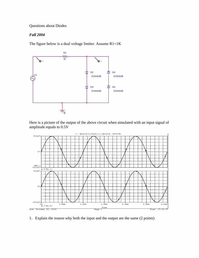
Questions about Diodes Fall 2004 The figure below is a dual voltage limiter. Assume R1=1K
0
V1
V
R1
1k
D2
D1N4148
D5
D1N4148
D3
D1N4148
V
D4
D1N4148
Here is a picture of the output of the above circuit when simulated with an input signal of amplitude equals to 0.5V
1. Explain the reason why both the input and the output are the same (2 points)
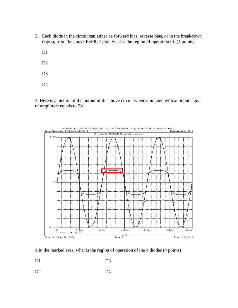
2. Each diode in the circuit can either be forward bias, reverse bias, or in the breakdown
region, from the above PSPICE plot, what is the region of operation of: (4 points)
D1 D2 D3 D4
3. Here is a picture of the output of the above circuit when simulated with an input signal of amplitude equals to 5V
4.In the marked area, what is the region of operation of the 4 diodes (4 points) D1 D3 D2 D4

5. What is the value of current through the resistor R1 when the input voltage is at the values listed below. Assume Von for each diode is 0.7V 3 volts ( 2 points) -3 volts (2 points) 0.2V (2 points) -0.2V (2 points) If the 4 diodes (D1-D4) are replaced with one zener diode. The input and output will be as shown in the figure below
0
V V
D6
D1N750V2
FREQ = 1KVAMPL = 10VOFF = 0
R1
1k

6.What is the current in the two marked regions ( 4 points) 1. 2.
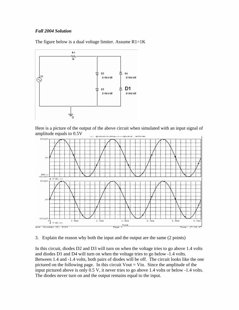
Fall 2004 Solution The figure below is a dual voltage limiter. Assume R1=1K
Here is a picture of the output of the above circuit when simulated with an input signal of amplitude equals to 0.5V
3. Explain the reason why both the input and the output are the same (2 points) In this circuit, diodes D2 and D3 will turn on when the voltage tries to go above 1.4 volts and diodes D1 and D4 will turn on when the voltage tries to go below -1.4 volts. Between 1.4 and -1.4 volts, both pairs of diodes will be off. The circuit looks like the one pictured on the following page. In this circuit Vout = Vin. Since the amplitude of the input pictured above is only 0.5 V, it never tries to go above 1.4 volts or below -1.4 volts. The diodes never turn on and the output remains equal to the input.

4. Each diode in the circuit can either be forward bias, reverse bias, or in the breakdown
region, from the above PSPICE plot, what is the region of operation of: (4 points)
D1: reverse bias (off) D2: reverse bias (off) D3: reverse bias (off) D4: reverse bias (off)
3. Here is a picture of the output of the above circuit when simulated with an input signal of amplitude equals to 5V

4.In the marked area, what is the region of operation of the 4 diodes (4 points) D1: reverse bias (off) D2: forward bias (on) D3: forward bias (on) D4: reverse bias (off) 5. What is the value of current through the resistor R1 when the input voltage is at the values listed below. Assume Von for each diode is 0.7V 3 volts ( 2 points) I = (3-1.4)/1K = 1.6mA -3 volts (2 points) I = (-3-(-1.4)) = -1.6mA 0.2V (2 points) I = 0 mA -0.2V (2 points) I = 0 mA If the 4 diodes (D1-D4) are replaced with one zener diode. The input and output will be as shown in the figure below
0
V V
D6
D1N750V2
FREQ = 1KVAMPL = 10VOFF = 0
R1
1k

I am assuming that region 1 is the upper region which cuts off at about 4.7 volts and region 2 is the lower region which cuts off at about -0.7 volts. 6.What is the current in the two marked regions ( 4 points) Method I: Assume that we are at the extremes where Vin = 10V or -10V 1. I = [10-4.7]/1K = 5.3mA 2. I = [-10 – (-0.7)] / 1K = -9.3 mA Method II: Assume the general case, where Vout is a function of Vin. 1. I = [ Vin-4.7 ] / 1K 2. I = [Vin – (-0.7) ] / 1K = [ Vin + 0.7 ] / 1K
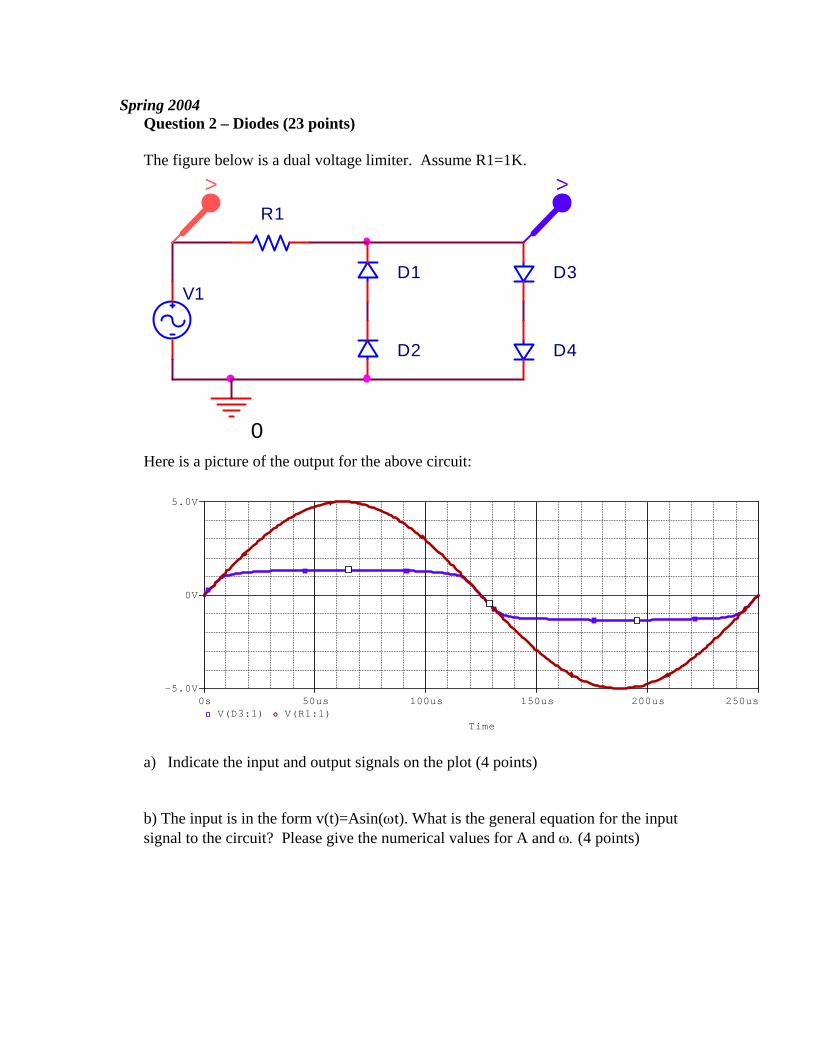
Spring 2004 Question 2 – Diodes (23 points) The figure below is a dual voltage limiter. Assume R1=1K.
V1
V V
R1
0
D3
D2 D4
D1
Here is a picture of the output for the above circuit:
Time
0s 50us 100us 150us 200us 250usV(D3:1) V(R1:1)
-5.0V
0V
5.0V
a) Indicate the input and output signals on the plot (4 points) b) The input is in the form v(t)=Asin(ωt). What is the general equation for the input signal to the circuit? Please give the numerical values for A and ω. (4 points)

c) Each diode in the circuit has a forward bias region, a reverse bias region and a breakdown region. Answer the following questions with regard to the circuit and PSpice output on the previous page.
i) Which of the three regions does not affect the input signal pictured in the output on the previous page? (1 point)
ii) Circle and label the area on the PSpice output where diode D1 and D2 are
in the reverse bias region. (2 points) iii) Circle and label the area on the PSpice output where diode D3 and D4 are
in the reverse bias region. (2 points)
iv) Circle and label the area on the PSpice output where diodes D1 and D2 are in the forward bias region. (2 points)
v) Circle and label the area on the PSPice output where the diodes D3 and D4
are in the forward bias region. (2 points) d) What is the value of the current through the resistor when the input voltage is at the values listed below. Assume Von for each diode is 0.7 Volts.
i) 4 volts (3 points) ii) -4 volts (3 points)

Spring 2004 solution Question 2 – Diodes (23 points) The figure below is a dual voltage limiter. A: Assume R1=1K. B: Assume R1=3K.
V1
V V
R1
0
D3
D2 D4
D1
Here is a picture of the output for the above circuit:
b) Indicate the input and output signals on the plot (4 points) b) The input is in the form v(t)=Asin(ωt). What is the general equation for the input signal to the circuit? Please give the numerical values for A and ω. (4 points) A=5V T=250us=.25ms=(1/4)ms f= 4K Hz ω=2πf=8Kπ rad/sec=25.1Krad/sec v(t) = 5V sin( 25.1K t)

c) Each diode in the circuit has a forward bias region, a reverse bias region and a breakdown region. Answer the following questions with regard to the circuit and PSpice output on the previous page.
vi) Which of the three regions does not affect the input signal pictured in the output on the previous page? (1 point)
breakdown region
vii) Circle and label the area on the PSpice output where diode D1 and D2 are
in the reverse bias region. (2 points) viii) Circle and label the area on the PSpice output where diode D3 and D4 are
in the reverse bias region. (2 points)
ix) Circle and label the area on the PSpice output where diodes D1 and D2 are in the forward bias region. (2 points)
x) Circle and label the area on the PSPice output where the diodes D3 and D4
are in the forward bias region. (2 points) d) What is the value of the current through the resistor when the input voltage is at the values listed below. Assume Von for each diode is 0.7 Volts.
iii) 4 volts (3 points)
A: R3=1K 4 – 2(0.7) = 2.6V I=2.6/1K I = 2.6mA B: R3=3K 4 – 2(0.7) = 2.6V I=2.6/3K I = 0.87mA
iv) -4 volts (3 points)
A: -4 – 2(-0.7) = -2.6V I=-2.6/1K I = -2.6mA A: -4 – 2(-0.7) = -2.6V I=-2.6/3K I = -0.87mA

Fall 2003 Question 2 -- Diodes (25 points) The figure below is a half wave rectifier.
0
V
R1
V
V1
D1
D1N4148
Let R1 = 2K. Here is the Capture/Pspice output for the above circuit:
Time
0s 0.2ms 0.4ms 0.6ms 0.8ms 1.0msV(D1:1) V(R1:2)
-4.0V
0V
4.0V
a) Indicate the input and output signals on the plot. (4 points) b) The input is in the form v(t) = A sin(ωt). What is the general equation for the
input signal to this circuit? Please give numerical values for A and ω. (4 points)

c) How would you fill in the following Capture parameters to get this output plot? Note: Any reasonable step size will be accepted. (3 points)
d) A diode has three active regions: forward bias region, reverse bias region, and
breakdown region. Answer the following two questions in regard to the circuit and PSpice output on the previous page.
i. Which of the three regions does not affect the input signal pictured in the
Pspice output on the previous page? (2 points)
ii. Circle and label the areas on the output signal when the diode is in the other two regions. (4 points)
e) What is the value of the current through the resistor when the input voltage is at
the values listed below. Assume Von for the diode is 0.7V.
i. 4 volts (4 points) ii. –4 volts (4 points)

Fall 2003 Solution Question 2 -- Diodes (25 points) The figure below is a half wave rectifier.
0
V
R1
V
V1
D1
D1N4148
Let R1 = 2K. Here is the Capture/Pspice output for the above circuit:
f) Indicate the input and output signals on the plot. (4 points) g) The input is in the form v(t) = A sin(ωt). What is the general equation for the
input signal to this circuit? Please give numerical values for A and ω. (4 points)
A = 4V w=2π/T=2π/1ms=2Kπ rad/sec v(t) = 4V sin(2Kπ t) = 4V sin(6.28Kt)
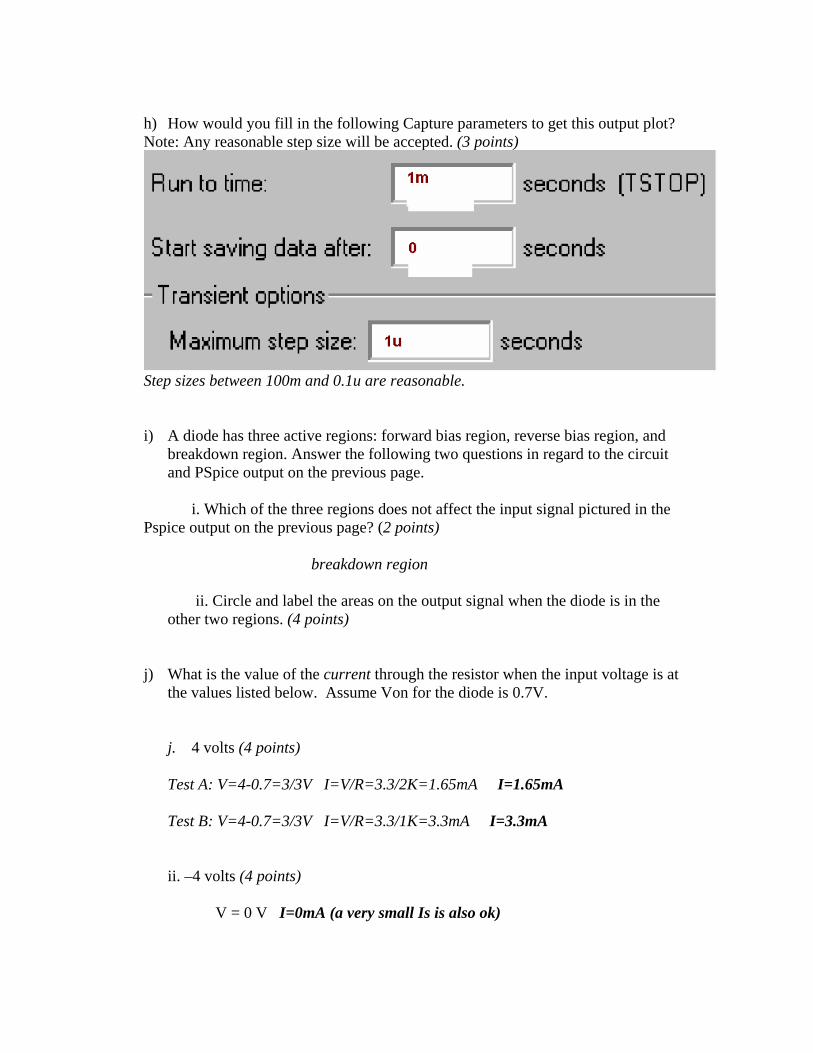
h) How would you fill in the following Capture parameters to get this output plot? Note: Any reasonable step size will be accepted. (3 points)
Step sizes between 100m and 0.1u are reasonable. i) A diode has three active regions: forward bias region, reverse bias region, and
breakdown region. Answer the following two questions in regard to the circuit and PSpice output on the previous page.
i. Which of the three regions does not affect the input signal pictured in the
Pspice output on the previous page? (2 points)
breakdown region
ii. Circle and label the areas on the output signal when the diode is in the other two regions. (4 points)
j) What is the value of the current through the resistor when the input voltage is at
the values listed below. Assume Von for the diode is 0.7V.
j. 4 volts (4 points) Test A: V=4-0.7=3/3V I=V/R=3.3/2K=1.65mA I=1.65mA
Test B: V=4-0.7=3/3V I=V/R=3.3/1K=3.3mA I=3.3mA ii. –4 volts (4 points) V = 0 V I=0mA (a very small Is is also ok)

Fall 2002 2. Diodes (25 points) In the full wave rectifier below, each of the diodes turns on at 0.6 volts and the resistances are as shown.
a. (10 points) Draw a circuit which shows: i) the positive half cycle of the circuit. (when current flows in the positive direction). ii) the negative half cycle of the circuit. (when current flows in the negative direction.) b. (9 points) What will the voltage between V+
out and V-out be when
i.) Vin = 5 V ii) Vin = -5 V iii) Vin = 0V

c. Which of the plots below represents Vin and Vout for this circuit (6 points)?

Fall 2002 Solution (not available)

Spring 2002 2. Diodes (25 points) In the figure below, each of the diodes turns on at between 0.6 volts and R=2k.
1. Give the voltage at Vout for each of the following values of the input voltage, Vin (2 points each). a. Vin = 5 Volts b. Vin = 2 Volt c. Vin = 1Volts d. Vin = 0.4 Volts e. Vin = 0 Volts f. Vin = -0.4 Volts g. Vin = -1 Volt h. Vin = -2 Volt 2. Use the above data to plot Vout vs Vin for the range –5 <=Vin <= +5 (4 points)

3. Which of the plots below represents Vout for this circuit (5 points)?
Time
0s 100us 200us 300us 400us 500usV(V1:+) V(D9:1)
-5.0V
0V
5.0V
Time
0s 100us 200us 300us 400us 500usV(V1:+) V(D9:1)
-5.0V
0V
5.0V
Time
0s 100us 200us 300us 400us 500usV(V1:+) V(D9:1)
-5.0V
0V
5.0V

Spring 2002 solution (not available)

Fall 2001 Solution