Queensland Electricty Metering Manual - …...Queensland Electricity Metering Manual Check this is...
67
Transcript of Queensland Electricty Metering Manual - …...Queensland Electricity Metering Manual Check this is...


Queensland Electricity Metering Manual
Check this is the latest version before use. EX Manual 01812 Ver 2 EE NA000403R510 Ver 2
Joint document between Energex and Ergon Energy Energex Limited ABN 40 078 849 055 Ergon Energy Corporation Limited ABN 50 087 646 062
THIS PAGE HAS BEEN DELIBERATELY LEFT BLANK

Queensland Electricity Metering Manual
Check this is the latest version before use. i EX Manual 01812 Ver 2 EE NA000403R510 Ver 2
Joint document between Energex and Ergon Energy Energex Limited ABN 40 078 849 055 Ergon Energy Corporation Limited ABN 50 087 646 062
Table of Contents
Foreword .................................................................................................................... 1 Purpose and Scope ................................................................................................... 2 Definitions, Abbreviations and Acronyms .............................................................. 2 References ................................................................................................................. 2 1. IMPORTANT INFORMATION .............................................................................. 3
Use of this document ........................................................................................... 3 1.1. Scope .................................................................................................................. 3 1.2. Failure to comply with this manual ....................................................................... 3 1.3. Exceptional Circumstances .................................................................................. 3 1.4. Historic Buildings ................................................................................................. 4 1.5. Distributors Contact Details for QEMM Correspondence ..................................... 5 1.6. Revisions and alterations ..................................................................................... 5 1.7. Drawings ............................................................................................................. 5 1.8.
2. Metering Requirements ...................................................................................... 7 General ................................................................................................................ 7 2.1. Metering Determination ....................................................................................... 7 2.2. Controlled loads ................................................................................................... 7 2.3. Customers Energy Management Systems ........................................................... 8 2.4. Sealing of Metering Equipment ............................................................................ 8 2.5. Metering Isolation ................................................................................................ 8 2.6. Metering Active and Neutral Requirements .......................................................... 8 2.7. Size of Direct Connected Meter Wiring ................................................................ 8 2.8. Metering requirements for a Builder’s Temporary Service (BTS) ......................... 9 2.9.
Plug-in Metering .................................................................................................. 9 2.10. Card Operated Metering ...................................................................................... 9 2.11. Metering and Control Equipment - Accommodation ........................................... 10 2.12. Metering and Control Equipment – Spacing Requirements ................................ 10 2.13. Current Transformer Metering - General Requirements ..................................... 10 2.14. Current Transformer Equipment ........................................................................ 11 2.15. Current Transformer Selection ........................................................................... 11 2.16. Current Transformer Metering - Housing ........................................................... 11 2.17. Current Transformer Metering – Installation Requirements ................................ 13 2.18. Current Transformer Metering – Meter Panels ................................................... 13 2.19. Spacing between Meters and Heavy Current Carrying Conductors ................... 14 2.20. Current Transformer Metering – Additional Requirements ................................. 15 2.21.
Electrical Contractor’s LV CT Metering Check Sheet .................................................... 18 Appendix A - Glossary of Terms ............................................................................ 58 Appendix B - Amendment record .......................................................................... 63

Queensland Electricity Metering Manual
Check this is the latest version before use. Page 1 of 63 EX Manual 01812 Ver 2 EE NA000403R510 Ver 2
Joint document between Energex and Ergon Energy Energex Limited ABN 40 078 849 055 Ergon Energy Corporation Limited ABN 50 087 646 062
FOREWORD The Queensland Electricity Metering Manual (QEMM) has been compiled in conjunction with Energex and Ergon Energy Network.
Note: Printed versions of the QEMM are “uncontrolled copies” - the latest version is available onthe Energex website (https://www.energex.com.au/) or the Ergon Energy website (https://www.ergon.com.au/).
Safety
In all activities undertaken, the safety of our employees, contractors, energy customers and the community is paramount. Safety is our number one value and there is a commitment to ensuring that "safety must come first" to achieve a no injuries workplace. With our member we have developed Policies, Standards and Work Practices that our workers are required to follow to ensure the safety of themselves, other workers, energy customers and the community. We trust that electrical contractors and persons in control of sites will appreciate that our workers will not undertake any work in a situation where there are uncontrolled risks inconsistent with our safe systems of work.
Disclaimer
Whilst the QEMM contains material relevant to the NEM rules, Queensland electricity industry legislation, codes of practice and standards, it is not intended to provide legal advice on how electrical contractors can meet their own statutory obligations or comply with legislation, codes of practice or industry standards such as AS/NZS 3000 (Wiring Rules).
The QEMM does not provide advice for the purposes of section 68 of the Electrical Safety Regulation 2013. The Electrical Safety Act 2002, Electrical Safety Regulation 2013 and associated codes of practice establish requirements for electrical safety and place obligations on employers, self-employed persons and others. These documents may be obtained from the Queensland Government website (www.worksafe.qld.gov.au).
Whilst care has been taken in the preparation of the QEMM, the distribution entities do not guarantee that the information contained in the QEMM is accurate, complete or up to date at time of publication. To the extent permitted by the relevant legislation, the distributor will not be responsible for any loss, damage, cost or expense incurred as a result of any error, omission or misrepresentation in relation to the information contained in the QEMM.
Copyright
Copyright © 2018. Energex Limited and Ergon Energy Corporation Limited. This publication is copyright. Except as permitted under the Copyright Act 1968 no part of this publication may be reproduced by any process without the specific written permission of the copyright owner.
All rights reserved.

Queensland Electricity Metering Manual
Check this is the latest version before use. Page 2 of 63 EX Manual 01812 Ver 2 EE NA000403R510 Ver 2
Joint document between Energex and Ergon Energy Energex Limited ABN 40 078 849 055 Ergon Energy Corporation Limited ABN 50 087 646 062
PURPOSE AND SCOPE The purpose of this manual is to promote industry uniformity through standardisation of practices throughout Queensland. The document is for use by Electrical Contractors, Consulting Engineers, Architects, Distribution Networks, Metering Providers and others directly concerned with electrical installations that are connected, or are to be connected, to the respective supply network.
Metering installation compliance and obligations contained in this manual form part of Meter Providers accreditation oblibations under the National Electricity Rules.
DEFINITIONS, ABBREVIATIONS AND ACRONYMS Unless otherwise stated, definitions, abbreviations and acronyms used in AS/NZS 3000 (Wiring Rules) and the current Legislation referenced in the QEMM have the same meaning when used in this document.
Refer to the Glossary of Terms for general definitions.
Note: Words and terms defined in the Glossary are identified within the text by italicising (e.g. distributor).
REFERENCES The document is to be read in cojunction with the Queensland Electricity Connection Manual (QECM) published from time to time by Energex Limited and Ergon Energy Corporation Limited.

Queensland Electricity Metering Manual
Check this is the latest version before use. Page 3 of 63 EX Manual 01812 Ver 2 EE NA000403R510 Ver 2
Joint document between Energex and Ergon Energy Energex Limited ABN 40 078 849 055 Ergon Energy Corporation Limited ABN 50 087 646 062
1. IMPORTANT INFORMATION Use of this document 1.1.
This document is to be read in conjunction with the current:
A. Australian Standards, in particular AS/NZS 3000 (Wiring Rules). B. Relevant Legislation and respective Regulations and Codes (see References in
QECM). C. The National Electricity Rules. D. The QECM and addendums published in relation to specific topics (on and from
the date they are published). Note: The requirements of the Queensland Electricity Legislation are to be considered in the design, installation, operation and maintenance of the customer’s electrical installation
This is a self-contained document except where it specifically refers to other related documents and supersedes previous versions of both the Energex and Ergon Energy Electricity Connection and Metering Manuals.
This document applys to all premises connected to Energex and Ergon Networks including all premises connected to an Isolated Power System, or part of the Mt Isa supply network.
Scope 1.2.This document provides guidelines for metering arrangements of a customer's installation.
Where departures from these guidelines may be necessary, prior consultation with the Meter Provider will be required.
Failure to comply with this manual 1.3.Should an installation not satisfy the requirements of these and/or other applicable rules, the installation of metering equipment may be delayed or withheld until such time as the non-compliance(s) has been rectified.
Exceptional Circumstances 1.4.In exceptional circumstances the stated requirements contained within the QEMM may be waived and/or modified by the submission of a written request to the relevant distributor.
The request shall include all of the following:
A. A detailed statement of the reasons why non-compliance with this manual is sought.
B. Full details and diagrams, as necessary, showing the specific aspect of a requested variation to the QEMM.
C. Property location details. No action or variation should be undertaken until a written approval from the Meter Provider, has been received.
Note: Any variation approval will only apply to the individual property as listed in the request (i.e. it does not cover, or set any precedent, for any other installation).
Request for an interpretation of the QEMM 1.4.1
A request for an interpretation of the QEMM must be made in writing to the relevant distributor. A reply will be provided by the distributor within 10 working days from receipt of the written request.

Queensland Electricity Metering Manual
Check this is the latest version before use. Page 4 of 63 EX Manual 01812 Ver 2 EE NA000403R510 Ver 2
Joint document between Energex and Ergon Energy Energex Limited ABN 40 078 849 055 Ergon Energy Corporation Limited ABN 50 087 646 062
Request for dispensation from the QEMM 1.4.2
A request for dispensation from the requirements of the QEMM must be made in writing to the relevant distributor. A reply will be provided within 10 working days from receipt of the written request.
Request for an QEMM amendment 1.4.3
A request for an amendment of the QEMM must be made in writing to the relevant distributor. Acknowledgement of receipt of the amendment will be provided within 10 working days from receipt of the written request.
Historic Buildings 1.5.The electrical contractor should consult the owner if the building appears to have historical significance. Historic buildings may require the requirements of this manual be waived and/or modified for meter positions etc.
Similarly, flora protected by a Vegetation Protection Order may require special arrangements for the erection or alteration of overhead or underground services.
Electrical contractors should contact the distributor before starting work (See Exceptional Circumstances above).

Queensland Electricity Metering Manual
Check this is the latest version before use. Page 5 of 63 EX Manual 01812 Ver 2 EE NA000403R510 Ver 2
Joint document between Energex and Ergon Energy Energex Limited ABN 40 078 849 055 Ergon Energy Corporation Limited ABN 50 087 646 062
Distributors Contact Details for QEMM Correspondence 1.6.Contact details for QEMM amendments or enquiries are:
Energex: Email [email protected]
Write to: Energex Limited QECM Request
GPO Box 1461
BRISBANE Qld 4001
Ergon Energy: Email: [email protected]
Write to: Ergon Energy QECM Request
PO Box 308
ROCKHAMPTON Qld 4700 Revisions and alterations 1.7.
Energex and Ergon Energy reserve the right to revise this publication. The current edition of this document is available on the Energex website at www.energex.com.au or the Ergon Energy website at www.ergon.com.au.
Drawings 1.8.The drawings have been placed in the body of the document after the section to which they are most relevant but may be referred to in more than one section.
Queensland Electricity Metering Manual
Check this is the latest version before use. Page 6 of 63 EX Manual 01812 Ver 2 EE NA000403R510 Ver 2
Joint document between Energex and Ergon Energy Energex Limited ABN 40 078 849 055 Ergon Energy Corporation Limited ABN 50 087 646 062
THIS PAGE HAS BEEN DELIBERATELY LEFT BLANK

Queensland Electricity Metering Manual
Check this is the latest version before use. Page 7 of 63 EX Manual 01812 Ver 2 EE NA000403R510 Ver 2
Joint document between Energex and Ergon Energy Energex Limited ABN 40 078 849 055 Ergon Energy Corporation Limited ABN 50 087 646 062
2. METERING REQUIREMENTS General 2.1.
This section includes metering requirements, for specific information contact the metering provider.
Where a customer directs a retailer to request metering or tariff changes, any alterations to the customer’s switchboard installation or meter enclosure shall be the customer’s responsibility (e.g. removal of asbestos contaminated waste) (Refer to Clause 6.12). Metering equipment deemed to be necessary by the metering provider to record electricity consumption shall be supplied and maintained by the metering provider and shall remain their property.
Network devices deemed to be necessary to control electricity consumption shall be supplied and maintained by the distributor and shall remain their property. All meter and network device active terminals shall be connected directly to the Metering Isolation Link or Metering Active Link for direct connected installations.
Where it is known that a single tariff two or three-phase supply will be required at the time of initial connection, provision for the metering shall be installed at this time in accordance with the requirements of the metering provider. It is anticipated that this will be a polyphase meter. All phases of a service line are required to be connected at the initial connection of the premises.
All metering and control equipment shall be back-wired and mounted on a hinged panel attached to a metering enclosure or a switchboard frame.
For multiple tenancy installations, access to sub boards within tenancies may be required for verification of submains and metering. (Refer to Clause 2.7).
Where metering or control equipment is no longer required, the metering provider shall be contacted to arrange for its removal.
Customer's ancillary equipment such as surge diverters, voltmeters, phase failure relays etc. shall be connected on the load side of the revenue metering equipment. Customer owned current transformers for energy management are permitted on the line side of revenue metering equipment at multiple tenancy installations.
Metering Determination 2.2.Customer’s installations other than those approved by the distributor as suitable for unmetered supply (e.g. non-standard installations located on public land (refer to Clauses 2.6 and 2.9)) will be metered by one of the following methods:
(a) Direct connected meters; or
(b) Current transformer metering; or
(c) HV current transformer - voltage transformer metering. (Refer to QEMM).
The customer (or their electrical contractor) is responsible for determining and monitoring the installation’s load requirements, and method of metering (i.e. direct connected or current transformer metering). This applies to new connections and/or alterations or additions. The customer may need to consult with the customer’s retailer at the earliest opportunity in order to determine their metering requirements.
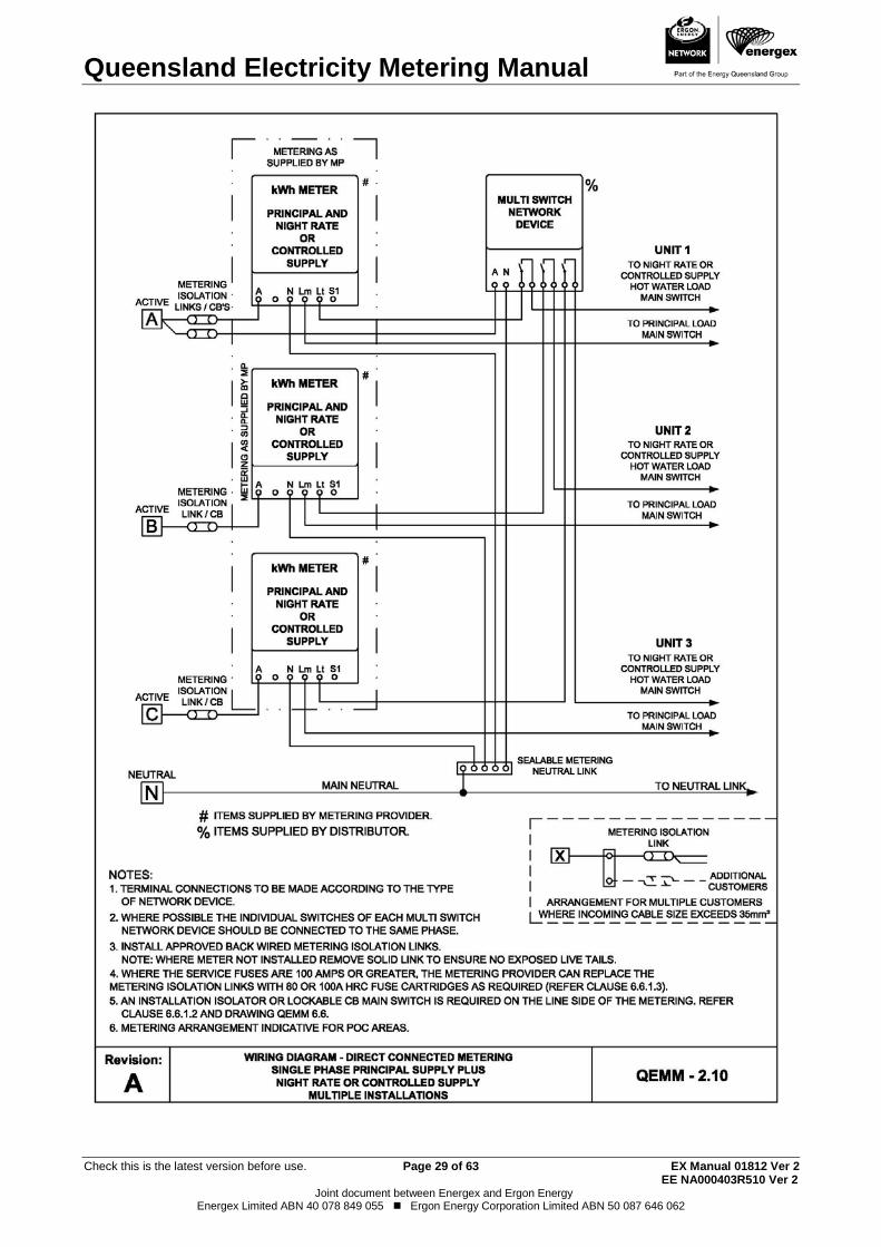
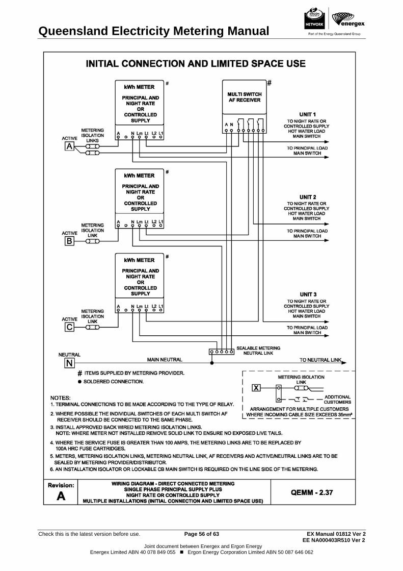
Controlled loads 2.3.Where controlled loads are required (Controlled Supply/Night Rate tariffs), provision for a separate network device shall be made (Refer to Drawing QEMM 2.0 for cable access drilling details). The network device will only be installed when the customer has requested controlled load as part of the EWR for the installation.

Queensland Electricity Metering Manual
Check this is the latest version before use. Page 8 of 63 EX Manual 01812 Ver 2 EE NA000403R510 Ver 2
Joint document between Energex and Ergon Energy Energex Limited ABN 40 078 849 055 Ergon Energy Corporation Limited ABN 50 087 646 062
The QEMM contains more detail on requirements for connection of controlled loads.
Customers Energy Management Systems 2.4.A customer requiring an interface with the metering provider's facilities should contact the metering provider.
Sealing of Metering Equipment 2.5.The metering provider will seal all the metering equipment and may seal cubicles or panels which house revenue metering equipment, or unmetered sections of a switchboard. It is an offence to break or interfere with any seal unless authorised by the metering provider.
Meters, network devices, metering isolation links, metering neutral links, metering active links, voltage circuit fuses and contactors associated with the metering, and which are required as a condition of a supply arrangement (e.g. controlled supply), are typical of equipment that requires sealing.
The customer shall make provision for the sealing of all current transformer metering panels, dedicated current transformer and voltage transformer chambers and HV metering panels.
Metering Isolation 2.6.To facilitate the requirements of the Electrical Safety Act 2002 and Electrical Safety Regulation 2013 for performing electrical work, and the Electricity Act 1994 and Electricity Regulation 2006, supply to the revenue metering equipment for each customer is to be capable of being individually isolated.
All metering shall be connected with suitable active isolation devices connected to the line side of the metering to allow safe access to the metering equipment.
Isolation of Direct Connected Metering 2.6.1
Direct connected metering shall be installed on the line side of the individual installation’s main switches and be capable of being isolated as per the QECM
Isolation of Current Transformer Metering 2.6.2
Current Transformer metering shall be capable of being individually isolated by a suitable isolator or main switch. All isolation equipment shall be clearly identified and readily accessible and shall be installed and maintained by the customer and be capable of being isolated as per the QEMM
Metering Active and Neutral Requirements 2.7. Metering Neutral and active links, and appropriate labelling is required as per the QECM
Size of Direct Connected Meter Wiring 2.8.The meter wiring for direct connected metering shall be PVC insulated copper cable from these standard sizes:
4mm2 7/0.85
6mm2 7/1.04
10mm2 7/1.35
16mm2 7/1.70
Insulated flexible cables are approved for use for 10, 16 & 25mm2 provided that one long or two short soft-form un-insulated bootlace pins (end sleeves) are securely crimped snuggly against each other onto each cable tail by the electrical contractor. The use of two bootlace pins per cable tail will allow the use of standard length pins while still allowing the required length to maintain secure connection to the meter terminal screws. Upon installation by the Distributor, any excess length of pins will be trimmed to suit the depth of the meter being used. An appropriate crimping tool must be used. (Refer to AS/NZS 3000 (Wiring Rules)).

Queensland Electricity Metering Manual
Check this is the latest version before use. Page 9 of 63 EX Manual 01812 Ver 2 EE NA000403R510 Ver 2
Joint document between Energex and Ergon Energy Energex Limited ABN 40 078 849 055 Ergon Energy Corporation Limited ABN 50 087 646 062
Active and load meter wiring for direct connected metering shall not exceed 25mm². Not more than one active conductor may be connected to any one line side terminal of a direct connected meter, except where parallel conductors no larger than 10mm2 are used.
Compressed (compacted) or hard drawn conductors shall not be used as meter wiring (must be flexible enough to bend into the meter terminals).
Aluminium cables are not permitted for connection directly into meter terminals.
Metering requirements for a Builder’s Temporary Service (BTS) 2.9.Builder’s Temporary Services are required to comply with all metering requirements of the QEMM for typical metering installations. These requirements include but are not limited to:
- All metering and control equipment shall be back-wired and mounted on a hinged panel attached to a metering enclosure or a switchboard frame. (Refer to Clause 2.1).
- A metering isolation link per phase shall be connected to the line side of the metering. (Refer to Clause 2.6).
Builder’s Temporary Services meter panels do not need to be dedicated to revenue metering equipment unless they are intended to be installed in the permanent position.
Plug-in Metering 2.10.Plug-in kilowatt hour meters are only available on existing installations where the plug-in type bases are already installed.
Card Operated Metering 2.11.In Ergon Energy's Far North Queensland region, card operated meters (COMs) will be supplied for designated remote communities and most isolated generation sites in the Torres Strait Islands.
The majority of single phase card operated meters, are supplied as plug-in meters and require a plug-in meter socket to be provided and installed by the customer (3 jaw with A, N & L terminals for single tariff installations and 4 jaw with A, N, L & 1 terminals for two tariff installations) Refer to AS 1284 part 4 figure 2.1. Ergon Energy stock recovered plug-in sockets for use by Electrical Contractors who cannot source these items. Card operated meters are progressively being converted to bottom connected meters (by community) and hence will no longer require the supply and installation of a plug-in socket. Contact Ergon Energy to ascertain if a plug-in socket is required. Commercial installations requiring special tariffs or current transformer metering will not use card operated meters. Temporary Builder’s Supplies in card operated meter areas shall have card operated meters installed with commercial tariffs to apply.
Requests for exemptions can be lodged for critical loads (e.g. sewerage pumps, unmanned communications sites etc) so that card operated meters are not used (refer to Clause 1.4). A metering isolation link is required to be installed on the line side of all card operated meters.
In general Ergon Energy will provide one service to a community title scheme or
cluster development installation with card operated meters.
Where a cluster or community title scheme development with card operated meters consists of a number of tenanted buildings a meter position located on common ground for each building may be permitted.
The following meter positions will also be acceptable:

Queensland Electricity Metering Manual
Check this is the latest version before use. Page 10 of 63 EX Manual 01812 Ver 2 EE NA000403R510 Ver 2
Joint document between Energex and Ergon Energy Energex Limited ABN 40 078 849 055 Ergon Energy Corporation Limited ABN 50 087 646 062
(i) The main switchboard located on common ground and all metering equipment installed at this position.
(ii) The main switchboard and the first metering point located on common ground and subsequent metering points located either on each building or as otherwise approved by Ergon Energy.
Note: - A single community meter position is preferred, however approval may be granted for an additional community meter where a single position is not practical. Each community meter will be treated as a separate account for billing purposes.
To clarify the required metering type in the remote communities and isolated generation sites in Far North Queensland contact Ergon Energy Customer Service. (Refer to page 1 for contact details).
Metering and Control Equipment - Accommodation 2.12.The customer shall provide and maintain at their expense, suitable space, housing, mounting and connecting facilities to accommodate meters and control equipment for each supply arrangement (e.g. general and controlled supplies).
Metering and Control Equipment – Spacing Requirements 2.13.Item A.3 of the "Specification for Metallic Enclosures for Meters in Direct Connected Installations" in QECM Appendix A, specifies minimum space requirements for metering equipment on direct connected installations.
Clause 2.19 specifies minimum space requirements for meter panels for low voltage current transformer metering.
Minimum space requirements for mounting of meters and control equipment are shown in TABLE 2.1.
TABLE 2.1
Meter and Network Device Details
Height (mm)
Width (mm)
Depth (mm)
Approx. Weight (kg)
Single Phase Meter 255 150 130 1.5
Polyphase Meter 285 180 135 2.1
A minimum clearance of 25mm is required between any item of metering or control equipment.
The minimum clearance around the ends of metering isolation links shall be 40mm minimum.
Exception: Metering isolation links associated with each NMI can be mounted side by side with no clearance between provided the minimum clearance around the ends of metering isolation links is 40mm minimum.
Current Transformer Metering - General Requirements 2.14.The following procedures are to be adopted when assessing the metering requirements, for new installations or additional load for an existing installation, and arranging for the installation of current transformer metering.
In general, calculated loads greater than 110A per phase or actual loads greater than 80A per phase will require current transformer metering. Contact the metering provider for further information.

Queensland Electricity Metering Manual
Check this is the latest version before use. Page 11 of 63 EX Manual 01812 Ver 2 EE NA000403R510 Ver 2
Joint document between Energex and Ergon Energy Energex Limited ABN 40 078 849 055 Ergon Energy Corporation Limited ABN 50 087 646 062
Current Transformer Equipment 2.15.The metering provider will supply the current transformers, E.S.A.A. pattern test block, voltage circuit fuses with HRC cartridges, fuse sealing blocks with covers, current transformer ratio and neutral identification labels.
Current Transformer Selection 2.16.In general the standard current transformers supplied by the distributor or the metering provider are E.S.A.A type "S", "T" and "W". TABLE 2.2 below details the type, ratio and accuracy range of current transformers supplied.
TABLE 2.2
TYPE OF CT
CT RATIO
CLASS (AS 60044)
ACCURACY RANGE OF
CT (AMPS)
MAX. 3 PHASE LOAD (kVA)
MAX. SINGLE PHASE LOAD
(AMPS) S (long range) 200/5 0.5S ext 200% 2 - 400 250 350
T (long range) 800/5 0.5S ext 200% 8 - 1600 1000 1400
W (long range) 1500/5 0.5S ext 200% 15 - 3000 2000 3000
Current Transformer Metering - Housing 2.17.
On new installations and where major alterations are to be carried out, each set of 2.17.1current transformers and meter voltage fuses are required to be mounted in a separate dedicated metering chamber. This chamber is to enclose only the metering provider’s equipment. (Refer to Drawing QEMM 2.1).
In general, each current transformer chamber is a dedicated chamber for one NMI and as such, no other equipment or wiring is permitted in or to pass through the chamber, however, cables enclosed in a continuous metal duct located in a back corner of the current transformer chamber are permitted. (Refer to TABLE 2.4).
Current transformer chambers shall be labelled to indicate the presence of the 2.17.2revenue metering current transformers and access panels shall have provision for sealing. The electrical contractor or switchboard manufacturer shall supply and install labels stating "Revenue Metering Current Transformers" on current transformer chambers.
To allow commissioning and testing of current transformer metering installations to 2.17.3be performed safely, all live low voltage parts within current transformer chambers are to be individually insulated (insulation must completely cover all live parts). Heat shrink insulation is acceptable for insulating busbars. All bolted busbar or cable connections are to be covered with non-adhesive insulation secured in place by cable ties.
A non-conductive insulated barrier alone (removable cover over CT chamber) is not an acceptable method of insulation.
Where a removable cover is used to enclose the dedicated metering current 2.17.4transformer chamber it shall be fitted with a minimum of two handles to allow safe removal without disconnecting supply. This requirement does not apply to hinged
Queensland Electricity Metering Manual
Check this is the latest version before use. Page 12 of 63 EX Manual 01812 Ver 2 EE NA000403R510 Ver 2
Joint document between Energex and Ergon Energy Energex Limited ABN 40 078 849 055 Ergon Energy Corporation Limited ABN 50 087 646 062
covers. Locks are not permitted as a means of securing current transformer chambers due to the difficulty in obtaining access. (Refer to Clause 2.5 for sealing requirements).
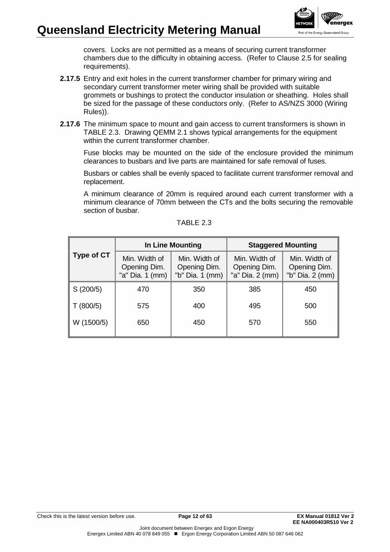
Entry and exit holes in the current transformer chamber for primary wiring and 2.17.5secondary current transformer meter wiring shall be provided with suitable grommets or bushings to protect the conductor insulation or sheathing. Holes shall be sized for the passage of these conductors only. (Refer to AS/NZS 3000 (Wiring Rules)).
The minimum space to mount and gain access to current transformers is shown in 2.17.6TABLE 2.3. Drawing QEMM 2.1 shows typical arrangements for the equipment within the current transformer chamber.
Fuse blocks may be mounted on the side of the enclosure provided the minimum clearances to busbars and live parts are maintained for safe removal of fuses.
Busbars or cables shall be evenly spaced to facilitate current transformer removal and replacement.
A minimum clearance of 20mm is required around each current transformer with a minimum clearance of 70mm between the CTs and the bolts securing the removable section of busbar.
TABLE 2.3
Type of CT
In Line Mounting Staggered Mounting
Min. Width of Opening Dim.
"a" Dia. 1 (mm)
Min. Width of Opening Dim.
"b" Dia. 1 (mm)
Min. Width of Opening Dim.
"a" Dia. 2 (mm)
Min. Width of Opening Dim.
"b" Dia. 2 (mm)
S (200/5) T (800/5) W (1500/5)
470
575
650
350
400
450
385
495
570
450
500
550
Queensland Electricity Metering Manual
Check this is the latest version before use. Page 13 of 63 EX Manual 01812 Ver 2 EE NA000403R510 Ver 2
Joint document between Energex and Ergon Energy Energex Limited ABN 40 078 849 055 Ergon Energy Corporation Limited ABN 50 087 646 062
To gain access to any current transformer or voltage circuit fuses it shall not be 2.17.7necessary to interrupt supply to a customer.
Current Transformer Metering – Installation Requirements 2.18.
Current Transformers 2.18.1
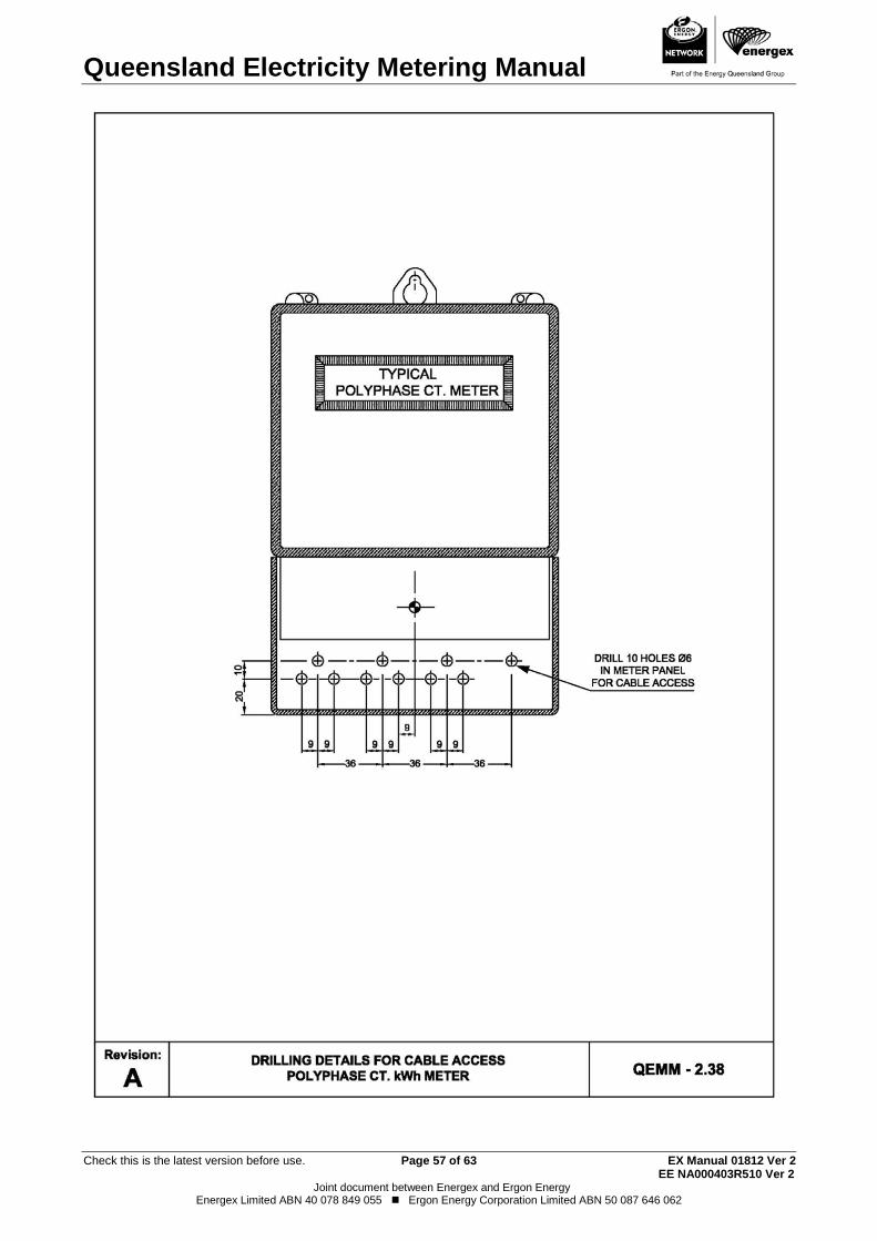
2.18.1.1 For general dimensions and mounting of current transformers for correct polarity refer to Drawings QEMM 2.2.
2.18.1.2 Current transformers shall be installed in a manner that facilitates replacement and mounted with suitably sized bolts, nuts and washers (self tapping screws are not permitted). A readily removable section of busbar as shown in Drawing QEMM 2.1 shall be provided within the current transformer chamber.
2.18.1.3 The current transformer secondary terminals shall be readily accessible and between 500mm and 1800mm from floor or ground level to allow access to terminals without undue risk to personnel when the switchboard is live.
Voltage Circuit Fuses 2.18.2
2.18.2.1 Voltage circuit fuses shall be mounted in such a manner that the fuse carriers may be removed, replaced and sealed without undue risk to personnel when the switchboard is live (generally facing the front of the chamber). (Refer to Clause 2.17.6 and Drawing QEMM 2.3).
2.18.2.2 A sealable fuse mounting block with HRC fuse cartridges shall be used on all new work and when upgrading existing installations. (Refer to Drawing QEMM 2.3).
2.18.2.3 The voltage circuit fuses shall be connected in such a manner that the energising current of the meter voltage coil will not be registered through the current transformers (i.e. should be connected to line side of the current transformers).
2.18.2.4 The supply conductors to the voltage circuit fuses shall be as short as practicable, in no case exceed 500mm in length, be separated from bare live busbars and shall originate from within the current transformer chamber. The conductors shall be double insulated and a minimum of 10mm² stranded cable of not more than 7 strands. No joints are permitted in these conductors. Where colour coded cables are unavailable, colour coding shall be provided by the use of appropriate coloured sleeving at both ends with a minimum length of 150mm at each end. (Refer to Drawing QEMM 2.4).
Current Transformer Metering – Meter Panels 2.19.
In general, meter panels for current transformer metering shall be installed remote 2.19.1from the switchboard. A separate meter panel is required for the metering equipment of each NMI.
Exception: Approval will be given for panels to be mounted within switchboards provided the:
(a) Switchboard is readily accessible. and
(b) The meter panel is dedicated for revenue metering equipment for that NMI; and
(c) The meter panel is shielded and/or sufficiently spaced from electromagnetic fields (refer to Clause 2.20); and

Queensland Electricity Metering Manual
Check this is the latest version before use. Page 14 of 63 EX Manual 01812 Ver 2 EE NA000403R510 Ver 2
Joint document between Energex and Ergon Energy Energex Limited ABN 40 078 849 055 Ergon Energy Corporation Limited ABN 50 087 646 062
(d) No panels or equipment (including meter panels) shall be mounted in front of the current transformer chamber.
Note: Direct connected meter wiring is permitted behind or on a current transformer meter panel provided it is for a secondary supply meter associated with the same customer (i.e. for the same NMI). All direct connected meter wiring behind the meter panel shall be separated and segregated from the current transformer meter wiring by enclosure within an earthed metal conduit, trunking or duct.
Unless specifically approved by the metering provider no customer’s equipment or wiring shall be permitted within the meter panel enclosure. (Refer to Drawing QEMM 2.5).
The panel shall be hinged on a vertical edge such that the panel can be opened at 2.19.2least 90° with the meters mounted. (A double offset hinged section may be required).
Meter panels shall be constructed of durable, non-conducting fire resistant material 2.19.3with low water absorption properties and shall not contain asbestos.
Meter Panels are required to have provision for sealing. 2.19.4
Clearances Required for Current Transformer Metering Panels 2.19.5
2.19.5.1 The clearance from the back of the meter panel to the back of the enclosure shall be a minimum of 75mm.
2.19.5.2 Where meters are enclosed, the clearance between the front of the meter panel and the back of the closed door (including any hat section) shall be not less than 175mm.
Spacing between Meters and Heavy Current Carrying Conductors 2.20.
The presence of external magnetic fields from nearby heavy current carrying 2.20.1conductors can cause errors in meter registration. To ensure maximum accuracy of the metering installation it is necessary to take adequate precautions against the effects of external magnetic fields.
Grouped Conductors 2.20.2
There are no special requirements for spacing or shielding where the current is carried by a three phase cable or three single core cables in a trefoil formation.
Separated Conductors 2.20.3
Where conductors of a circuit are physically separated, as in spaced single core cables or busbars, meters/meter must be suitably spaced from the conductors to reduce the effect of the magnetic field.
Where spacing alone cannot be achieved, magnetic shielding of suitable thickness may be used to reduce the minimum clearance by enclosing the conductors in a mild steel pipe or duct or enclosing the meters/meter wiring within a mild steel enclosure. Stainless steel, some alloy steels, aluminium, copper and other non-ferrous metals are not suitable materials for magnetic shielding.
The minimum spacing between revenue meters/meter wiring and conductors carrying heavy currents shall be derived from TABLE 2.4 - intermediate points may be obtained by interpolation.
TABLE 2.4

Queensland Electricity Metering Manual
Check this is the latest version before use. Page 15 of 63 EX Manual 01812 Ver 2 EE NA000403R510 Ver 2
Joint document between Energex and Ergon Energy Energex Limited ABN 40 078 849 055 Ergon Energy Corporation Limited ABN 50 087 646 062
Conductor
Current (A)
Min Spacing (mm)
No Shielding
Thickness of Shielding (mm)
1.2
2.5
5.0 Up to 150 100 - - -
400 500 375 250 125 600 700 525 350 175 1000 900 675 450 225 1500 1200 900 600 300 2000 1400 1050 700 350 3000 1700 1275 850 425 4000 2000 1500 1000 500
Note: Where the above spacing cannot be maintained within the switchboard, it is expected that the meter panel be installed remote from the switchboard. Particular care should be taken when the switchboard is constructed of aluminium or stainless steel.
Under no circumstances shall current transformer meter wiring be grouped with 2.20.4other conductors. Meter wiring run externally to the switchboard enclosure shall be contained within a separate conduit or cable trunking. (Refer to Clause 2.22.3 and 2.23.3.5).
Each individual set of current transformer meter wiring installed behind a meter panel containing multiple groups of current transformer meters, shall be grouped and separated from the other sets of current transformer meter wiring.
Current Transformer Metering – Additional Requirements 2.21.
For all current transformer metering (unless an agreement has been negotiated with 2.21.1the metering provider), the electrical contractor is responsible for the:
(a) Supply of the meter panel.
(b) Mounting of the meter panel.
(c) Mounting of the current transformers.
(d) Mounting of the voltage fuse block.
(e) Mounting of the test block.
(f) Supply and installation of all secondary wiring between the current transformers, test block and meter, including the voltage supply.
(g) Wiring of the meter panel (surface wiring of meter panels is not permitted).
Current transformers, metering test block, voltage circuit fuses and fuse sealing block will be made available to the electrical contractor to install.
To obtain LV current transformer metering equipment, electrical contractors are required to submit a CT Metering Equipment Order Form that is available from the metering provider.
Where the metering is more complex than a standard installation the electrical contractor shall consult with the metering provider. The contractor may be required to deliver a suitable metering panel to the metering provider for wiring and testing prior to being delivered on site.
Note: Paralleling and summation of current transformer metering is not acceptable as it compromises total metering accuracy.
Queensland Electricity Metering Manual
Check this is the latest version before use. Page 16 of 63 EX Manual 01812 Ver 2 EE NA000403R510 Ver 2
Joint document between Energex and Ergon Energy Energex Limited ABN 40 078 849 055 Ergon Energy Corporation Limited ABN 50 087 646 062
Current Transformer Metering Test Block 2.21.2
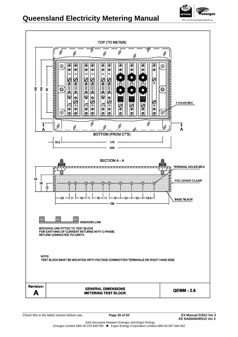
2.21.2.1 A test block supplied by the metering provider shall be incorporated in all installations with current transformer metering. (Refer to Drawing QEMM 2.6).
2.21.2.2 The test block shall be mounted immediately below, and in the same plane as the current transformer meter, such that the voltage connection terminals are on the right hand side when viewed from the front of the test block. (Refer to Drawings QEMM 2.4 and 2.5).
2.21.2.3 Connecting wiring shall be enclosed under the test block cover (surface wiring is not permitted).
Wiring to Current Transformers, Test Blocks etc. 2.21.3
2.21.3.1 The connections and colour coding shown in Drawing QECMM 2.4 shall be the standard. Where multi-core cables are used for special site requirements (e.g. armoured cables required) the cores must be individually identified Where single insulated grey coloured cable is not available one of the following arrangements may be used:
(a) single double insulated (SDI) cable no larger than 6mm² with grey coloured sheathing; or
(b) black single insulated conductors sleeved at both ends with not less than 300mm of grey coloured sleeving.
2.21.3.2 All voltage and current meter wiring (other than voltage circuit fuse supply conductors referred to in Clause 2.18.2.4) shall be PVC insulated stranded cable of no more than 7 strands. No joints are permitted in these conductors.
2.21.3.3 Where 2.5mm2 conductors are used the bare ends shall be doubled over prior to connection to the current transformers and test block to facilitate a secure connection to the terminals.
2.21.3.4 The insulation on all voltage and current meter wiring should be stripped back 15mm (30mm where doubled up 2.5mm2 is used) to ensure terminal screws make positive contact with the bare conductor. It is essential that terminal screws are connected securely to the bare conductors and not to the insulation of the wiring.
2.21.3.5 All current transformer wiring shall be enclosed in a continuous conduit, cable trunking or earthed metal duct from the current transformer chamber to the metering enclosure.
2.21.3.6 Current transformer metering secondary wiring shall be earthed as shown in Drawing QEMM 2.4. The earth conductor shall be connected directly to the main earth conductor or earth bar and not to a separate earthed medium such as the switchboard frame.
2.21.3.7 The earthing conductor shall be PVC insulated stranded cable of no more than 7 strands and can be 2.5mm2 cable for all current transformer metering installations.
2.21.3.8 A meter neutral label shall be attached to the meter neutral conductor adjacent to its connection to the main neutral. (Refer to QECM for metering neutral conductor connection details).

Queensland Electricity Metering Manual
Check this is the latest version before use. Page 17 of 63 EX Manual 01812 Ver 2 EE NA000403R510 Ver 2
Joint document between Energex and Ergon Energy Energex Limited ABN 40 078 849 055 Ergon Energy Corporation Limited ABN 50 087 646 062
2.21.3.9 Cable tails through meter panels should have a minimum length of 150mm to allow for connection into the meters. Current transformer meters will be erected and connected by the metering provider’s personnel only.
TABLE 2.5
Rated Burden
Max Circuit
Length 2.5 mm²
Max Route Length 2.5
mm²
Max Circuit Length 4mm²
Max Route Length 4
mm²
Max Circuit
Length 6 mm²
Max Route Length 6
mm²
5 VA 15m 7.5m 25m 12.5m 36m 18m
15 VA 45m 22.5m 80m 40m
Note: 200/5 ratio CTs are supplied with a rated burden of 5 VA 800/5 and 1500/5 ratio CTs are supplied with a rated burden of 15 VA.
2.21.3.10 All current transformer metering, wiring and installations are to be completed in accordance with the wiring diagrams in this manual.
2.21.3.11 To ensure compliance of the current transformer metering, contractors should use the Electrical Contractor’s LV CT Metering Check Sheet. This form can be changed to include the contractor’s logo and be part of the contractor’s quality system. Additional checks can be included if considered necessary.
Changes to Existing Current Transformer Metering Installations 2.21.4
When all or part of the existing metering installation requires changing (e.g. upgrading of a switchboard, change to the type of supply), the metering provider may require the total metering installation, including current transformers, to be upgraded to comply with the requirements of this manual and the National Electricity Rules.
Changes to Existing Current Transformer Metering Installations 2.21.5
Ergon Energy requires all LV current transformer metering installation designs to have prior approval for the metering arrangement. This requires the submission of Switchboard Layout and Single Line Diagrams as early as possible to allow design modifications to be carried out if necessary prior to switchboards being built. If this information is not provided Ergon Energy cannot guarantee supply will be connected if the switchboard does not comply. This requirement arises from the distances between sites in the Ergon Energy area of supply. Early submission of drawings will assist in reducing the time and costs for all parties and avoid late modifications of current transformer metering switchboards.

Queensland Electricity Metering Manual
Check this is the latest version before use. Page 18 of 63 EX Manual 01812 Ver 2 EE NA000403R510 Ver 2
Joint document between Energex and Ergon Energy Energex Limited ABN 40 078 849 055 Ergon Energy Corporation Limited ABN 50 087 646 062
Electrical Contractor’s LV CT Metering Check Sheet
Address Where CT Metering Installed: National Metering Identifier (NMI) (If known):
Details of Electrical Mechanic Responsible for Testing of CT Installation: Name: Licence No:
Pre-commissioning Checks
Clause No.
Checklist
Checked
Comments Switchboard/CT Chamber 2.6.2 Lockable isolator on line side of CTs: 2.17.1 Dedicated CT chamber provided: 2.17.2 CT chamber correctly labelled: 2.17.4 Removable CT chamber cover fitted with 2
handles:
Current Transformers 2.16 CT ratio matches expected load: 2.17.3 No exposed live parts within CT chamber: 2.18.1.1 Primary and secondary polarity is correct: 2.18.1.1 Removable bus bars allow CTs to be easily
replaced:
2.18.1.2 CT secondary terminals are accessible: Voltage Circuit Fuses 2.18.2.1 Fuses carriers are accessible and easily
removable:
2.18.2.3 Fuses are connected to the line side of the CTs:
2.18.2.4 Cables from bus bars to fuses are ≤ 500mm and a minimum. of 10mm2 SDI:
2.18.2.4 Correct marking of cables from bus bars to fuses (e.g. trace or bell out cables):
Meter Neutral & Earthing AS/NZS 3000
Test continuity to confirm that cabinets are earthed:
2.21.3.8 Meter neutral is connected to main neutral and meter neutral label is attached:
Meter Panel Wiring & Test Block QECM Meter panel located in suitable location QECM Meter panel size is minimum 600 x 600mm
(or 460 x 600mm for single tariff CT installation):
QECM Meters are mounted at correct height: 2.19.2 Meter panel is hinged: QECM Meters and wiring spaced from heavy current
carrying conductors:
2.21.2 Test block is mounted correctly: 2.21.3.1 Colour coding is correct: 2.21.3.2 Meter wiring is correct size for circuit length: 2.31.3.6 Secondary returns are starred and earthed: Sealing 2.5 CT chamber, voltage circuit fuses and meter
panel are sealable:
Queensland Electricity Metering Manual
Check this is the latest version before use. Page 19 of 63 EX Manual 01812 Ver 2 EE NA000403R510 Ver 2
Joint document between Energex and Ergon Energy Energex Limited ABN 40 078 849 055 Ergon Energy Corporation Limited ABN 50 087 646 062

Queensland Electricity Metering Manual
Check this is the latest version before use. Page 20 of 63 EX Manual 01812 Ver 2 EE NA000403R510 Ver 2
Joint document between Energex and Ergon Energy Energex Limited ABN 40 078 849 055 Ergon Energy Corporation Limited ABN 50 087 646 062

Queensland Electricity Metering Manual
Check this is the latest version before use. Page 21 of 63 EX Manual 01812 Ver 2 EE NA000403R510 Ver 2
Joint document between Energex and Ergon Energy Energex Limited ABN 40 078 849 055 Ergon Energy Corporation Limited ABN 50 087 646 062

Queensland Electricity Metering Manual
Check this is the latest version before use. Page 22 of 63 EX Manual 01812 Ver 2 EE NA000403R510 Ver 2
Joint document between Energex and Ergon Energy Energex Limited ABN 40 078 849 055 Ergon Energy Corporation Limited ABN 50 087 646 062

Queensland Electricity Metering Manual
Check this is the latest version before use. Page 23 of 63 EX Manual 01812 Ver 2 EE NA000403R510 Ver 2
Joint document between Energex and Ergon Energy Energex Limited ABN 40 078 849 055 Ergon Energy Corporation Limited ABN 50 087 646 062

Queensland Electricity Metering Manual
Check this is the latest version before use. Page 24 of 63 EX Manual 01812 Ver 2 EE NA000403R510 Ver 2
Joint document between Energex and Ergon Energy Energex Limited ABN 40 078 849 055 Ergon Energy Corporation Limited ABN 50 087 646 062
Queensland Electricity Metering Manual
Check this is the latest version before use. Page 25 of 63 EX Manual 01812 Ver 2 EE NA000403R510 Ver 2
Joint document between Energex and Ergon Energy Energex Limited ABN 40 078 849 055 Ergon Energy Corporation Limited ABN 50 087 646 062

Queensland Electricity Metering Manual
Check this is the latest version before use. Page 26 of 63 EX Manual 01812 Ver 2 EE NA000403R510 Ver 2
Joint document between Energex and Ergon Energy Energex Limited ABN 40 078 849 055 Ergon Energy Corporation Limited ABN 50 087 646 062

Queensland Electricity Metering Manual
Check this is the latest version before use. Page 27 of 63 EX Manual 01812 Ver 2 EE NA000403R510 Ver 2
Joint document between Energex and Ergon Energy Energex Limited ABN 40 078 849 055 Ergon Energy Corporation Limited ABN 50 087 646 062

Queensland Electricity Metering Manual
Check this is the latest version before use. Page 28 of 63 EX Manual 01812 Ver 2 EE NA000403R510 Ver 2
Joint document between Energex and Ergon Energy Energex Limited ABN 40 078 849 055 Ergon Energy Corporation Limited ABN 50 087 646 062
Queensland Electricity Metering Manual
Check this is the latest version before use. Page 29 of 63 EX Manual 01812 Ver 2 EE NA000403R510 Ver 2
Joint document between Energex and Ergon Energy Energex Limited ABN 40 078 849 055 Ergon Energy Corporation Limited ABN 50 087 646 062
Queensland Electricity Metering Manual
Check this is the latest version before use. Page 30 of 63 EX Manual 01812 Ver 2 EE NA000403R510 Ver 2
Joint document between Energex and Ergon Energy Energex Limited ABN 40 078 849 055 Ergon Energy Corporation Limited ABN 50 087 646 062

Queensland Electricity Metering Manual
Check this is the latest version before use. Page 31 of 63 EX Manual 01812 Ver 2 EE NA000403R510 Ver 2
Joint document between Energex and Ergon Energy Energex Limited ABN 40 078 849 055 Ergon Energy Corporation Limited ABN 50 087 646 062
Queensland Electricity Metering Manual
Check this is the latest version before use. Page 32 of 63 EX Manual 01812 Ver 2 EE NA000403R510 Ver 2
Joint document between Energex and Ergon Energy Energex Limited ABN 40 078 849 055 Ergon Energy Corporation Limited ABN 50 087 646 062

Queensland Electricity Metering Manual
Check this is the latest version before use. Page 33 of 63 EX Manual 01812 Ver 2 EE NA000403R510 Ver 2
Joint document between Energex and Ergon Energy Energex Limited ABN 40 078 849 055 Ergon Energy Corporation Limited ABN 50 087 646 062

Queensland Electricity Metering Manual
Check this is the latest version before use. Page 34 of 63 EX Manual 01812 Ver 2 EE NA000403R510 Ver 2
Joint document between Energex and Ergon Energy Energex Limited ABN 40 078 849 055 Ergon Energy Corporation Limited ABN 50 087 646 062

Queensland Electricity Metering Manual
Check this is the latest version before use. Page 35 of 63 EX Manual 01812 Ver 2 EE NA000403R510 Ver 2
Joint document between Energex and Ergon Energy Energex Limited ABN 40 078 849 055 Ergon Energy Corporation Limited ABN 50 087 646 062

Queensland Electricity Metering Manual
Check this is the latest version before use. Page 36 of 63 EX Manual 01812 Ver 2 EE NA000403R510 Ver 2
Joint document between Energex and Ergon Energy Energex Limited ABN 40 078 849 055 Ergon Energy Corporation Limited ABN 50 087 646 062

Queensland Electricity Metering Manual
Check this is the latest version before use. Page 37 of 63 EX Manual 01812 Ver 2 EE NA000403R510 Ver 2
Joint document between Energex and Ergon Energy Energex Limited ABN 40 078 849 055 Ergon Energy Corporation Limited ABN 50 087 646 062

Queensland Electricity Metering Manual
Check this is the latest version before use. Page 38 of 63 EX Manual 01812 Ver 2 EE NA000403R510 Ver 2
Joint document between Energex and Ergon Energy Energex Limited ABN 40 078 849 055 Ergon Energy Corporation Limited ABN 50 087 646 062

Queensland Electricity Metering Manual
Check this is the latest version before use. Page 39 of 63 EX Manual 01812 Ver 2 EE NA000403R510 Ver 2
Joint document between Energex and Ergon Energy Energex Limited ABN 40 078 849 055 Ergon Energy Corporation Limited ABN 50 087 646 062

Queensland Electricity Metering Manual
Check this is the latest version before use. Page 40 of 63 EX Manual 01812 Ver 2 EE NA000403R510 Ver 2
Joint document between Energex and Ergon Energy Energex Limited ABN 40 078 849 055 Ergon Energy Corporation Limited ABN 50 087 646 062
Queensland Electricity Metering Manual
Check this is the latest version before use. Page 41 of 63 EX Manual 01812 Ver 2 EE NA000403R510 Ver 2
Joint document between Energex and Ergon Energy Energex Limited ABN 40 078 849 055 Ergon Energy Corporation Limited ABN 50 087 646 062

Queensland Electricity Metering Manual
Check this is the latest version before use. Page 42 of 63 EX Manual 01812 Ver 2 EE NA000403R510 Ver 2
Joint document between Energex and Ergon Energy Energex Limited ABN 40 078 849 055 Ergon Energy Corporation Limited ABN 50 087 646 062

Queensland Electricity Metering Manual
Check this is the latest version before use. Page 43 of 63 EX Manual 01812 Ver 2 EE NA000403R510 Ver 2
Joint document between Energex and Ergon Energy Energex Limited ABN 40 078 849 055 Ergon Energy Corporation Limited ABN 50 087 646 062

Queensland Electricity Metering Manual
Check this is the latest version before use. Page 44 of 63 EX Manual 01812 Ver 2 EE NA000403R510 Ver 2
Joint document between Energex and Ergon Energy Energex Limited ABN 40 078 849 055 Ergon Energy Corporation Limited ABN 50 087 646 062
Queensland Electricity Metering Manual
Check this is the latest version before use. Page 45 of 63 EX Manual 01812 Ver 2 EE NA000403R510 Ver 2
Joint document between Energex and Ergon Energy Energex Limited ABN 40 078 849 055 Ergon Energy Corporation Limited ABN 50 087 646 062

Queensland Electricity Metering Manual
Check this is the latest version before use. Page 46 of 63 EX Manual 01812 Ver 2 EE NA000403R510 Ver 2
Joint document between Energex and Ergon Energy Energex Limited ABN 40 078 849 055 Ergon Energy Corporation Limited ABN 50 087 646 062

Queensland Electricity Metering Manual
Check this is the latest version before use. Page 47 of 63 EX Manual 01812 Ver 2 EE NA000403R510 Ver 2
Joint document between Energex and Ergon Energy Energex Limited ABN 40 078 849 055 Ergon Energy Corporation Limited ABN 50 087 646 062

Queensland Electricity Metering Manual
Check this is the latest version before use. Page 48 of 63 EX Manual 01812 Ver 2 EE NA000403R510 Ver 2
Joint document between Energex and Ergon Energy Energex Limited ABN 40 078 849 055 Ergon Energy Corporation Limited ABN 50 087 646 062

Queensland Electricity Metering Manual
Check this is the latest version before use. Page 49 of 63 EX Manual 01812 Ver 2 EE NA000403R510 Ver 2
Joint document between Energex and Ergon Energy Energex Limited ABN 40 078 849 055 Ergon Energy Corporation Limited ABN 50 087 646 062

Queensland Electricity Metering Manual
Check this is the latest version before use. Page 50 of 63 EX Manual 01812 Ver 2 EE NA000403R510 Ver 2
Joint document between Energex and Ergon Energy Energex Limited ABN 40 078 849 055 Ergon Energy Corporation Limited ABN 50 087 646 062
Queensland Electricity Metering Manual
Check this is the latest version before use. Page 51 of 63 EX Manual 01812 Ver 2 EE NA000403R510 Ver 2
Joint document between Energex and Ergon Energy Energex Limited ABN 40 078 849 055 Ergon Energy Corporation Limited ABN 50 087 646 062
Queensland Electricity Metering Manual
Check this is the latest version before use. Page 52 of 63 EX Manual 01812 Ver 2 EE NA000403R510 Ver 2
Joint document between Energex and Ergon Energy Energex Limited ABN 40 078 849 055 Ergon Energy Corporation Limited ABN 50 087 646 062

Queensland Electricity Metering Manual
Check this is the latest version before use. Page 53 of 63 EX Manual 01812 Ver 2 EE NA000403R510 Ver 2
Joint document between Energex and Ergon Energy Energex Limited ABN 40 078 849 055 Ergon Energy Corporation Limited ABN 50 087 646 062

Queensland Electricity Metering Manual
Check this is the latest version before use. Page 54 of 63 EX Manual 01812 Ver 2 EE NA000403R510 Ver 2
Joint document between Energex and Ergon Energy Energex Limited ABN 40 078 849 055 Ergon Energy Corporation Limited ABN 50 087 646 062

Queensland Electricity Metering Manual
Check this is the latest version before use. Page 55 of 63 EX Manual 01812 Ver 2 EE NA000403R510 Ver 2
Joint document between Energex and Ergon Energy Energex Limited ABN 40 078 849 055 Ergon Energy Corporation Limited ABN 50 087 646 062
Queensland Electricity Metering Manual
Check this is the latest version before use. Page 56 of 63 EX Manual 01812 Ver 2 EE NA000403R510 Ver 2
Joint document between Energex and Ergon Energy Energex Limited ABN 40 078 849 055 Ergon Energy Corporation Limited ABN 50 087 646 062
Queensland Electricity Metering Manual
Check this is the latest version before use. Page 57 of 63 EX Manual 01812 Ver 2 EE NA000403R510 Ver 2
Joint document between Energex and Ergon Energy Energex Limited ABN 40 078 849 055 Ergon Energy Corporation Limited ABN 50 087 646 062

Queensland Electricity Metering Manual
Check this is the latest version before use. Page 58 of 63 EX Manual 01812 Ver 2 EE NA000403R510 Ver 2
Joint document between Energex and Ergon Energy Energex Limited ABN 40 078 849 055 Ergon Energy Corporation Limited ABN 50 087 646 062
APPENDIX A - GLOSSARY OF TERMS Accredited Auditor A person appointed under section 129 of the Electrical Safety Act
2002 to audit high voltage or hazardous area installations before connection to supply. Further information may be obtained from the Electrical Safety Office.
AEMO ‘Australian Energy Market Operator’ is responsible for the day to day management of wholesale and retail energy market operations and emergency management protocols; on-going market development required to incorporate new rules, infrastructure and participants; and long term market planning through demand forecasting data and scenario analysis.
AF Receiver See “Network Device” Capital Contribution A contribution towards costs associated with a standard control
service, such as any necessary augmentation of connection assets at the connection point, dedicated network extension or augmentation of the shared distribution network to accommodate the connection/modification. A capital contribution will only be levied where there is a difference between the cost to provide the connection service and the revenue that will be earned by the distributor from the connection service.
Card Operated Meter A meter that contains control equipment that switches on and off in accordance with the amount of credit stored in the meter.
Common Property Common property means so much of a parcel as from time to time is not comprised in any lot. Building Units and Group Titles Act 1980
Connection Point, Point of Supply
The agreed point of supply established between Network Service Provider(s) and another Registered Participant, Non-Registered Customer or franchise customer.
Connection Policy
The distributor’s connection policy provides an outline of connection services, when connection charges may be payable by customers and how those charges are calculated.
Consumer’s Mains The conductors between the connection point and the main switchboard.
Consumer’s Terminals Note (1): AS/NZS 3000 refers to the ‘Connection Point’ as the ‘Point
of Supply’. Previous editions of AS/NZS 3000 referred to the ‘Connection Point’ as the ‘consumer’s terminals’.
Note (2): The Queensland Electricity Regulation 2006 uses the definition ‘consumer’s terminals’.
Note (3): The National Electricity Rules uses the definition ‘connection point’.
Note (4): This is the point which differentiates the responsibilities of the Network Service Provider and the application of AS/NZS 3000.

Queensland Electricity Metering Manual
Check this is the latest version before use. Page 59 of 63 EX Manual 01812 Ver 2 EE NA000403R510 Ver 2
Joint document between Energex and Ergon Energy Energex Limited ABN 40 078 849 055 Ergon Energy Corporation Limited ABN 50 087 646 062
Controlled Load, Controlled Supply
Those loads that are wired separately from other appliances, are controlled by means of frequency injection receiver or time clock, and are separately metered from the remaining load at the metering point.
Current Transformer Metering
A metering arrangement where electricity flow is measured by a meter using current transformers (CTs).
Customer A person, including a relevant body corporate, who receives, or wants to receive, a supply of electricity for a premises from an electricity entity or special approval holder.
Direct Connected Meter A meter where the electricity flow is directly measured by the meter i.e. the current under measurement passes through the meter itself.
Distribution Entity, Distributor
A distribution entity is a person who holds a distribution authority that authorises its holder to supply electricity using a supply network within its distribution area. See sections 37, 38 and 39 of the Queensland Electricity Act 1994. (Refer to definition for Relevant Distribution Entity).
Electrical Contractor (EC)
A person licensed under the Electrical Safety Act 2002 to conduct a business or undertaking that includes the performance of electrical work.
Electrical Work Request (EWR)
The request from the customer’s electrical contractor to a distributor to perform a distribution service e.g. (i) Energex - Form 2; or (ii) Ergon Energy - Form A - Request for Initial Connection, Metering
Change or Service Alteration
Energex Energex Limited - ABN 40 078 849 055
Enhanced Metering A scheme, which is not normally considered to be part of standard metering as described in this manual (e.g. has pulse inputs, outputs, or remote communications). Additions that are above and beyond the metering provided in this manual.
Ergon Energy Ergon Energy Corporation Limited ABN 50 087 646 062
EVSE Electric Vehicle Supply Equipment as defined in AS/IEC 62196
Excluded Customer A customer who cannot choose their retailer. For example, customers connected to isolated power systems.
Gross Energy Scheme The Gross Energy Scheme separately meters the full energy output of the MEGU. The energy consumed at the premises is metered normally.
High Voltage Metering A high voltage metering arrangement where electricity flow is
measured by a meter using current transformers and voltage transformers.

Queensland Electricity Metering Manual
Check this is the latest version before use. Page 60 of 63 EX Manual 01812 Ver 2 EE NA000403R510 Ver 2
Joint document between Energex and Ergon Energy Energex Limited ABN 40 078 849 055 Ergon Energy Corporation Limited ABN 50 087 646 062
Isolated Power System A supply network that does not form part of and is not connected to
the national grid and may include an isolated feeder.
Large Customer A customer whose annual consumption is equal to, or greater than, 100MWh, and is connected to the distributor’s network.
Large Non-market Customer
A large non-market customer, for premises, is a large customer for the premises who is also a non-market customer for the premises.
MEGU A grid connected Micro Embedded Generating Unit (also referred to as Inverter Energy System or IES) as defined in AS 4777.
Metering Coordinator A person who has been registered by AEMO under Chapter 2 of the National Electricity Rules to engage in the coordination and provision of metering services at a connection point in accordance with Chapter 7 of the National Electricity Rules.
Metering Data Agent An agent appointed by AEMO to undertake the collection, processing and transfer of metering data to AEMO and other registered participants.
Metering Data Provider
A person who meets the requirements listed in schedule 7.3 of the National Electricity Rules and has been accredited and registered by AEMO to undertake the collection, processing, storage and delivery of metering data and the management of NMI Standing Data.
Metering Provider (MP) A person who meets the requirements listed in schedule 7.2 of the National Electricity Rules and has been accredited and registered by AEMO to undertake the provision, installation and maintenance of metering installations. Note: The distributor is the metering provider in non-NEM areas.
Micro Embedded Generating Unit
A generator that is compliant with AS4777, that is, an inverter system to be connected to the low voltage distribution network.
NATA The National Association of Testing Authorities.
National Electricity Rules
The rules under which the National Electricity Market operates.
National Metering Identifier (NMI)
A National Metering Identifier (NMI) is a unique national identifier that relates to the metering installation at a customer’s premises.
Net Energy Scheme The Net Energy Scheme provides for the separate measurement of the energy supplied from the LV network to the customer’s installation in excess of the MEGU generation, and the excess energy supplied to the LV network from the premises by the MEGU after the energy needs at the premises are met.

Queensland Electricity Metering Manual
Check this is the latest version before use. Page 61 of 63 EX Manual 01812 Ver 2 EE NA000403R510 Ver 2
Joint document between Energex and Ergon Energy Energex Limited ABN 40 078 849 055 Ergon Energy Corporation Limited ABN 50 087 646 062
Network Device, AF Receiver
Apparatus or equipment that: (a) enables a distributor to monitor, operate or control the network for the purposes of providing network services, which may include switching devices, measurement equipment and control equipment; and (b) is located at or adjacent to a metering installation at the connection point of a customer.
NMI Classification Small - annual consumption less than 100MWh Large - annual consumption equal to, or greater than 100MWh.
Point of Attachment
The point at which aerial conductors of a service line or aerial consumer’s mains are terminated on a customer’s structure.
Point of Entry The point at which the consumer’s mains or the underground service cable enters a structure.
Premises Premises includes - (a) a building or other structure; and (b) a part of a building or other structure; and (c) land where a building or other structure is situated. Premises, of a customer, means premises owned or occupied by the customer. Queensland Electricity Act 1994
QECM Queensland Electricity Connection Manual
QECMM Queensland Electricity Connection and Metering Manual. On 24th August 2018 the QECMM content was separated into two new documents, the QECM and the QEMM and the QECMM was withdrawn.
QEMM Queensland Electricity Metering Manual
Relevant Distribution Entity, Distributor
The relevant distribution entity for a premises, means the distribution entity to whose supply network the premises are, or will be, connected. Note: For the purposes of this document the relevant distribution
entity will be referred to as the ‘distributor’.
Relevant Retail Entity, Retailer
The relevant retail entity for a premise, means the retail entity who, under a retail contract, supplies or has agreed to supply electricity to the premises. Note: For the purposes of this document the relevant retail entity will
be referred to as the ‘retailer’.
Retail Entity A person who holds a retail authority to sell electricity and retail services (a ‘retail authority’ authorises its holder to provide customer retail services under the terms of the authority).
RPEQ Registered Professional Engineer Queensland.

Queensland Electricity Metering Manual
Check this is the latest version before use. Page 62 of 63 EX Manual 01812 Ver 2 EE NA000403R510 Ver 2
Joint document between Energex and Ergon Energy Energex Limited ABN 40 078 849 055 Ergon Energy Corporation Limited ABN 50 087 646 062
Rural/Isolated Area A rural/Isolated area is defined as one with a density of less than 5 lots per hectare (i.e. would generally have a dedicated supply transformer). Note: This definition is only applicable within the Ergon Energy
distribution area.
Service Line
An electric line that- (a) forms part of the works of an electricity entity; and (b) connects consumer terminals to - (i) other parts of the works of the electricity entity; or (ii) the works of another electricity entity. Schedule 9 of the Queensland Electricity Regulation 2006.
Small Customer A customer who consumes less than 100MWh per annum and is connected to the distributor’s network.
SOR
Service Order Request - This is a request from a Retailer to a Distributor to perform a distribution service (e.g. New Connections, Metering Alterations and Service Upgrades). It is also referred to as a B2B request.
Suitable Mains Connection Box
A mains connection box that is deemed to be compliant with the distributor’s technical specifications. Details are available by contacting the distributor via the methods listed on page 1
Two element Meter
A single phase two element device which includes both metering and load switching within one meter.
Type 1-7 Metering Installation
As defined in the National Electricity Rules
Unmetered Supply A Type 7 metering installation classification (NER) where a metering installation does not require a meter to measure the flow of electricity in a power conductor and accordingly there is a requirement to determine by other means the energy data that is deemed to flow in the power conductor and managed by the relevant Distribution Entity.
Urban A residential area with a system of street lighting.
Queensland Electricity Metering Manual
Check this is the latest version before use. Page 63 of 63 EX Manual 01812 Ver 2 EE NA000403R510 Ver 2
Joint document between Energex and Ergon Energy Energex Limited ABN 40 078 849 055 Ergon Energy Corporation Limited ABN 50 087 646 062
APPENDIX B – AMENDMENT RECORD
Please Note: It is not possible to cover all of the changes in the following list, nor can the changes be covered in the deail and context as they appear within the manual. As an Electrical Contractor it is the responsibility of you and your endorees to be fully conversant with the content and requirements of the Queensland Electricty Metering Manual.
Date 24/08/18 Previous Version: Version 12 of the QECMM
Version 1 includes the serpartaion of ther metering component from the connection component to create the QEMM
Additionally, cluases have been rearranged to group similar items together.